Prepared by: Gajanan Desurkar STRENGTH OF MATERIALS …
28
STRENGTH OF MATERIALS [15ME31T] Question Bank – Unit Wise Department of Mechanical Engineering , Jain Polytechnic, Belagavi Page 1 Unit – 1 SIMPLE STRESSES AND STRAINS S No Questions Marks Appeared in 1 Define Young’s modulus & shear modulus. 5 Nov 2016 2 Explain Hoop stress and longitudinal stress in cylindrical shell. 5 Nov 2016,May 2018, APRIL 2019, Nov 2019 3 Explain Bulk modulus and modulus of rigidity. 5 May 2017 4 Define Poisson’s ratio and modulus of rigidity. 5 May 2017,Nov 2018, April 2019, Nov 2019 5 Explain thermal stress and volumetric strain. 5 Nov 2017 6 Define Poisson’s ratio and modulus of Elasticity. 5 May 2018 7 Explain linear and lateral strain 5 Nov 2018 8 A tensile test is performed on a brass specimen 10mm in diameter using a gauge length of 50mm when applying axial tensile load of 25Kn it is observed that the distance between the gauge mark increased by 0.152mm. calculate modulus of elasticity of brass 10 Nov 2018 9 The Young’s modulus for a given material is 100Kn/mm^2 and its modulus of rigidity is 40Kn/mm^2. Determine its bulk modulus and also its lateral contraction if the diameter is 50mm and length is 2m and extension is 2mm 10 Nov 2018 10 A circular rod of steel is 20mm in diameter and 500mm long it is subjected to an axial pull of 45kN.If E for steel is 2*10^5 N/mm^2 find stress, linear strain, change in length, change in volume take u=0.25. 10 Nov 2016 11 A cylindrical shell of 1.3m diameter is made up of 18mm thick plates. Find the circumference & longitudinal stress in the plates. If the boiler is subjected to an internal pressure of 2.4Mpa.Take efficiency of joints as 70%. 10 Nov 2016 Prepared by: Gajanan Desurkar
Transcript of Prepared by: Gajanan Desurkar STRENGTH OF MATERIALS …

STRENGTH OF MATERIALS [15ME31T]
Question Bank – Unit Wise Department of Mechanical Engineering , Jain Polytechnic, Belagavi Page 1
Unit – 1 SIMPLE STRESSES AND STRAINS
S
No
Questions Marks Appeared in
1 Define Young’s modulus & shear modulus. 5 Nov 2016
2 Explain Hoop stress and longitudinal stress in cylindrical
shell. 5
Nov 2016,May 2018,
APRIL 2019, Nov 2019
3 Explain Bulk modulus and modulus of rigidity. 5 May 2017
4 Define Poisson’s ratio and modulus of rigidity.
5 May 2017,Nov 2018,
April 2019, Nov 2019
5 Explain thermal stress and volumetric strain. 5 Nov 2017
6 Define Poisson’s ratio and modulus of Elasticity. 5 May 2018
7 Explain linear and lateral strain 5 Nov 2018
8
A tensile test is performed on a brass specimen 10mm in
diameter using a gauge length of 50mm when applying axial
tensile load of 25Kn it is observed that the distance between
the gauge mark increased by 0.152mm. calculate modulus of
elasticity of brass
10
Nov 2018
9
The Young’s modulus for a given material is 100Kn/mm^2
and its modulus of rigidity is 40Kn/mm^2. Determine its bulk
modulus and also its lateral contraction if the diameter is
50mm and length is 2m and extension is 2mm
10
Nov 2018
10
A circular rod of steel is 20mm in diameter and 500mm long
it is subjected to an axial pull of 45kN.If E for steel is 2*10^5
N/mm^2 find stress, linear strain, change in length, change in
volume take u=0.25.
10 Nov 2016
11
A cylindrical shell of 1.3m diameter is made up of 18mm
thick plates. Find the circumference & longitudinal stress in
the plates. If the boiler is subjected to an internal pressure of
2.4Mpa.Take efficiency of joints as 70%.
10 Nov 2016
Prepared by: Gajanan Desurkar

STRENGTH OF MATERIALS [15ME31T]
Question Bank – Unit Wise Department of Mechanical Engineering , Jain Polytechnic, Belagavi Page 2
12
A hollow steel tube 3.5m long has external diameter 120mm
and is subjected to a tensile load of 400KN and extension
measured is 2mm Determine the internal diameter E=200
GPa.
10 May 2017
13
A circular rod of steel is 20mm in diameter and 500mm long
it is subjected to an axial pull of 45KN.If
E=200*10^3N/mm^2.Find stress,linear strain ,change in
length and change in volume of the bar.
10 May 2017
14
A steel bar 50mm wide,12mm thick,300mm long is
subjected to an axial pull of 100KN.Find change in
length,width,thickness and volume of the bar.
E=2*10^5N/mm^2,u=0.32
10 Nov 2017
15
A Bar of 30mm diameter is subjected to a pull of 60KN.Yhe
measured extension on gauge length of 200mm is 0.09mm
and the change in diameter is 0.0039mm.Calculate the
poisson’s ratio & thr values of the Young’s modulus, Rigidity
modulus & Bulk Modulus.
10 Nov 2017
16
A bar of 30mm dia.is subjected to a pull of 60KN.The
measured extension is 0.09mm and gauge length of 200mm
and change in diameter is 0.0039mm.calculate a)Poisson’s
ratio b)Young’s modulus c)Bulk Modulus d)Rigidity Modulus
10 May 2018
17
A steel bar 2m long 40mm wide and 20mm thickness is
subjected to axial pull of 160kN in the direction of its length.
Find the change in length, width and thickness of bar. Take
E=200GPa and Poisson’s ratio=0.3
10 May 2018
18 Explain thermal stresses and bulk modulus 5 APRIL/ MAY 2019
19 Define shear force and point of contraflexure in beams 5 APRIL 2019
20 A bar of steel 4m long ,30mm wide and 20mm thickness is
subjected to an axial load of 30Kn in the direction of its 6 April 2019

STRENGTH OF MATERIALS [15ME31T]
Question Bank – Unit Wise Department of Mechanical Engineering , Jain Polytechnic, Belagavi Page 3
length ,find the change in length ,thickness and volume if
Youngs modulus is 200Kn/mm^2
21
A mild steel bar of 15mm diameter was subjected to tensile
test .the test bar was found to yield at a load of 90kn and it
attains maximum lad of 180kn and and ultimately fails at a
load of 67.5kn.determine the following. Tensile stress at the
yield point, ultimate stress and stress at breaking point, if the
diameter of the neck is 7.5mm
10 April 2019
22
A rod of diameter 15 mm and 50 mm long is subjected to
tensile load of 25 kN. The modules of elasticity for steel rod
may be taken as 200 kN/mm2. Find the stress, strain and
elongation of the bar due to applied load.
10 Nov 2019
23
A bar of 30 mm diameter is subjected to an axial pull of 80
kN. The measured extension is 0.1 mm on a gauge length of
200 mm and the change in diameter is 0.04 m. Calculate the
Poisson's ratio and the values of Young's modulus, bulk
modulus and modulus of rigidity
10 Nov 2019
UNIT – 2 MOMENT OF INERTIA
1 Define C.G. and Moment of Inertia. 5 Nov 2016
2 Locate the C.G. of Triangle, Rectangle, Circle, and Semicircle
& Trapezium with the help of plain figure. 5
Dec 2016/May 2017/May
2018/Nov 2018 APRIL
2019, Nov 2019
3 Find the moment of Inertia of Rectangular section about its
base. 5 May 2017
4
State parallel & perpendicular axis theorem applied to
moment of Inertia. 5
Dec 2017/May 2018/Nov
2018 APRIL 2019, Nov
2019
5 a)Determine the centroid of the T-section 150*120*20mm 5+5=
10 Dec 2016

STRENGTH OF MATERIALS [15ME31T]
Question Bank – Unit Wise Department of Mechanical Engineering , Jain Polytechnic, Belagavi Page 4
b)Calculate the C.G. of the lamina (All the dimensions are in
mm)
6
Find the centroid of I section
Top flange 100*20mm
Web 20mm*100mm
Bottom flange 200*20mm
05,10
Nov 2018 ,April 2019
7
Calculate the center of gravity of the section shown in figure
05
Nov 2018
8
a)Find Moment of Inertia.
10 Dec 2016/May 2018

STRENGTH OF MATERIALS [15ME31T]
Question Bank – Unit Wise Department of Mechanical Engineering , Jain Polytechnic, Belagavi Page 5
9
Find the moment of inertia of a T section shown in fig.about
X-X axis and Y-Y passing through the center of gravity of the
section
10
Nov 2018
10
a)Calculate the Centroid of L-section.
5+5=1
0
May 2017/May 2018
April 2019, Nov 2019
11
b)Calculate the centroid .
10 April 2019
12 Find the M.I. of I-Section about XX & YY axis. 10 Dec 2016

STRENGTH OF MATERIALS [15ME31T]
Question Bank – Unit Wise Department of Mechanical Engineering , Jain Polytechnic, Belagavi Page 6
13
Find the Centroid of the lamina
10 May 2017
14
Find the moment of Inertia about the Centroidal axis XX &
YY
10 May 2017/May 2018
15
Find the moment of inertia [Ixx] of I section having top flange
of 100 mm x 20 mm, web 120 x 20 mm and bottom flange
150 x 20 mm.
10 Nov 2019
UNIT-3 SFD & BMD
1 Define shear force and bending moment in beams. 5 Nov 2016, Nov 2019
STRENGTH OF MATERIALS [15ME31T]
Question Bank – Unit Wise Department of Mechanical Engineering , Jain Polytechnic, Belagavi Page 7
2 Explain Sagging and Hogging bending moment.
5 May 2017/Nov 2018
APRIL 2019, Nov 2019
3 Name the type of loads acting on the beam with illustration. 5 May 2017/May 2018
4 Explain point of Contra-flexure in a beam.
5 Nov 2017/May
2018/Nov 2018
5 Name three types of beams & three types of loads with
sketches 5 Nov 2017
6
A cantilever 5m long carries point loads of 30KN & 10KN at
a distance of 1m & 5m from the fixed end. In addition to this
the beam carries a UDL 10KN/m between the point loads.
Draw SFD & BMD
10 Nov 2016/Nov 2018
7
A simply supported beam 4m long is subjected to two point
loads of 2KN & 4KN each at a distance of 1.5m & 3m from
the left end.Draw SFD & BMD.
10 Nov 2016
8
A simply supported beam of 8m carries an UDL of 5kN/m for
a length of 3m from the left support and point loads of 6Kn,
5kN and 4kN at 4m,5m and 6m from the left support. Draw
SFD and BMD.
10
Nov 2018
9 a)A cantilever beam of span 4m carries point loads of 2KN at
its free end & 5KN at 1m from free end. Sketch SFD & BMD. 5+5=10 May 2017
10
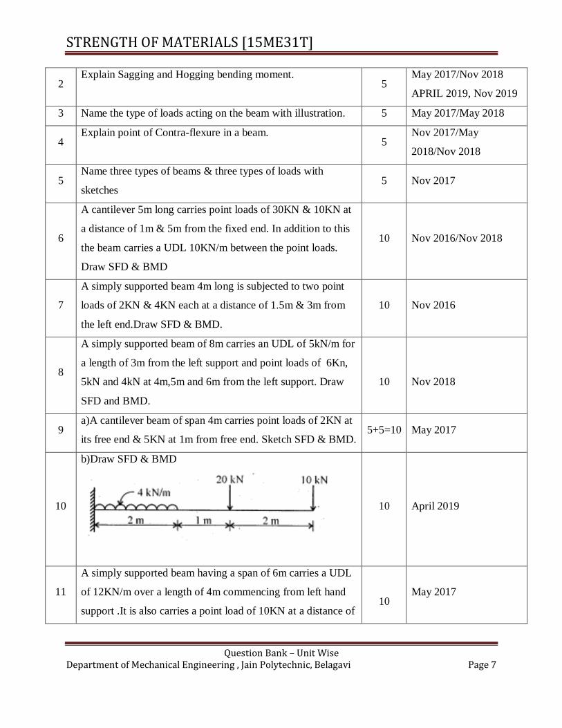
b)Draw SFD & BMD
10 April 2019
11
A simply supported beam having a span of 6m carries a UDL
of 12KN/m over a length of 4m commencing from left hand
support .It is also carries a point load of 10KN at a distance of
10 May 2017

STRENGTH OF MATERIALS [15ME31T]
Question Bank – Unit Wise Department of Mechanical Engineering , Jain Polytechnic, Belagavi Page 8
1m from the right support. Draw SFD & BMD.
12
A cantilever beam of span 3m carries an UDL of 2 KN/n
over a length of 2m from support. In addition it is also
carries point loads of 1KN,2KN,3KN at free end ,1m & 2m
from free end respectively .Draw SFD &BMD
10 Nov 2017
13
A simply supported beam of 8m span carries point loads of
10KN & 20KN at 3m & 5m respectively from the left
support. In addition it also carries a UDL of 10KN for 3 m
starting from the right support. Draw SFD & BMD
10 Nov 2017
14
Draw SFD and BMD for the cantilever beam shown in fig.
10 May 2018
15
Draw SFD and BMD for the simply supported beam shown in
fig.
10 May 2018
16
A cantilever 5m long carries point load of 30Kn and 10Kn at
a distance of 5m from fixed end.in addition to this the beam
carries a UDL of of 10Kn/m between the point load.
Construct shear force and bending moment diagram giving all
salient values
10
Nov 2018
17
A cantilever beam of length 4m subjected to a point load 3kn,
5kn, 8kn and 10kn at a distance of 1m,1.5m,3m and 3.5m
from the free end. draw SFD and BMD.
10 April 2019

STRENGTH OF MATERIALS [15ME31T]
Question Bank – Unit Wise Department of Mechanical Engineering , Jain Polytechnic, Belagavi Page 9
18
A simply supported beam 6m long is carrying a uniformaly
distributed load of 2kn/m over a length of 3m from the right
support.draw SFD and BMD for beam. Also calculate
maximum bending moment of the beam
10 April 2019
19
A cantilever beam of length 3 m subjected to point load of 5
KN, 8 KN and 12 KN at a distance of 1 m, 1.5 m and 2.5 m
from the free end. Draw SFD and BMD
10 Nov 2019
20
A simply supported beam of length 8 m carries two point
loads of 30 kN and 40 kN respectively at a distance of 1.5 m
and 6.5 m from the left support. Also it carries a UDL of 10
kN/m between the points loads. Draw shear force and bending
moment diagram.
10 Nov 2019
Unit - 4 THEORY OF SIMPLE BENDING
1
List the assumptions in Theory of simple bending.
5
Nov 2016/May
2017/May 2018/ Nov
2018, Nov 2019
2
Explain modulus of section for solid, rectangular and circular
sections. 5
Nov 2016/May
2017/May 2018/Nov
2018, Nov 2019
3 Write the bending equations with all notations. 5 May 2017, April 2019
4 Explain moment of resistance & modulus of rapture. 5 Nov 2017
5
The moment of inertia of the beam section 500mm deep is
69.49*10^7mm^4 find the longest span over which a beam of
this section when simply supported could carry a UDL of
50Kn/m run .the stress in the material is not to exceed
110N/mm^2.
10
Nov 2018
6
A steel plate is bent into a circular arc of 12 m radius. If the
plate section is 100mm wide & 20mm thick find the
maximum stress induced in the plate & also the bending
10 Nov 2016
STRENGTH OF MATERIALS [15ME31T]
Question Bank – Unit Wise Department of Mechanical Engineering , Jain Polytechnic, Belagavi Page 10
moment which can produce this stress. E=2*10^5 N/mm^2
7
A circular pipe of external diameter 70mm and thickness
10mm is used as a simply supported beam over effective span
of 2.5m. find the maximum point load that can be applied at
the center of span if permissible stress in the tube is
150N/mm^2.
10
Nov 2018
8
A timber beam of rectangular section supports a load of 20KN
UDL over a span of 3.6m.If depth of the beam is twice the
width & maximum stress is not to exceed 7MPa.find the
dimensions of the beam section.
10 Nov 2016/May 2017
9
A beam is simply supported and carries a UDL of 40KN/m
run over the whole span. If section of the beam is rectangular
having depth as 500mm.If the maximum stress in the material
of the beam is 120N/mm^2 & MI is 7*10^8 mm^4.Find the
span of the beam.
10 Nov 2017
10
A rectangular beam 40mm deep is simply supported over a
span of 5m long.what uniformly distributed load the beam
may carry if the bending stress is not to exceed 120MPa?Take
I =9*10^6 mm^4
10 May 2018
11
A circular pipe of external diameter 80mm and thickness
10mm is used as a simply supported beam over an effective
span of 3m.Find the maximum point load that can be applied
at the Centre of the span, if permissible stress of the tube is
150N/mm^2.
10 May 2018
12 Explain moment of resistance & radius of curvature in a beam 5 April 2019
13
A rectangular beam 300mm deep is simply supported over a
span of 4m long. what uniformly distributed load the beam
may carry if the bending stress is not to exceed 120MPa?Take
I =80*10^6 mm^4
10 April 2019
STRENGTH OF MATERIALS [15ME31T]
Question Bank – Unit Wise Department of Mechanical Engineering , Jain Polytechnic, Belagavi Page 11
14
A cast iron pipe of external diameter 60mm and 10mm
thickness and 5m long is supported at its end .the pipe carries
a point load of 100N at its center. calculate maximum bending
stress induced in the pipe
10 April 2019
15
A steel plate is bent into an arc of a circle of radius 10 m. If
the breadth of the plate is150 mm and thickness 25 mm and E
= 2 x 10⁵ N/mm
2. Calculate the maximum stress induced in
the plate and the bending moment which can produce this
stress
10 Nov 2019
16
A simply supported wooden beam of span 1.3 m is carrying a central
point load of 40 kN. If the allowable bending stress in the timber is
taken as 8 N/mm2 . Find the breadth and depth of the timber. Take b
= 0.6 d.
10 Nov 2019
UNIT –6 STRAIN ENERGY & IMPACT LOADING
1 Explain Proof resilience & modulus of resilience.
5 Nov 2016/May 2018,
Nov 2019
2 Explain strain Energy & resilience 5 Nov 2017/Nov 2018
3
An axial pull of 20KN is suddenly applied to steel rod 2.5m
long & 1000mm^2 in cross section. calculate the strain energy
which can be stored if E=2*10^5 N/mm^2
5 Dec 2016
4
a)An axial pull of 25KN is suddenly applied to steel rod 2m
long & 1000mm^2 in cross section. calculate the strain energy
which can be stored if E=2*10^5 N/mm^2
5 May 2017
5
b)An axial pull of 50KN is suddenly applied to a rod of 2m
long 40mm diameter .calculate the stress produced & strain
energy that can be stored if E=200KN/mm^2.
5 April 2019
6 Calculate the strain energy stored in a bar 2.5m long 50mm
wide &40mm thick when it is subjected to a tensile load of 50 5 Dec 2017, Nov 2019

STRENGTH OF MATERIALS [15ME31T]
Question Bank – Unit Wise Department of Mechanical Engineering , Jain Polytechnic, Belagavi Page 12
KN E=2*10^5 N/mm^2
7
Calculate the strain energy stored in a steel bar 2m long and
500mm^2 cross sectional area when it is subjected to a tensile
stress of 50 Kn/mm^2 E=2*10^5 N/mm^2.
5
NOV 2018
8
Calculate the strain energy stored in a bar 250mm long 40mm
wide &20mm thick when it is subjected to a tensile load of 50
KN E=2*10^5 N/mm^2.
5 May 2018
9 Define:(i)Resilience (ii)Proof Resilience (iii)modulus of
resilience 3 April 2019
10
An axial pull of 20KN is suddenly applied to steel rod 2.5m
long & 1000mm^2 in cross section. calculate the strain energy
which can be stored if E=200GPa
7 April 2019
UNIT – 6 THEORY OF TORSION
1 List the assumptions made in Theory of torsion. 5 May 2017/Nov 2018
April 2019, Nov 2019
2 Write the torsion equation with all notations. 5 May 2017/May 2018
3 Compare the strength of hollow & solid shaft. 5 Nov 2017 April 2019
4
A solid circular shaft is required to transmit 100KW at
180r.p.m. The permissible shear stress in the shaft is
60N/mm^2.Find the suitable diameter of the shaft. The angle
of twist is not to exceed 1degree in a length of 3m.The value
of rigidity modulus is 0.8*10^5 N/mm^2.
10 Nov 2016
5
A steel shaft transmits 105kw at 160rpm.If the shaft is
100mm in diameter and the torque on the shaft & the
maximum shear stress induced. Also find twist of the shaft in
a length of 6m. C=80*10^3 N/mm^2
10 May 2017
6
A solid circular shaft is required to transmit 120KW at
180r.p.m. The permissible shear stress in the shaft is
70N/mm^2.The maximum torque transmitted exceeds the
10 Dec 2017

STRENGTH OF MATERIALS [15ME31T]
Question Bank – Unit Wise Department of Mechanical Engineering , Jain Polytechnic, Belagavi Page 13
mean torque by 30%more than the mean torque. Find the
suitable diameter of the shaft. Also find the angle of twist in a
length of 2m.G=0.9*10^5 N/mm^2.
7
A solid shaft of 120mm diameter is required to transmit
200kW at 100rpm .If the angle of twist is not to exceed 2
degrees find the length of the shaft. Take Modulus of
rigidity=90GPa.
10 May 2018
8
A hollow shaft is required to transmit 300KN at 90rpm the
permissible shear stress in the shaft is 60Kn/mm^2. The
maximum torque transmitted exceeds the mean torque by
25% more than the mean torque .the internal diameter is half
of the external diameter. Find the internal diameter and
external diameter of the shaft
10
Nov 2018
9
A solid circular shaft is required to transmit 1MW at
240rpm.the permissible shear stress in the shaft is
60N/mm^2.the angle of twist is not to exceed 1 degree in a
length of 2.5m.the value of rigidity modulus is
80Kn/mm^2.find the diameter of shaft
7 April 2019
10
A solid circular shaft is required to transmit 100 kW at 180 rpm. The
permissible shear stress in the shaft is 60 N/mm2. Find the suitable
diameter of the shaft. The angle of twist is not to exceed 1° in a
length of 3 m. The value of rigidity modulus is 0.8 x 10⁵ N/mm
2.
10 Nov 2019

Mechanics of Machine [15ME32T ]
Question Bank – Unit Wise
Department of Mechanical Engineering, Jain Polytechnic Belagavi
Unit – 1- Simple Mechanism
1 Define Kinematic link. Briefly explain its types 5m
Nov
2017
Apr
2018
2 Explain self-closed pair & force- closed pair / differentiate between self-closed
pair and force closed pair 5m/4
m
Nov
2017
Apr
2017
Apr
2018
3. Explain single slider crank chain with sketch &mention its inversions 10m Nov - 1017
4.
Explain elliptical trammel with neat sketch
5m
Apr - 2017/ Nov - 2017
5. Explain Oldham’s coupling with neat sketch 5m
Apr - 2017/ Nov - 2017
6. Explain with neat sketch crank and slotted lever return motion mechanism
10m
/ 8m
Apr – 2017 / May 19
7. List types of constraint motion. Explain any one 5m Nov - 2016
8 Explain with a neat sketch beam engine 5m/5
Nov -16/Nov-18/Nov-
19
9. Explain with a neat sketch four bar chain 6m
Nov-
Dec
2018
10
.
Differentiate Higher and Lower pair 4m Nov – 2016
11 Explain with neat sketch Scotch yoke mechanism
5
Apr-2018 / Nov 2018
12 Explain with neat sketch completely constrained motion
6
Apr – 2018
13
Explain coupling rod of locomotive with neat sketch
7 Apr-18 / may 19
14 Define Inversion of mechanism
3
Apr – 2018
Mr.Sujit Sali

Mechanics of Machine [15ME32T ]
Question Bank – Unit Wise
Department of Mechanical Engineering, Jain Polytechnic Belagavi
15 Differentiate between machine and structure
5
Nov/Dec 2018
16
Define inversion of mechanism and list inversion of single slider crank chain / Explain inversion of mechanism
5 / 2 Nov/Dec
2018 May 19
17 Explain pendulum pump with neat sketch 5 Nov/Dec
2018
18 List the types of links. Explain any two 5 May 19
19 Explain mechanism 2 May 19
20 Explain with neat sketch Oldham’s coupling 8 May 19
21 Explain the following types of kinematic pairs. Give one example each. i. Sliding pair ii. Turning pair
5 Nov-19
22
22 Define kinematic chain. Name the different types of kinematic chains 5 Nov-19
23 Explain with neat sketches the three types of constrained motions 5 Nov-19
24 With neat sketch, explain a double slider crank chain, which is used to draw ellipses. 5 Nov-19
Unit – 2- Transmission of Power
1 List advantages and disadvantages of belt drive over rope drive. 5m Nov
2017
2 Explain with neat diagram stepped or cone pulley drive. 5m/5
m
Nov-17
/Nov-19
3
Two parallel shafts that are 3.5m apart are connected by two pulleys of 1m & 400mm diameters. The larger pulley being the driver runs at 220rpm. The belt weights 1.2 kg/m. The maximum tension in the belt is not to exceed 1.8 KN. The coefficient of friction 0.28. Owing to slip on one of the pulley, the velocity of driven shaft is 520rpm. Determine (i) Torque on each shaft (ii) Power transmitted (iii) Power lost.
10m Nov
2017
4 Two spur gears have velocity ratio of 1/3. The driven gear has 72 teeth of 8mm module & rotates at 300rpm. Calculate number of teeth & speed of driver
5m Nov - 2017
5
A compound gear train consist of six gears A,B,C,D,E,F having number of teeth24,56,30,80,32 &72 respectively. The gears B- C & D-E are compound gears. The motor shaft rotating at 500rpm is conducted to gear A & output shaft to gear F. Determine the speed of gear F.
5m Nov - 2017
6 List advantages of flat belt drive over v-belt drive. 5m/5
m
Apr - 17/ Nov-Dec 18/Nov-
19
7
Two parallel shafts, about 600 mm apart are to be connected by spur gears. One shaft is to run at 120 r.p.m. and the other at 360 r.p.m. find the number of teeth on each wheel if the module is 8mm. Also find exact distance apart of two shafts.
5m Apr - 2017
8
An open belt running over two pulleys 240 mm and 600 mm diameter connects two parallel shafts 3 meters apart and transmits 4 kW from the smaller pulley that rotates at 300 r.p.m. Co-efficient of friction between the belt and the pulley is 0.3 and the safe working tension is10N per mm width. Determine: 1. Minimum width of the belt, 2. Initial belt tension and 3. Length of the belt required.
10m Apr - 2017

Mechanics of Machine [15ME32T ]
Question Bank – Unit Wise
Department of Mechanical Engineering, Jain Polytechnic Belagavi
9 Explain Slip & creep of belt drive. 4m/5
m
Apr – 17/ Nov-19
10
A pulley used to transmit power by means of ropes has a diameter of 3.6 meters and has 15 grooves of 45° angle. The angle of contact is 170° and the coefficient of friction between the ropes and the groove sides is 0.28. The maximum possible tension in the ropes is 960 N and the mass of the rope is 1.5 kg per meter length. Calculate the speed of pulley in r.p.m. and the power transmitted if the condition of maximum power prevail
6m
Apr - 2017
11 What are the types of belt drives? Explain cross belt drive. 5m Nov - 2016
12
An engine, running at 150 r.p.m., drives a line shaft by means of a belt. The engine pulley is 750 mm diameter and the pulley on the line shaft being 450 mm. A 900 mm diameter pulley on the line shaft drives a 150 mm diameter pulley keyed to a dynamo shaft. Calculate the speed of the dynamo shaft, when 1. There is no slip, and 2. There is a slip of 2% at each drive.
5m
Nov - 2016 / Apr - 2018
13 Define : A) Pitch circle. B). Addendum. C).Dedendum. D) Module 4m
Nov - 2016 / Apr - 2018
14
A pulley is driven by a flat belt, the angle of lap being 120°. The belt is 100mm wide by 6 mm thick and density1000 kg/m3. If the coefficient of friction is 0.3 and the maximum stress in the belt is not to exceed 2 MPa, Calculate the greatest power which the belt can transmit and the corresponding speed of the belt.
10m Apr - 2018
15
Two parallel shafts to be connected by spur gearing. The approximate distance between the shafts is 600mm. If one shaft runs at 120rpm and the other at 360rpm, find the number of teeth on each wheel. If the module is 8mm, determine the exact distance apart of the two shafts.
10m
/ 6m
Nov-Dec 2018 / May 19
16
A shaft running at 200rpm. Drives another shaft at 300rpm and transmits 6kW through a belt. The belt is 100 mm wide and 10 mm thick. The distance between the shafts is 4m. The smaller pulley is 0.5 m in diameter. Calculate the stress in the belt, if it is cross belt drive. Take µ=0.3
10m Nov-Dec
2018
17 Explain open belt and cross belt drives
5m Nov-Dec
2018
18
A pulley is driven by a flat belt running at a speed of 600 m/min. The coeff of friction between the pulley and the belt is 0.3 and the angle of lap is 160°. If the max tension in the belt is 700N, find the power transmitted by the belt.
5 May 19
19 Explain with a neat sketch fast and loose pulley drive 5 May 19
20 List the types of flat belt drives 4 May 19
21
Two pulleys, 450 mm dia and other 200 mm diameter are on parallel shafts 1.95 m apart and are connected by a crossed belt. Find the length of the belt required, and the angle of contact between the belt and the pulley. What power can be transmitted by the belt when the larger pulley rotates at 200 rpm, if the maximum permissible tension in the belt is 1 KN, and the coefficient of friction between the belt and pulley is 0.25.
10 May 19
22 Calculate the power transmitted by a belt running over a pulley of 600mm diameter at 200rpm/250rpm. The co-efficient of friction between the belt and the pulley is
5m/5
m
Apr – 18/Nov-

Mechanics of Machine [15ME32T ]
Question Bank – Unit Wise
Department of Mechanical Engineering, Jain Polytechnic Belagavi
0.25/0.3, angle of lap is 160°/150° and maximum tension in belt is 2500N 19
23 Draw a diagram of compound belt drive and write its velocity ratio along with their notations
5m Nov-19
24 Two parallel shafts, about 50mm apart are to be connected by a spur gears. One shaft is to run at 300 rpm and the other at 100 rpm. Determine the sizes of the gear
5m Nov-19
Unit – 3- Friction
1 Explain with neat sketch friction in journal bearing 5m
Apr - 2017/ Nov - 2017
2
The force required just to move a body on a rough horizontal surface by pulling is 320 N inclined at 30° & by pushing 380N at the same angle. Find the weight of body and coefficient of friction.
10m
Nov
2017
3 Explain with neat sketch, different types of pivot bearing
5m
Nov - 2017
4 Explain internal expanding brake with a neat sketch. 5m
Apr - 2016 / Apr -
2018 / Nov-Dec
18
5 Explain with neat sketch hydraulic type of internal expanding brake. 5m
Apr - 2016 / Apr - 2018
6 Explain with neat sketch single plate/ disc clutch 10m Apr - 2016
7 Explain types of friction 5m
Nov - 2016
8 Explain liming angle of friction with sketch 5m/5
m
Nov – 16/ Nov-
19
9 State the law of solid friction 5m /
4m
Apr - 18/Nov-Dec 2018 / May 19
10
A vertical shaft 150mm in diameter rotating at 100rpm rest on a flat end foot step bearing. The shaft carries a vertical load of 20 kN. Assuming uniform pressure and co-efficient of friction equal to 0.05, calculate power lost in friction.
10m/
5m
Nov-Dec 18/ Nov-
19
11
A multi disc clutch has five plates having four pairs of active friction surfaces. If the intensity of pressure is not to exceed 0.127 N/mm2, find the power transmitted at 500 rpm. The outer and iiner radii of friction surfaces are 125 mm and 75 mm respectively. Assume uniform wear and take co-efficient of friction=0.3
10m Nov-Dec
2018
12 A single plate clutch, with both sides effective, has outer and inner diameters 300 mm and 200 mm respectively. The maximum intensity of pressure at any point in the
10m Apr-18 / May 19

Mechanics of Machine [15ME32T ]
Question Bank – Unit Wise
Department of Mechanical Engineering, Jain Polytechnic Belagavi
contact surface is not to exceed 0.1 N/mm2. If the coefficient of friction is 0.3, determine the power transmitted by a clutch at a speed 2500rpm.
13
A conical pivot bearing 150 mm/200 mm in diameter has a cone angle of 120°. If the shaft supports an axial load of 20 KN/30 kN and the coeff of friction is 0.03/0.025, find the power lost in friction when the shaft rotates at 200 rpm/140rpm, assuming uniform pressure.
6m/
10m
May 19/ Nov-19
14 Sketch the following pivot and collar bearings i. Flat pivot ii. Conical pivot iii. Truncated pivot iv. Single flat collar v. Multiple flat collar
5m May 19
15 Explain briefly the function of brake 3m May 19
16 Draw a neat diagram of single plate clutch. Name all the parts 5m Nov-19
Unit- 4 – Balancing of rotating masses
1 Explain balancing of rotating parts necessary for high speed engines
5m
Nov-17 / May 19
2
Explain method of balancing of different masses revolving in the same plane or Explain graphical method of balancing of different masses rotating in same plane. / Analytical method.
5m
Nov - 17 / Apr -
17 / Apr- 18 / Nov Dec 18 May 19
3 Explain static and dynamic balancing 5m
Nov -16 / Nov-Dec
18
4 Explain balancing of single revolving mass revolving in the same plane 5m/5
m
Nov – 16/ Nov-
19
5
Three masses of 8kg, 12kg & 15kg attached at radial distance of 80mm, 100mm &60mm respectively to a disc on a shaft are in complete balance. Determine the angular positions of the masses 12kg &15kgrelative to 8kg mass by graphical/ analytical method.
10 Nov-2017
5
Five masses A, B, C,D and E are attached to a shaft and revolve in the same plane. The masses of A is 250N, B is 160 N, C is 210N respectively and their radii of rotations are equal. The angular position of the masses B, C , D and E are 60°, 135°, 2100 and 270° from the mass A. Calculate the magnitude of D and E for complete balance. Solve by Analytical method.
10 Apr - 2017
6
Five masses A, B, C,D and E are attached to a shaft and revolve in the same plane. The masses of A is 20kg, B is 10kg, C is 16kg respectively and their radii of rotations are equal. The angular position of the masses B, C , D and E are 60°, 135°, 2100 and 270° from the mass A. Calculate the magnitude of D and E for complete balance. Solve graphically.
10
Nov-2016
7
Four masses m1, m2, m3 and m4 are 200 kg, 300 kg, 240 kg and 260 kg respectively. The corresponding radii of rotation are 0.2 m, 0.15 m, 0.25 m and 0.3 m respectively and the angles between successive masses are 45°, 75° and135°. Calculate the position and magnitude of the balance mass required, if its radius of rotation is 0.2 m.(Analytical method)
10 Nov -2016
8 Four masses A, B, C and D are attached to a shaft and revolve in the same plane. The 10 Apr 2018

Mechanics of Machine [15ME32T ]
Question Bank – Unit Wise
Department of Mechanical Engineering, Jain Polytechnic Belagavi
masses are 16kg, 14 kg, 22kg and 20 kg respectively and their radii of rotations are 40 mm, 50 mm, 60 mm and 30 mm. The angular position of the masses B, C and D are 60°, 135° and 270° from the mass A. Calculate the magnitude and position of the balancing mass at a radius of 50 mm
9
Four masses A, B, c and D are attached to a shaft and revolve in the same plane. The masses are 12kg, 10kg, 18kg and 15 kg respectively and their radii of rotations are 40 mm, 50mm, 60mm and 30mm. The angular position of the masses B, C and D are 60°, 135° and 270° from the mass A. Calculate the magnitude and position of the balancing mass at a radius of 100mm (analytical method)
10
Nov- Dec 2018 / May 19
10
Four masses m1, m2, m3 and m4 are 100N, 150N, 120N & 130N respectively. The corresponding radii of rotation are 0.225m, 0.175m, 0.25m and 0.3m respectively and the angles measured from m1 are 45 , 120° and 225°. Calculate the position and magnitude of the balancing mass required if its radius of rotation is 0.3m.
10 Nov-19
11 Explain the balancing of rotating parts necessary for high speed engines 5 Nov-19
Unit- 5 – CAM Mechanism
1 Define CAM terms i) Base circle ii) Pressure angle iii) Trace point iv) Pitch circle v) Stroke of follower
5m/5
m
Nov-16 Apr-17
Nov-Dec 18/ Nov-
19
2 List the types of followers with classification/ Classify different types of followers/ Classify different types of follower motions
5
Nov-17 Apr-18
Nov-Dec 18 / May
19
3 Interpret why a roller follower is preferred over knife edge. 5 Nov
2017
4 Classify different types of cam with neat diagram 5m /6m
Nov-17
/ May
19
5 Explain cam and follower with neat sketches 5 Nov - 2016
6 Construct the displacement and velocity diagram for uniform velocity motion of follower
5 Apr - 2018
7
Draw the profile of CAM operating knife edge follower having a lift of 30mm. The CAM raises the follower with SHM for 150° of the motion followed by a period of dwell for 60°.The follower descends for the next 100° rotation of CAM with uniform velocity, again followed by dwell period.
10 Nov - 2017
8
Construct the CAM profile to suit following CAM shaft dia=40mm, least radius of CAM=25mm, dia of roller= 25mm, Angle of lift= 120°, Angle o fall = 150°, lift of follower = 40mm, number of pauses are two of equal interval between motion. During the lift , the motion is SHM. During the fall the motion is uniform acceleration & deceleration. The speed of CAM shaft is uniform. The lone of stroke of the follower is off-set 12.5mm from 10mm centre of CAM
10 Apr - 2017
9 Draw the profile of cam rotating clockwise with uniform velocity motion for both outward & return stroke of the follower to give motion to knife edge follower. i)
10 Nov - 2016

Mechanics of Machine [15ME32T ]
Question Bank – Unit Wise
Department of Mechanical Engineering, Jain Polytechnic Belagavi
Follower to move outward through 40mm during 120° of cam rotation ii) follower to dwell for 30° iii) follower to return to its staring position during next 60° of cam rotation iv) follower to dwell for the remaining of the time
10
Construct a cam profile to raise a valve with simple harmonic motion through 50mm in 1/3 of a revolution, keep if fully raised through 1/12 revolution and to lower it with harmonic motion in 1/6 revolution. The valve remains closed during the rest of the revolution. The diameter of the roller is 20 mm and the minimum radius of the cam is 25 mm. The diameter of the camshaft is 25 mm. The axis of the valve rod passes through the axis of the camshaft.
10 Apr-18 / May 19
11
Construct a cam profile to give the following motion to knife-edged follower: (a) outstroke during 60° of cam rotation. (b) Dwells for the next 30° of cam rotation.. (c) Follower returns to its original position during next 60°. (d) Follower dwells for the rest of the rotation. The stroke of the follower is 40mm and minimum radius of cam is 50mm. The follower moves with uniform velocity during outward and return strokes. Draw the profile of the cam when the axis of the follower is offset 20mm towards right from the cam axis
10 Apr-18
12
Draw the CAM profile of a CAM which raises valve with SHM through 30 mm in 1/3 of the revolution, keep it fully raised through 1/12 revolution and it is closed in next 1/3 revolution with SHM. The valve remains closed during the rest of the revolution. The diameter of the roller is 10mm and minimum radius of the CAM is to be 40mm. The axis of the valve rod passes through the axis of the CAM shaft.
10 Nov-Dec
2018
10 Construct the displacement and velocity diagram when the follower moves with uniform velocity.
5 May 19
23 Classify the follower based on i. Surface in contact ii. Type of motion of the follower 5 Nov-19
24
Construct disc cam by using following details: i. Cam rotates in clockwise direction and is used to move a reciprocating roller with SHM for both outstroke and return stroke of the follower in a radial path. ii. Out stroke with maximum displacement of 25mm during 120° of cam rotation. iii. Dwell for 60 of cam rotation. iv. Return stroke with maximum displacement of 2500 during 90 of cam rotation. v. Dwell during remaining 90 of cam rotation. The line of reciprocation of follower passes through the cam shaft axis. The maximum radius of cam is 30mm. The roller diameter is 8mm.
10 Nov-19
25
Construct a cam operating a knife edge follower has the following data i. Follower moves outwards through 40mm during 120 of cam rotaion. ii. Follower dwells for next 30 of cam rotation. iii. Follower returns to its original position during next 60 of cam rotation. Follower dwells for the rest of the rotation. The displacement of the follower is to take place with uniform velocity motion during both the outward and return strokes. The least radius of the cam is 50mm. Draw the profile of the cam when the axis of the follower passes through the axis of the cam shaft.
10 Nov-19
Unit- 6 – Mechanical Vibrations
1 Identify cause and effects of vibrations
5 Nov-17 Apr-18
Nov-Dec 2018
2 Explain with sketch longitudinal & transverse vibration/ Torsional and transverse vibration.
5 Nov – 2017 / May 19
3 Define forced and damped vibration
5 Apr-17 Apr-18
Nov-Dec

Mechanics of Machine [15ME32T ]
Question Bank – Unit Wise
Department of Mechanical Engineering, Jain Polytechnic Belagavi
18
4 Explain the term whirling speed of shaft / or Critical speed of the shaft
5 Apr - 17 Nov - 16 Nov-Dec
2018
5 Name the types of free vibrations & explain longitudinal vibration. 5 Nov -
2016
6 Explain the types of vibrations 5 Nov -
2016
7 Define, i. Period of vibration or time period ii. Frequency 4 May 19
8 Explain in short free or natural vibrations, forced vibrations and damped vibrations. 6 May 19
9 Explain briefly with neat sketches the longitudinal, transverse vibration. 5 Nov-19
10 Define i. Free vibration ii. Forced vibration 5 Nov-19

MECHANICAL MEASUREMENT- [15ME33T]
Question Bank – Unit Wise
Department of mechanical Engineering, Jain Polytechnic Belagavi
Unit – 1- MEASURING INSTRUMENTS-30MARKS
1 Define i) Sensitivity, ii) Accuracy. iii)Calibration iv)) Hysteresis v)
accuracy vi)precision vii)Repeatability
5
Apr-17,Nov-17,Apr-18,
Apr-19, Nov-19
2 Explain with neat sketch snap gauge 5 Apr-17
3 Explain with neat sketch Bevel Protractor 5 Nov-17
4 Explain with neat sketch the use of sine bar 5 Apr-17,Nov-17,Nov-18,
Apr-19
5 Write short notes on CMM 5 Apr-17,Nov-17,Apr-18
6 Explain with neat sketch Talysurf surface roughness tester 5 Apr-17,Nov-16,Nov-18
7 Define Error. Explain Systematic and Random Errors 5 Apr-18,Apr-17,Nov-18,
Apr-19
8 List various factors in selection of measuring instruments. 5 Nov-18
9 List the advantages of Co-ordinate Measuring Machine (CMM) 5 Nov-18
10 Explain with a neat sketch measurements of thread by a thread gauge
micrometer 5 Nov-18, Apr-19
11 Explain calibration procedure of measuring instrument. 5 Apr-19
12 Define Measurement and Explain its requirements. 5 Nov-19
13 Explain calibration procedure of measuring instrument. 5 Nov-19
Unit-2 TRANSDUCERS AND STRAIN GAUGES -30MARKS
1 Explain with neat sketch Berry type strain gauge 5 Nov-17,Apr-18, Nov-19
2 Explain the mounting of strain gauge 5 Nov-17,Apr-18
3 Write the various transducers selection factors 5 Apr-17,Nov-16,Nov-18,
Apr-19
4 Explain with a neat sketch piezoelectric transducer 5 Apr-17,Nov-16
Apr-18,Nov-18, Nov-19
5 Explain briefly the working of optical strain gauge 10 Apr-17,Nov-17
Nov-16,Nov-18, Nov-19
6 Sketch the schematic diagram of the following transducer actuating
mechanisms. i)Corrugated diaphragm ii)Bellows iii) capsule 10 Nov-17,Nov-16, Nov-19
7 Explain with a neat sketch load cell 5 Nov -16
8 State the various transducers selection factors. 5 Apr-18
9 State any 5 requirements of ideal strain gauge 5 Apr-18
10 Explain with a neat sketch of screw thread micrometer 5 Apr-18, Nov-19
11 Explain with a neat sketch a)Plain plug gauge b)Ring gauge 5 Apr-18, Apr-19, Nov-19
12 Define strain gauge and list its purposes. 5 Nov-18, Apr-19
13 List any five types of transducer actuating mechanisms. 5 Nov-18
14 Explain with a neat sketch two element Rossette gauge. 5 Nov-18, Apr-19
15 State advantages and limitations of mechanical strain gauges. 5 Nov-18, Apr-19
16 Explain gauge factor. 5 Nov-17,Nov-18
17 List the various piezo-electric materials. 5 Apr-19
18 Give the classification of strain gauges. 5 Apr-19, Nov-19
19 Explain Strain Gauge Rosettes. 5 Nov-19
20 Explain with a neat sketch measurement of thread by Bench
micrometer 5 Nov-19
Unit-3 measurement of force, torque and pressure-20marks
Prepared by: Ganesh A Kundekar

MECHANICAL MEASUREMENT- [15ME33T]
Question Bank – Unit Wise
Department of mechanical Engineering, Jain Polytechnic Belagavi
1 Explain the working of Proving ring and its use 5 Apr-17
2 Explain with neat sketch Spring Balance 5 Apr-17,Apr-18, Apr-19, Nov-19
3 Explain with neat sketch the working of Bourdon tube pressure gauge 5 Apr-17,Nov-17, Apr-19
4 Explain with neat sketch Prony Brake Dynamometer 5 Apr-17,Nov-16 Apr-18,Nov-18, Apr-19
5 Define torque and list various torque measuring instruments 5 Nov-17
6 Explain with a neat sketch the working of Hydraulic Dynamometer 5 Nov-16
7 Define pressure. List the pressure measuring instruments 5 Nov-16
8 Define force. List the force measuring instruments 5 Apr-17,Nov-18, Nov-19
9 Explain with neat sketch the working of Mcloed Gauge and its Use. 10 Nov-19
Unit -4 applied mechanical measurements-25marks
1 With a neat sketch Explain the principle working of thermocouples 5 Apr-17,Nov-17, Apr-
19, Nov-19
2 Explain with a neat sketch of LVDT 5
Apr-17,Nov-17,
Nov-16,Apr-18,Nov-
18, Apr-19
3 Explain with neat sketch Optical pyrometer 5 Apr-17,Nov-17,
Apr-16
4 Explain with a neat sketch Resistance thermometer 5 Apr-17,Nov-17,
Apr-18, Apr-19, Nov-19
5 Explain with a neat sketch the working of Revolution counter 5 Apr-17,Apr-18, Apr-19
6 Describe tachometer and Mention types of mechanical tachometers 5 Nov-17,Nov-16
7 Explain with a neat sketch the working of Rotameter. 5
Nov-16,Nov-17,
Apr-18,Nov-18, Nov-
19
8 Classify the various tachometers 5 Nov-18
9 State the difference between resistance thermometer and
thermocouple. 5 Apr-19
10 State the advantages and Disadvantages of Resistance thermometer 5 Apr-19, Nov-19
11 State the advantages and Disadvantages of LVDT. 5 Nov-19
Unit -5 miscellaneous measurements -15marks
1 Explain the terms a)Humidity b)Density 5 Apr-17,Nov-17, Nov-
19
2 Explain with a neat sketch Hydrometer 5 Apr-17,Nov-17,
Nov-16,Apr-18, Apr-19
3 Write short notes on sphygmomanometer 5 Apr-17,Nov-17,
Nov-16
4 Explain with a neat sketch the principle of float gauge for liquid level
measurement 5 Nov-16,Nov-18
5 Explain with neat sketch of hair hygrometer 5 Apr-18,Nov-18, Apr-
19, Nov-19
6 Explain with neat sketch liquid level measurement by using sight
glass 5 Apr-19, Nov-19
Unit -6 limits, fits, tolerance and testing of geometrics dimensions -25marks

MECHANICAL MEASUREMENT- [15ME33T]
Question Bank – Unit Wise
Department of mechanical Engineering, Jain Polytechnic Belagavi
1 Define tolerance and briefly explain its types 5 Apr-17,Nov-18
2 Explain with neat sketch i)clearance fit ii) Interference fit 5 Apr-17,Apr-18,Nov-
18, Apr-19, Nov-19
3 Write short note on selective assembly 5 Apr-17,Nov-18
4 With neat sketch explain Hole Basis system 5 Apr-17
5 Explain with neat sketch checking of run out of axis of centre in lathe 5 Apr-17,Nov-18, Apr-
19, Nov-19
6 Define Interchangeability. State its importance 5 Apr-16,Nov-18
7 Distinguish Hole Basis System and Shaft Basis System 5 Nov-17,Nov-16
Apr-18,Nov-18, Apr-
19, Nov-19
8 Explain with neat sketch he procedure for checking the
parallelism of spindle axis to carriage movement in lathe. 10 Nov-17,Apr-18,Nov-18
9 Differentiate between unilateral and Bilateral tolerance 5 Nov-16, Nov-19
10 Define the following terms
a)Deviation b)tolerance c)tolerance zone d)limit e)Actual size 5 Nov-17, Apr-19
11 List the various types of testing equipment used for machine tool
alignment test 5 Apr-18, Apr-19, Nov-19

MACHINE DRAWING [15ME34D ]
Question Bank – Unit Wise
Department of Mechanical Engineering, Jain Polytechnic Belagavi
Unit – 1- Conventional Representations
1 a. Draw the conventional representation of the following materials
i) Zink ii) Fiber iii) Aluminium 9m
Nov 2016
b. Draw the conventional representation of the following sections.
i) Splined Shaft ii) Chain Wheel 6m
2 a. Draw the conventional representation of the following materials
i) Glass ii) Concrete iii) Rubber 9m
Apr 2017
b. Draw the conventional representation of the following sections.
i) Spur Gear ii) Bevel Gears 6m
3 a. Draw the conventional representation of the following materials.
i) Internal Theads ii) Chain Wheels iii) Ratchet & Pinion 9m
Nov 2017
b. Draw the conventional representation of the following sections.
(i) Top-half in section (ii)Left – half in section 6m
4 a. Draw the conventional representation of the following materials
i) Glass ii) Steel iii) Flywood 9m
Apr 2018 b.
Draw the conventional representation of the following sections.
(i) Knurling operation (ii) Spocket wheel 6m
5 a. Draw the conventional representation of following materials.
i) Glass ii) Porcelain iii) Aluminium 6m
Nov-Dec
2018
b.
Draw the conventional representation of following machine elements.
i) Bevel Gear ii) Rack and Pinion iii) Compression spring with square
section
9m Nov-Dec
2018
6
(a) Draw me conventional representation of the following materials :
(i) Wood (ii) Steel (iii) Rubber
(b) Draw the conventional representation of the following :
(c) i) Knurling (ii) Spur gear
15 April/May-
2019
7 Draw the conventional representation of the following materials
i) Steel ii) Wood iii) Concrete 9 Nov 2019
8 Draw the conventional representation of the following sections.
(i) Top-half in section (ii)Rightt – half in section 6 Nov 2019
Prepared by: Gajanan Desurkar

MACHINE DRAWING [15ME34D ]
Question Bank – Unit Wise
Department of Mechanical Engineering, Jain Polytechnic Belagavi
Unit – 2- NUT & BOLTS
1
Draw the front, top & side views of a ISO threaded hexagonal head
bolt & nut in the engaged position. The length of the bolt is 120mm,
the threaded length is 60mm. The diameter of the bolt is 24mm across
corner. Indicate all the properties & the actual dimensions.
15m Nov 2016,
Nov 2019
2
Draw the front and top view of ISO threaded Square bolt and
Nut of 100 mm long with a threaded length of 50mm. The diameter
of the bolt is 20 mm across Flat
15m Apr 2017
3
Draw the three views of ISO threaded Hexagonal bolt of 100 mm
long , 20 mm dia & a threaded length of 50mm. & Hexagonal nut in
the axis horizontal position. Indicate all the properties & the actual
dimensions.
15m Nov 2017
4
Draw the three views of a threaded Hexagonal bolt of diameter 35 mm
of shank length of 90 mm. & threaded length 50mm. Draw front view
so as to view all three surfaces.
15m Apr 2018
5
Draw three views of ISO threaded hexagonal bolt 100mm long, 20mm
diameter and thread length of 60mm and hexagonal nut assembly in
the axis horizontal position (Scale 1:1)
15m Nov-Dec
2018
6
Draw the front, top and side views of an ISO threaded hexagonal
headed bolt and nut in engaged position. The length of the bolt is 100
mm and threaded length is 50 mm.The diameter of the bolt is 20 mm
15 Apr 2019
Unit – 3- RIVETTED JOINTS
1
Draw to 1:1 scale the sectional front view and top view of a double
riveted Butt joint with double cover plate with change Zig-zag
riveting. The thickness of the plate is 12 mm. Use snap head rivets and
show at least three rivets. Indicate all the dimensions.
Thickness of Plate (t) - 9 10 11 12 14 16 18
Diameter of Rivets (d)- 18 19 20 21 22 24 26
15m Nov 2016

MACHINE DRAWING [15ME34D ]
Question Bank – Unit Wise
Department of Mechanical Engineering, Jain Polytechnic Belagavi
2
Draw to 1:1 scale the sectional front view and top view of a double
riveted lap joint with Chain riveting .The thickness of the plate is
16mm. Use snap head rivets and show at least three rivets. Indicate all
the dimensions.
15m Apr 2017
3
Draw the 1:1 scale, Top view & sectional front view of a single
riveted butt joint with a single cover plate. The thickness of plate is
9mm. Show at least three rivets in each. Indicate all dimensions & use
snap head rivets.
15m Nov 2017
4
Draw to 1:1 scale the sectional front view and top view of a single
cover plate single riveted butt joint for a plate of thickness 9mm. show
at least three rivets. Use snap head rivets. Indicate all the dimensions.
15m Apr 2018
5
Draw 1:1 scale the sectional front and top views of a single riveted butt
joint with double cover plate chain riveting. The thickness of plate is
10mm. Use snap head rivets and show at least three rivets in each row.
Indicate all dimensions
15m Nov-Decc
2018
6
Draw to 1 : 1 scale the sectional front view and top view of a double
riveted butt joint with double cover plate with chain riveting. The
thickness of the plate is 9 mm. Use snap head rivets and show at least
three rivets. Indicate all dimensions
15 Apr 2019
7
Draw 1:1 scale the sectional front and top views of a single riveted butt
joint with double cover plates. The thickness of plate is 9 mm. Use
snap head rivets and show at least three rivets in each row. Indicate all
dimensions
15 Nov 2019
Unit- 4 - LIMITS, FITS AND TOLERANCES
1 Draw the diagrammatic representation of the following
(i)Clearance fit (ii) Interference fit (iii) Transition fit 15m
Nov 2016,
Apr 2017,
Nov 2017,
Apr 2018
Apr 2019,
Nov 2019

MACHINE DRAWING [15ME34D ]
Question Bank – Unit Wise
Department of Mechanical Engineering, Jain Polytechnic Belagavi
2 A shaft of 20mm basic size is given as 20 +_ 0.02 mm. Find the
tolerance 5m Nov 2017
3
Draw the diagrammatic representation of the following
i) Clearance fit ii) Interference fit iii) Transition fit iv) Unilateral
tolerance v) Bilateral tolerance
15m Nov-Dec
2018
Unit- 5 - ASSEMBLY
1 Assembly of KNUCKLE JOINT
& Show (i) Front view (ii) Right view iii) Top view
45+25
=70m
Nov 2016,
Apr 2018
2 Assembly of SOCKET & SPIGOT COTTER JOINT
& Show (i) Front view (ii) Top view iii) Right view
45+25
=70m Apr 2017
3 Assembly of PLUMMER BLOCK
& Show (i) Front view with Right half in section (ii) Top view
45+25
=70m Nov 2017
4
Assembly of UNIVERSAL COUPLING
& Show (i) Full sectional front view (ii) Top view (iii) Left side
view
70m Nov-Dec
2018
5
Assembly of a PROTECTED TYPE FLANGED COUPLING
(i) Front view with top half in section.
(ii) Left side view.
45+25=70 Apr 2019
6
The detail parts of a SCREW JACK is given, Assemble the parts and
show the following views to 1:1 scale. Show the important dimensions
on the assembly Drawing
(i)Front view with right half in section
(ii) Top view
70 Nov 2019