Preparation Material Lab Procedure Report Guidelines · PDF filePreparation Material - Lab...
20
ENGR 1181 | Lab 6: Beam Bending - Preparation Material - Lab Procedure - Report Guidelines
Transcript of Preparation Material Lab Procedure Report Guidelines · PDF filePreparation Material - Lab...

ENGR 1181 | Lab 6: Beam Bending
- Preparation Material
- Lab Procedure
- Report Guidelines

ENGR 1181 Lab 6: Beam Bending Preparation Material
2
Preparation Material
ENGR 1181 Lab 6: Beam Bending Preparation Material
3
• Overview of the Beam Bending Lab The Beam Bending Lab introduces basic concepts that engineers use to design structures, including material selection and design configurations. Students will review this document, watch a dial caliper video, and then take the Carmen quiz before arriving at lab.
Learning Objectives – In the Beam Bending Lab you will be able to:
1. Investigate and apply the concepts of stress, strain, and Young's modulus for structural materials.
2. Apply the stress-strain equation to calculate how applied forces deform structures. 3. Calculate the moment of inertia of various beam geometries and determine how beam’s
geometry affects its stiffness and strength. 4. Accurately measure dimensions and deflections. 5. Identify unknown beam material through calculation of Young’s Modulus. 6. Make observations and evaluate behavior of various beams based on material and shape.
• Engineering Structures This lab explores the engineering applications of materials and structures. Engineers choose suitable materials – metal, plastic, glass, concrete, etc. – to design and build useful, efficient, and safe structures. These structures range from very small – nanotechnology devices and computer chips – to very large – airplanes, bridges and tall buildings. Engineers have to be certain that the structures they design will be stable and safe under the most adverse operating conditions. But first, let's investigate how structural materials behave when they are subjected to different forces.
Force and Deflection for a Simple Spring
You learned in physics that an applied force, F, makes a spring stretch (or compress) by the distance x. The linear relationship between F and x is Hooke's Law:
where k is called the spring constant. Note that for very large values of the spring constant, the spring stretches only a very small amount in response to an applied force.
In SI units, the force F is in Newtons, distance x is in meters, and the spring constant has units of N/m.
In English units, F is in lbf (pounds-force), x is in inches, and the spring constant has units of lbf/in.
𝐹𝐹 = 𝑘𝑘 ∙ 𝑥𝑥 (1)
ENGR 1181 Lab 6: Beam Bending Preparation Material
4
L
L+ L
F
F
F
F
Figure 1b. Aluminum Bar, Force F
Area, A
L
Figure 1a. Aluminum Bar, no Force
Simplified Model of Structural Materials
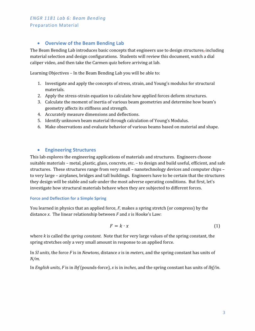
It turns out that solid materials also exhibit an elastic, spring-like response to applied forces. Figure 1a (below) shows an aluminum rod with cross-section area A and initial length L when no force is applied. The atoms in the rod are all connected to their nearest neighbors by electromagnetic forces that are "spring-like" – here shown as atoms connected by springs.
Figure 1: Aluminum Bar with and without an Applied Force
Figure 1b shows the same aluminum rod, but with two opposing forces F applied at each end. In response to the forces, the length of the aluminum bar increases (stretches) by an amount ΔL. When the forces pull outward, as shown in Figure 1b, the bar is said to be in "tension".
If both forces were reversed to push inward on the ends of the bar, the length of the bar decreases by the same amount ΔL and we would say that the bar is in "compression".
Stress, Strain and Young's Modulus
For Figure 1, the "spring-like equation" for the aluminum bar is
The proportionality constant E is called Young's modulus, or the modulus of elasticity, and has units of N/m2 (Pascals) or lbf/in2 (pounds per square inch, or simply psi).
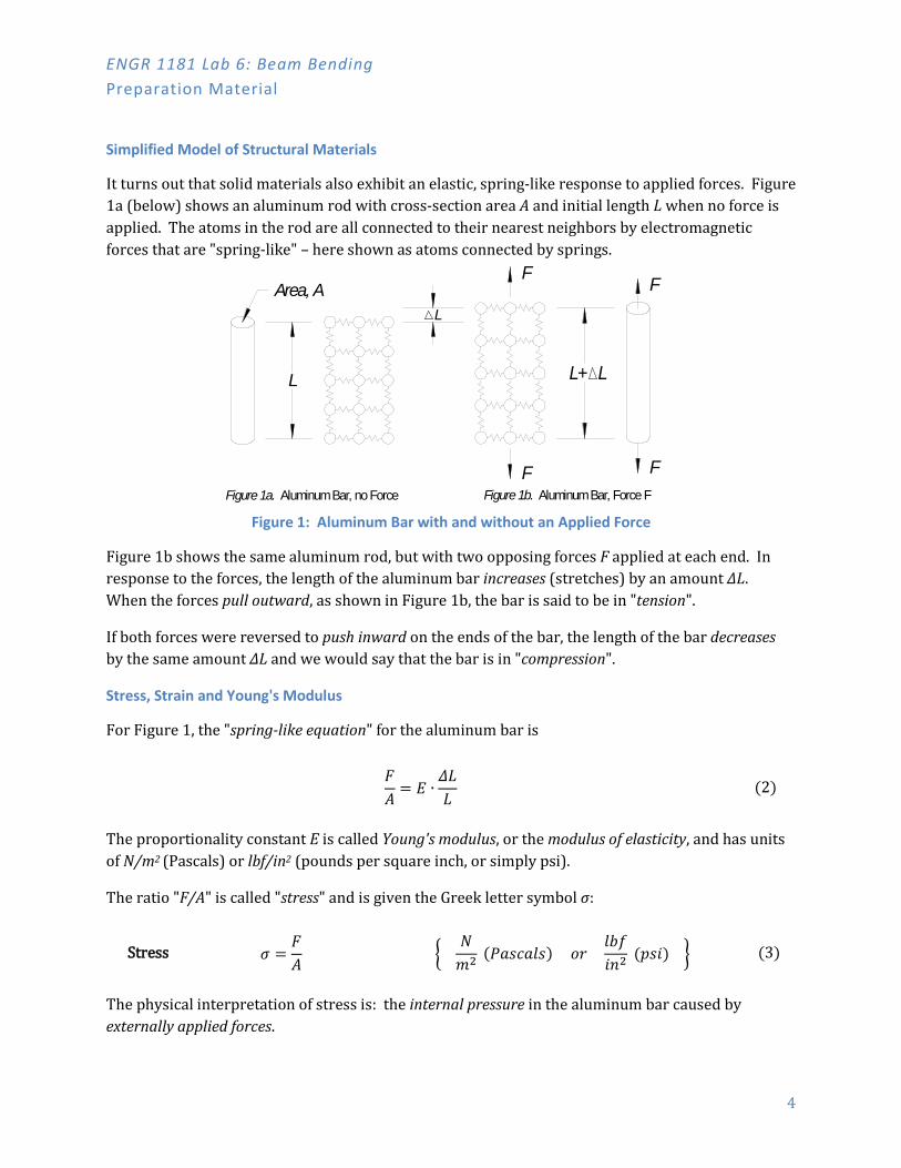
The ratio "F/A" is called "stress" and is given the Greek letter symbol σ:
The physical interpretation of stress is: the internal pressure in the aluminum bar caused by externally applied forces.
𝐹𝐹𝐴𝐴
= 𝐸𝐸 ∙𝛥𝛥𝛥𝛥𝛥𝛥
(2)
Stress 𝜎𝜎 =𝐹𝐹𝐴𝐴
� 𝑁𝑁𝑚𝑚2 (𝑃𝑃𝑃𝑃𝑃𝑃𝑃𝑃𝑃𝑃𝑃𝑃𝑃𝑃) 𝑜𝑜𝑜𝑜
𝑃𝑃𝑙𝑙𝑙𝑙𝑖𝑖𝑖𝑖2
(𝑝𝑝𝑃𝑃𝑖𝑖) � (3)
ENGR 1181 Lab 6: Beam Bending Preparation Material
5
The ratio "ΔL/L" is called "strain" (note that it has no units) and is given the Greek letter symbol ε:
Therefore, strain is the fractional elongation (or compression) of a structural member caused by applied forces. For instance, a strain of ε = 0.025 would correspond to a 2.5% increase in the length of the bar.
Substituting Equations (3) and (4) into (2) gives the fundamental "stress-strain" equation for
materials:
For most structural materials (steel, etc.), Young's modulus is very large, so large forces cause only small deformations. Have you ever been in a car on a bridge and felt the slight up-and-down motion of the bridge caused by heavy trucks moving across the bridge?
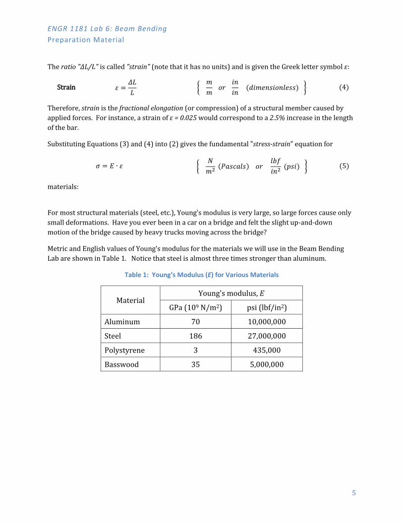
Metric and English values of Young's modulus for the materials we will use in the Beam Bending Lab are shown in Table 1. Notice that steel is almost three times stronger than aluminum.
Table 1: Young’s Modulus (E) for Various Materials
Material Young's modulus, E
GPa (109 N/m2) psi (lbf/in2)
Aluminum 70 10,000,000
Steel 186 27,000,000
Polystyrene 3 435,000
Basswood 35 5,000,000
Strain 𝜀𝜀 =𝛥𝛥𝛥𝛥𝛥𝛥
� 𝑚𝑚𝑚𝑚
𝑜𝑜𝑜𝑜 𝑖𝑖𝑖𝑖𝑖𝑖𝑖𝑖
(𝑑𝑑𝑖𝑖𝑚𝑚𝑑𝑑𝑖𝑖𝑃𝑃𝑖𝑖𝑜𝑜𝑖𝑖𝑃𝑃𝑑𝑑𝑃𝑃𝑃𝑃) � (4)
𝜎𝜎 = 𝐸𝐸 ∙ 𝜀𝜀 � 𝑁𝑁𝑚𝑚2 (𝑃𝑃𝑃𝑃𝑃𝑃𝑃𝑃𝑃𝑃𝑃𝑃𝑃𝑃) 𝑜𝑜𝑜𝑜
𝑃𝑃𝑙𝑙𝑙𝑙𝑖𝑖𝑖𝑖2
(𝑝𝑝𝑃𝑃𝑖𝑖) � (5)
ENGR 1181 Lab 6: Beam Bending Preparation Material
6
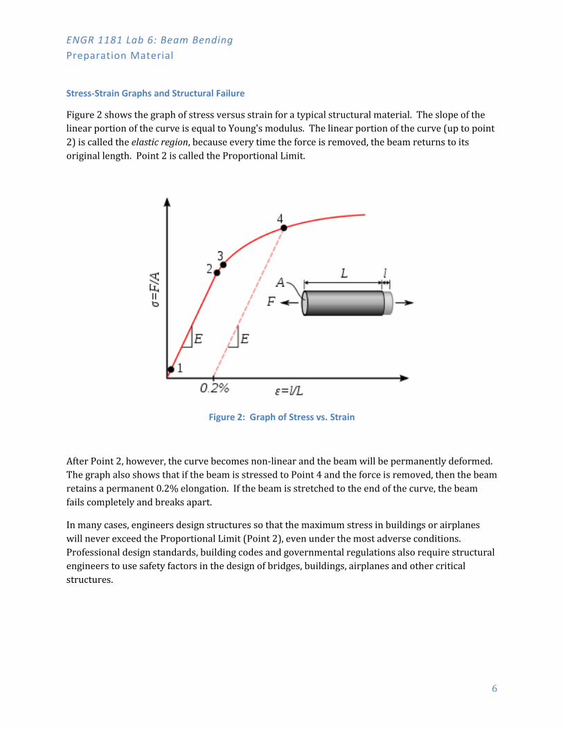
Stress-Strain Graphs and Structural Failure
Figure 2 shows the graph of stress versus strain for a typical structural material. The slope of the linear portion of the curve is equal to Young's modulus. The linear portion of the curve (up to point 2) is called the elastic region, because every time the force is removed, the beam returns to its original length. Point 2 is called the Proportional Limit.
Figure 2: Graph of Stress vs. Strain
After Point 2, however, the curve becomes non-linear and the beam will be permanently deformed. The graph also shows that if the beam is stressed to Point 4 and the force is removed, then the beam retains a permanent 0.2% elongation. If the beam is stretched to the end of the curve, the beam fails completely and breaks apart.
In many cases, engineers design structures so that the maximum stress in buildings or airplanes will never exceed the Proportional Limit (Point 2), even under the most adverse conditions. Professional design standards, building codes and governmental regulations also require structural engineers to use safety factors in the design of bridges, buildings, airplanes and other critical structures.
ENGR 1181 Lab 6: Beam Bending Preparation Material
7
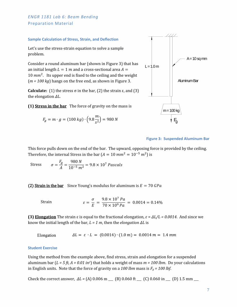
Sample Calculation of Stress, Strain, and Deflection
Let's use the stress-strain equation to solve a sample problem.
Consider a round aluminum bar (shown in Figure 3) that has an initial length 𝛥𝛥 = 1 𝑚𝑚 and a cross-sectional area 𝐴𝐴 =10 𝑚𝑚𝑚𝑚2. Its upper end is fixed to the ceiling and the weight (m = 100 kg) hangs on the free end, as shown in Figure 3.
Calculate: (1) the stress σ in the bar, (2) the strain ε, and (3) the elongation ΔL.
(1) Stress in the bar The force of gravity on the mass is
𝐹𝐹𝑔𝑔 = 𝑚𝑚 ∙ 𝑔𝑔 = (100 𝑘𝑘𝑔𝑔) ∙ �9.8𝑚𝑚𝑃𝑃2� = 980 𝑁𝑁
Figure 3: Suspended Aluminum Bar
This force pulls down on the end of the bar. The upward, opposing force is provided by the ceiling. Therefore, the internal Stress in the bar (𝐴𝐴 = 10 𝑚𝑚𝑚𝑚2 = 10−5 𝑚𝑚2) is
(2) Strain in the bar Since Young's modulus for aluminum is 𝐸𝐸 = 70 𝐺𝐺𝑃𝑃𝑃𝑃
(3) Elongation The strain ε is equal to the fractional elongation, ε = ΔL/L = 0.0014. And since we know the initial length of the bar, L = 1 m, then the elongation ΔL is
Student Exercise
Using the method from the example above, find stress, strain and elongation for a suspended aluminum bar (L = 5 ft, A = 0.01 in2) that holds a weight of mass m = 100 lbm. Do your calculations in English units. Note that the force of gravity on a 100 lbm mass is Fg = 100 lbf.
Check the correct answer, ΔL = (A) 0.006 m ___ (B) 0.060 ft ___ (C) 0.060 in ___ (D) 1.5 mm ___
Stress 𝜎𝜎 =𝐹𝐹𝑔𝑔𝐴𝐴
=980 𝑁𝑁
10−5 𝑚𝑚2 = 9.8 × 10⁷ 𝑃𝑃𝑃𝑃𝑃𝑃𝑃𝑃𝑃𝑃𝑃𝑃𝑃𝑃
Strain 𝜀𝜀 = 𝜎𝜎𝐸𝐸
= 9.8 × 10⁷ 𝑃𝑃𝑃𝑃70 × 109 𝑃𝑃𝑃𝑃
= 0.0014 = 0.14%
A = 10 sq mm
Aluminum Bar
m = 100 kg
L = 1.0 m
Fg

ENGR 1181 Lab 6: Beam Bending Preparation Material
8
• Cantilever Beams Horizontal Cantilever Beam
A cantilever beam is a structure with one end firmly anchored and the other end free to move. Figure 4 shows a cantilever beam with the beam oriented in a horizontal plane.
The free end of the beam will move down if an external force F is applied to the end. The deflection of the free end of the beam due to the applied force F depends on: (1) the dimensions of the beam (length L, width w, and thickness t), (2) Young's modulus (E) for the beam material, and (3) a geometry factor called the Moment of Inertia.
Examples of horizontal cantilevers are:
• airplane wings • diving boards • the overhanging section of the upper level deck in Ohio Stadium.
Figure 4: Horizontal Cantilever Beam
The force F causes the end of the beam to deflect downward by an amount δ. The equation to calculate the deflection δ is:
Deflection 𝛿𝛿 = 𝐹𝐹𝛥𝛥3
3𝐸𝐸𝐸𝐸 { 𝑚𝑚 𝑜𝑜𝑜𝑜 𝑖𝑖𝑖𝑖 } (6)
The Moment of Inertia, I, is a geometry factor that depends only on the cross-sectional dimensions (width w and thickness t) of the beam. For the rectangular beam shown in Figure 4, the moment of inertia is
Moment of Inertia 𝐸𝐸 = 𝑤𝑤 𝑡𝑡3
12 { 𝑚𝑚4 𝑜𝑜𝑜𝑜 𝑖𝑖𝑖𝑖4 } (7)

ENGR 1181 Lab 6: Beam Bending Preparation Material
9
Sample Calculation of Deflection
Given a rectangular aluminum beam with L = 1 m, w = 5 cm, t = 1 cm and F = 100 N, first calculate I:
Then calculate the deflection at the end of the beam (Young's modulus for aluminum is in Table 1):
Vertical Cantilever Beam
In the Beam Bending Lab, you will test vertical cantilever beams, similar to the beam in Figure 5. In the figure, the force is horizontal and the beam bends to the right.
A few familiar examples of vertical cantilevers are:
• Trees • Stop signs • Tall buildings • Wind turbine towers
On a windy day, the force of the wind is distributed over exposed surfaces and causes these structures to bend.
The Sears Tower in Chicago (now called the Willis Tower) is 110 stories and 1,450 feet tall. A 60 mph wind causes the building to bend and the top of the tower to move laterally by 6 inches. The tower's structure is designed to safely withstand the largest wind speed ever expected in Chicago.
Deflection 𝛿𝛿 = 𝐹𝐹𝛥𝛥3
3𝐸𝐸𝐸𝐸 =
(100 𝑁𝑁) (1 𝑚𝑚)3
3 (70 × 109 𝑁𝑁 𝑚𝑚2⁄ ) (8.33 × 10⁻⁸ 𝑚𝑚4) = 0.0057 𝑚𝑚 = 5.7 𝑚𝑚𝑚𝑚
Moment of Inertia 𝐸𝐸 = 𝑤𝑤 𝑡𝑡3
12 =
(0.05 𝑚𝑚)(0.01 𝑚𝑚)3
12 = 8.33 × 10⁻⁸ 𝑚𝑚4
Figure 5: Vertical Cantilever Beam

ENGR 1181 Lab 6: Beam Bending Preparation Material
10
• Lab Setup Calculations Theoretical Model of the Beam Bending Apparatus
In the beam bending apparatus, the force F is applied at a location that is a distance L = 8.75" from the fixed end of the beam, as shown in Figure 6. Also shown, the deflection of the beam is measured (by the Dial Indicator) at the location S = 7. 5" from the fixed end of the beam.
The equation that gives deflection as a function of the applied force and beam properties is:
Deflection (at location S) 𝛿𝛿 =
𝐹𝐹 𝑆𝑆2 6 𝐸𝐸 𝐸𝐸
(3𝛥𝛥 − 𝑆𝑆) (8)
Using Equation 7 and then 8, do a sample calculation for a steel beam (as used in this lab) that has the following properties:
• L = 8.75" • S = 7.5" • w = 0.50" • t = 0.125" • E = 27,000,000 lbf / in2 • F = 1.0 lbf
Then, calculate deflection:
Deflection (at location S)
𝛿𝛿 = 𝐹𝐹 𝑆𝑆2 6 𝐸𝐸 𝐸𝐸
(3𝛥𝛥 − 𝑆𝑆)
= (1.0 𝑃𝑃𝑙𝑙𝑙𝑙) (7.5 𝑖𝑖𝑖𝑖)2
6 (27,000,000 𝑃𝑃𝑙𝑙𝑙𝑙 𝑖𝑖𝑖𝑖2⁄ ) (8.138 × 10⁻⁵ 𝑖𝑖𝑖𝑖4) (3 ∙ (8.75 𝑖𝑖𝑖𝑖)− 7.5 𝑖𝑖𝑖𝑖)
𝛿𝛿 = 0.080 𝑖𝑖𝑖𝑖𝑃𝑃ℎ𝑑𝑑𝑃𝑃
Moment of Inertia: 𝐸𝐸 = 𝑤𝑤 𝑡𝑡3
12 =
(0.5 𝑖𝑖𝑖𝑖)(0.125 𝑖𝑖𝑖𝑖)3
12 = 8.138 × 10⁻⁵ 𝑖𝑖𝑖𝑖4
Figure 6: Theoretical Model of the Beam Bending Apparatus
ENGR 1181 Lab 6: Beam Bending Preparation Material
11
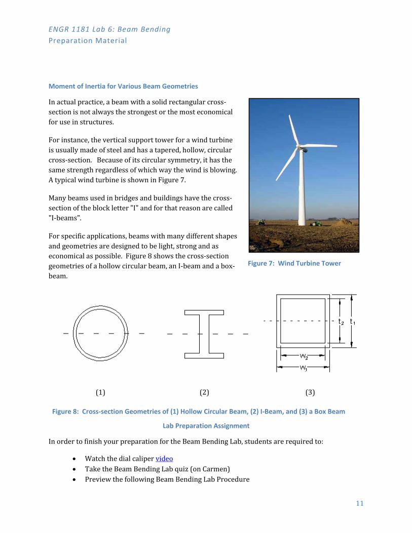
Moment of Inertia for Various Beam Geometries
In actual practice, a beam with a solid rectangular cross-section is not always the strongest or the most economical for use in structures.
For instance, the vertical support tower for a wind turbine is usually made of steel and has a tapered, hollow, circular cross-section. Because of its circular symmetry, it has the same strength regardless of which way the wind is blowing. A typical wind turbine is shown in Figure 7.
Many beams used in bridges and buildings have the cross-section of the block letter "I" and for that reason are called "I-beams".
For specific applications, beams with many different shapes and geometries are designed to be light, strong and as economical as possible. Figure 8 shows the cross-section geometries of a hollow circular beam, an I-beam and a box-beam.
(1) (2) (3)
Figure 8: Cross-section Geometries of (1) Hollow Circular Beam, (2) I-Beam, and (3) a Box Beam
Lab Preparation Assignment
In order to finish your preparation for the Beam Bending Lab, students are required to:
• Watch the dial caliper video • Take the Beam Bending Lab quiz (on Carmen) • Preview the following Beam Bending Lab Procedure
Figure 7: Wind Turbine Tower

ENGR 1181 Lab 6: Beam Bending Lab Procedure
12
Lab Procedure

ENGR 1181 Lab 6: Beam Bending Lab Procedure
13
Introduction and Background A large commercial real estate firm bought up multiple properties in the old industrial end of town. This includes some brownfields and abandoned manufacturing plants and warehouses. They believe this area will see a rebirth in the next 5-10 years and see this as a large reclamation project. Mixing old industrial space and future sustainable practices, they want to reuse as much of the material as possible. However, the exact condition of the property is not known, including soil contamination, water infiltration, building structure integrity, and reusability of materials. Your engineering firm was hired to evaluate all aspects of this project and provide guidance in possible re-use of the materials.
Your boss has asked a small group of engineers (including you) to go out and evaluate the buildings for material assessment and possible reusability. Once in the field, you identify some of the structural beams and various raw materials that were never used in the largest building, which was a metal forming plant.
Your task is to first identify this unknown material through gained lab knowledge, and then report back to the client on ways to reuse and incorporate the material in future projects. The client has asked that each engineer in your group provide their own individual conclusions and recommendations.
Photo credit: “Abandoned VI” by Jakub Kubica

ENGR 1181 Lab 6: Beam Bending Lab Procedure
14
Lab Setup: Assemble the Beam Bending Lab Kit & Open the Worksheet Working in a team of two, open the Beam Bending Lab Kit and examine the contents. If your Beam Bending Lab apparatus is not assembled, then assemble the parts to match Figure 9. The following components are included in your kit:
• Clamp – used to securely hold the fixed end of the vertical cantilever beam • Vertical Cantilever Beam – made of different sizes, shapes, and materials, including:
o Aluminum o Copper (rectangular beam) o Copper (closed square beam) o Unknown
• Dial Indicator – a precision instrument used to accurately measure beam deflection • Pulley – transmits the vertical force of the weights to a horizontal force on the beam • Weight Holder – holds up to ten weights • Extra Weights – ten weights are supplied with each lab kit (50 gm. each) • (1) a 5/32" Hex wrench (T-shaped tool)
Figure 9: Beam Bending Lab Apparatus
Let your instructor know immediately if anything is missing from the kit.
Clamp
VerticalCantilever
Beam
Dial Indicator
Pulley
WeightHolder
ExtraWeights

ENGR 1181 Lab 6: Beam Bending Lab Procedure
15
Open the Excel file called "Beam_Bending_Lab_Worksheet" located on the EEIC website and save it to your Z : Drive or to a USB memory device.
Take a minute or two and look at what is in the worksheet and how it is organized. You are going to use the worksheet to record your data and take it with you after you have finished the lab. It's always good practice to save the worksheet often!
Notice that there are places to enter data for each of Tasks 3 through 6. The cells where you are to enter data are marked with a blue background. The rest of the cells contain formulas for calculations after you enter data. Also, the first recorded task (Task 3) has a graph that will automatically plot your data as you enter it. You will eventually create a similar graph for each of the subsequent tasks.
Task 1. Measure the characteristics of the Aluminum Rectangular Beam 1.1 Locate the Aluminum Rectangular Beam. See Figure 10
that describes thickness (t) and width (w). Using the Dial Caliper, measure the t and w of the beam and enter these values into Excel worksheet, Table 1.1, cells F14 and F15.
Notice that values for distance to force (L), distance to dial indicator (S), and force (F) are already entered. Check to make sure this matches the actual set-up. Also, notice that the spreadsheet automatically calculates the Moment of Inertia (I) for the aluminum beam.
1.2 Loosen the four screws at the left end of the clamp (if necessary), and insert the aluminum
beam into the clamp. Make sure the hole in the beam is at the top and the bottom end of the aluminum beam is fully inserted into the clamp.
Gently tighten the cap screws making them just tight enough to hold the beam securely and vertically in place. Do not make them "gorilla tight".
Figure 10: Beam Measurements

ENGR 1181 Lab 6: Beam Bending Lab Procedure
16
1.3 Before the dial indicator was loaded (no weight added or placed against beam), it should have read approximately -0.010", but will be vary different indicators. Note that the small dial (in tenths of an inch) is just shy of 0 because the large dial (thousandths) is also shy of zero.
DO NOT ROTATE THE BEZEL ON THE FRONT OF THE DIAL INDICATOR. The black marker should always be in line with the plunger, as shown in Figure 11.
Once it is placed in the apparatus and the plunger is engaged on the beam, it should move to near zero or a small positive value. It’s okay that it’s not exactly zero because all of the measurements taken are relative and will be calculated based on the change from the initial “zero weight” loading. The reading shows that the plunger is engaged and in contact with a surface, as shown below:
Figure 11: Dial Indicator: Unloaded and Engaged (or “Zeroed”)
1.4 Make sure that the measuring rod on the dial indicator touches the middle of the beam, in reference to the width (w).
1.5 Feed the "eye-bolt" end of the weight holder through the hole in the beam and thread the thumb nut onto the eye-bolt thread. Also, make sure the string goes over the top of the pulley and the weight holder hangs to the right. This is shown in Figure 9.
11a: Unloaded Dial Indicator 11b: “Zero Weight” Dial Indicator
ENGR 1181 Lab 6: Beam Bending Lab Procedure
17
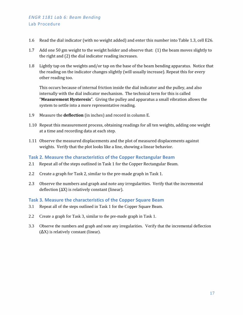
1.6 Read the dial indicator (with no weight added) and enter this number into Table 1.3, cell E26.
1.7 Add one 50 gm weight to the weight holder and observe that: (1) the beam moves slightly to the right and (2) the dial indicator reading increases.
1.8 Lightly tap on the weights and/or tap on the base of the beam bending apparatus. Notice that the reading on the indicator changes slightly (will usually increase). Repeat this for every other reading too.
This occurs because of internal friction inside the dial indicator and the pulley, and also internally with the dial indicator mechanism. The technical term for this is called "Measurement Hysteresis". Giving the pulley and apparatus a small vibration allows the system to settle into a more representative reading.
1.9 Measure the deflection (in inches) and record in column E.
1.10 Repeat this measurement process, obtaining readings for all ten weights, adding one weight at a time and recording data at each step.
1.11 Observe the measured displacements and the plot of measured displacements against weights. Verify that the plot looks like a line, showing a linear behavior.
Task 2. Measure the characteristics of the Copper Rectangular Beam 2.1 Repeat all of the steps outlined in Task 1 for the Copper Rectangular Beam.
2.2 Create a graph for Task 2, similar to the pre-made graph in Task 1.
2.3 Observe the numbers and graph and note any irregularities. Verify that the incremental deflection (ΔX) is relatively constant (linear).
Task 3. Measure the characteristics of the Copper Square Beam 3.1 Repeat all of the steps outlined in Task 1 for the Copper Square Beam.
2.2 Create a graph for Task 3, similar to the pre-made graph in Task 1.
3.3 Observe the numbers and graph and note any irregularities. Verify that the incremental deflection (ΔX) is relatively constant (linear).
ENGR 1181 Lab 6: Beam Bending Lab Procedure
18
Task 4. Measure the characteristics of the Unknown Rectangular Beam 4.1 Repeat all of the steps outlined in Task 1 for the Unknown Rectangular Beam.
4.2 Create a graph of Deflection vs. Force for the unknown rectangular beam.
4.3 Observe the numbers and graph and note any irregularities. Verify that the incremental deflection (ΔX) is relatively constant (linear).
4.4 Calculate the slope of the graph and Young’s Modulus of the unknown rectangular beam.
Task 5. Clean-Up Procedure 5.1 Remove the Cantilever Beam from the Clamp.
5.2 Leave the apparatus and dial indicator on the table.
5.3 Put items 3-6 (below) back into the plastic storage box.
Item No. Item Description Qty. 1 Beam Bending Lab Apparatus 1 2 Dial Indicator 1 3 Allen Wrench (small) 1 4 Tee-Handle Hex Driver (yellow handle) 1 5 Cantilever Beams 5 6 50-gram Weights 10
Task 6. Check-Out Policy After you have finished the lab and the clean-up procedure, have your instructor or GTA sign the “End-of-Lab Signoff” line at the end of the grading guideline (rubric). You will lose 5 points if this is not signed by your Instructor/TA.

19
Report Guidelines
20
ENGR 1181 | Lab Memo General Guidelines
Write a Lab Memo As a group of two or three (each team divided in two), write the introduction, results, and discussion parts of this lab memo according to the instructions below and grading guideline. The conclusion part must be prepared individually. For details on content and formatting, see the Technical Communications Guide on Lab Memo specifications.
Lab Specific Directions
Results & Discussion • Plot Defection vs. Applied Force for all four beams on the same graph and discuss the
results. • Calculate the Young's Modulus of the unknown rectangular beam and identify the material. • Identify the impact of the various materials and shape configurations (How is a box beam
different from a rectangular beam? How does aluminum vs. copper affect deflection? Etc.)
Conclusion & Recommendations (Individual) • Each individual engineer is requested to provide his/her own conclusion and
recommendation in this area. o Provide the client with specific recommendations, first identify the unknown
material, and then report on ways to reuse and incorporate the material in future projects.