Preparation and characterization JAAP SCI-3
6
Journal of Analytical and Applied Pyrolysis 110 (2014) 229–234 Contents lists available at ScienceDirect Journal of Analytical and Applied Pyrolysis journal h om epage: www.elsevier.com/locate/jaap Preparation and characterization of carbon foam derived from pitch and phenolic resin using a soft templating method Shameel Farhan a,∗ , Ru-Min Wang a,∗ , Hao Jiang a , Noaman Ul-Haq b a Department of Applied Chemistry, School of Science, Northwestern Polytechnical University, Youyi West Road 127, Xi’an, Shaanxi, 710072, China b School of Chemical and Materials Engineering, National University of Sciences and Technology, Islamabad, Pakistan a r t i c l e i n f o Article history: Received 30 March 2014 Accepted 11 September 2014 Available online 28 September 2014 Keywords: Carbon Foam Thermal insulation Phenolic resin Porosity a b s t r a c t Carbon foam has been developed by soft templating method with phenolic resin and coal tar pitch as matrix precursor and polyurethane (PU) foam as an organic sacrificial template. Micron sized powdered pitch was mixed well in a diluted resin and the PU foam was soaked in it. The impregnated foam was dried at 70 ◦ C for 6 h. This impregnation–stabilization (IS) process was repeated for four and six times. A slow curing cycle with hold steps at 80, 110, 140 and 2000 ◦ C was used for the sample being pressed isostatically in a steel mold. Carbonization at 800 ◦ C in a reduced and inert environment resulted in a geometric density of 0.48 and 0.60 g/cm 3 for IS cycles of four and six respectively. The carbon foam was characterized by porosity calculations, thermogravimetric analysis, compressive strength and scan- ning electron microscopy. The developed carbon foam showed an open porosity of 63–67%, compressive strength of 13.3–19.5 MPa and pore size distribution of 10–500 m. An experimental setup was designed for the testing of carbon foam as a high temperature thermal insulation. The carbon foam specimen was heated to 975 ◦ C on the one face and the other face was monitored. The experiment was repeated with a carbon-felt specimen and the insulation indices compared. The carbon foam showed a higher insulation index but lower insulation density index due to higher density than that of the carbon felt. © 2014 Elsevier B.V. All rights reserved. 1. Introduction Carbon foams are rigid and porous materials with certain attractive features like being lightweight, having high temperature stability (∼3000 ◦ C in inert atmosphere), moderate compressive strength and tailorable thermal and electrical conductivities [1–3]. Typically, carbon foams are prepared from organic precursors like phenolic resin, coal or mesophase pitches [4–7]. The precursor and the process with controlled process parameters determine the properties of the resulting foam. The template carbonization pro- cess has been regarded as the most effective approach to produce carbon foam with controlled physical and chemical properties. The development of mesoporous and macroporous, as well as micro- porous carbon foam is of great importance in many analytical applications like adsorption, separation, sieving, catalysis, purifi- cation and ion exchange etc. [8,9]. Hard templating offers a rigid and nano-casting mold to replicate in a porous interconnected network. The resulting carbon foam is very homogeneous with a ∗ Corresponding author. Tel.: +86 29 88492947. E-mail addresses: [email protected], [email protected] (S. Farhan), [email protected] (R.-M. Wang). narrow pore size distribution on a nano or micro scale. On the other hand, the soft templating method is a cooperative forma- tion of replicating agent and the organic precursor [10]. The soft template itself converts into carbon foam during carbonization of the organic precursor and hence the control of properties is some- what difficult. Impregnation of a precursor into the template, the degree of cure and the temperature are the key controls, which offer a great challenge especially for thick PU samples. The commonly used organic precursor is a phenolic resin. Carbon foam derived from phenolic resin can be used for the high-strength thermal insulations in aerospace, nuclear, cryogenics and building indus- try [11–13]. Other foam insulations like polyurethane (PU) foams, polyethylene foams and polystyrene foams are the most popular and the cost effective thermal insulations, but easy to ignite. Carbon felt is a practical solution for most of the industrial high temper- ature insulations such as degassing, brazing, annealing, sintering carburizing and graphitizing furnaces but it tears off at high gas velocities. Moreover, the thermal and mechanical properties of a carbon felt are dependent on the fiber properties, which is non- isotropic in nature. Carbon foam provides the similar insulation properties with added advantage of structural rigidity and isotropy. Ultramet prepared carbon foam by impregnating PU foam with phenolic resin and then carbonizing at high-temperature [14–16]. http://dx.doi.org/10.1016/j.jaap.2014.09.003 0165-2370/© 2014 Elsevier B.V. All rights reserved.
-
Upload
shameel-farhan -
Category
Documents
-
view
288 -
download
0
Transcript of Preparation and characterization JAAP SCI-3
Pa
Sa
b
a
ARAA
KCTPP
1
assTpapccdpacan
(
h0
Journal of Analytical and Applied Pyrolysis 110 (2014) 229–234
Contents lists available at ScienceDirect
Journal of Analytical and Applied Pyrolysis
journa l h om epage: www.elsev ier .com/ locate / jaap
reparation and characterization of carbon foam derived from pitchnd phenolic resin using a soft templating method
hameel Farhana,∗, Ru-Min Wanga,∗, Hao Jianga, Noaman Ul-Haqb
Department of Applied Chemistry, School of Science, Northwestern Polytechnical University, Youyi West Road 127, Xi’an, Shaanxi, 710072, ChinaSchool of Chemical and Materials Engineering, National University of Sciences and Technology, Islamabad, Pakistan
r t i c l e i n f o
rticle history:eceived 30 March 2014ccepted 11 September 2014vailable online 28 September 2014
eywords:arbon Foamhermal insulationhenolic resinorosity
a b s t r a c t
Carbon foam has been developed by soft templating method with phenolic resin and coal tar pitch asmatrix precursor and polyurethane (PU) foam as an organic sacrificial template. Micron sized powderedpitch was mixed well in a diluted resin and the PU foam was soaked in it. The impregnated foam wasdried at 70 ◦C for 6 h. This impregnation–stabilization (IS) process was repeated for four and six times.A slow curing cycle with hold steps at 80, 110, 140 and 2000 ◦C was used for the sample being pressedisostatically in a steel mold. Carbonization at 800 ◦C in a reduced and inert environment resulted ina geometric density of 0.48 and 0.60 g/cm3 for IS cycles of four and six respectively. The carbon foamwas characterized by porosity calculations, thermogravimetric analysis, compressive strength and scan-ning electron microscopy. The developed carbon foam showed an open porosity of 63–67%, compressive
strength of 13.3–19.5 MPa and pore size distribution of 10–500 �m. An experimental setup was designedfor the testing of carbon foam as a high temperature thermal insulation. The carbon foam specimen washeated to 975 ◦C on the one face and the other face was monitored. The experiment was repeated with acarbon-felt specimen and the insulation indices compared. The carbon foam showed a higher insulationindex but lower insulation density index due to higher density than that of the carbon felt.© 2014 Elsevier B.V. All rights reserved.
. Introduction
Carbon foams are rigid and porous materials with certainttractive features like being lightweight, having high temperaturetability (∼3000 ◦C in inert atmosphere), moderate compressivetrength and tailorable thermal and electrical conductivities [1–3].ypically, carbon foams are prepared from organic precursors likehenolic resin, coal or mesophase pitches [4–7]. The precursornd the process with controlled process parameters determine theroperties of the resulting foam. The template carbonization pro-ess has been regarded as the most effective approach to producearbon foam with controlled physical and chemical properties. Theevelopment of mesoporous and macroporous, as well as micro-orous carbon foam is of great importance in many analyticalpplications like adsorption, separation, sieving, catalysis, purifi-
ation and ion exchange etc. [8,9]. Hard templating offers a rigidnd nano-casting mold to replicate in a porous interconnectedetwork. The resulting carbon foam is very homogeneous with a∗ Corresponding author. Tel.: +86 29 88492947.E-mail addresses: [email protected], [email protected]
S. Farhan), [email protected] (R.-M. Wang).
ttp://dx.doi.org/10.1016/j.jaap.2014.09.003165-2370/© 2014 Elsevier B.V. All rights reserved.
narrow pore size distribution on a nano or micro scale. On theother hand, the soft templating method is a cooperative forma-tion of replicating agent and the organic precursor [10]. The softtemplate itself converts into carbon foam during carbonization ofthe organic precursor and hence the control of properties is some-what difficult. Impregnation of a precursor into the template, thedegree of cure and the temperature are the key controls, which offera great challenge especially for thick PU samples. The commonlyused organic precursor is a phenolic resin. Carbon foam derivedfrom phenolic resin can be used for the high-strength thermalinsulations in aerospace, nuclear, cryogenics and building indus-try [11–13]. Other foam insulations like polyurethane (PU) foams,polyethylene foams and polystyrene foams are the most popularand the cost effective thermal insulations, but easy to ignite. Carbonfelt is a practical solution for most of the industrial high temper-ature insulations such as degassing, brazing, annealing, sinteringcarburizing and graphitizing furnaces but it tears off at high gasvelocities. Moreover, the thermal and mechanical properties of acarbon felt are dependent on the fiber properties, which is non-
isotropic in nature. Carbon foam provides the similar insulationproperties with added advantage of structural rigidity and isotropy.Ultramet prepared carbon foam by impregnating PU foam withphenolic resin and then carbonizing at high-temperature [14–16].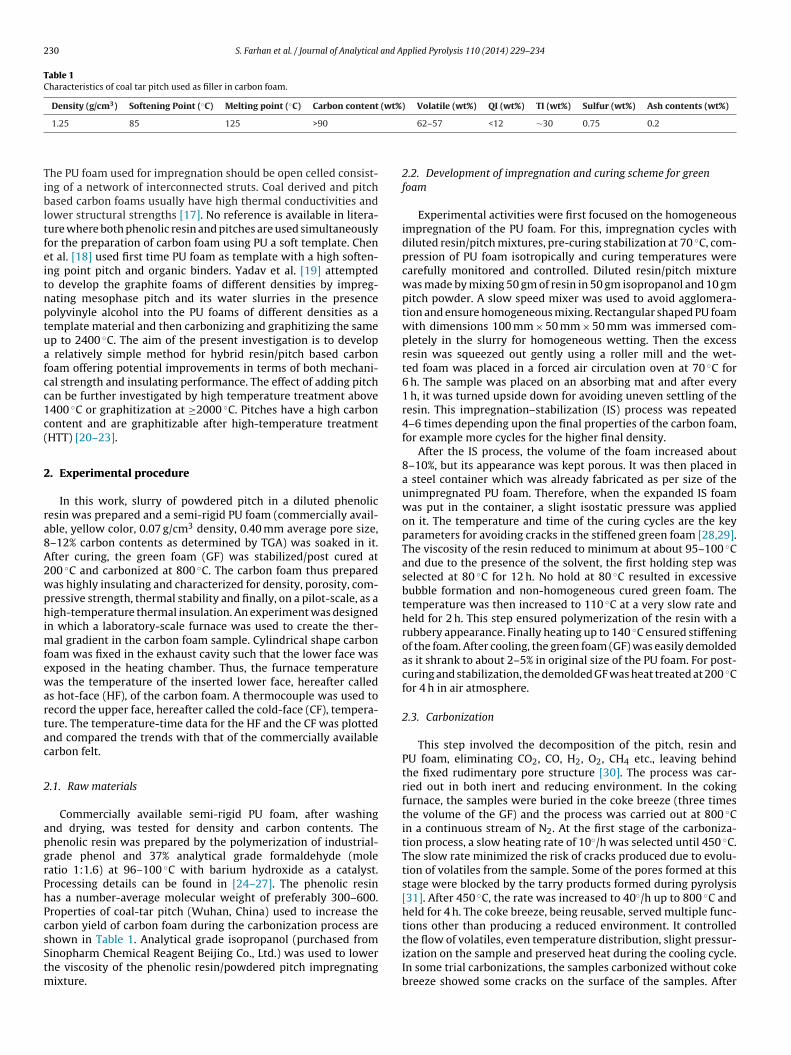
230 S. Farhan et al. / Journal of Analytical and Applied Pyrolysis 110 (2014) 229–234
Table 1Characteristics of coal tar pitch used as filler in carbon foam.
Density (g/cm3) Softening Point (◦C) Melting point (◦C) Carbon content (wt%) Volatile (wt%) QI (wt%) TI (wt%) Sulfur (wt%) Ash contents (wt%)
Tibltfeitnptuafcc1c(
2
ra8A2wphimfewartac
2
apgrPhPcsStm
1.25 85 125 >90
he PU foam used for impregnation should be open celled consist-ng of a network of interconnected struts. Coal derived and pitchased carbon foams usually have high thermal conductivities and
ower structural strengths [17]. No reference is available in litera-ure where both phenolic resin and pitches are used simultaneouslyor the preparation of carbon foam using PU a soft template. Chent al. [18] used first time PU foam as template with a high soften-ng point pitch and organic binders. Yadav et al. [19] attemptedo develop the graphite foams of different densities by impreg-ating mesophase pitch and its water slurries in the presenceolyvinyle alcohol into the PU foams of different densities as aemplate material and then carbonizing and graphitizing the samep to 2400 ◦C. The aim of the present investigation is to develop
relatively simple method for hybrid resin/pitch based carbonoam offering potential improvements in terms of both mechani-al strength and insulating performance. The effect of adding pitchan be further investigated by high temperature treatment above400 ◦C or graphitization at ≥2000 ◦C. Pitches have a high carbonontent and are graphitizable after high-temperature treatmentHTT) [20–23].
. Experimental procedure
In this work, slurry of powdered pitch in a diluted phenolicesin was prepared and a semi-rigid PU foam (commercially avail-ble, yellow color, 0.07 g/cm3 density, 0.40 mm average pore size,–12% carbon contents as determined by TGA) was soaked in it.fter curing, the green foam (GF) was stabilized/post cured at00 ◦C and carbonized at 800 ◦C. The carbon foam thus preparedas highly insulating and characterized for density, porosity, com-ressive strength, thermal stability and finally, on a pilot-scale, as aigh-temperature thermal insulation. An experiment was designed
n which a laboratory-scale furnace was used to create the ther-al gradient in the carbon foam sample. Cylindrical shape carbon
oam was fixed in the exhaust cavity such that the lower face wasxposed in the heating chamber. Thus, the furnace temperatureas the temperature of the inserted lower face, hereafter called
s hot-face (HF), of the carbon foam. A thermocouple was used toecord the upper face, hereafter called the cold-face (CF), tempera-ure. The temperature-time data for the HF and the CF was plottednd compared the trends with that of the commercially availablearbon felt.
.1. Raw materials
Commercially available semi-rigid PU foam, after washingnd drying, was tested for density and carbon contents. Thehenolic resin was prepared by the polymerization of industrial-rade phenol and 37% analytical grade formaldehyde (moleatio 1:1.6) at 96–100 ◦C with barium hydroxide as a catalyst.rocessing details can be found in [24–27]. The phenolic resinas a number-average molecular weight of preferably 300–600.roperties of coal-tar pitch (Wuhan, China) used to increase thearbon yield of carbon foam during the carbonization process are
hown in Table 1. Analytical grade isopropanol (purchased frominopharm Chemical Reagent Beijing Co., Ltd.) was used to lowerhe viscosity of the phenolic resin/powdered pitch impregnatingixture.
62–57 <12 ∼30 0.75 0.2
2.2. Development of impregnation and curing scheme for greenfoam
Experimental activities were first focused on the homogeneousimpregnation of the PU foam. For this, impregnation cycles withdiluted resin/pitch mixtures, pre-curing stabilization at 70 ◦C, com-pression of PU foam isotropically and curing temperatures werecarefully monitored and controlled. Diluted resin/pitch mixturewas made by mixing 50 gm of resin in 50 gm isopropanol and 10 gmpitch powder. A slow speed mixer was used to avoid agglomera-tion and ensure homogeneous mixing. Rectangular shaped PU foamwith dimensions 100 mm × 50 mm × 50 mm was immersed com-pletely in the slurry for homogeneous wetting. Then the excessresin was squeezed out gently using a roller mill and the wet-ted foam was placed in a forced air circulation oven at 70 ◦C for6 h. The sample was placed on an absorbing mat and after every1 h, it was turned upside down for avoiding uneven settling of theresin. This impregnation–stabilization (IS) process was repeated4–6 times depending upon the final properties of the carbon foam,for example more cycles for the higher final density.
After the IS process, the volume of the foam increased about8–10%, but its appearance was kept porous. It was then placed ina steel container which was already fabricated as per size of theunimpregnated PU foam. Therefore, when the expanded IS foamwas put in the container, a slight isostatic pressure was appliedon it. The temperature and time of the curing cycles are the keyparameters for avoiding cracks in the stiffened green foam [28,29].The viscosity of the resin reduced to minimum at about 95–100 ◦Cand due to the presence of the solvent, the first holding step wasselected at 80 ◦C for 12 h. No hold at 80 ◦C resulted in excessivebubble formation and non-homogeneous cured green foam. Thetemperature was then increased to 110 ◦C at a very slow rate andheld for 2 h. This step ensured polymerization of the resin with arubbery appearance. Finally heating up to 140 ◦C ensured stiffeningof the foam. After cooling, the green foam (GF) was easily demoldedas it shrank to about 2–5% in original size of the PU foam. For post-curing and stabilization, the demolded GF was heat treated at 200 ◦Cfor 4 h in air atmosphere.
2.3. Carbonization
This step involved the decomposition of the pitch, resin andPU foam, eliminating CO2, CO, H2, O2, CH4 etc., leaving behindthe fixed rudimentary pore structure [30]. The process was car-ried out in both inert and reducing environment. In the cokingfurnace, the samples were buried in the coke breeze (three timesthe volume of the GF) and the process was carried out at 800 ◦Cin a continuous stream of N2. At the first stage of the carboniza-tion process, a slow heating rate of 10◦/h was selected until 450 ◦C.The slow rate minimized the risk of cracks produced due to evolu-tion of volatiles from the sample. Some of the pores formed at thisstage were blocked by the tarry products formed during pyrolysis[31]. After 450 ◦C, the rate was increased to 40◦/h up to 800 ◦C andheld for 4 h. The coke breeze, being reusable, served multiple func-tions other than producing a reduced environment. It controlled
the flow of volatiles, even temperature distribution, slight pressur-ization on the sample and preserved heat during the cooling cycle.In some trial carbonizations, the samples carbonized without cokebreeze showed some cracks on the surface of the samples. After
S. Farhan et al. / Journal of Analytical and Applied Pyrolysis 110 (2014) 229–234 231
ensit
cuotd
2
mmtmc
%
V
w�FwshsauT(itlsfiouo
2
uro
Fig. 1. Carbon foam specimens with a d
arbonization, the weight loss was in the range of 50–60%, vol-me shrinkage in the range of 18–22%, and the geometric densityf 0.48 (four IS cycles) to 0.60 (six IS cycles) g/cm3. Fig. 1 showshe photograph of the cut specimens of carbon foam with differentensities.
.4. Characterization
The changes in geometric density were measured by the ratio ofass of sample to the total apparent volume. The true density waseasured using a helium gas displacement Qunatachrome Pen-
apycnometer. The true density is the mass per unit volume of theaterial, which excludes all the voids or pores. The porosity was
alculated using the following expression:
P = (�t − �a
�t) × 100 (1)
T = (�t − �a
�t�a) (2)
here %P is the bulk porosity, VT is the total pore volume, �t anda are the true and apparent densities of the samples respectively.or thermogravimetric analysis (TGA) of the sample ca 10–12 mgas placed in a platinum crucible and heated to 1000 ◦C in Ar atmo-
phere using a Perkin-Elmer PYRISI instrument. The Ar flow and theeating rate were 100 ml/min and 10 ◦C/min respectively. All thepecimens were first dried in an air-drying oven at 105 ◦C for 2 hnd cooled in a desicator. The compressive strength was measuredsing the SANS CMT 5105 (100KN) mechanical testing machine.he vertical moving speed of the loading head was 0.5 mm/mincorresponding to a very low strain rate of 5.5 × 10⁻⁴ s−1). The spec-mens were machined to 33 mm (the same diameter was used inhe thermal gradient test) in diameter and 50 mm height giving aength to diameter ratio of about 1.5. In order to avoid the dustpread on the machine, the specimens were placed in a steel pipetted with a plunger. The plunger was attached to the moving headf the machine. The morphology of the foam was examined bysing a JEOL JSM-6490LV scanning electron microscope (SEM) withperating voltage of 20 kV.
.5. Furnace insulation test
The insulation performance of the carbon foam was assessedsing a thermal gradient test. A Barnstead Thermolyne 6000 labo-atory furnace was used to heat the sample up to 975 ◦C (maximumperating temperature of the furnace) under N2 environmentat the
y of: (a) 0.48 g/cm3 and (b) 0.60 g/cm3.
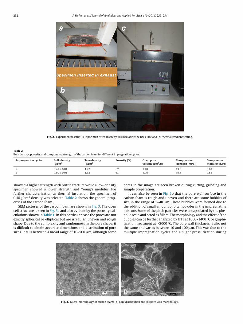
flow rate of 15 l/min. Fig. 2 shows the photographs of differentstages of the test. The exhaust gas pipe fitted on the top of the roofof the furnace was removed resulting in a cavity of diameter 33 mmand a height of 33 mm. The carbon foam was machined and fittedin the cavity to block the hole completely. Thus, one face (HF) of thecylindrical carbon foam was exposed to the heating chamber. Theopposite face (CF) leveled with the outer shell of the furnace wassealed off with an insulation brick. A hole was drilled in the centerof the insulation brick and a thermocouple was inserted in it untilit touched the specimen. After flushing the furnace with nitrogengas for 10 min, the door of the furnace was closed tightly, and theheating was turned on. At a heating rate of 11 ◦C/min, the furnacereached at the maximum temperature of 975◦C in 84 min. It washeld for 70 min and then cooled down naturally. As the HF of thecarbon foam was exposed to the heating chamber of the furnace,it also experienced the same heating profile as that of the furnace.The CF temperature was monitored with a thermocouple insertedin the insulation brick (Fig. 2(b)). The results were plotted with timescale on the x-axis. The experiment was repeated with a carbonfelt specimen (density = 0.15 ± 0.015 g/cm3, carbon content = 98.5%,ash content ≤0.25%, thermal conductivity 0.17 W/mK and tensilestrength 0.15 MPa) and compared to the results with that of thecarbon foam. The insulation and insulation density indices weredetermined by the following expressions:
I94 = t
ı(3)
ID94 = I94
�(4)
where I94 is the insulation index in min/cm at a CF temperatureof 94 ◦C, t is the time in minutes, ı is the thickness in cm, ID94 isthe specific insulation index in min-cm2/gm, and � is the densityin g/cm3.
3. Results and discussion
3.1. General properties
The volumetric density and the carbon contents of the PU foamcame out to be 0.08 g/cm3 and 9–12% respectively. The carbon yieldof phenolic resin as determined by TGA and viscosity at 25 ◦C were60% and 250 cP respectively. The density and porosity of the car-
bon foam depend on the IS cycles and slight isostatic compressionin the steel mold and were found to be in the 0.48–0.60 g/cm3range. The open porosity decreased by the increase in the den-sity. In compression testing, a higher density (0.60 g/cm3) specimen
232 S. Farhan et al. / Journal of Analytical and Applied Pyrolysis 110 (2014) 229–234
Fig. 2. Experimental setup: (a) specimen fitted in cavity, (b) insulating the back face and (c) thermal gradient testing.
Table 2Bulk density, porosity and compressive strength of the carbon foam for different impregnation cycles.
Impregnation cycles Bulk density(g/cm3)
True density(g/cm3)
Porosity (%) Open porevolume (cm3/g)
Compressivestrength (MPa)
Compressivemodulus (GPa)
7
3
ssf0e
ccesis
4 0.48 ± 0.01 1.47 66 0.60 ± 0.01 1.63 6
howed a higher strength with brittle fracture while a low-densitypecimen showed a lower strength and Young’s modulus. Forurther characterization as thermal insulation, the specimen of.48 g/cm3 density was selected. Table 2 shows the general prop-rties of the carbon foam.
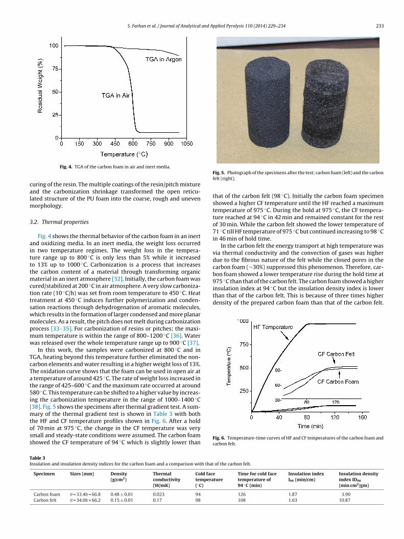
SEM pictures of the carbon foam are shown in Fig. 3. The openell structure is seen in Fig. 3a and also evident by the porosity cal-ulations shown in Table 1. In this particular case the pores are not
xactly spherical or elliptical but are irregular, uneven and roughhape. Due to the complexity and randomness in the pore shape, its difficult to obtain accurate dimensions and distribution of poreizes. It falls between a broad range of 10–500 �m, although someFig. 3. Micro-morphology of carbon foam: (a) pore
1.40 13.3 0.631.06 19.5 0.81
pores in the image are seen broken during cutting, grinding andsample preparation.
It can also be seen in Fig. 3b that the pore wall surface in thecarbon foam is rough and uneven and there are some bubbles ofsize in the range of 1–40 �m. These bubbles were formed due tothe addition of small amount of pitch powder in the impregnatingmixture. Some of the pitch particles were encapsulated by the phe-nolic resin and acted as fillers. The morphology and the effect of the
◦
bubbles can be further analyzed by HTT at 1000–1400 C or graphi-tization treatment at ≥2000 ◦C. The pore wall thickness is also notthe same and varies between 10 and 100 �m. This was due to themultiple impregnation cycles and a slight pressurization duringdistribution and (b) pore wall morphology.
S. Farhan et al. / Journal of Analytical and Applied Pyrolysis 110 (2014) 229–234 233
calm
3
aitttmcttswmpmw
TcTat5i[mtoss
insulation index at 94 ◦C but the insulation density index is lowerthan that of the carbon felt. This is because of three times higherdensity of the prepared carbon foam than that of the carbon felt.
TI
Fig. 4. TGA of the carbon foam in air and inert media.
uring of the resin. The multiple coatings of the resin/pitch mixturend the carbonization shrinkage transformed the open reticu-ated structure of the PU foam into the coarse, rough and uneven
orphology.
.2. Thermal properties
Fig. 4 shows the thermal behavior of the carbon foam in an inertnd oxidizing media. In an inert media, the weight loss occurredn two temperature regimes. The weight loss in the tempera-ure range up to 800 ◦C is only less than 5% while it increasedo 13% up to 1000 ◦C. Carbonization is a process that increaseshe carbon content of a material through transforming organic
aterial in an inert atmosphere [32]. Initially, the carbon foam wasured/stabilized at 200 ◦C in air atmosphere. A very slow carboniza-ion rate (10 ◦C/h) was set from room temperature to 450 ◦C. Heatreatment at 450 ◦C induces further polymerization and conden-ation reactions through dehydrogenation of aromatic molecules,hich results in the formation of larger condensed and more planarolecules. As a result, the pitch does not melt during carbonization
rocess [33–35]. For carbonization of resins or pitches; the maxi-um temperature is within the range of 800–1200 ◦C [36]. Wateras released over the whole temperature range up to 900 ◦C [37].
In this work, the samples were carbonized at 800 ◦C and inGA, heating beyond this temperature further eliminated the non-arbon elements and water resulting in a higher weight loss of 13%.he oxidation curve shows that the foam can be used in open air at
temperature of around 425 ◦C. The rate of weight loss increased inhe range of 425–600 ◦C and the maximum rate occurred at around80 ◦C. This temperature can be shifted to a higher value by increas-
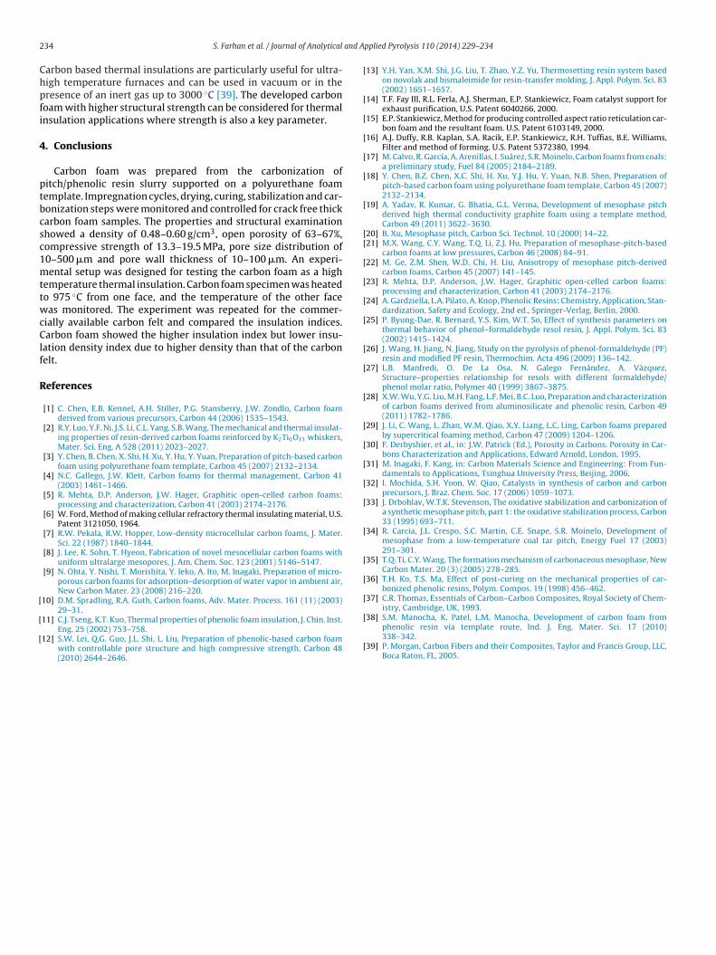
ng the carbonization temperature in the range of 1000–1400 ◦C38]. Fig. 5 shows the specimens after thermal gradient test. A sum-
ary of the thermal gradient test is shown in Table 3 with both
he HF and CF temperature profiles shown in Fig. 6. After a holdf 70 min at 975 ◦C, the change in the CF temperature was verymall and steady-state conditions were assumed. The carbon foamhowed the CF temperature of 94 ◦C which is slightly lower thanable 3nsulation and insulation density indices for the carbon foam and a comparison with that
Specimen Sizes (mm) Density(g/cm3)
Thermalconductivity(W/mK)
Cold factempera(◦C)
Carbon foam ∅ = 33.4h = 66.8 0.48 ± 0.01 0.023 94
Carbon felt ∅ = 34.0h = 66.2 0.15 ± 0.01 0.17 98
Fig. 5. Photograph of the specimens after the test; carbon foam (left) and the carbonfelt (right).
that of the carbon felt (98 ◦C). Initially the carbon foam specimenshowed a higher CF temperature until the HF reached a maximumtemperature of 975 ◦C. During the hold at 975 ◦C, the CF tempera-ture reached at 94 ◦C in 42 min and remained constant for the restof 30 min. While the carbon felt showed the lower temperature of71 ◦C till HF temperature of 975 ◦C but continued increasing to 98 ◦Cin 46 min of hold time.
In the carbon felt the energy transport at high temperature wasvia thermal conductivity and the convection of gases was higherdue to the fibrous nature of the felt while the closed pores in thecarbon foam (∼30%) suppressed this phenomenon. Therefore, car-bon foam showed a lower temperature rise during the hold time at975 ◦C than that of the carbon felt. The carbon foam showed a higher
Fig. 6. Temperature-time curves of HF and CF temperatures of the carbon foam andcarbon felt.
of the carbon felt.
eture
Time for cold facetemperature of94 ◦C (min)
Insulation indexI94 (min/cm)
Insulation densityindex ID94
(min cm2/gm)
126 1.87 3.90108 1.63 10.87
2 and A
Chpfi
4
ptbcsc1mttwcClf
R
[
[
[
[
[
[
[
[
[
[
[[
[
[
[
[
[
[
[
[
[
[
[
[
[
[
[
[
34 S. Farhan et al. / Journal of Analytical
arbon based thermal insulations are particularly useful for ultra-igh temperature furnaces and can be used in vacuum or in theresence of an inert gas up to 3000 ◦C [39]. The developed carbonoam with higher structural strength can be considered for thermalnsulation applications where strength is also a key parameter.
. Conclusions
Carbon foam was prepared from the carbonization ofitch/phenolic resin slurry supported on a polyurethane foamemplate. Impregnation cycles, drying, curing, stabilization and car-onization steps were monitored and controlled for crack free thickarbon foam samples. The properties and structural examinationhowed a density of 0.48–0.60 g/cm3, open porosity of 63–67%,ompressive strength of 13.3–19.5 MPa, pore size distribution of0–500 �m and pore wall thickness of 10–100 �m. An experi-ental setup was designed for testing the carbon foam as a high
emperature thermal insulation. Carbon foam specimen was heatedo 975 ◦C from one face, and the temperature of the other faceas monitored. The experiment was repeated for the commer-
ially available carbon felt and compared the insulation indices.arbon foam showed the higher insulation index but lower insu-
ation density index due to higher density than that of the carbonelt.
eferences
[1] C. Chen, E.B. Kennel, A.H. Stiller, P.G. Stansberry, J.W. Zondlo, Carbon foamderived from various precursors, Carbon 44 (2006) 1535–1543.
[2] R.Y. Luo, Y.F. Ni, J.S. Li, C.L. Yang, S.B. Wang, The mechanical and thermal insulat-ing properties of resin-derived carbon foams reinforced by K2Ti6O13 whiskers,Mater. Sci. Eng. A 528 (2011) 2023–2027.
[3] Y. Chen, B. Chen, X. Shi, H. Xu, Y. Hu, Y. Yuan, Preparation of pitch-based carbonfoam using polyurethane foam template, Carbon 45 (2007) 2132–2134.
[4] N.C. Gallego, J.W. Klett, Carbon foams for thermal management, Carbon 41(2003) 1461–1466.
[5] R. Mehta, D.P. Anderson, J.W. Hager, Graphitic open-celled carbon foams:processing and characterization, Carbon 41 (2003) 2174–2176.
[6] W. Ford, Method of making cellular refractory thermal insulating material, U.S.Patent 3121050, 1964.
[7] R.W. Pekala, R.W. Hopper, Low-density microcellular carbon foams, J. Mater.Sci. 22 (1987) 1840–1844.
[8] J. Lee, K. Sohn, T. Hyeon, Fabrication of novel mesocellular carbon foams withuniform ultralarge mesopores, J. Am. Chem. Soc. 123 (2001) 5146–5147.
[9] N. Ohta, Y. Nishi, T. Morishita, Y. Ieko, A. Ito, M. Inagaki, Preparation of micro-porous carbon foams for adsorption–desorption of water vapor in ambient air,New Carbon Mater. 23 (2008) 216–220.
10] D.M. Spradling, R.A. Guth, Carbon foams, Adv. Mater. Process. 161 (11) (2003)29–31.
11] C.J. Tseng, K.T. Kuo, Thermal properties of phenolic foam insulation, J. Chin. Inst.Eng. 25 (2002) 753–758.
12] S.W. Lei, Q.G. Guo, J.L. Shi, L. Liu, Preparation of phenolic-based carbon foamwith controllable pore structure and high compressive strength, Carbon 48(2010) 2644–2646.
[
[
pplied Pyrolysis 110 (2014) 229–234
13] Y.H. Yan, X.M. Shi, J.G. Liu, T. Zhao, Y.Z. Yu, Thermosetting resin system basedon novolak and bismaleimide for resin-transfer molding, J. Appl. Polym. Sci. 83(2002) 1651–1657.
14] T.F. Fay III, R.L. Ferla, A.J. Sherman, E.P. Stankiewicz, Foam catalyst support forexhaust purification, U.S. Patent 6040266, 2000.
15] E.P. Stankiewicz, Method for producing controlled aspect ratio reticulation car-bon foam and the resultant foam. U.S. Patent 6103149, 2000.
16] A.J. Duffy, R.B. Kaplan, S.A. Racik, E.P. Stankiewicz, R.H. Tuffias, B.E. Williams,Filter and method of forming. U.S. Patent 5372380, 1994.
17] M. Calvo, R. García, A. Arenillas, I. Suárez, S.R. Moinelo, Carbon foams from coals:a preliminary study, Fuel 84 (2005) 2184–2189.
18] Y. Chen, B.Z. Chen, X.C. Shi, H. Xu, Y.J. Hu, Y. Yuan, N.B. Shen, Preparation ofpitch-based carbon foam using polyurethane foam template, Carbon 45 (2007)2132–2134.
19] A. Yadav, R. Kumar, G. Bhatia, G.L. Verma, Development of mesophase pitchderived high thermal conductivity graphite foam using a template method,Carbon 49 (2011) 3622–3630.
20] B. Xu, Mesophase pitch, Carbon Sci. Technol. 10 (2000) 14–22.21] M.X. Wang, C.Y. Wang, T.Q. Li, Z.J. Hu, Preparation of mesophase-pitch-based
carbon foams at low pressures, Carbon 46 (2008) 84–91.22] M. Ge, Z.M. Shen, W.D. Chi, H. Liu, Anisotropy of mesophase pitch-derived
carbon foams, Carbon 45 (2007) 141–145.23] R. Mehta, D.P. Anderson, J.W. Hager, Graphitic open-celled carbon foams:
processing and characterization, Carbon 41 (2003) 2174–2176.24] A. Gardziella, L.A. Pilato, A. Knop, Phenolic Resins: Chemistry, Application, Stan-
dardization, Safety and Ecology, 2nd ed., Springer-Verlag, Berlin, 2000.25] P. Byung-Dae, R. Bernard, Y.S. Kim, W.T. So, Effect of synthesis parameters on
thermal behavior of phenol–formaldehyde resol resin, J. Appl. Polym. Sci. 83(2002) 1415–1424.
26] J. Wang, H. Jiang, N. Jiang, Study on the pyrolysis of phenol-formaldehyde (PF)resin and modified PF resin, Thermochim. Acta 496 (2009) 136–142.
27] L.B. Manfredi, O. De La Osa, N. Galego Fernández, A. Vázquez,Structure–properties relationship for resols with different formaldehyde/phenol molar ratio, Polymer 40 (1999) 3867–3875.
28] X.W. Wu, Y.G. Liu, M.H. Fang, L.F. Mei, B.C. Luo, Preparation and characterizationof carbon foams derived from aluminosilicate and phenolic resin, Carbon 49(2011) 1782–1786.
29] J. Li, C. Wang, L. Zhan, W.M. Qiao, X.Y. Liang, L.C. Ling, Carbon foams preparedby supercritical foaming method, Carbon 47 (2009) 1204–1206.
30] F. Derbyshier, et al., in: J.W. Patrick (Ed.), Porosity in Carbons. Porosity in Car-bons Characterization and Applications, Edward Arnold, London, 1995.
31] M. Inagaki, F. Kang, in: Carbon Materials Science and Engineering: From Fun-damentals to Applications, Tsinghua University Press, Beijing, 2006.
32] I. Mochida, S.H. Yoon, W. Qiao, Catalysts in synthesis of carbon and carbonprecursors, J. Braz. Chem. Soc. 17 (2006) 1059–1073.
33] J. Drbohlav, W.T.K. Stevenson, The oxidative stabilization and carbonization ofa synthetic mesophase pitch, part 1: the oxidative stabilization process, Carbon33 (1995) 693–711.
34] R. Carcia, J.L. Crespo, S.C. Martin, C.E. Snape, S.R. Moinelo, Development ofmesophase from a low-temperature coal tar pitch, Energy Fuel 17 (2003)291–301.
35] T.Q. Ti, C.Y. Wang, The formation mechanism of carbonaceous mesophase, NewCarbon Mater. 20 (3) (2005) 278–285.
36] T.H. Ko, T.S. Ma, Effect of post-curing on the mechanical properties of car-bonized phenolic resins, Polym. Compos. 19 (1998) 456–462.
37] C.R. Thomas, Essentials of Carbon–Carbon Composites, Royal Society of Chem-istry, Cambridge, UK, 1993.
38] S.M. Manocha, K. Patel, L.M. Manocha, Development of carbon foam fromphenolic resin via template route, Ind. J. Eng. Mater. Sci. 17 (2010)338–342.
39] P. Morgan, Carbon Fibers and their Composites, Taylor and Francis Group, LLC,Boca Raton, FL, 2005.