PRELIMINARY PLANS - Standout Arts · XXXX-XXX-XXX, B1802 2 of 3 Full Depth Pavement Removal Mill...
4
Transcript of PRELIMINARY PLANS - Standout Arts · XXXX-XXX-XXX, B1802 2 of 3 Full Depth Pavement Removal Mill...
Approved:
c
Recommended for Approval:
District Project Development Engineer
Date:
District Administrator
_ _ _ _ _ _ _ _ _ _ _ _ _ _ _ _ _ _ _ _ _ _ _ _ _ _ _ _ _ _ _ _ _ _ _ _
_ _ _ _ _ _ _ _ _ _ _ _ _ _ _ _ _ _ _ _ _ _ _ _ _ _ _ _
Date
Date
OVER HAWKSBILL CREEK
FOR CONSTRUCTION OF BRIDGE
THESE PLANS NOT TO BE USED
PRELIMINARY PLANS
REVISIONS
For Table of Revisions,
see Sheet 2.
No. Description Date
Ahmad W. Faqiri
Heather B. Jones
Consultant
COORDINATED:
SUPERVISED:
DESIGNED:
DRAWN:
CHECKED:
PLANS BY:
STRUCTURAL ENGINEER
CHANTILLY, VA
PENNONI ASSOCIATES, INC.
Heather B. Jones
PROPOSED BRIDGE REPLACEMENT OF
RTE. 211 BUSINESS (WEST MAIN STREET)
_ _ _ _ _ _ _ _ _ _ 2014, Commonwealth of Virginia
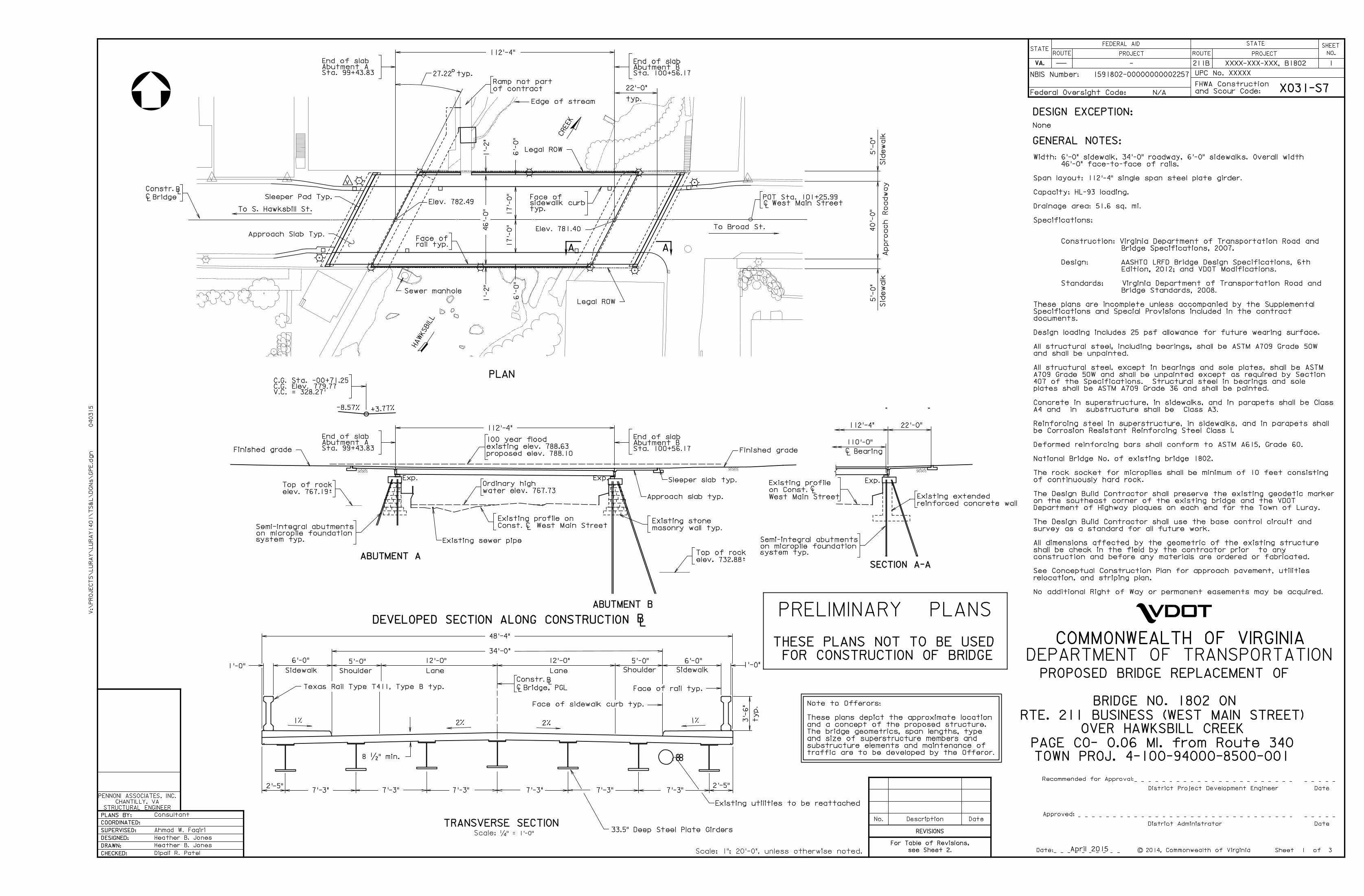
GENERAL NOTES:
DESIGN EXCEPTION:
traffic are to be developed by the Offeror.
substructure elements and maintenance of
and size of superstructure members and
The bridge geometrics, span lengths, type
and a concept of the proposed structure.
These plans depict the approximate location
Note to Offerors:
1’-
2"
17’-
0"
HA
WKS
BIL
L
CREE
K
Approach Slab Typ.
112’-4"
To S. Hawksbill St.
46’-
0"
6’-
0"
17’-
0"
6’-
0"
1’-
2"
Edge of stream
Sheet 1 of 3
Sleeper Pad Typ.
typ.sidewallk curbFace of
rail typ.Face of
Finished grade
Exp.
LC
Exp.
112’-4"
Const. West Main Street
Existing profile on
ABUTMENT A
ABUTMENT B
Sleeper slab typ.
DEVELOPED SECTION ALONG CONSTRUCTION LB
LC
Exp.
reinforced concrete wall
Existing extended
2’-5"7’-3"
8 �" min.
2% 2%
Face of sidewalk curb typ.
Sidewalk
6’-0"
Lane
12’-0"
Lane
12’-0" 5’-0"
ShoulderSidewalk
6’-0"1’-0"
5’-0"
Shoulder
48’-4"
1%
Face of rail typ.
1’-0"
3’-
6"
ty
p.
7’-3" 7’-3"2’-5"
7’-3"7’-3"7’-3"
1%
�" = 1’-0"Scale:
TRANSVERSE SECTION
SECTION A-A
West Main Street
on Const.
Existing profile
PAGE CO- 0.06 MI. from Route 340
PLAN
-8.57% +3.77%
Sta. 99+43.83Abutment AEnd of slab
Sta. 100+56.17Abutment BEnd of slab
Sta. 100+56.17Abutment BEnd of slab
Sta. 99+43.83Abutment AEnd of slab
V.C. = 328.27’C.G. Elev. 779.77C.G. Sta. -00+71.25
Scale: 1": 20’-0", unless otherwise noted.
Texas Rail Type T411, Type B typ.
BRIDGE NO. 1802 ON
040315
V:\
PR
OJ
EC
TS\
LU
RA
Y\
LU
RA
Y1401\
TS
&L\
DG
Ns\
GP
E.d
gn
Elev. 782.49
Elev. 781.40
LC
o27.22 typ.
LBConstr.
LC Bridge
LB
LC
Constr.
Bridge, PGL
22’-0"
typ.
water elev. 767.73
Ordinary high
Sewer manhole
A A
112’-4"
110’-0"
BearingLC
22’-0"
of contract
Ramp not part
Existing utilities to be reattached
Dipali R. Patel
33.5" Deep Steel Plate Girders
Approach
Road
way
40’-
0"
5’-
0"
Sid
ewalk
Sid
ewalk
5’-
0"
Legal ROW
elev. 732.88~
Top of rock
34’-0"
Semi-integral abutments
on micropile foundationsystem typ.
West Main StreetPOT Sta. 101+25.99
Legal ROW
Semi-integral abutments
on micropile foundationsystem typ.
proposed elev. 788.10
existing elev. 788.63
100 year flood
Existing sewer pipe
masonry wall typ.
Existing stone
No additional Right of Way or permanent easements may be acquired.
relocation, and striping plan.
See Conceptual Construction Plan for approach pavement, utilities
construction and before any materials are ordered or fabricated.
shall be check in the field by the contractor prior to any
All dimensions affected by the geometric of the existing structure
survey as a standard for all future work.
The Design Build Contractor shall use the base control circuit and
Department of Highway plaques on each end for the Town of Luray.
on the southeast corner of the existing bridge and the VDOT
The Design Build Contractor shall preserve the existing geodetic marker
of continuously hard rock.
The rock socket for micropiles shall be minimum of 10 feet consisting
National Bridge No. of existing bridge 1802.
Deformed reinforcing bars shall conform to ASTM A615, Grade 60.
be Corrosion Resistant Reinforcing Steel Class I.
Reinforcing steel in superstructure, in sidewalks, and in parapets shall
A4 and in substructure shall be Class A3.
Concrete in superstructure, in sidewalks, and in parapets shall be Class
plates shall be ASTM A709 Grade 36 and shall be painted.
407 of the Specifications. Structural steel in bearings and sole
A709 Grade 50W and shall be unpainted except as required by Section
All structural steel, except in bearings and sole plates, shall be ASTM
and shall be unpainted.
All structural steel, including bearings, shall be ASTM A709 Grade 50W
Design loading includes 25 psf allowance for future wearing surface.
documents.
Specifications and Special Provisions included in the contract
These plans are incomplete unless accompanied by the Supplemental
Bridge Standards, 2008.
Standards: Virginia Department of Transportation Road and
Edition, 2012; and VDOT Modifications.
Design: AASHTO LRFD Bridge Design Specifications, 6th
Bridge Specifications, 2007.
Construction: Virginia Department of Transportation Road and
Specifications:
Drainage area: 51.6 sq. mi.
Capacity: HL-93 loading.
Span layout: 112’-4" single span steel plate girder.
46’-0" face-to-face of rails.
Width: 6’-0" sidewalk, 34’-0" roadway, 6’-0" sidewalks. Overall width
To Broad St.
April 2015
COMMONWEALTH OF VIRGINIA
DEPARTMENT OF TRANSPORTATION
TOWN PROJ. 4-100-94000-8500-001
ROUTE
FEDERAL AID
PROJECT ROUTE
STATE SHEET
NO.
and Scour Code:
FHWA Construction
UPC No.
VA.
STATE
Federal Oversight Code:
NBIS Number:
1
XXXXX
211B XXXX-XXX-XXX, B1802
XO31-S7
1591802-00000000002257
N/A
-
PROJECT
None
Finished grade
elev. 767.19~
Top of rock
Approach slab typ.
VV VV

Date Plan No. Sheet No.Designed: ...........
Drawn: ................
Checked: ............2013, Commonwealth of Virginiac
No. Description Date
STRUCTURE AND BRIDGE DIVISION
COMMONWEALTH OF VIRGINIA
DEPARTMENT OF TRANSPORTATION
Revisions
ROUTE
FEDERAL AID
PROJECT ROUTE PROJECT
STATE SHEET
NO.
VA.
STATEROUTE
FEDERAL AID
PROJECT ROUTE PROJECT
STATE SHEET
NO.
VA.
STATE
4/29/2015
XXXX
HBJ
HBJ
AWF
2
April 2015STRUCTURAL ENGINEER
CHANTILLY, VA
PENNONI ASSOCIATES, INC.
XXXX-XXX-XXX, B1802
2 of 3
Full Depth Pavement Removal
Mill and overlay
LEGEND
CONCEPTUAL CONSTRUCTION PLAN
NOTES:
Repair curb, gutter and sidewalk
HA
WKS
BIL
L
CREE
K
PAVEMENT PLAN
Scale : 1"=30’-0", unless otherwise noted.
1" = 10’-0"Scale:
Relocate light pole
Install approach inlet
Relocate light pole
Relocate valve
approach inlet
Install
Install ADA ramp
Install crosswalk
Relocate light pole
approach inlet
Install Install ADA ramp
Relocate light pole
APPROACH WORK
requirements.
conditions and modify as per VDOT
For signing and striping, restore existing
- approach lighting relocation.
crosswalks
- replacement of existing ADA ramps to
- replacement of existing crosswalks
- approach curb repair
- approach sidewalk repair
- full depth pavement replacement
- mill and overlay
items:
town, and other criterias for the following
designed in accordance to VDOT, AASHTO,
Limits shown are conceptual only and shall be
97+00 98+00 99+00 100+00 101+00
100+0099+00
101+00
Vo
gt
Pla
ce
So
uth
Ha
wksbill
Street
North
Ha
wksbill
Street
(Ro
ute 340
Busin
ess)
North
Broad
Street
(Route 211 Business)
West Main Street
160’-0"~
Bridge Limits
220’-0"~
Pavement Repair Limits
47’-0"~
Pavement
Repair LimitsSta. 97+02.76~Start of pavement repair
Sta. 101+31.60~End of pavement repair
So
uth
Broad
Street
Ruffner Plaza
VVV
V
VV V
V
V
V
V
VV
HJones
Polygon
HJones
Polygon