PRELIMINARY DETERMINATION SUMMARY EXXON CORPORATION...
32
PRELIMINARY DETERMINATION SUMMARY EXXON CORPORATION Permit No. 3452/PSD-TX-302M1 I. Applicant Exxon Corporation P.O. Box 100 Baytown, Texas 77522 II. Project Location The Exxon Baytown Olefins Plant is located at 3525 Decker Drive in Baytown, Harris County, Texas, Latitude 29°45' 22" and Longitude 095°00' 50". III. Project Description The Exxon Baytown Olefins Plant will be expanded through the addition of six new cracking furnaces. This will increase authorized ethylene production capacity from 2.7 billion pounds per year to 4.3 billion pounds per year. IV. Emissions Emission increases associated with this project are 401.1 tons per year (TPY) nitrogen oxides (NO x ), 122.2 TPY carbon monoxide (CO), 30.7 TPY particulate matter less than 10 microns in diameter (PM 10 ), and 27.7 TPY volatile organic compounds (VOC). V. Prevention of Significant Deterioration (PSD) Applicability Because of contemporaneous reductions in emissions, the Company nets out of federal new source review with regard to NO x and VOC. PSD review is required with regard to CO and PM 10 . Harris County is designated as non-attainment for ozone (VOC and NO x ), and attainment for all other pollutants (NO x , CO, PM 10 , and sulfur dioxide). VI. Best Available Control Technology (BACT) Each furnace will have two emission points: a combustion stack and a decoke drum vent. Fuel fired in the furnaces will be limited to natural gas, plant fuel gas, and process off gases only. The Company does not intend to fire liquid or solid fuels. Accordingly, products of combustion-related particulate matter emissions will be low. Best Available Control Technology for CO control is good furnace combustion. Permit CO emission limits are based on 10 ppmv for the combustion stacks. The decoke drum has a wet cyclone designed to control particulate matter during decoking. Wet cyclones provide 93.7 percent removal of total suspended particulate. Best Available Control Technology is applied.
Transcript of PRELIMINARY DETERMINATION SUMMARY EXXON CORPORATION...

PRELIMINARY DETERMINATION SUMMARY EXXON CORPORATION Permit No. 3452/PSD-TX-302M1 I. Applicant
Exxon Corporation P.O. Box 100 Baytown, Texas 77522
II. Project Location
The Exxon Baytown Olefins Plant is located at 3525 Decker Drive in Baytown, Harris County, Texas, Latitude 29°45' 22" and Longitude 095°00' 50".
III. Project Description
The Exxon Baytown Olefins Plant will be expanded through the addition of six new cracking furnaces. This will increase authorized ethylene production capacity from 2.7 billion pounds per year to 4.3 billion pounds per year.
IV. Emissions
Emission increases associated with this project are 401.1 tons per year (TPY) nitrogen oxides (NOx), 122.2 TPY carbon monoxide (CO), 30.7 TPY particulate matter less than 10 microns in diameter (PM10), and 27.7 TPY volatile organic compounds (VOC).
V. Prevention of Significant Deterioration (PSD) Applicability
Because of contemporaneous reductions in emissions, the Company nets out of federal new source review with regard to NOx and VOC. PSD review is required with regard to CO and PM10. Harris County is designated as non-attainment for ozone (VOC and NOx), and attainment for all other pollutants (NOx, CO, PM10, and sulfur dioxide).
VI. Best Available Control Technology (BACT)
Each furnace will have two emission points: a combustion stack and a decoke drum vent. Fuel fired in the furnaces will be limited to natural gas, plant fuel gas, and process off gases only. The Company does not intend to fire liquid or solid fuels. Accordingly, products of combustion-related particulate matter emissions will be low. Best Available Control Technology for CO control is good furnace combustion. Permit CO emission limits are based on 10 ppmv for the combustion stacks. The decoke drum has a wet cyclone designed to control particulate matter during decoking. Wet cyclones provide 93.7 percent removal of total suspended particulate. Best Available Control Technology is applied.
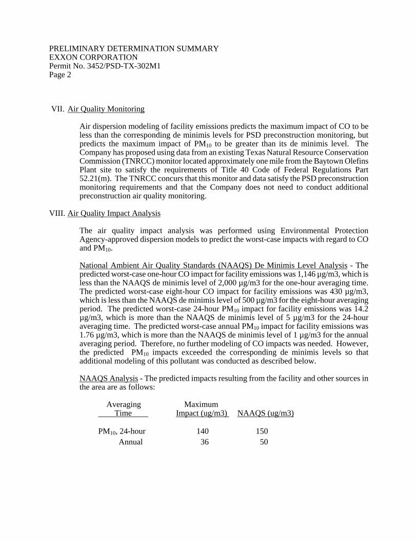
PRELIMINARY DETERMINATION SUMMARY EXXON CORPORATION Permit No. 3452/PSD-TX-302M1 Page 2 VII. Air Quality Monitoring
Air dispersion modeling of facility emissions predicts the maximum impact of CO to be less than the corresponding de minimis levels for PSD preconstruction monitoring, but predicts the maximum impact of PM10 to be greater than its de minimis level. The Company has proposed using data from an existing Texas Natural Resource Conservation Commission (TNRCC) monitor located approximately one mile from the Baytown Olefins Plant site to satisfy the requirements of Title 40 Code of Federal Regulations Part 52.21(m). The TNRCC concurs that this monitor and data satisfy the PSD preconstruction monitoring requirements and that the Company does not need to conduct additional preconstruction air quality monitoring.
VIII. Air Quality Impact Analysis
The air quality impact analysis was performed using Environmental Protection Agency-approved dispersion models to predict the worst-case impacts with regard to CO and PM10.
National Ambient Air Quality Standards (NAAQS) De Minimis Level Analysis - The predicted worst-case one-hour CO impact for facility emissions was 1,146 µg/m3, which is less than the NAAQS de minimis level of 2,000 µg/m3 for the one-hour averaging time. The predicted worst-case eight-hour CO impact for facility emissions was 430 µg/m3, which is less than the NAAQS de minimis level of 500 µg/m3 for the eight-hour averaging period. The predicted worst-case 24-hour PM10 impact for facility emissions was 14.2 µg/m3, which is more than the NAAQS de minimis level of 5 µg/m3 for the 24-hour averaging time. The predicted worst-case annual PM10 impact for facility emissions was 1.76 µg/m3, which is more than the NAAQS de minimis level of 1 µg/m3 for the annual averaging period. Therefore, no further modeling of CO impacts was needed. However, the predicted PM10 impacts exceeded the corresponding de minimis levels so that additional modeling of this pollutant was conducted as described below.
NAAQS Analysis - The predicted impacts resulting from the facility and other sources in the area are as follows:
Averaging Maximum Time Impact (ug/m3) NAAQS (ug/m3) PM10, 24-hour 140 150 Annual 36 50

PRELIMINARY DETERMINATION SUMMARY EXXON CORPORATION Permit No. 3452/PSD-TX-302M1 Page 3
PSD Increment Analysis - The degree of PSD increment predicted to be consumed by the facility and other increment consuming sources in the area is as follows:
Maximum Maximum
Averaging Increment Allowable Time Consumed (ug/m3) Increment (ug/m3)
PM10, 24-hour 16 30 Annual 2 17
IX. Additional Impact Analysis
The nearest PSD Class I Area is Breton National Wilderness Area in Louisiana. However, this park is over 500 kilometers from the project site. No negative impacts from this facility are predicted for the park. This is an expansion of an existing facility; therefore, no significant growth in the population or significant change in the environmental impacts are expected, and no adverse impacts on soils or vegetation are anticipated.
X. Conclusions
The TNRCC analysis of the permit application indicates that this source will not endanger NAAQS and will meet BACT requirements. In addition, there will be no adverse effects on soils, vegetation, or visibility. The distance to the nearest Class I area is sufficient to preclude any adverse impacts from this major source. Therefore, the TNRCC Executive Director proposes a preliminary determination of approval for Exxon Corporation to expand their Baytown Olefins Plant.
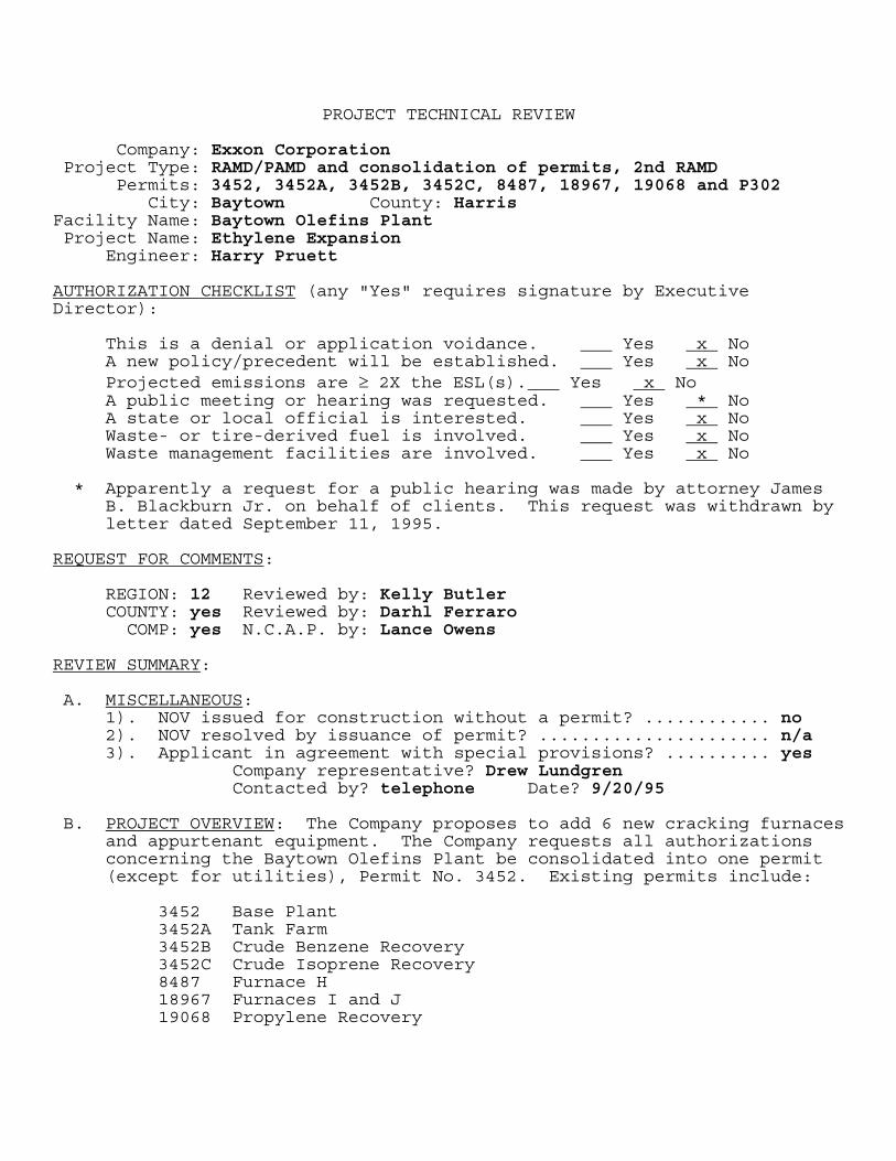
PROJECT TECHNICAL REVIEW Company: Exxon Corporation Project Type: RAMD/PAMD and consolidation of permits, 2nd RAMD Permits: 3452, 3452A, 3452B, 3452C, 8487, 18967, 19068 and P302
City: Baytown County: Harris Facility Name: Baytown Olefins Plant Project Name: Ethylene Expansion Engineer: Harry Pruett AUTHORIZATION CHECKLIST (any "Yes" requires signature by Executive Director):
This is a denial or application voidance. Yes x No A new policy/precedent will be established. Yes x No Projected emissions are ≥ 2X the ESL(s). Yes x No A public meeting or hearing was requested. Yes * No A state or local official is interested. Yes x No Waste- or tire-derived fuel is involved. Yes x No Waste management facilities are involved. Yes x No
* Apparently a request for a public hearing was made by attorney James
B. Blackburn Jr. on behalf of clients. This request was withdrawn by letter dated September 11, 1995.
REQUEST FOR COMMENTS: REGION: 12 Reviewed by: Kelly Butler COUNTY: yes Reviewed by: Darhl Ferraro COMP: yes N.C.A.P. by: Lance Owens REVIEW SUMMARY: A. MISCELLANEOUS:
1). NOV issued for construction without a permit? ............ no 2). NOV resolved by issuance of permit? ...................... n/a 3). Applicant in agreement with special provisions? .......... yes
Company representative? Drew Lundgren Contacted by? telephone Date? 9/20/95
B. PROJECT OVERVIEW: The Company proposes to add 6 new cracking furnaces
and appurtenant equipment. The Company requests all authorizations concerning the Baytown Olefins Plant be consolidated into one permit (except for utilities), Permit No. 3452. Existing permits include:
3452 Base Plant 3452A Tank Farm 3452B Crude Benzene Recovery 3452C Crude Isoprene Recovery 8487 Furnace H 18967 Furnaces I and J 19068 Propylene Recovery

There is a concurrent RAMD of Permit No. 3452 on Cracking Furnace "B" to authorize it's repair following a fire which damaged part of the facility.
C. PROCESS DESCRIPTION: Thermal cracking of hydrocarbons in the presence
of steam. Cracking is followed by cooling, fractionation, and product recovery. Feedstock for the new furnaces will be 100% ethane or a 70/30 ethane/propane mixture. Unreacted ethane will be recovered and recycled to extinction. The major end product is ethylene. Other products include propylene, butadiene, hydrogen, methane, ethane and propane.
D. SOURCES AND CONTROLS: Control of NOx emissions from the six new
cracking furnaces will be accomplished by burner design, staged air combustion, and flue gas recirculation. The Company will install and operate a NOx CEMS or PEMS on the new furnaces. They represent NOx emissions at 0.06 #/MMBTU on an annual average basis, and 0.08 #/MMBTU daily maximum. Design and emission factors are based on proprietary Company models. These furnaces will also be used intermittently to dispose of certain facility off gases.
These existing tanks are affected by subject project: ZTK-06, -07 and -08. They are currently regulated by Permit No. 3452A. In the case of ZTK-06, VOC emission rates will not change. Emission rates will increase for ZTK-07 and -08.
These new tanks will be IFRs: XZTK-04, -05, and -06. These are in order: oily sludge, wastewater equalization, and spent caustic.
These new tanks will be FXs: XKL-01, XLL-03, XVL-02, XZL-03, XZLK-16, XZTK-07, -08, -11, and -13. Of these two will contain VOCs with a vapor pressure of more than 0.5 psia; each will have a capacity of only 200 gallons.
These new tanks will vent to a control device: Tanks XZTK -01, -02, -03, XZTD12, and XZD-10. These are in order: slop oil #1, slop oil #2, CPI sludge, DMS storage, and alcohol storage. Other new emission points include a flare (EPN FLAREX), a 600 HP diesel powered emergency generator (EPN XZL16), a biological oxidation unit (EPN WWTBIOX), and a cooling tower (EPN COOLTWRX).
Project emissions total:
TPY
NOx 401.1 CO 122.2 VOC 27.7 PM10 30.7 SO2 nil
The Company is presently operating a 28 MID fugitive monitoring program at most of the related facilities. (The facilities covered by Permit Nos 3452B, 8487 and 18967 do not have 28 MID programs). They have requested that a 28 VHP program be substituted, however, with a

leak definition of 500 ppmv for pump and compressor seals (which means that emission rates do not change for existing components currently in 28 MID programs). Since current BACT would impose a 28 VHP program in this case, and since inclusion of a 28 MID program in Permit No. 3452 and the other related permits was not impacts-driven, this is allowable. It is the Company's desire to have provision for skip option.
The Company proposes to modify the LDAR program with implementation of this project to include all flanges in instrument monitoring. This will result in significant emission reductions.
In order to provide reductions in NOx emissions sufficient for the Company to net out of federal NSR review for NOx, the Company will begin steam injection of existing Furnaces A, C, D, E, F, G and H, as part of this project. Steam reduces flame temperature and this means that less NOx is formed. The Company had previously tested this technology on two of these furnaces and had submitted documentation of these reductions and a correlation of the NOx emission factor as a function of pounds of steam injected per pound of dry combustion air.
2nd RAMD - Furnace B Repair (Record No. 37703) - Repair of fire related damage will give the Company an opportunity to reduce NOx emissions from this furnace. The NOx emission factor will drop from 0.146 to 0.080 lbs NOx per MMBTU. Emission rates of other pollutants are not affected.
E. BACT: The six new furnaces will be designed for low NOx emissions and
either a CEMS or PEMS for continuous NOx monitoring. The furnace decoking vents will be controlled by wet cyclones for 93.7% PM removal. The new flare will meet 40 CFR 60.18. The Company will operate appropriate fugitive monitoring programs. The storage tanks meet 31M provisions. BACT is applied.
F. IMPACTS EVALUATION: See the attached IEF. G. SAMPLING AND TESTING REQUIRED: NOx CEMS or PEMS on each new furnace.
Also, appropriate stack sampling of new and existing furnaces. H. FEDERAL PROGRAM APPLICABILITY: PSD? yes NON-ATTAIN REVIEW? no NSPS? yes Subpart: A, K, Kb, VV, NNN, RRR NESHAPS? yes Subpart: A, J, V, FF
Remarks: NSPS Subpart YYY applies to this facility upon promulgation. I. PUBLIC NOTICE RESULTS: Apparently a request for a public hearing was
made by attorney James B. Blackburn Jr. on behalf of clients. This request was withdrawn by letter dated September 11, 1995. No other letters were received.
J. COMMENTS: Of the existing furnaces, four are considered to operate
with controlled NOx emissions: I, J, O and Q. The remainder operate

in uncontrolled mode; however, Furnace B was recently damaged by a fire and, as repaired, will operate in controlled mode.
All of the following operating permits were issued on 2/1/82: 3452, 3452A, 3452B, 3452C. These permits (and 8487) probably should have been issued as a single operating permit in 1982.
Permit Engineer Date: Section Chief/Backup Engineer Date:
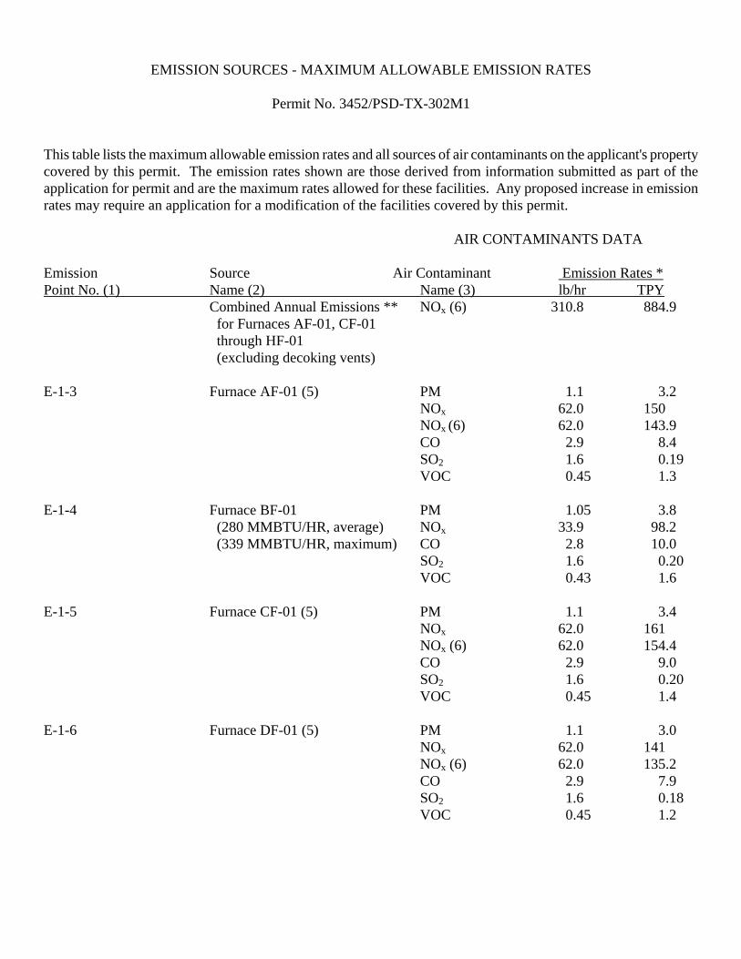
EMISSION SOURCES - MAXIMUM ALLOWABLE EMISSION RATES Permit No. 3452/PSD-TX-302M1 This table lists the maximum allowable emission rates and all sources of air contaminants on the applicant's property covered by this permit. The emission rates shown are those derived from information submitted as part of the application for permit and are the maximum rates allowed for these facilities. Any proposed increase in emission rates may require an application for a modification of the facilities covered by this permit.
AIR CONTAMINANTS DATA Emission Source Air Contaminant Emission Rates * Point No. (1) Name (2) Name (3) lb/hr TPY
Combined Annual Emissions ** NOx (6) 310.8 884.9 for Furnaces AF-01, CF-01 through HF-01 (excluding decoking vents)
E-1-3 Furnace AF-01 (5) PM 1.1 3.2
NOx 62.0 150 NOx (6) 62.0 143.9 CO 2.9 8.4 SO2 1.6 0.19 VOC 0.45 1.3
E-1-4 Furnace BF-01 PM 1.05 3.8
(280 MMBTU/HR, average) NOx 33.9 98.2 (339 MMBTU/HR, maximum) CO 2.8 10.0
SO2 1.6 0.20 VOC 0.43 1.6
E-1-5 Furnace CF-01 (5) PM 1.1 3.4
NOx 62.0 161 NOx (6) 62.0 154.4 CO 2.9 9.0 SO2 1.6 0.20 VOC 0.45 1.4
E-1-6 Furnace DF-01 (5) PM 1.1 3.0
NOx 62.0 141 NOx (6) 62.0 135.2 CO 2.9 7.9 SO2 1.6 0.18 VOC 0.45 1.2

Permit No. 3452/PSD-TX-302M1 Page 2 EMISSION SOURCES - MAXIMUM ALLOWABLE EMISSION RATES
AIR CONTAMINANTS DATA Emission Source Air Contaminant Emission Rates * Point No. (1) Name (2) Name (3) lb/hr TPY E-1-7 Furnace EF-01 (5) PM 1.1 2.9
NOx 62.0 139 NOx (6) 62.0 133.3 CO 2.9 7.7 SO2 1.6 0.17 VOC 0.45 1.2
E-1-8 Furnace FF-01 (5) PM 1.1 3.5
NOx 62.0 166 NOx (6) 62.0 159.2 CO 2.9 9.3 SO2 1.6 0.21 VOC 0.45 1.5
E-1-9 Furnace GF-01 (5) PM 1.1 3.8
NOx 62.0 181 NOx (6) 62.0 173.5 CO 2.9 10.1 SO2 1.6 0.23 VOC 0.45 1.6
E-1-10 Decoking Stack AF-01 PM 11.4 1.4
CO 165 19.8 E-1-11 Decoking Stack BF-01 PM 2.6 0.31
CO 38.1 4.6 E-1-12 Decoking Stack CF-01 PM 10.4 1.2
CO 150 18.1 E-1-13 Decoking Stack DF-01 PM 8.5 1.0
CO 123 14.8 E-1-14 Decoking Stack EF-01 PM 8.5 1.0
CO 123 14.8 E-1-15 Decoking Stack FF-01 PM 8.5 1.0
CO 123 14.8
AIR CONTAMINANTS DATA

Permit No. 3452/PSD-TX-302M1 Page 3 EMISSION SOURCES - MAXIMUM ALLOWABLE EMISSION RATES Emission Source Air Contaminant Emission Rates * Point No. (1) Name (2) Name (3) lb/hr TPY E-1-16 Decoking Stack GF-01 PM 8.5 1.0
CO 123 14.8 E-1-17 Primary Flare NOx 5.2 13.8
CO 26.6 69.9 SO2 <0.1 0.1 VOC 46.6 122
E-1-18 Secondary Flare NOx 0.2 0.9
CO 1.0 4.2 SO2 <0.1 <0.1 VOC 0.5 1.9
E-1-24 Furnace HF-01 (5) PM 0.73 2.8
NOx (9) 42.1 187.5 NOx (6) 42.1 126.3 CO 1.9 7.3 SO2 1.1 0.17 VOC 0.30 1.2
E-1-25 Decoking Stack HF-01 PM 11.4 1.4
CO 165 19.8 E-1-26 Furnace IF-01 PM 1.2 4.8
(309 MMTBU/HR, average) NOx 40.9 124.5 (341 MMBTU/HR, maximum) CO 5.6 22.0
SO2 0.33 1.3 VOC 0.6 2.2
E-1-27 Furnace JF-01 PM 1.2 4.8
(309 MMBTU/HR, average) NOx 40.9 124.5 (341 MMBTU/HR, maximum) CO 5.6 22.0
SO2 0.33 1.3 VOC 0.6 2.2
E-1-28 Decoking Stack IF-01 PM 20.4 1.0
CO 294 15.0 E-1-29 Decoking Stack JF-01 PM 20.4 1.0
CO 294 15.0
AIR CONTAMINANTS DATA Emission Source Air Contaminant Emission Rates *

Permit No. 3452/PSD-TX-302M1 Page 4 EMISSION SOURCES - MAXIMUM ALLOWABLE EMISSION RATES Point No. (1) Name (2) Name (3) lb/hr TPY ST-OF-01 Furnace OF-01 PM 1.1 4.7
(257 MMBTU/HR, average) NOx 24.0 78.8 (300 MMBTU/HR, maximum) CO 2.5 10.8
SO2 0.30 0.26 VOC 0.50 2.2
ST-QF-01 Furnace QF-01 PM 1.1 4.7
(257 MMBTU/HR, average) NOx 24.0 78.8 (300 MMBTU/HR, maximum) CO 2.5 10.8
SO2 0.30 0.26 VOC 0.50 2.2
DEC-OF-01 Decoking Stack OF-01 PM 14.6 0.92
CO 211 13.4 DEC-QF-01 Decoking Stack QF-01 PM 14.6 0.92
CO 211 13.4 COOLTWRX Cooling Tower (4) VOC 2.0 8.6 CSS Storm Sewer VOC 0.25 1.0 DIESEL1A Diesel Engine PM 0.4 0.03
NOx 24.2 1.82 CO 5.3 0.40 SO2 0.8 0.06 VOC 0.7 0.05
DIESEL4 Diesel Engine PM 0.9 0.07
NOx 12.3 0.93 CO 2.7 0.20 SO2 0.8 0.06 VOC 1.0 0.08
DIESELFW Diesel Engine PM 0.8 0.19
NOx 10.8 2.70 CO 2.3 0.58 SO2 0.7 0.18 VOC 0.9 0.22
AIR CONTAMINANTS DATA Emission Source Air Contaminant Emission Rates * Point No. (1) Name (2) Name (3) lb/hr TPY FLAREX Flare NOx 0.13 0.56
CO (7) 0.65 2.86

Permit No. 3452/PSD-TX-302M1 Page 5 EMISSION SOURCES - MAXIMUM ALLOWABLE EMISSION RATES
SO2 <0.01 <0.01 VOC 0.08 0.34
F-1 Fugitives (4) VOC 23.2 101.6 F-1 Fugitives (4) (6) VOC 8.2 35.9 ND-08 ND-08 Vent CO 2.0 0.32
VOC 10.0 1.66 PROCSEWR Process Sewer VOC 3.9 5.6 S-6 Cooling Tower (4) VOC 4.2 18.5 V-3-2 RD-16 Vent VOC 2.8 1.0 VE-LC-01 Compressor Drain Vents VOC 1.45 5.20 RES-LC-01 Compressor Drain Vents VOC 0.73 2.60 VE-VC-01 Compressor Drain Vents VOC 0.38 1.48 RES-VC-01 Compressor Drain Vents VOC 0.19 0.74 VE-PC-01 Compressor Drain Vents VOC 0.19 0.64 RES-PC-01 Compressor Drain Vents VOC 0.09 0.32 WWTBIOX Biological Oxidation VOC 0.17 0.25 TE-2-1 Tank ZTK-05 VOC 0.26 0.89 TE-1-2 Tank ZTK-06 VOC 0.40 1.24 TE-1-1 Tank ZTK-07 VOC 1.13 2.67
AIR CONTAMINANTS DATA Emission Source Air Contaminant Emission Rates * Point No. (1) Name (2) Name (3) lb/hr TPY TK-08 Tank ZTK-08 VOC 1.14 2.61 TK-09A Tank ZTK-09A VOC 0.17 0.16
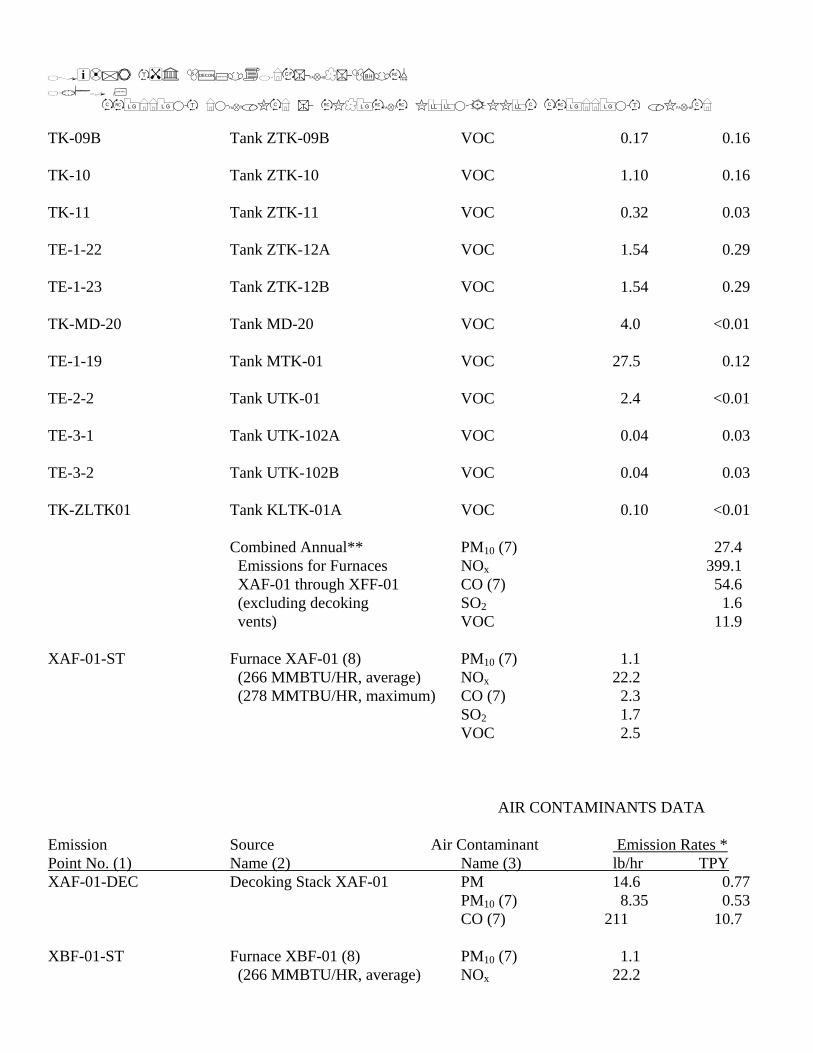
Permit No. 3452/PSD-TX-302M1 Page 6 EMISSION SOURCES - MAXIMUM ALLOWABLE EMISSION RATES TK-09B Tank ZTK-09B VOC 0.17 0.16 TK-10 Tank ZTK-10 VOC 1.10 0.16 TK-11 Tank ZTK-11 VOC 0.32 0.03 TE-1-22 Tank ZTK-12A VOC 1.54 0.29 TE-1-23 Tank ZTK-12B VOC 1.54 0.29 TK-MD-20 Tank MD-20 VOC 4.0 <0.01 TE-1-19 Tank MTK-01 VOC 27.5 0.12 TE-2-2 Tank UTK-01 VOC 2.4 <0.01 TE-3-1 Tank UTK-102A VOC 0.04 0.03 TE-3-2 Tank UTK-102B VOC 0.04 0.03 TK-ZLTK01 Tank KLTK-01A VOC 0.10 <0.01
Combined Annual** PM10 (7) 27.4 Emissions for Furnaces NOx 399.1 XAF-01 through XFF-01 CO (7) 54.6 (excluding decoking SO2 1.6 vents) VOC 11.9
XAF-01-ST Furnace XAF-01 (8) PM10 (7) 1.1
(266 MMBTU/HR, average) NOx 22.2 (278 MMTBU/HR, maximum) CO (7) 2.3
SO2 1.7 VOC 2.5
AIR CONTAMINANTS DATA Emission Source Air Contaminant Emission Rates * Point No. (1) Name (2) Name (3) lb/hr TPY XAF-01-DEC Decoking Stack XAF-01 PM 14.6 0.77
PM10 (7) 8.35 0.53 CO (7) 211 10.7
XBF-01-ST Furnace XBF-01 (8) PM10 (7) 1.1
(266 MMBTU/HR, average) NOx 22.2

Permit No. 3452/PSD-TX-302M1 Page 7 EMISSION SOURCES - MAXIMUM ALLOWABLE EMISSION RATES
(278 MMTBU/HR, maximum) CO (7) 2.3 SO2 1.7 VOC 2.5
XBF-01-DEC Decoking Stack XBF-01 PM 14.6 0.77
PM10 (7) 8.35 0.53 CO (7) 211 10.7
XCF-01-ST Furnace XCF-01 (8) PM10 (7) 1.1
(266 MMBTU/HR, average) NOx 22.2 (278 MMTBU/HR, maximum) CO (7) 2.3
SO2 1.7 VOC 2.5
XCF-01-DEC Decoking Stack XCF-01 PM 14.6 0.77
PM10 (7) 8.35 0.53 CO (7) 211 10.7
XDF-01-ST Furnace XDF-01 (8) PM10 (7) 1.1
(266 MMBTU/HR, average) NOx 22.2 (278 MMTBU/HR, maximum) CO (7) 2.3
SO2 1.7 VOC 2.5
XDF-01-DEC Decoking Stack XDF-01 PM 14.6 0.77
PM10 (7) 8.35 0.53 CO (7) 211 10.7
XEF-01-ST Furnace XEF-01 (8) PM10 (7) 1.1
(266 MMBTU/HR, average) NOx 22.2 (278 MMTBU/HR, maximum) CO (7) 2.3
SO2 1.7 VOC 2.5
AIR CONTAMINANTS DATA
Emission Source Air Contaminant Emission Rates * Point No. (1) Name (2) Name (3) lb/hr TPY XEF-01-DEC Decoking Stack XEF-01 PM 14.6 0.77
PM10 (7) 8.35 0.53 CO (7) 211 10.7
XFF-01-ST Furnace XFF-01 (8) PM10 (7) 1.1
(266 MMBTU/HR, average) NOx 22.2 (278 MMTBU/HR, maximum) CO (7) 2.3
SO2 1.7

Permit No. 3452/PSD-TX-302M1 Page 8 EMISSION SOURCES - MAXIMUM ALLOWABLE EMISSION RATES
VOC 2.5 XFF-01-DEC Decoking Stack XFF-01 PM 14.6 0.77
PM10 (7) 8.35 0.53 CO (7) 211 10.7
XKL01 Filming Amine Tank VOC 4.15 0.01 XLL03 Lube Oil Tank 1 VOC 0.15 <0.01 XVL02 Lube Oil Tank 2 VOC 0.12 <0.01 XZL03 Neutralizing Amine Tank VOC 4.15 0.01 XZL16 Emergency Generator PM 1.3 0.10
(156 hours per year) NOx 18.5 1.44 CO 4.0 0.31 SO2 1.2 0.10 VOC 1.5 0.12
XZL45 Aqueous Ammonia Tank NH3 2.70 0.05 XZLTK16 Diesel Fuel Tank VOC 0.19 <0.01 XZTK04 Oily Sludge Tank VOC 0.13 0.03 XZTK05 WW Equalization Tank VOC 0.66 0.57 XZTK06 Spent Caustic Tank VOC 0.03 0.07
NaOH <0.01 <0.01 XZTK07 Pyrolysis Fuel Oil Tank VOC <0.01 0.01
AIR CONTAMINANTS DATA Emission Source Air Contaminant Emission Rates * Point No. (1) Name (2) Name (3) lb/hr TPY XZTK08 Fresh Caustic Tank NaOH <0.01 <0.01 XZTK11 Wash Oil Tank VOC 0.08 0.01 XZTK13 Sulfuric Acid Tank H2SO4 0.05 0.01 (1) Emission point identification - either specific equipment designation or emission point number from plot plan. (2) Specific point source name. For fugitive sources use area name or fugitive source name. (3) PM - total suspended particulate

Permit No. 3452/PSD-TX-302M1 Page 9 EMISSION SOURCES - MAXIMUM ALLOWABLE EMISSION RATES
PM10 - particulate matter less than 10 microns*** NOx - total oxides of nitrogen CO - carbon monoxide SO2 - sulfur dioxide VOC - volatile organic compounds as defined in General Rule 101.1 NH3 - ammonia NaOH - sodium hydroxide H2SO4 - sulfuric acid (4) Fugitive emissions are an estimate only and should not be considered as a maximum allowable emission rate. (5) The burning rate of Furnace AF-01 and Furnaces CF-01 through GF-01 shall not exceed 350 MMBTU/HR
each averaged over an operating day. The burning rate of Furnace HF-01 shall not exceed 238 MMBTU/HR averaged over an operating day. Interim Operation - The combined burning rate of Furnace AF-01 and Furnaces CF-01 through HF-01 shall not exceed 1,731 MMBTU/HR on a rolling 12-month basis or 1,756 MMBTU/HR averaged over an operating day. Final Limits - These operational limits become effective upon commencement of operation of one or more of the following Furnaces: XAF-01, XBF-01, XCF-01, XDF-01, XEF-01, XFF-01: the combined burning rate of Furnace AF-01 and Furnaces CF-01 through HF-01 shall not exceed 1,443 MMBTU/HR on a rolling 12-month basis or 1,756 MMBTU/HR averaged over an operating day.
(6) These emission rates become effective upon commencement of operation of one or more of the following Furnaces: XAF-01, XBF-01, XCF-01, XDF-01, XEF-01, XFF-01.
(7) These are the PSD-TX-302M1 emissions. (8) The combined burning rate of Furnaces XAF-01 through XFF-01 shall not exceed 1,519 MMBTU/HR on a
rolling 12-month basis.

Permit No. 3452/PSD-TX-302M1 Page 10 EMISSION SOURCES - MAXIMUM ALLOWABLE EMISSION RATES (9) These are the emissions related to PSD-TX-302. * Emission rates are based on and the facilities are limited by the following maximum operating schedule: Hrs/year 8,760 ** 12-month rolling average. *** PM10 is taken as equal to PM for cracking furnace combustion vent emissions. Dated

SPECIAL CONDITIONS Permit No. 3452/PSD-TX-302M1 EMISSION STANDARDS 1. The total of all air contaminants from any of the sources shall not exceed the values stated on
the attached table entitled "Emission Sources - Maximum Allowable Emission Rates" and as provided in Special Conditions No. 2 and 3 below.
2. Visible emissions resulting from the decoking of the cracking furnaces shall not exceed an
opacity of 10 percent averaged over a six-minute period, as determined by a trained observer. 3. Total oxides of nitrogen (NOx) emissions from each of the following furnaces shall be limited
to 0.120 pound of NOx per MMBTU as a hourly average and 0.092 pound of NOx per MMBTU as a rolling 12-month average: IF-01 and JF-01.
The NOx emissions from Furnace BF-01 shall be limited to 0.100 pound of NOx per MMBTU
as a hourly average and 0.080 pound of NOx per MMBTU as a rolling 12-month average. The NOx emissions from each of the following furnaces shall be limited to 0.080 pound of NOx
per MMBTU as a hourly average and 0.070 pound of NOx per MMBTU as a rolling 12-month average: OF-01 and QF-01.
The NOx emissions from each of the following furnaces shall be limited to 0.080 pound of NOx
per MMBTU as a hourly average and 0.060 pound of NOx per MMBTU as a rolling 12-month average: XAF-01, XBF-01, XCF-01, XDF-01, XEF-01, and XFF-01.
Upon commencement of operation of one or more of the following Furnaces, XAF-01, XBF-01, XCF-01, XDF-01, XEF-01, or XFF-01, NOx emissions from each of the following furnaces shall be limited to 0.177 pound of NOx per MMBTU as a hourly average and 0.140 pound of NOx per MMBTU as a rolling 12-month average: AF-01, CF-01, DF-01, EF-01, FF-01, GF-01, and HF-01.
Special Condition No. 3 NOx limits (pounds of NOx per MMBTU) are not applicable when the cracking furnace is in its decoking cycle; however, the NOx mass emission rates specified in the maximum allowable emission rates table (MAERT) shall not be exceeded when the cracking furnace is in its decoking cycle.
FEDERAL APPLICABILITY 4. These facilities shall comply with all applicable requirements of U.S. Environmental Protection
Agency (EPA) Regulations on Standards of Performance for New Stationary Sources promulgated for Storage Vessels for Petroleum Liquids, for Volatile Organic Liquid Storage Vessels, for Equipment Leaks of Volatile Organic Compounds (VOC) in the Synthetic Organic Chemicals Manufacturing Industry (SOCMI), for VOC Emissions from SOCMI Distillation Operations, and for VOC Emissions from SOCMI Reactor Processes in Title 40 Code of Federal Regulations Part 60 (40 CFR 60), Subparts A, K, Kb, VV, NNN, and RRR. These
SPECIAL CONDITIONS Permit No. 3452/PSD-TX-302M1 Page 2
facilities shall also comply with the compliance schedule for all applicable requirements of New Source Performance Standards (NSPS), Subpart YYY (Control of VOC from SOCMI Wastewater), upon promulgation.
5. These facilities shall comply with all applicable requirements of EPA Regulations on National
Emission Standards for Hazardous Air Pollutants (NESHAPS) promulgated for Equipment Leaks of Benzene, for Equipment Leaks, and for Benzene Waste Operations in 40 CFR 61, Subparts A, J, V, and FF.
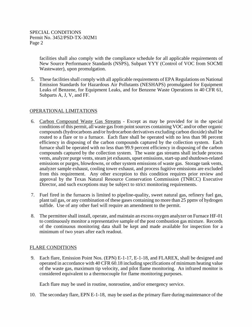
OPERATIONAL LIMITATIONS 6. Carbon Compound Waste Gas Streams - Except as may be provided for in the special
conditions of this permit, all waste gas from point sources containing VOC and/or other organic compounds (hydrocarbons and/or hydrocarbon derivatives excluding carbon dioxide) shall be routed to a flare or to a furnace. Each flare shall be operated with no less than 98 percent efficiency in disposing of the carbon compounds captured by the collection system. Each furnace shall be operated with no less than 99.9 percent efficiency in disposing of the carbon compounds captured by the collection system. The waste gas streams shall include process vents, analyzer purge vents, steam jet exhausts, upset emissions, start-up and shutdown-related emissions or purges, blowdowns, or other system emissions of waste gas. Storage tank vents, analyzer sample exhaust, cooling tower exhaust, and process fugitive emissions are excluded from this requirement. Any other exception to this condition requires prior review and approval by the Texas Natural Resource Conservation Commission (TNRCC) Executive Director, and such exceptions may be subject to strict monitoring requirements.
7. Fuel fired in the furnaces is limited to pipeline-quality, sweet natural gas, refinery fuel gas,
plant tail gas, or any combination of these gases containing no more than 25 ppmv of hydrogen sulfide. Use of any other fuel will require an amendment to the permit.
8. The permittee shall install, operate, and maintain an excess oxygen analyzer on Furnace HF-01
to continuously monitor a representative sample of the post combustion gas mixture. Records of the continuous monitoring data shall be kept and made available for inspection for a minimum of two years after each readout.
FLARE CONDITIONS 9. Each flare, Emission Point Nos. (EPN) E-1-17, E-1-18, and FLAREX, shall be designed and
operated in accordance with 40 CFR 60.18 including specifications of minimum heating value of the waste gas, maximum tip velocity, and pilot flame monitoring. An infrared monitor is considered equivalent to a thermocouple for flame monitoring purposes.
Each flare may be used in routine, nonroutine, and/or emergency service.
10. The secondary flare, EPN E-1-18, may be used as the primary flare during maintenance of the

SPECIAL CONDITIONS Permit No. 3452/PSD-TX-302M1 Page 3
primary flare, EPN E-1-17, or may be used in conjunction with or in lieu of the primary flare in normal service.
11. The following requirements apply to the operation of the primary flare (or to the secondary
flare when it is operated in place of the primary flare):
The permittee shall measure rates of waste gas flow to the flares downstream of the flare knockout drum. The gas flow rate shall be accurately measured and accounted for so that a daily and a monthly total flow rate can be determined. Measurement devices shall meet or exceed the most recently published Standards of the American Gas Association for accuracy and precision.
The permittee shall obtain and analyze a sample of flare waste gas downstream of the flare knockout drum when the flare is in service. Samples must be taken and analyzed for at least 95 percent of the operating days. Samples may be grab samples. Each sample shall be analyzed by the extended gas chromatograph method to provide a complete composition of all hydrocarbons and other compounds (including carbon dioxide, carbon monoxide (CO), hydrogen, and nitrogen) contained in the gas streams at more than 1.0 percent by weight. Individual C4s and heavier hydrocarbons contained at less than 1.0 percent by weight may be grouped in this analysis.
The permittee shall calculate the monthly average VOC emissions for each month not later than the 30th day following the month for which the average is being calculated.
The permittee shall apply TNRCC flare emission factors when calculating flare air contaminant emission rates.
Records of VOC emissions (pounds per month) for each month and on a rolling 12-month average shall be maintained at the plant site and cover at least the trailing two-year period. They shall be immediately available upon request to TNRCC personnel or any local air pollution control program having jurisdiction.
LEAK DETECTION AND REPAIR PROGRAM 12. Piping, Valves, Flanges, Pumps, and Compressors in VOC Service - Intensive Directed
Maintenance
Except as may be provided for in the special conditions of this permit, the following requirements apply to the above-referenced equipment.
A. These conditions shall not apply (1) where the VOC have an aggregate partial pressure or
vapor pressure of less than 0.044 psia at 68°F or (2) where the operating pressure is at least 5 kilopascals (0.725 psi) below ambient pressure. Equipment excluded from this condition shall be identified in a list to be made available upon request.
B. Construction of new and reworked piping, valves, and pump and compressor systems shall conform to applicable ANSI, API, ASME, or equivalent codes.

SPECIAL CONDITIONS Permit No. 3452/PSD-TX-302M1 Page 4
C. New and reworked underground process pipelines shall contain no buried valves such that fugitive emission monitoring is rendered impractical.
D. To the extent that good engineering practice will permit, new and reworked valves and
piping connections shall be so located to be reasonably accessible for leak-checking during plant operation. Non-accessible valves, as defined by TNRCC Regulation V, shall be identified in a list to be made available upon request.
E. New and reworked piping connections shall be welded or flanged (screwed connections are
permissible only on piping smaller than two-inch diameter). No later than the next scheduled quarterly monitoring after initial installation or replacement, all new or reworked connections shall be gas-tested or hydraulically-tested at no less than normal operating pressure and adjustments made as necessary to obtain leak-free performance. Flanges shall be inspected by visual, audible, and/or olfactory means at least weekly by operating personnel walk-through.
Each open-ended valve or line shall be equipped with a cap, blind flange, plug, or a second valve. Except during sampling, the second valve shall be closed.
F. Accessible valves shall be monitored by leak-checking for fugitive emissions at least
quarterly using an approved gas analyzer with a directed maintenance program. Sealless/leakless valves (including, but not limited to, welded bonnet bellows and diaphragm valves) and relief valves equipped with a rupture disc upstream or venting to a control device are not required to be monitored. For valves equipped with rupture discs, a pressure gauge shall be installed between the relief valve and rupture disc to monitor disc integrity. All leaking discs shall be replaced at the earliest opportunity but no later than the next process shutdown.
An approved gas analyzer shall conform to requirements listed in 40 CFR 60.485(a)-(b).
A directed maintenance program shall consist of the repair and maintenance of components assisted simultaneously by the use of an approved gas analyzer such that a minimum concentration of leaking VOC is obtained for each component being maintained. Replaced components shall be re-monitored within 15 days of being placed back into VOC service.
G. Except as may be provided for in the special conditions of this permit, all pump and
compressor seals shall be monitored with an approved gas analyzer at least quarterly or be equipped with a shaft sealing system that prevents or detects emissions of VOC from the seal. Seal systems designed and operated to prevent emissions or seals equipped with an automatic seal failure detection and alarm system need not be monitored. These seal systems may include (but are not limited to) dual pump seals with barrier fluid at higher pressure than process pressure, seals degassing to vent control systems kept in good working order, or seals equipped with an automatic seal failure detection and alarm system. Submerged pumps or sealless pumps (including, but not limited to, diaphragm, canned, or magnetic driven pumps) may be used to satisfy the requirements of this

SPECIAL CONDITIONS Permit No. 3452/PSD-TX-302M1 Page 5
condition and need not be monitored. H. Damaged or leaking valves or flanges found to be emitting VOC in excess of 500 ppmv or
found by visual inspection to be leaking (e.g., dripping liquids) shall be tagged and replaced or repaired. Damaged or leaking pump and compressor seals found to be emitting VOC in excess of 2,000 ppmv or found by visual inspection to be leaking (e.g., dripping liquids) shall be tagged and replaced or repaired.
I. Every reasonable effort shall be made to repair a leaking component, as specified in this
paragraph, within 15 days after the leak is found. If the repair of a component would require a unit shutdown, the repair may be delayed until the next scheduled shutdown. All leaking components which cannot be repaired until a scheduled shutdown shall be identified for such repair by tagging. The TNRCC Executive Director, at his discretion, may require early unit shutdown or other appropriate action based on the number and severity of tagged leaks awaiting shutdown.
J. The results of the required fugitive monitoring and maintenance program shall be made
available to the TNRCC Executive Director or his designated representative upon request. Records shall indicate appropriate dates, test methods, instrument readings, repair results, and corrective actions taken for all components. Records of flange inspections are not required unless a leak is detected.
K. Alternative monitoring frequency schedules of TNRCC Regulation V and Hazardous
Organic NESHAPS may be used in lieu of Items F through G of this condition. Compliance with the requirements of this condition does not assure compliance with requirements of TNRCC Regulation V, an applicable NSPS, or an applicable NESHAPS and does not constitute approval of alternative standards for these regulations.
13. A. Special Condition No. 13A becomes effective upon commencement of operation of one or
more of the following Furnaces: XAF-01, XBF-01, XCF-01, XDF-01, XEF-01, or XFF-01:
Flange Monitoring - Instead of the sensory-based program for flange monitoring specified in Special Condition No. 12E above, the permittee shall monitor flanges by leak-checking for fugitive emissions at least quarterly using an approved gas analyzer with a directed maintenance program. Special Condition No. 12K also applies to flange monitoring.
B. Pump and Compressor Seal Monitoring - Instead of the leak definition of 2,000 ppmv
specified for instrument monitoring of pump and compressor seals in Special Condition No. 12H above, the permittee shall use a leak definition of 500 ppmv for pump and compressor seal instrument monitoring.
14. Cooling Tower Monitoring - The VOC associated with cooling tower water shall be monitored
at least monthly with an approved air stripping system, on-line gas chromatograph, or equivalent for the purpose of detecting leaks of VOC into the cooling water. When leaks are detected, the appropriate equipment shall be maintained so as to minimize fugitive VOC emissions from the cooling tower. Faulty equipment shall be repaired at the earliest

SPECIAL CONDITIONS Permit No. 3452/PSD-TX-302M1 Page 6
opportunity, but no later than the next scheduled shutdown of the process unit in which the leak occurs. The results of the monitoring and maintenance efforts shall be recorded, and such records shall be maintained at the plant site and cover at least the two-year trailing period. The records shall be made available upon request to TNRCC personnel or any local air pollution control program having jurisdiction.
STORAGE OF VOC 15. A. These conditions shall not apply (1) where the VOC has an aggregate partial pressure of
less than 0.5 psia at the maximum expected operating temperature or (2) to storage tanks smaller than 25,000 gallons.
B. An internal floating roof or equivalent control shall be installed on all tanks.
C. For any tank equipped with a floating roof, the integrity of the floating roof seals shall be
verified annually and records maintained to describe dates, seal integrity, and corrective actions taken.
D. The floating roof design shall incorporate sufficient flotation to conform to the
requirements of API Code 650, Appendix C, or an equivalent degree of flotation, except that an internal floating cover need not be designed to meet rainfall support requirements.
E. Uninsulated tank exterior surfaces exposed to the sun shall be white.
F. For purposes of assuring compliance with VOC emission limitations, the holder of this
permit shall maintain a quarterly emissions record which describes calculated emissions of VOC from all storage tanks. The record shall include tank identification number, control method used, tank or vessel capacity, name of material stored, VOC molecular weight, VOC monthly average temperature for each month of the previous calendar quarter, VOC vapor pressure at the monthly average material temperature for each month of the previous calendar quarter, VOC throughput for each month of the previous calendar quarter and year-to-date in gallons, and total tons of emissions including control for each month of the previous calendar quarter and year-to-date. Where a tank is operated as a flow-through vessel, the required throughput record may be based on tank level changes during the reporting period. Where tanks are operated at ambient conditions, ambient temperature records may be used to satisfy the tank material temperature record retention requirements. This record shall be updated during the first month following each calendar quarter and shall be maintained at the plant site for at least two years and be made available to representatives of the TNRCC upon request.
G. The VOC emissions for storage tanks shall be calculated using: (a) the edition of AP-42, "Compilation of Air Pollutant Emission Factors," upon which the emission rates contained in the attached MAERT are based and (b) the TNRCC memo dated March 5, 1992 entitled "Annual and Short Term Emissions from Storage Tanks."
H. Controlled and uncontrolled emissions of VOC shall be calculated for storage tanks using

SPECIAL CONDITIONS Permit No. 3452/PSD-TX-302M1 Page 7
the following meteorological data as monthly average values:
Monthly Average Daily temperature change, °F 21.8
Wind speed, mph 7.6 Station pressure, psia 14.7
INITIAL DETERMINATION OF COMPLIANCE 16. The holder of this permit shall perform combustion stack sampling and other testing as required
to establish the actual pattern and quantities of air contaminants being emitted into the atmosphere from Furnaces XAF-01 through XFF-01. At least three of these furnaces shall be sampled.
The holder of this permit shall also perform combustion stack sampling and other testing as required to establish the actual pattern and quantities of air contaminants being emitted into the atmosphere from Furnace BF-01 following repair of that furnace.
The holder of this permit shall also perform combustion stack sampling and other testing as required to establish the actual pattern and quantities of air contaminants being emitted into the atmosphere from Furnaces AF-01, CF-01, DF-01, EF-01, FF-01, GF-01, and HF-01 after steam injection operation has commenced. At least three of these furnaces shall be sampled.
The holder of this permit is responsible for providing sampling and testing facilities and conducting the sampling and testing operations at his expense.
A. The appropriate TNRCC regional office in the region where the source is located shall be
contacted as soon as testing is scheduled but not less than 45 days prior to sampling to schedule a pretest meeting. The notice shall include:
(1) Date for pretest meeting. (2) Date sampling will occur. (3) Name of firm conducting sampling. (4) Type of sampling equipment to be used. (5) Method or procedure to be used in sampling.
SPECIAL CONDITIONS Permit No. 3452/PSD-TX-302M1 Page 8
The purpose of the pretest meeting is to review the necessary sampling and testing procedures, to provide the proper data forms for recording pertinent data, and to review the format procedures for submitting the test reports.
A written proposed description of any deviation from sampling procedures specified in permit conditions or TNRCC or EPA sampling procedures shall be made available to the TNRCC prior to the pretest meeting. The TNRCC Regional Manager or the Manager of the Engineering Services Section shall approve or disapprove of any deviation from specified sampling procedures.
Requests to waive testing for any pollutant specified in B of this condition shall be submitted to the TNRCC Austin New Source Review Division. Test waivers and alternate/equivalent procedure proposals for NSPS testing which must have EPA approval shall be submitted to the TNRCC Austin Air Quality Enforcement Division, Engineering Services Section.
B. Air contaminants to be tested for include (but are not limited to) NOx and CO emitted from
the combustion stack.
C. Sampling shall occur within 60 days after initial start-up of the facilities and at such other times as may be required by the Executive Director of the TNRCC. Requests for additional time to perform sampling shall be submitted to the appropriate TNRCC regional office. Additional time to comply with the applicable requirements of 40 CFR 60 and 40 CFR 61 requires EPA approval, and requests shall be submitted to the TNRCC Austin Engineering Services Section.
D. The furnace being tested shall operate at maximum firing rates during stack emission
testing. Primary operating parameters that enable determination of firing rate shall be monitored and recorded during the stack test. These parameters are to be determined at the pretest meeting. If the furnace is unable to operate at maximum rates during testing, then future firing rates may be limited to the rates established during testing. Additional stack testing may be required when higher firing rates are achieved.
E. Copies of the final sampling report shall be forwarded to the TNRCC within 30 days after
sampling is completed. Sampling reports shall comply with the attached provisions of Chapter 14 of the TNRCC Sampling Procedures Manual. The reports shall be distributed as follows:
One copy to the TNRCC Houston Regional Office. One copy to the appropriate local air pollution control program. One copy to the TNRCC Austin Air Quality Enforcement Division, Engineering Services Section. One copy to the EPA New Source Review Section, Dallas.

SPECIAL CONDITIONS Permit No. 3452/PSD-TX-302M1 Page 9
F. Stack sampling of Furnaces AF-01, CF-01, DF-01, EF-01, FF-01, GF-01, and HF-01, after steam injection operation has commenced, shall be repeated every five years after the initial testing in conformity with Paragraphs A, B, D, and E of this condition. At least three of these furnaces shall be sampled.
Stack sampling of Furnace BF-01, after repair of that furnace, shall be repeated every five years after the initial testing in conformity with Paragraphs A, B, D, and E of this condition.
CONTINUOUS DETERMINATION OF COMPLIANCE 17. The holder of this permit shall install, calibrate, and maintain a continuous emission monitoring
system (CEMS) to measure and record the in-stack concentration of NOx from the main stacks of Furnaces IF-01, JF-01, OF-01, QF-01, XAF-01, XBF-01, XCF-01, XDF-01, XEF-01, and XFF-01.
A. Each CEMS shall meet the design and performance specifications, pass the field tests, and
meet the installation requirements and the data analysis and reporting requirements specified in the applicable Performance Specifications No. 1 through 6, 40 CFR 60, Appendix B. If there are no applicable performance specifications in 40 CFR 60, Appendix B, contact the TNRCC in Austin for requirements to be met.
B. Each system shall be zeroed and spanned daily and corrective action taken when the
24-hour span drift exceeds two times the amounts specified in 40 CFR 60, Appendix B, or as specified by the TNRCC if not specified in Appendix B. Zero and span is not required on weekends and plant holidays if instrument technicians are not normally scheduled on those days, unless the monitor is required by a subpart of NSPS or NESHAPS, in which case zero and span shall be done daily without exception.
Each monitor shall be quality-assured at least quarterly in accordance with 40 CFR 60, Appendix F, Procedure 1, Section 5.1.2. For non-NSPS sources, an equivalent method approved by the TNRCC may be used.
All cylinder gas audit exceedances of +15 percent accuracy and any CEMS downtime shall be reported to the appropriate TNRCC Regional Manager, and necessary corrective action shall be taken. Supplemental stack concentration measurements may be required at the discretion of the appropriate TNRCC Regional Manager.
C. The monitoring data shall be reduced to hourly average concentrations at least once every
day, using a minimum of four equally-spaced data points from each one-hour period. Flow rates used to convert ppmv(d) to mass emission rates in lb/hr and lb/MMBTU may be obtained from calculations based on the firing rate of each furnace, the stack temperature of each furnace, and the percent oxygen in the exhaust stack of each furnace. The individual average concentrations shall be reduced to units of the permit allowable emission rate in pounds per hour of NOx at least once every day. The calculated pounds

SPECIAL CONDITIONS Permit No. 3452/PSD-TX-302M1 Page 10
per hour of NOx for each operating hour shall be recorded. The calculated lb/MMBTU of NOx for each operating day shall be recorded.
D. All hourly average and daily average monitoring data and quality-assurance data shall be
maintained by the permittee for a period of at least two years and shall be made available upon request to representatives of the TNRCC. The data from the CEMS may, at the discretion of the TNRCC, be used to determine compliance with the conditions of this permit.
E. For NSPS sources subject to Appendix F, the appropriate TNRCC regional office shall be
notified at least 30 days prior to each annual relative accuracy testing audit (RATA) in order to provide them the opportunity to observe the testing.
18. In lieu of installation and operation of a CEMS to measure and record the in-stack
concentration of NOx from the main stacks of Furnaces XAF-01, XBF-01, XCF-01, XDF-01, XEF-01, and XFF-01 as provided in Special Condition No. 17 above, the permittee may use predictive emissions monitoring systems (PEMS) for demonstrating continuous compliance if it can be demonstrated to have the same or better accuracy, precision, reliability, accessibility, and timeliness as that provided by a hardware CEMS.
A generic PEMS, developed for a similarly designed cracking furnace, may be installed at the time of commencement of operation of a furnace and used, instead of a CEMS or permanent PEMS, to measure and record the in-stack concentration of NOx for a period of time not to exceed six months. The PEMS may be retrained using data collected during the initial demonstration of compliance and subsequently collected test data.
All permanent PEMS must be approved by the Executive Director of the TNRCC. The permittee must petition the TNRCC Executive Director for approval to use permanent PEMS. The petition must include results of tests conducted to demonstrate equivalent accuracy and precision of PEMS to that of a hardware CEMS.
A. If a PEMS is used to demonstrate continuous compliance, the holder of this permit shall
install, calibrate, maintain, and operate flow meters to monitor and record flows of fuels being fired in the furnace(s). All other parameters necessary for PEMS operation within the acceptable performance requirements must also be monitored and recorded. In addition:
(1) The PEMS must be based on measured parameters including (but not limited to) fuel
flow, steam injection rate or pressure, and excess combustion air quantity.
(2) The PEMS output as pounds of NOx per hour will be averaged for each calendar hour, and as pounds of NOx per MMBTU fired will be averaged for operating day. These results shall be recorded.
(3) The PEMS shall meet the requirements specified in TNRCC Regulation VII, Rule
117.213(c) as applicable to the monitoring of NOx emissions. For the purposes of

SPECIAL CONDITIONS Permit No. 3452/PSD-TX-302M1 Page 11
compliance with the requirements for quarterly RATA specified in Rule 117.213(c)(3)(B)(I), and for the purposes of this permit only, if operating time during a calendar quarter is less than 60 days, the owner or operator may delay the RATA until the next calendar quarter; however, the RATA must be performed within 90 facility (furnace) operating days after the previous RATA was completed. A quarterly RATA may be omitted if the facility is inoperative for 90 or more successive days.
(4) The PEMS downtime summaries shall be submitted to the appropriate TNRCC
Regional Manager once each calendar quarter. If no downtime periods occur, this shall be so stated in the quarterly summary. Necessary corrective action shall be taken for each PEMS downtime occurrence.
(5) Within 60 days after the PEMS is developed and installed on any furnace, a RATA
shall be performed. Results of testing shall be submitted to the appropriate TNRCC regional office within 30 days after completion of the RATA. A results summary of all criteria testing performed pursuant to TNRCC Regulation VII, Rule 117.213(c), shall be submitted within 60 days after completion of such tests.
(6) Following the three successive RATA referenced in paragraph (3) above, a RATA
must be performed every six months pursuant to 40 CFR 60, Appendix B, Performance Specification 2, Subsection 4.3 (pertaining to NOx). The RATA may be performed every 12 months if the relative accuracy during the previous audit for the NOx monitor is less than or equal to 7.5 percent. Any RATA exceeding 20 percent or statistical test exceeding the applicable standard shall be reported to the appropriate TNRCC Regional Manager. A single RATA may be performed when any required quarterly and semi-annual or annual RATA occur concurrently.
B. All monitoring data and all quality-assurance data required by Special Condition No. 19
shall be maintained at the plant site for a period of at least two years and shall be made available upon request to representatives of the TNRCC. The data from the CEMS or PEMS may, at the discretion of the TNRCC, be used to determine compliance with the conditions of this permit.
C. For NSPS sources subject to Appendix F, or for the demonstration of PEMS performance,
the appropriate TNRCC regional office shall be notified at least 30 days prior to each RATA in order to provide them the opportunity to observe the testing.
D. The holder of this permit shall perform automatic sensor validation at least daily on any
PEMS installed under the authority of this permit. The permittee shall develop and implement plans that will ensure proper functioning of the monitoring systems, ensure proper accuracy and calibration of all operational parameters that affect emissions and serve as input to the PEMS, and ensure continuous operation within the certified operating range.
E. A PEMS is required to provide valid emission predictions at least 95 percent of the time that the furnace being monitored is operated.

SPECIAL CONDITIONS Permit No. 3452/PSD-TX-302M1 Page 12 FACILITY THROUGHPUT 19. A. Records of ethylene production shall be maintained and updated each month for the rolling
12-month period. These records shall be maintained at the plant site and cover at least the trailing two-year period. They shall be immediately available upon request to TNRCC personnel or any local air pollution control program having jurisdiction.
Ethylene production at this facility is limited to 2.7 billion pounds per year on a rolling 12-month basis. Upon commencement of operation of Furnaces XAF-01 through XFF-01, ethylene production at this facility is limited to 4.3 billion pounds per year on a rolling 12-month basis.
B. The feed rate for the Crude Isoprene Recovery Unit shall not exceed 110,000 pounds per
hour of steam cracked naphtha (SCN) imports. Records of the maximum feed rate (pounds per hour) of SCN imports to the Crude Isoprene Recovery Unit for each operating day shall be maintained at the plant site and cover at least the trailing two-year period. They shall be immediately available upon request to TNRCC personnel or any local air pollution control program having jurisdiction.
CONTEMPORANEOUS REDUCTIONS 20. Construction of Furnaces I and J approved by issuance of Permit No. 18967 is conditioned on
the permanent NOx reductions obtained by shutdown of Furnaces F-801 and F-802. 21. Implementation of the Base Plant Phase II Debottlenecking Project including construction of
Furnaces O and Q approved by the March 5, 1993 amendment of Permit No. 3452 is conditioned on the permanent NOx reductions obtained by those actions specified in Attachment A entitled "Summary of Permanent Reductions."
22. The increase in Crude Isoprene Recovery Unit capacity authorized by the October 7, 1993
amendment of Permit No. 3452C is conditioned on the permanent VOC reductions obtained by implementation of a 28MID program or equivalent at the Propylene Recovery Unit (Permit No. 19068), at the Base Plant (Permit No. 3452), and at the Crude Isoprene Recovery Unit (Permit No. 3452C). (Special Condition No. 12 is modified by Special Condition No. 13B to create a program equivalent to 28MID.)
23. Construction of the following Furnaces, XAF-01, XBF-01, XCF-01, XDF-01, XEF-01, and
XFF-01, is conditioned on the completion of all NOx and VOC emission reduction projects represented in the permit amendment application (Record No. 33771) and identified in Table 2N, "Non-Attainment NOx", Table 2N, "NOx PSD", and Table 2N, "VOC Netting." These reductions of emissions shall occur not later than the commencement of operation of these permitted facilities.
Not later than 30 days after commencement of operation of any one of the following Furnaces,

SPECIAL CONDITIONS Permit No. 3452/PSD-TX-302M1 Page 13
XAF-01, XBF-01, XCF-01, XDF-01, XEF-01, or XFF-01, the permittee shall calculate the actual NOx emissions from existing Furnaces AF-01, CF-01, DF-01, EF-01, FF-01, GF-01, and HF-01 in tons per year for the two-year period ending with commencement of operation of any one of the following Furnaces, XAF-01, XBF-01, XCF-01, XDF-01, XEF-01, or XFF-01 and shall submit the calculations and an updated Table 1N to the TNRCC Austin Air Quality, New Source Review Division. This information shall be reviewed and the permit shall be revised to assure that a reduction of at least 118.2 tons per year of NOx emissions, calculated by subtracting the new allowable for the existing furnaces in steam injection operation from the trailing two-year actual average, will be obtained from Furnaces AF-01, CF-01, DF-01, EF-01, FF-01, GF-01, and HF-01.
Commencement of operation of a furnace is defined as the moment when hydrocarbons are introduced to the process side of the furnace tubes for the purpose of producing olefins.
24. The holder of this permit shall maintain records of the emission reductions related to Special
Condition Nos. 20, 21, 22, and 23 above and shall provide access and/or copies to TNRCC personnel upon request or any local air pollution control program having jurisdiction. Pursuant to 40 CFR 52.21(b)(9) or 40 CFR 51.165(a)(1)(xvi), construction of these facilities must commence no later than five years after the reductions are actually accomplished, otherwise, the reductions are no longer creditable and project approval is automatically void.
STEAM INJECTION 25. Upon commencement of operation of one or more of the following Furnaces, XAF-01,
XBF-01, XCF-01, XDF-01, XEF-01, or XFF-01, the holder of this permit shall control NOx emissions from existing Furnaces AF-01, CF-01, DF-01, EF-01, FF-01, GF-01, and HF-01 as required in Special Condition No. 3. Steam shall be injected at or above the rate necessary to maintain combustion air humidity at 0.0175 pound of water per pound of dry combustion air at each individual furnace not less than 95 percent of the operating hours of that furnace.
With regard to Furnaces AF-01, CF-01, DF-01, EF-01, FF-01, GF-01, and HF-01, the amount of steam injected during each operating hour shall be measured and recorded. Ambient humidity, as pounds of water per pound of dry air, must be measured or calculated and recorded for each operating hour. Monitoring data shall be reduced to units of pounds of water per pound of dry combustion air for each operating hour at least once per day for each individual furnace. The number of hours that combustion air humidity falls below 0.0175 pounds of water per pound of dry combustion air and the total number of operating hours shall also be recorded with regard to each individual furnace. The percentage of hours that comply with 0.0175 pound of water per pound of dry combustion air shall be calculated and recorded for each furnace on a rolling 12-month basis, updated at least once every month. These records, beginning with the effective date of this condition, shall be maintained at the plant site and cover at least the previous two-year period. They shall be made available upon request to TNRCC personnel or to any local air pollution control program having jurisdiction.

SPECIAL CONDITIONS Permit No. 3452/PSD-TX-302M1 Page 14 RECORDKEEPING 26. Records shall be kept on each cracking furnace of the average burning rate for each operating
day and the average burning rate on a rolling 12-month basis. These records shall be updated each month for the previous 12-calendar-month period. These records shall be maintained at the plant site and cover at least the trailing two-year period. They shall be made available upon request to TNRCC personnel or to any local air pollution control program having jurisdiction.
The burning rates of cracking furnaces shall be calculated using the higher heating value basis.
Dated

Attachment A Permit No. 3452/PSD-TX-302M1 Summary of Permanent Reductions Permit No. Facility Name EPN TPY 9489 (1) Furnace F-501 2 5.54 9489 (2) Furnace F-503 N/A 7.94 3871-3874 (3) Boilers A through D E-7-1 219 1419 (4) Furnace F311 FU1 21.81 1419 (4) Furnace F321 FU2 17.71 5259 (5) Furnace H9A H9ANRU 54.95 5259 (5) Furnace H9B H9BNRU 54.95 (1) The authorized burning rate is 47.625 MMBTU/HR. The authorized emission factor is 0.12 lbs
NOx/MMBTU. (2) Furnace F-503 has been permanently removed from service. (3) The authorized combined burning rate is 1,234 MMBTU/HR over a rolling 12-month period.
The authorized emission factors are 0.20 lb NOx/MMBTU (gaseous fuel) and 0.30 lb NOx/MMBTU (liquid fuel).
(4) The authorized burning rate is 120 MMBTU/HR for Furnace F311 and 134 MMBTU/HR for
Furnace F321. The authorized emission factor is 0.067 lb NOx/MMBTU. (5) The authorized burning rate for Furnaces H9A and H9B is 133 MMBTU/HR each. The
authorized emission factor is 0.067 lb NOx/MMBTU. Dated