Preliminary Design Review May 20, 2003 PMT HV Base Board Engineering Requirements Nobuyoshi Kitamura...
19
Preliminary Design Review May 20, 2003 PMT HV Base Board Engineering Requirements Nobuyoshi Kitamura SSEC / UW-Madison
-
Upload
junior-berry -
Category
Documents
-
view
215 -
download
0
Transcript of Preliminary Design Review May 20, 2003 PMT HV Base Board Engineering Requirements Nobuyoshi Kitamura...

Preliminary Design ReviewMay 20, 2003
PMT HV Base Board Engineering Requirements
Nobuyoshi KitamuraSSEC / UW-Madison

N. Kitamura SSEC / UW-Madison May 20, 2003
2/19
Outline
IceCube PMT HV Base Board ERD version 2.3 (March 7, 2003)http://www.ssec.wisc.edu/~kitamura/NK/PMT_Base/PMTHVBaseERD_ver2.3.pdf
1. Functionality overview
2. Design statusStatus of the dual-track approachKnown design / requirements issuesRequirements update
3. Document walk-through with summary tablesIs the requirement valid (justified)?How do you verify it?
TestAnalysisInspectionDemonstrationSimilarity
4. Discussion

N. Kitamura SSEC / UW-Madison May 20, 2003
3/19
ERD
PMT HV Base BoardFunctionality
Target DeviceHamamatsu
R7081-02
Host DeviceDOM Main Board
Operating Environment

N. Kitamura SSEC / UW-Madison May 20, 2003
4/19
PMT HV Base Board2 Functional Overview
PMT HV Base Board
PMTDigital Optical Module Main Board(DOMMB)
DigitalcontrolPower
PMTAnodesignal
Digital Interface Analog Interface
Highvoltage
Purpose of the PMT HV Base Board Page 6, Section 2, Paragraph 4
Fig 2.1

N. Kitamura SSEC / UW-Madison May 20, 2003
5/19
Dual-Track Design Approach
Active Base (All-in-one) approach
ERD assumes this as a default configuration
Passive Base approach
Section 3.1.1.1 allows an alternative configurationERD Supplement (ver 0.00c, Jan. 13, 2003) defines alternative requirementshttp://www.ssec.wisc.edu/~kitamura/NK/PMT_Base/PMTBaseERD%20suppl0.00c.pdf

N. Kitamura SSEC / UW-Madison May 20, 2003
6/19
Alternative Design-- “Passive Base” Approach
•Classical approach to operate PMT•Simpler (and modular) basic components•No cost advantage (unlike initially anticipated)
“Passive Base”
PMTDigital Optical Module Main Board(DOMMB)
DigitalcontrolPower
PMTAnodesignal
Digital Interface Analog Interface
Highvoltage
HV Generator
“Passive base support devices”(On Flasher Board)

N. Kitamura SSEC / UW-Madison May 20, 2003
7/19
Comparison of the Requirements Between the Two Approaches
Requirement ERD Section Active Base
Passive Base
Fixed 1st Dynode Voltage at 700V
3.1.4.1.A Yes No. Vdy1 scales with Vtotal
Cathode-Anode voltage adjustable over 1000-2000VDC
3.1.4.1.B Yes Yes
Dynode 2-Anode voltage ratio (Table 3.1)
3.1.3.2 Yes Yes. Plus a high Vdy1 fraction per Hamamatsu.
Split ground 3.2.2.1 Yes No. Insert ferrite bead between grounds.
Clean ground wire 3.2.2.1.E Yes No
Ribbon cable 3.2.5.2 Yes Yes. Connector on interface board.
Component placement 3.3.3 Yes Remove (c), (d), (e), (g)
N. Kitamura SSEC / UW-Madison May 20, 2003
8/19
PMT HV Base BoardAlternative Design
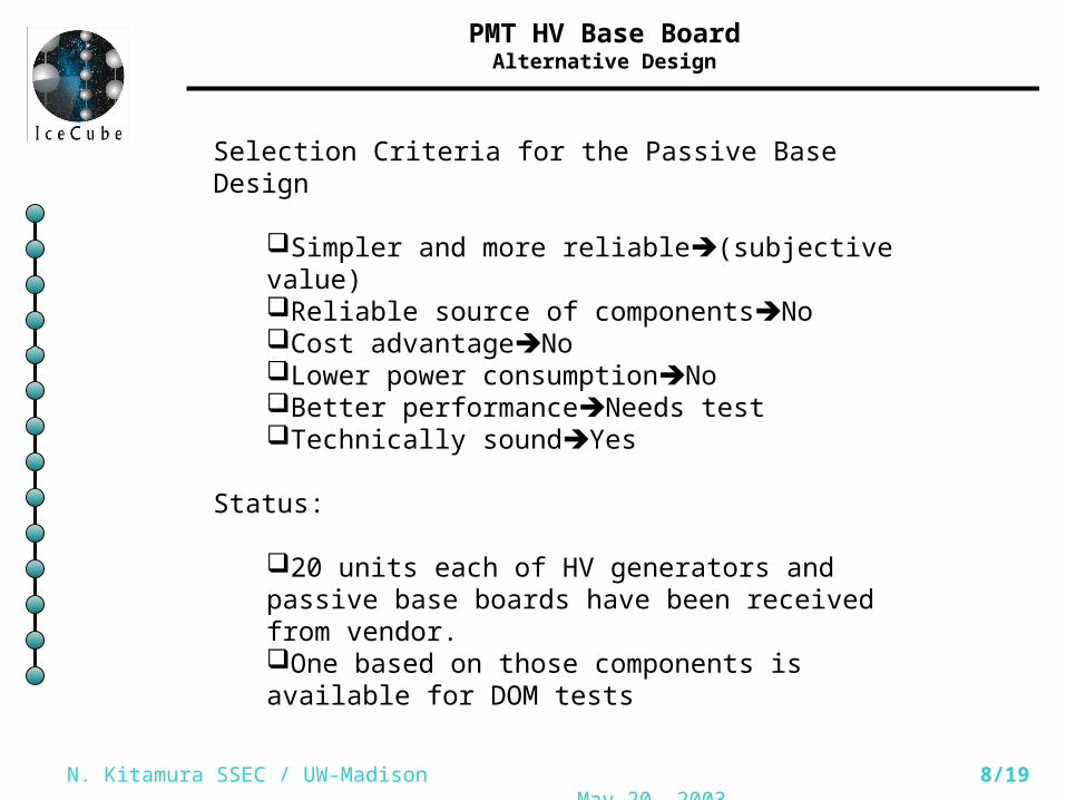
Selection Criteria for the Passive Base Design
Simpler and more reliable(subjective value)Reliable source of componentsNoCost advantageNoLower power consumptionNoBetter performanceNeeds testTechnically soundYes
Status:
20 units each of HV generators and passive base boards have been received from vendor.One based on those components is available for DOM tests

N. Kitamura SSEC / UW-Madison May 20, 2003
9/19
Known Design / Requirements Issue No.1
3.2.2.1 Split-ground requirement
Justification:Avoid ground loopAvoid oscillator noise
Counter argument:Ground loop can be avoided by other meansOscillator noise will propagate anyway
Vendor response:Isolation amplifier adds much to the board power needs and the costLeads to lower feedback gain and poorer voltage regulation
Fig 3.1, page 13
Verification:Comparison of noise levels between configurations w/ and w/o the requirement in question.

N. Kitamura SSEC / UW-Madison May 20, 2003
10/19
Known Design / Requirements Issue No.2
3.2.3.1 Signal coupling with a coaxial toroidal transformer
Justification:•Superior pulse response compared to capacitive coupling•An alternative using a large HV capacitor is a reliability concern
3.2.3.1.B Transformer specification (use RG-178 coaxial cable)
•RG-178 has a maximum operating voltage of only1000Vrms (RF).•Can’t find a suitable, thin, flexible cable with Vmax>2000VDC.
Observation:A sample of RG-178 has been lab tested w/o failureThe Teflon dielectric should withstand well over 2000VThe 1000Vrms at RF is a much harsher condition than 2000VDC
N. Kitamura SSEC / UW-Madison May 20, 2003
11/19
Requirements Update
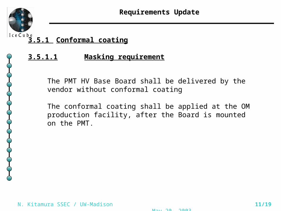
3.5.1 Conformal coating
3.5.1.1 Masking requirement
The PMT HV Base Board shall be delivered by the vendor without conformal coating
The conformal coating shall be applied at the OM production facility, after the Board is mounted on the PMT.

N. Kitamura SSEC / UW-Madison May 20, 2003
12/19
Summary of Physical Interface / Electrical, Mechanical
Table 2.1, page 8.
Connection method Comments Section
Plated-thru PMT mounting holes
Serves both Electrical and Mechanical purposes
3.2.4
Coaxial cable for PMT pulses Carries fast, sensitive pulse signals
3.2.3
2mm ribbon cable Digital and power. Space saver compared to 2.54mm-pitch
3.2.5.2
Clean ground wire Ground for the HV-side of the split ground plane
3.2.2.1.E

N. Kitamura SSEC / UW-Madison May 20, 2003
13/19
3.1 The PMT HV Supply
Justification / Source of requirements
3.1.2 Dynode chain voltage (Table 3.1)
Hamamatsu datasheet
3.1.2.1 Cathode is at ground Low noise advantage
3.1.4.1.A Dy1 fixed at 700VDC PMT measurements at UW to assure P/V
Sufficiently high, allowed by Hamamatsu
Gain adjustment is a needed function
Note 3 (p.25)
3.1.4.1.B Vc-a digitally adjustable 1000-2000VDC
3.1.4.2 HV digital monitor Useful to monitor actual voltage
3.1.5 Anode current sourcing capability
(a), (b) support constant noise current
(c) rare event, allow slow recovery
3.1.6 Stability of 4V/week 2% gain change by analysis
3.1.7 Noise ripple < 0.5mVpp
<< trigger threshold, Note 8
N. Kitamura SSEC / UW-Madison May 20, 2003
14/19
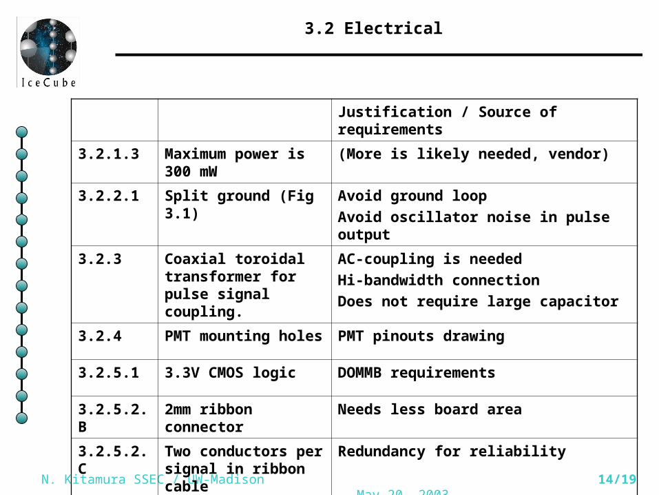
3.2 Electrical
Justification / Source of requirements
3.2.1.3 Maximum power is 300 mW
(More is likely needed, vendor)
3.2.2.1 Split ground (Fig 3.1) Avoid ground loop
Avoid oscillator noise in pulse output
3.2.3 Coaxial toroidal transformer for pulse signal coupling.
AC-coupling is needed
Hi-bandwidth connection
Does not require large capacitor
3.2.4 PMT mounting holes PMT pinouts drawing
3.2.5.1 3.3V CMOS logic DOMMB requirements
3.2.5.2.B 2mm ribbon connector Needs less board area
3.2.5.2.C Two conductors per signal in ribbon cable
Redundancy for reliability

N. Kitamura SSEC / UW-Madison May 20, 2003
15/19
3.2 Electrical (continued)
Justification / Source of requirements
3.2.5.3 Two chip-select lines Support three digital functions (DAC, ADC, IDENT)
3.2.5.5.A Power ON/OFF ON and OFF are both required modes of operation
3.2.5.5.C On power-up the voltage is at minimum supported value
Safe default behavior
3.2.5.6.A Board ID readout DAQ software design
N. Kitamura SSEC / UW-Madison May 20, 2003
16/19
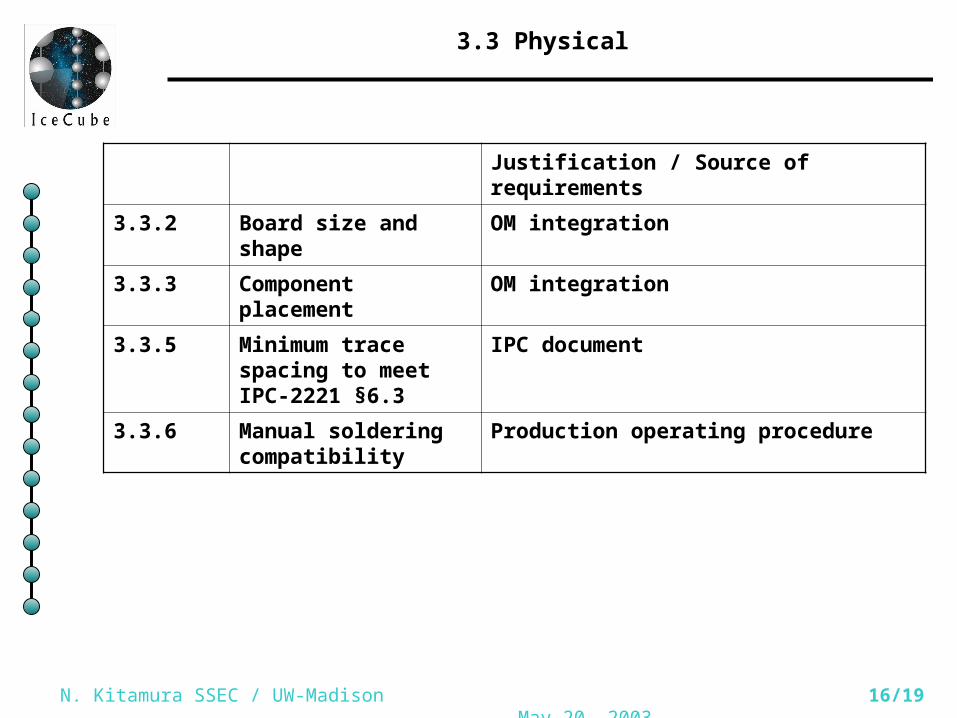
3.3 Physical
Justification / Source of requirements
3.3.2 Board size and shape OM integration
3.3.3 Component placement OM integration
3.3.5 Minimum trace spacing to meet IPC-2221 §6.3
IPC document
3.3.6 Manual soldering compatibility
Production operating procedure

N. Kitamura SSEC / UW-Madison May 20, 2003
17/19
3.4 Environmental
Justification / Source of requirements
3.4.1.1 Operating temperature is –40 to +27C
In-ice operation, excludes icetop
3.4.1.2 Storage temperature is –55 to +45C
Storage and transport environment
3.4.1.3 Prefer components rated below –55C
Vendor must disclose otherwise
3.4.2 Pressure range 40kPa to 100kPa
Actual operating environment

N. Kitamura SSEC / UW-Madison May 20, 2003
18/19
3.5 Miscellaneous
Justification / Source of requirements
3.5.1 Conformal coating is required
The IPC rule assumes dielectric coating
(Coating to be applied at OM production site)
3.5.1.1 Proper masking before applying conformal coat
(Requirement to be removed)
3.5.2 Silkscreen marking Needed for inspection and production

N. Kitamura SSEC / UW-Madison May 20, 2003
19/19
Conclusion
Is the ERD in good shape?
Risk items have been identified:Toroidal transformer requirementSplit ground requirement
AlternativesRequirements are definedSelection logic defined
Test against the Exit Criteria