Preliminary Design Review -...
51
2/26/2006 rit M A V rit Slide 1 Preliminary Design Review Micro Air Vehicle Surveillance Platform RIT Multidisciplinary Senior Design 2005-2006 Project Number P06007 February 24, 2006 Dr. Jeffrey Kozak Project Advisor Dr. Alan Nye Project Coordinator Matteo Blanc Mechanical Engineering Joe Calandro Systems Engineering Adam Gillis Electrical Engineering Shane Healey Mechanical Engineering Josh Joseph Mechanical Engineering Applied Mathematics Mike Koelemay Mechanical Engineering BS/Meng Project Manager John Lemmon Mechanical Engineering Michael Reid Mechanical Engineering BS/MS Andrew Streett Mechanical Engineering BS/MS
Transcript of Preliminary Design Review -...
2/26/2006rit
MAV
rit
Slide 1
Preliminary Design Review
Micro Air Vehicle Surveillance PlatformRIT Multidisciplinary Senior Design 2005-2006
Project Number P06007February 24, 2006
Dr. Jeffrey KozakProject Advisor
Dr. Alan NyeProject Coordinator
Matteo BlancMechanical Engineering
Joe CalandroSystems Engineering
Adam GillisElectrical Engineering
Shane HealeyMechanical Engineering
Josh JosephMechanical EngineeringApplied Mathematics
Mike KoelemayMechanical Engineering BS/MengProject Manager
John LemmonMechanical Engineering
Michael ReidMechanical Engineering BS/MS
Andrew StreettMechanical Engineering BS/MS
2/26/2006rit
MAV
rit
Slide 2
Presentation Outline
• Introduction• Needs Assessment• Concept Development and Feasibility• Subsystems Design Analysis
o Electronicso Aerodynamicso Materials and Manufacturing
• Preliminary Design• Next Steps
2/26/2006rit
MAV
rit
Slide 3
Introduction
• Micro Air Vehicle (MAV) Historyo DARPAo MAV Program Initiative 1996
• International Micro Air Vehicle Competitiono 10th yearo 4 Objectives
SurveillanceEnduranceOrnithopterDesign Report
• RIT Historyo 4th year (3rd in competition)
2/26/2006rit
MAV
rit
Slide 4
Introduction – Team Structure
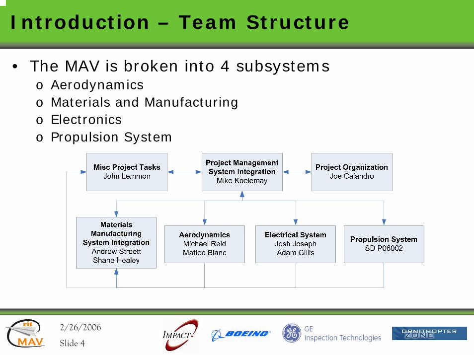
• The MAV is broken into 4 subsystemso Aerodynamicso Materials and Manufacturingo Electronicso Propulsion System
2/26/2006rit
MAV
rit
Slide 5
Competition Objective - Surveillance
• The objective of the competition is to design and build the smallest MAV that can fly and photograph a 1.5-meter sized symbol on the ground located 600 meters from the launch site.
2/26/2006rit
MAV
rit
Slide 6
Needs Assessment
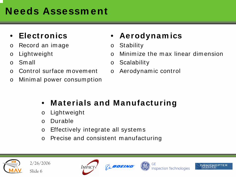
• Electronicso Record an imageo Lightweighto Smallo Control surface movemento Minimal power consumption
• Aerodynamicso Stabilityo Minimize the max linear dimensiono Scalabilityo Aerodynamic control
• Materials and Manufacturingo Lightweighto Durableo Effectively integrate all systemso Precise and consistent manufacturing

2/26/2006rit
MAV
rit
Slide 7
Concept Development and Feasibility –Combined System
• Quality Function Deployment, Phase I• Quality Function Deployment, Phase II• Morphological Analysis• Pugh Analysis
QFD1, QFD2, MA, PA1, PA2
2/26/2006rit
MAV
rit
Slide 8
Concept Development and Feasibility –Combined System
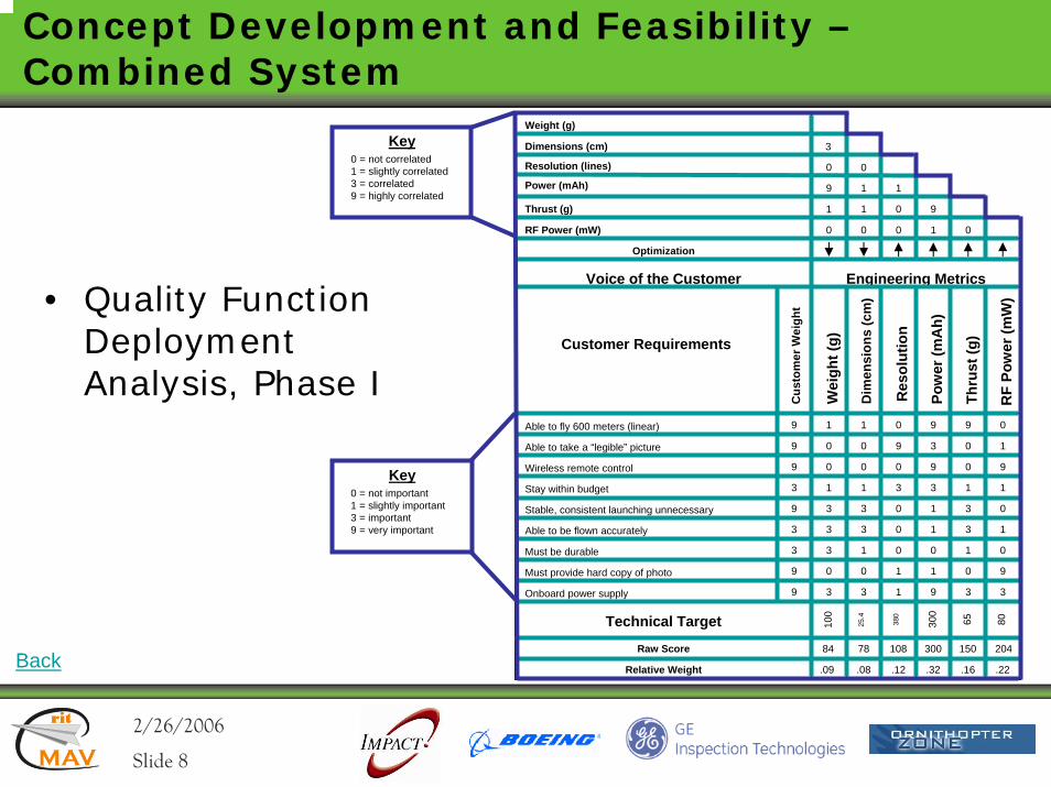
• Quality Function Deployment Analysis, Phase I
Key0 = not important1 = slightly important3 = important9 = very important
Customer Requirements
Able to fly 600 meters (linear)
Able to take a “legible” picture
Wireless remote control
Stay within budget
Stable, consistent launching unnecessary
Able to be flown accurately
Must be durable
Must provide hard copy of photo
Onboard power supply
Cus
tom
er W
eigh
t
9
9
9
3
9
3
3
9
9
Engineering Metrics
Wei
ght (
g)
Dim
ensi
ons
(cm
)
Res
olut
ion
Pow
er (m
Ah)
Thru
st (g
)
RF
Pow
er (m
W)
1
0
0
1
3
3
3
0
3
1
0
0
1
3
3
1
0
3
Voice of the Customer
0
9
0
3
0
0
0
1
1
9
3
9
3
1
1
0
1
9
9
0
0
1
3
3
1
0
3
0
1
9
1
0
1
0
9
3
Technical Target 80
Weight (g)
Dimensions (cm)
Resolution (lines)
Power (mAh)
Thrust (g)
RF Power (mW)
Optimization
3
0
1
9
0
0
9
1
0
1
1
0
0
0 1
Key0 = not correlated1 = slightly correlated3 = correlated9 = highly correlated
65300
380
25.4
100
Raw Score
Relative Weight
84 78 108 300 150 204
.09 .08 .12 .32 .16 .22Back
2/26/2006rit
MAV
rit
Slide 9
Concept Development and Feasibility –Combined System
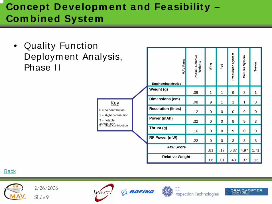
• Quality Function Deployment Analysis, Phase II
Engineering Metrics
Phas
e I R
elat
ive
Wei
ghts
Weight (g)
Dimensions (cm)
Resolution (lines)
Power (mAh)
Thrust (g)
RF Power (mW)
Raw Score
Relative Weight
Win
g
Pod
Prop
ulsi
on S
yste
m
Cam
era
Syst
em
Serv
os
MA
V Pa
rts
.09
.08
.12
.32
.16
.22
1 1 9 3 1
9 1 1 1 0
0 0 0 9 0
0 0 9 9 3
0 0 9 0 0
0 0 3 3 3
Key0 = no contribution
1 = slight contribution
3 = notable contribution9 = large contribution
.81 .17 5.87 4.97 1.71
.06 .01 .43 .37 .13
Back
2/26/2006rit
MAV
rit
Slide 10
Concept Development and Feasibility –Combined System
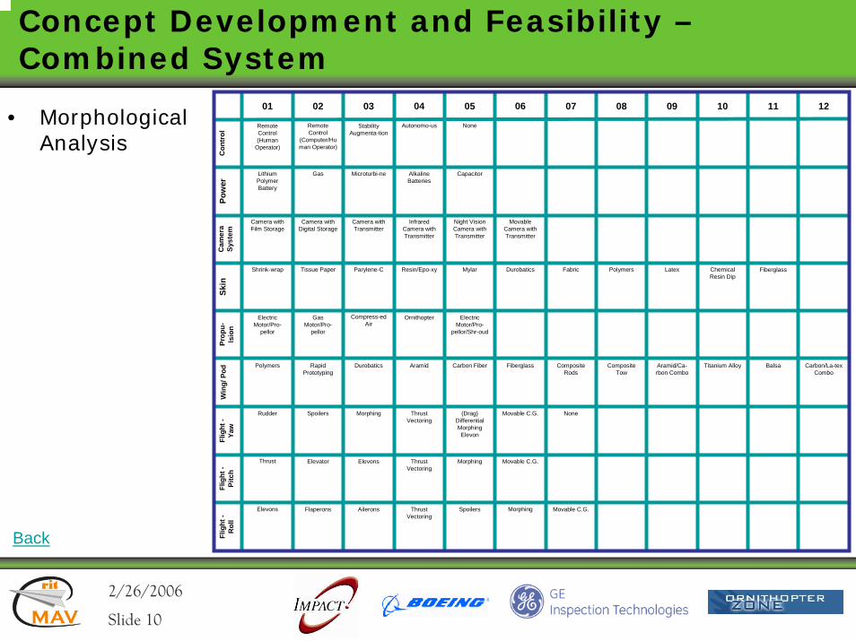
• Morphological Analysis
Con
trol
Pow
erC
amer
a Sy
stem
Skin
Prop
u-ls
ion
Win
g/ P
odFl
ight
-Ya
wFl
ight
-Pi
tch
Flig
ht -
Rol
l
02 03 0401 05 06 07 08 09 10 11 12
Remote Control (Human
Operator)
Remote Control
(Computer/Human Operator)
Stability Augmenta-tion
Autonomo-us None
Lithium Polymer Battery
Gas Microturbi-ne Alkaline Batteries
Capacitor
Camera with Film Storage
Camera with Digital Storage
Camera with Transmitter
Infrared Camera with Transmitter
Night Vision Camera with Transmitter
Movable Camera with Transmitter
Shrink-wrap Tissue Paper Parylene-C Resin/Epo-xy Mylar Durobatics Fabric Polymers Latex Chemical Resin Dip
Electric Motor/Pro-
pellor
Gas Motor/Pro-
pellor
Compress-ed Air
Ornithopter Electric Motor/Pro-
pellor/Shr-oud
Polymers Rapid Prototyping
Durobatics Aramid Carbon Fiber Fiberglass Composite Rods
Composite Tow
Aramid/Ca-rbon Combo
Titanium Alloy Balsa Carbon/La-texCombo
Rudder Spoilers Morphing Thrust Vectoring
(Drag) Differential Morphing Elevon
Movable C.G.
Thrust Elevator Elevons Thrust Vectoring
Morphing Movable C.G.
Elevons Flaperons Ailerons Thrust Vectoring
Spoilers Morphing Movable C.G.
Fiberglass
None
Back
2/26/2006rit
MAV
rit
Slide 11
Concept Development and Feasibility –Combined System
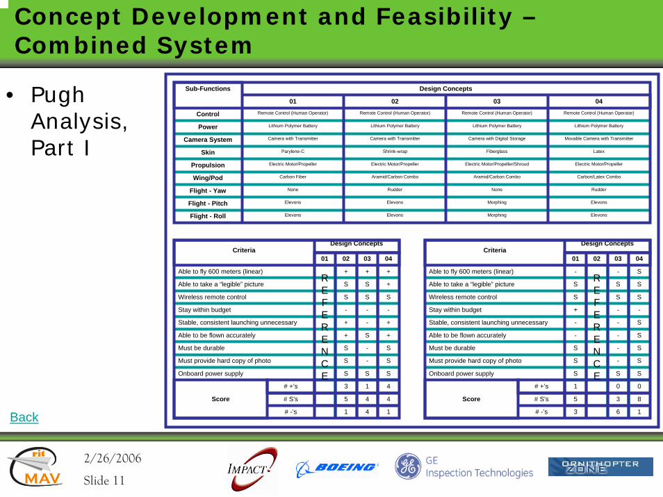
• Pugh Analysis, Part I
Design Concepts
01
Control
Power
Camera System
Skin
Propulsion
Wing/Pod
Flight - Yaw
Flight - Pitch
Flight - Roll
Sub-Functions
Remote Control (Human Operator)
02 03 04
Lithium Polymer Battery
Camera with Transmitter
Parylene-C
Electric Motor/Propeller
Carbon Fiber
Rudder
Elevons
Elevons
Remote Control (Human Operator)
Lithium Polymer Battery
Camera with Transmitter
Shrink-wrap
Electric Motor/Propeller/Shroud
Aramid/Carbon Combo
Rudder
Elevons
Elevons
Remote Control (Human Operator)
Lithium Polymer Battery
Camera with Digital Storage
Fiberglass
Electric Motor/Propeller
Aramid/Carbon Combo
None
Elevons
Elevons
Remote Control (Human Operator)
Lithium Polymer Battery
Movable Camera with Transmitter
Latex
Electric Motor/Propeller
Carbon/Latex Combo
None
Morphing
Morphing
Criteria
Able to fly 600 meters (linear)
Able to take a “legible” picture
Wireless remote control
Stay within budget
Stable, consistent launching unnecessary
Able to be flown accurately
Must be durable
Must provide hard copy of photo
Onboard power supply
Score
# +’s
# S’s
# -’s
01 02 03 04
Design Concepts
S S +
+ +
S S S
- -
+ - +
+ S +
S - S
S - S
S S S
3 1 4
5 4 4
1 4 1
Criteria
Able to fly 600 meters (linear)
Able to take a “legible” picture
Wireless remote control
Stay within budget
Stable, consistent launching unnecessary
Able to be flown accurately
Must be durable
Must provide hard copy of photo
Onboard power supply
Score
# +’s
# S’s
# -’s
01 02 03 04
Design Concepts
S S S
- - S
S S S
+ - -
- - S
- - S
S - S
S - S
S S S
1 0 0
5 3 8
3 6 1
REFERENCE
REFERENCE
+
-
Back
2/26/2006rit
MAV
rit
Slide 12
Concept Development and Feasibility –Combined System
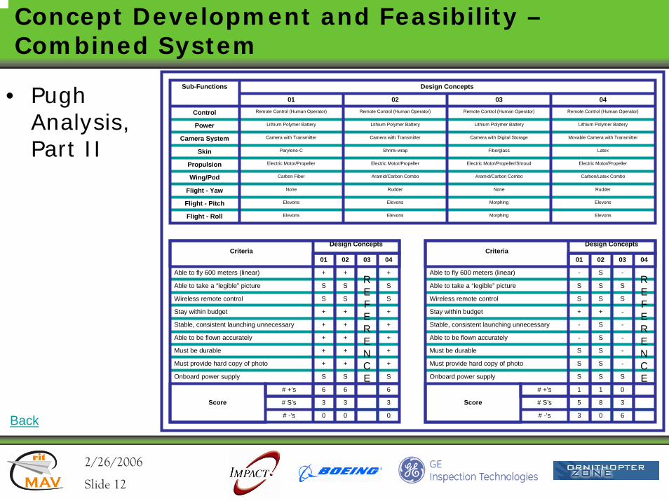
• Pugh Analysis, Part II
Criteria
Able to fly 600 meters (linear)
Able to take a “legible” picture
Wireless remote control
Stay within budget
Stable, consistent launching unnecessary
Able to be flown accurately
Must be durable
Must provide hard copy of photo
Onboard power supply
Score
# +’s
# S’s
# -’s
01 02 03 04
Design Concepts
SS S
++ +
SS S
++ +
++
++ +
++ +
++
SS S
66 6
33 3
00 0
Criteria
Able to fly 600 meters (linear)
Able to take a “legible” picture
Wireless remote control
Stay within budget
Stable, consistent launching unnecessary
Able to be flown accurately
Must be durable
Must provide hard copy of photo
Onboard power supply
Score
# +’s
# S’s
# -’s
01 02 03 04
Design Concepts
S SS
S --
S SS
+ -+
S --
S --
S -S
S -S
S SS
1 01
8 35
0 63
RE F ERENCE
RE F ERENCE
+
+
Design Concepts
01
Control
Power
Camera System
Skin
Propulsion
Wing/Pod
Flight - Yaw
Flight - Pitch
Flight - Roll
Sub-Functions
Remote Control (Human Operator)
02 03 04
Lithium Polymer Battery
Camera with Transmitter
Parylene-C
Electric Motor/Propeller
Carbon Fiber
Rudder
Elevons
Elevons
Remote Control (Human Operator)
Lithium Polymer Battery
Camera with Transmitter
Shrink-wrap
Electric Motor/Propeller/Shroud
Aramid/Carbon Combo
Rudder
Elevons
Elevons
Remote Control (Human Operator)
Lithium Polymer Battery
Camera with Digital Storage
Fiberglass
Electric Motor/Propeller
Aramid/Carbon Combo
None
Elevons
Elevons
Remote Control (Human Operator)
Lithium Polymer Battery
Movable Camera with Transmitter
Latex
Electric Motor/Propeller
Carbon/Latex Combo
None
Morphing
Morphing
Back
2/26/2006rit
MAV
rit
Slide 13
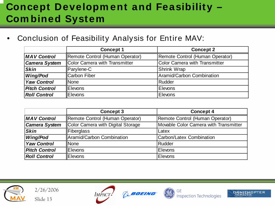
Concept Development and Feasibility –Combined System
• Conclusion of Feasibility Analysis for Entire MAV:Concept 1 Concept 2
MAV Control Remote Control (Human Operator) Remote Control (Human Operator)Camera System Color Camera with Transmitter Color Camera with TransmitterSkin Parylene-C Shrink WrapWing/Pod Carbon Fiber Aramid/Carbon CombinationYaw Control None RudderPitch Control Elevons ElevonsRoll Control Elevons Elevons
Concept 3 Concept 4MAV Control Remote Control (Human Operator) Remote Control (Human Operator)Camera System Color Camera with Digital Storage Movable Color Camera with TransmitterSkin Fiberglass LatexWing/Pod Aramid/Carbon Combination Carbon/Latex CombinationYaw Control None RudderPitch Control Elevons ElevonsRoll Control Elevons Elevons
2/26/2006rit
MAV
rit
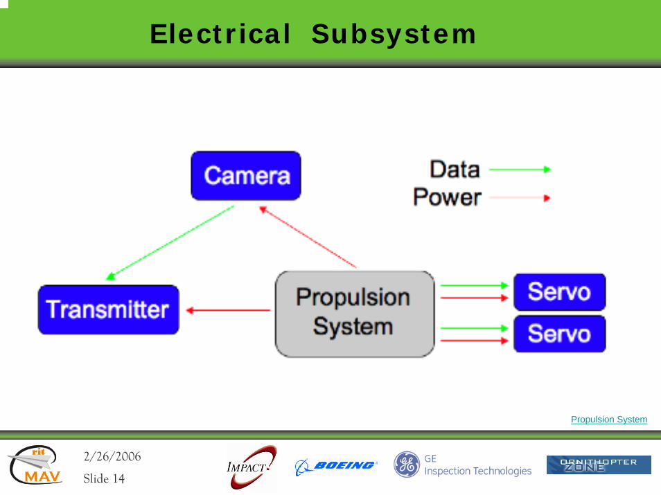
Slide 14
Electrical Subsystem
Propulsion System
2/26/2006rit
MAV
rit
Slide 15
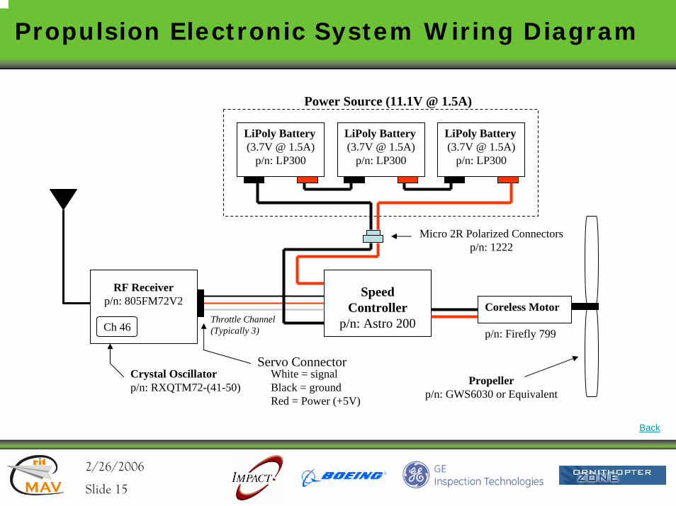
Propulsion Electronic System Wiring Diagram
p/n: Firefly 799
Coreless MotorSpeed
Controllerp/n: Astro 200
LiPoly Battery(3.7V @ 1.5A)
p/n: LP300
LiPoly Battery(3.7V @ 1.5A)
p/n: LP300
LiPoly Battery(3.7V @ 1.5A)
p/n: LP300
Power Source (11.1V @ 1.5A)
Micro 2R Polarized Connectors p/n: 1222
RF Receiverp/n: 805FM72V2
Throttle Channel (Typically 3)
Servo Connector
Ch 46
Crystal Oscillatorp/n: RXQTM72-(41-50)
White = signalBlack = groundRed = Power (+5V)
Propellerp/n: GWS6030 or Equivalent
Back
2/26/2006rit
MAV
rit
Slide 16
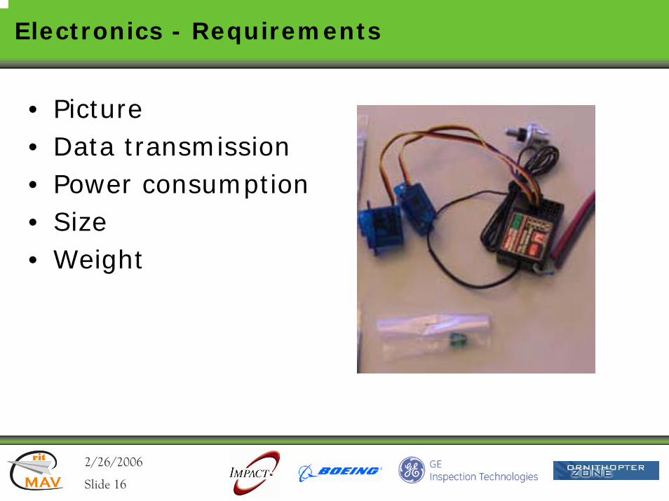
Electronics - Requirements
• Picture• Data transmission• Power consumption• Size• Weight
2/26/2006rit
MAV
rit
Slide 17
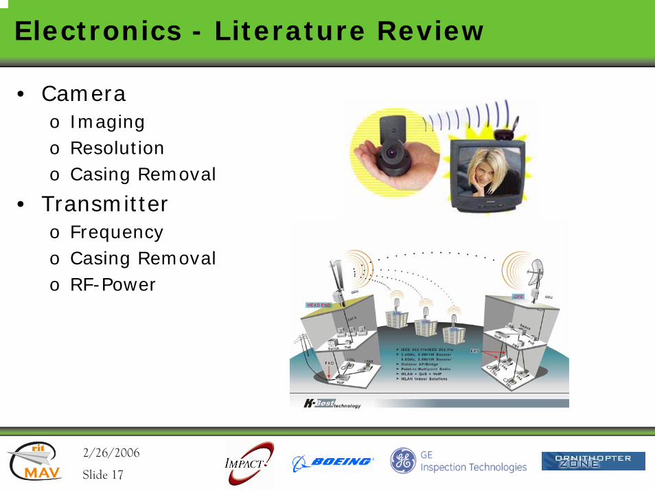
Electronics - Literature Review
• Camerao Imagingo Resolutiono Casing Removal
• Transmittero Frequencyo Casing Removalo RF-Power
2/26/2006rit
MAV
rit
Slide 18
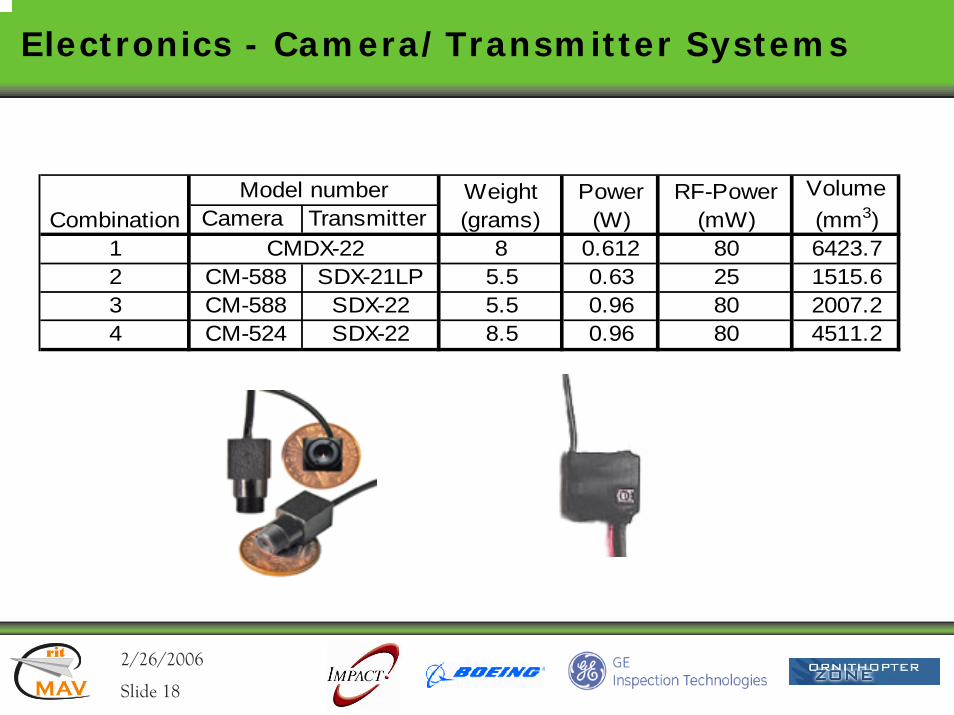
Electronics - Camera/Transmitter Systems
Camera Transmitter 1 8 0.612 80 6423.72 CM-588 SDX-21LP 5.5 0.63 25 1515.63 CM-588 SDX-22 5.5 0.96 80 2007.24 CM-524 SDX-22 8.5 0.96 80 4511.2
RF-Power (mW)
Volume (mm3)Combination
Model number
CMDX-22
Weight (grams)
Power (W)
2/26/2006rit
MAV
rit
Slide 19
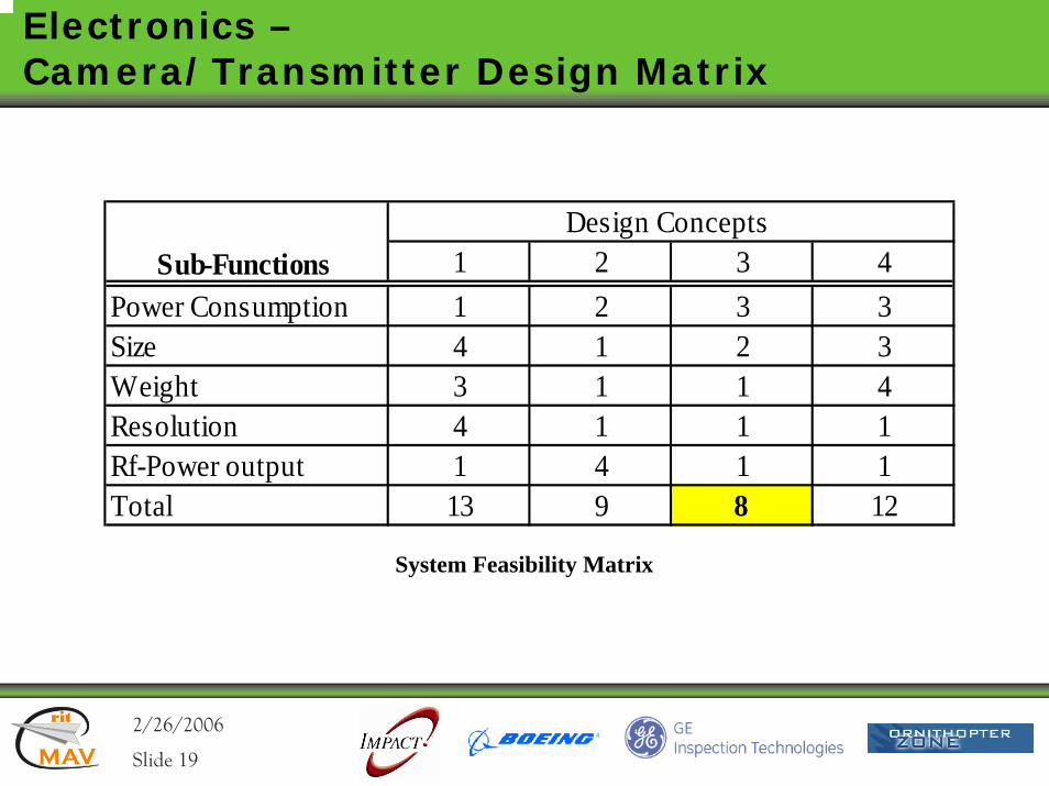
Electronics –Camera/Transmitter Design Matrix
1 2 3 41 2 3 34 1 2 33 1 1 44 1 1 11 4 1 113 9 8 12
Sub-Functions Design Concepts
Power ConsumptionSize Weight
Rf-Power outputTotal
Resolution
System Feasibility Matrix
2/26/2006rit
MAV
rit
Slide 20
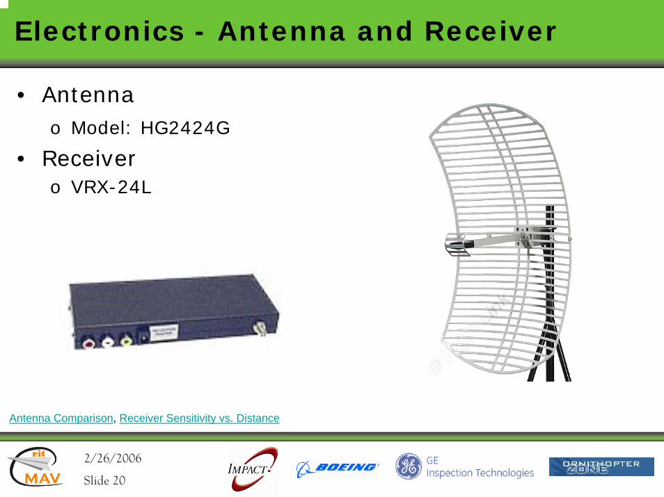
Electronics - Antenna and Receiver
• Antennao Model: HG2424G
• Receivero VRX-24L
Antenna Comparison, Receiver Sensitivity vs. Distance
2/26/2006rit
MAV
rit
Slide 21
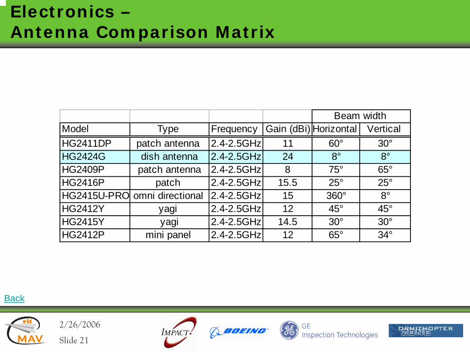
Electronics –Antenna Comparison Matrix
Back
Model Type Frequency Gain (dBi) Horizontal Vertical HG2411DP patch antenna 2.4-2.5GHz 11 60° 30°HG2424G dish antenna 2.4-2.5GHz 24 8° 8°HG2409P patch antenna 2.4-2.5GHz 8 75° 65°HG2416P patch 2.4-2.5GHz 15.5 25° 25°HG2415U-PRO omni directional 2.4-2.5GHz 15 360° 8°HG2412Y yagi 2.4-2.5GHz 12 45° 45°HG2415Y yagi 2.4-2.5GHz 14.5 30° 30°HG2412P mini panel 2.4-2.5GHz 12 65° 34°
Beam width
2/26/2006rit
MAV
rit
Slide 22
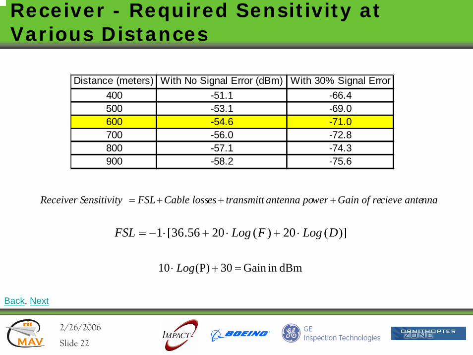
Receiver - Required Sensitivity at Various Distances
Distance (meters) With No Signal Error (dBm) With 30% Signal Error400 -51.1 -66.4500 -53.1 -69.0600 -54.6 -71.0700 -56.0 -72.8800 -57.1 -74.3900 -58.2 -75.6
nnacieve anteGain of rewerantenna potransmitt esCable lossFSL ensitivityReceiver S +++=
dBmin Gain 30)P(10 =+⋅ Log
)](20)(2056.36[1 DLogFLogFSL ⋅+⋅+⋅−=
Back, Next
2/26/2006rit
MAV
rit
Slide 23
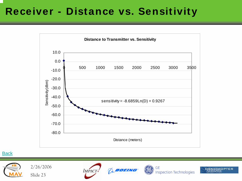
Receiver - Distance vs. Sensitivity
Distance to Transmitter vs. Sensitivity
sensitivity = -8.6859Ln(D) + 0.9267
-80.0
-70.0
-60.0
-50.0
-40.0
-30.0
-20.0
-10.0
0.0
10.0
0 500 1000 1500 2000 2500 3000 3500
Distance (meters)
Sens
itivity
(dbm
)
Back
2/26/2006rit
MAV
rit
Slide 24
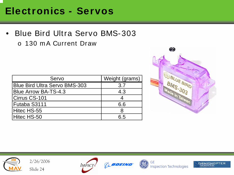
Electronics - Servos
• Blue Bird Ultra Servo BMS-303o 130 mA Current Draw
Servo Weight (grams)Blue Bird Ultra Servo BMS-303 3.7Blue Arrow BA-TS-4.3 4.3Cirrus CS-101 4Futaba S3111 6.6Hitec HS-55 8Hitec HS-50 6.5
2/26/2006rit
MAV
rit
Slide 25
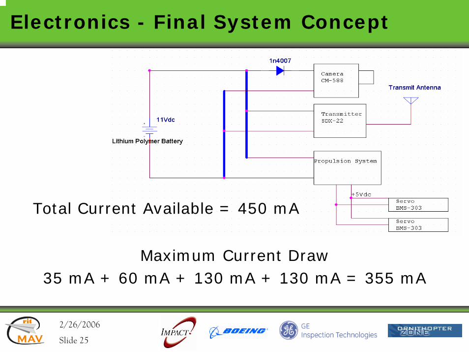
Electronics - Final System Concept
Maximum Current Draw35 mA + 60 mA + 130 mA + 130 mA = 355 mA
Total Current Available = 450 mA
2/26/2006rit
MAV
rit
Slide 26
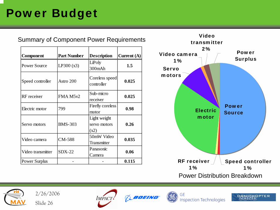
Power Budget
Power Distribution Breakdown
Summary of Component Power Requirements
Video camera1%
Power Surplus
Power Source
RF receiver1%
Speed controller1%
Electric motor
Video transmitter
2%
Servo motors
Component Part Number Description Current (A)
Power Source LP300 (x3)LiPoly 300mAh 1.5
Speed controller Astro 200Coreless speed controller 0.025
RF receiver FMA M5v2 Sub-micro receiver
0.025
Electric motor 799 Firefly coreless motor
0.98
Servo motors BMS-303Light weight servo motors (x2)
0.26
Video camera CM-588 50mW Video Transmitter
0.035
Video transmitter SDX-22 Panasonic Camera
0.06
Power Surplus - - 0.115
2/26/2006rit
MAV
rit
Slide 27
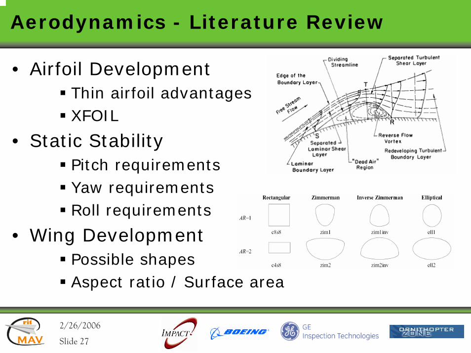
Aerodynamics - Literature Review
• Airfoil DevelopmentThin airfoil advantagesXFOIL
• Static StabilityPitch requirementsYaw requirementsRoll requirements
• Wing DevelopmentPossible shapesAspect ratio / Surface area
2/26/2006rit
MAV
rit
Slide 28
Aerodynamics –Requirements and Specifications
• System LevelGenerate lift in access of weightInsure static stabilityMinimize max linear dimensionScalable platform
• Subsystem LevelAirfoil – maximize CL/CD and ensure pitch stabilityWing – minimize max linear dimension, minimize tip effectsVertical tail – insure yaw stabilityControl surfaces – pitch and roll control, minimize drag effects
Detailed Requirements
2/26/2006rit
MAV
rit
Slide 29
Aerodynamic Requirements
• Aerodynamic Stability:• Must be stable in pitch, yaw, roll• Aircraft will have a positive pitching moment intercept and a negative slope• Elevons shall be effective in controlling pitch rates• Aircraft shall be critically damped in yaw direction• Aircraft yawing moment curve must be positive and 0 intercept• Aircraft shall have a negative rolling moment and 0 intercept• Elevons shall be effective in controlling roll rates• Force on control surfaces shall not exceed force provided by servo• The CG shall be located to ensure stability • Elevon operation shall have minimal effect on yaw• Lift and Drag:• Planform must minimize tip vortices• Size:• Planform that optimizes lift for smallest maximum linear dimension• Endurance:• Maintain stability/lift/drag for the duration of the flight
Back
2/26/2006rit
MAV
rit
Slide 30
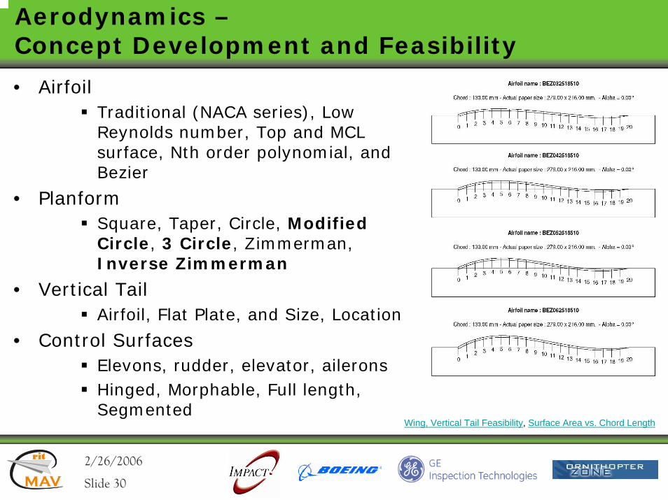
Aerodynamics –Concept Development and Feasibility
• AirfoilTraditional (NACA series), Low Reynolds number, Top and MCL surface, Nth order polynomial, and Bezier
• PlanformSquare, Taper, Circle, Modified Circle, 3 Circle, Zimmerman, Inverse Zimmerman
• Vertical TailAirfoil, Flat Plate, and Size, Location
• Control SurfacesElevons, rudder, elevator, aileronsHinged, Morphable, Full length, Segmented
Wing, Vertical Tail Feasibility, Surface Area vs. Chord Length
2/26/2006rit
MAV
rit
Slide 31
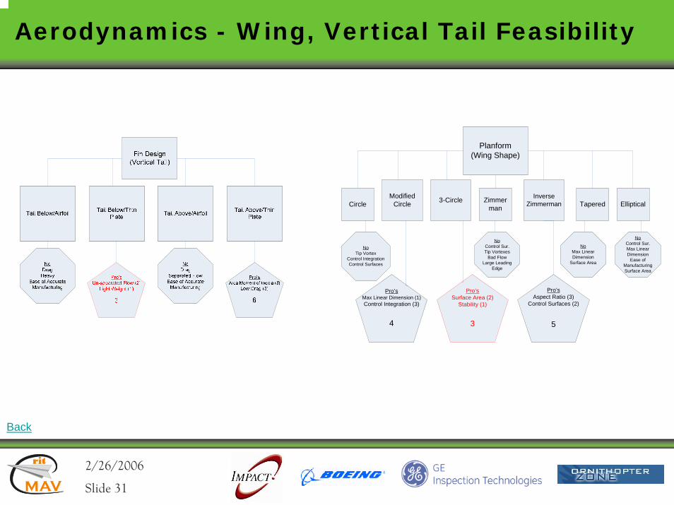
Aerodynamics - Wing, Vertical Tail Feasibility
Planform(Wing Shape)
CircleInverse
Zimmerman3-CircleModified Circle Zimmer
man EllipticalTapered
NoTip Vortex
Control IntegrationControl Surfaces
Pro’sMax Linear Dimension (1)Control Integration (3)
4
Pro’sSurface Area (2)
Stability (1)
3
Pro’sAspect Ratio (3)
Control Surfaces (2)
5
NoControl Sur.Tip Vortexes
Bad FlowLarge Leading
Edge
NoMax Linear Dimension
Surface Area
NoControl Sur.Max Linear Dimension
Ease of ManufacturingSurface Area
Back
2/26/2006rit
MAV
rit
Slide 32
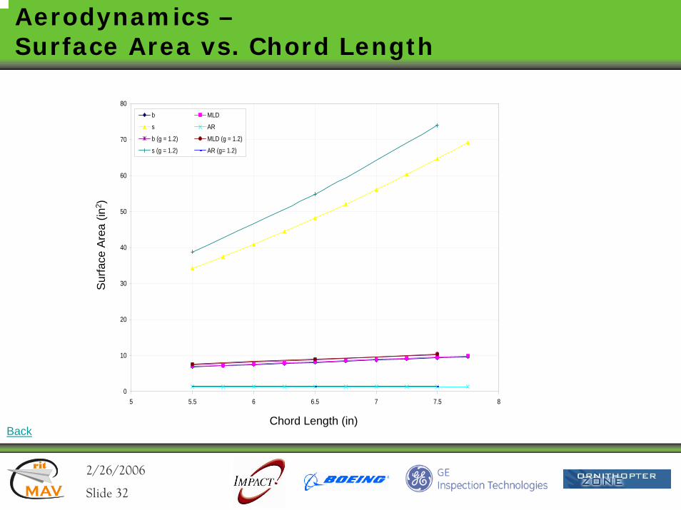
Aerodynamics –Surface Area vs. Chord Length
0
10
20
30
40
50
60
70
80
5 5.5 6 6.5 7 7.5 8
b MLD
s AR
b (g = 1.2) MLD (g = 1.2)
s (g = 1.2) AR (g= 1.2)
Sur
face
Are
a (in
2 )
Chord Length (in)Back
2/26/2006rit
MAV
rit
Slide 33
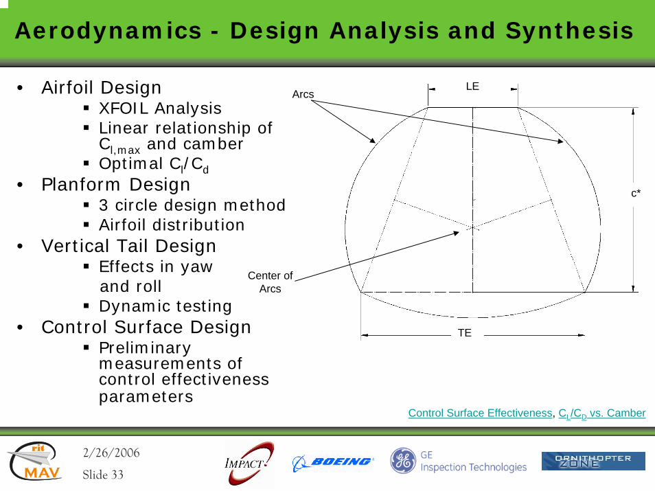
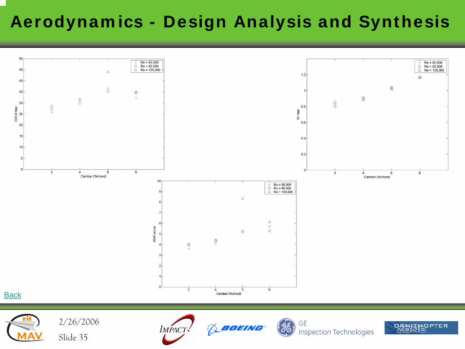
Aerodynamics - Design Analysis and Synthesis
• Airfoil DesignXFOIL AnalysisLinear relationship of Cl,max and camberOptimal Cl/Cd
• Planform Design3 circle design methodAirfoil distribution
• Vertical Tail Design Effects in yawand rollDynamic testing
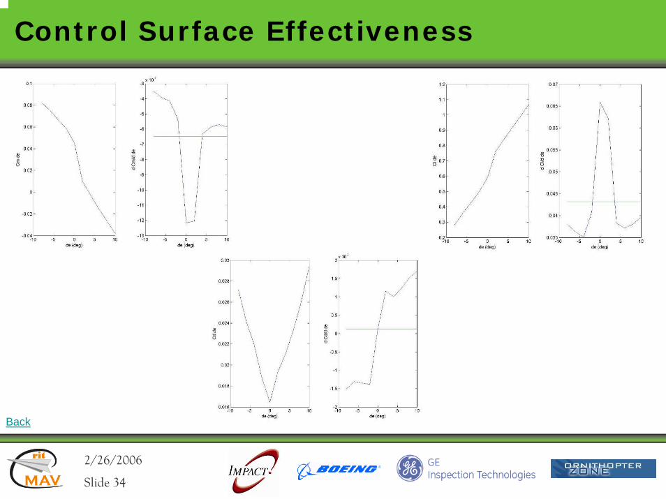
• Control Surface DesignPreliminary measurements of control effectiveness parameters
Arcs
c*
LE
TE
Center of Arcs
Control Surface Effectiveness, CL/CD vs. Camber
2/26/2006rit
MAV
rit
Slide 34
Control Surface Effectiveness
Back
2/26/2006rit
MAV
rit
Slide 35
Aerodynamics - Design Analysis and Synthesis
Back
2/26/2006rit
MAV
rit
Slide 36
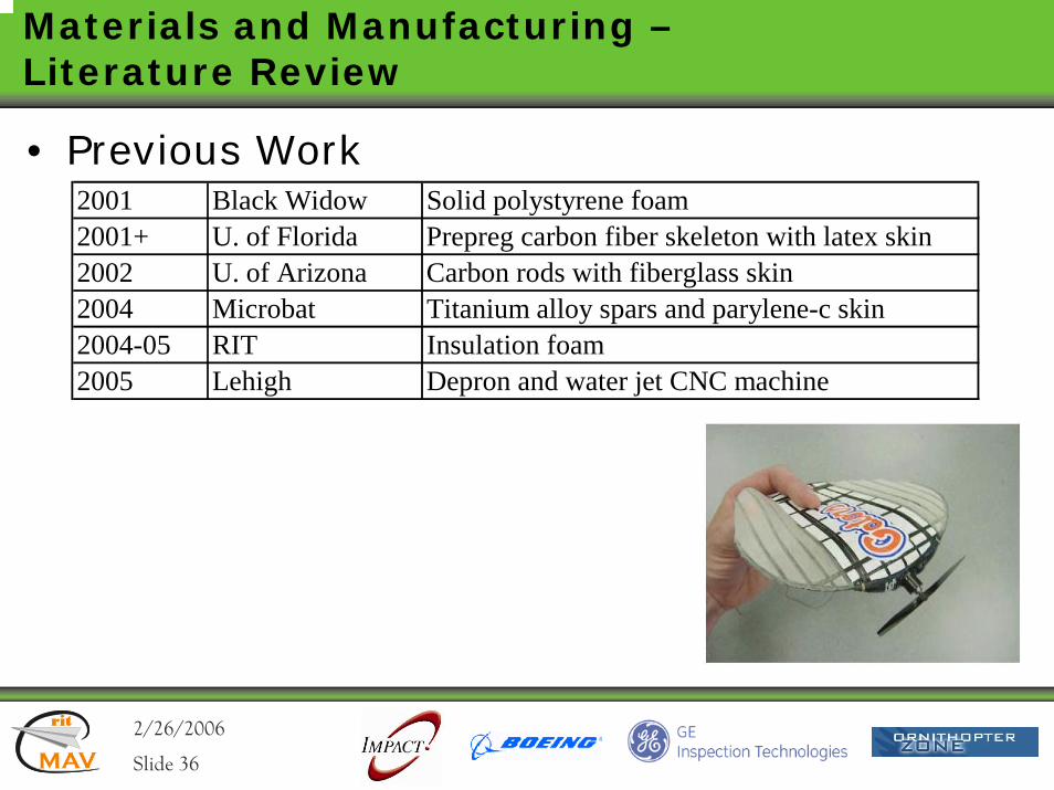
Materials and Manufacturing –Literature Review
• Previous Work2001 Black Widow Solid polystyrene foam 2001+ U. of Florida Prepreg carbon fiber skeleton with latex skin 2002 U. of Arizona Carbon rods with fiberglass skin 2004 Microbat Titanium alloy spars and parylene-c skin 2004-05 RIT Insulation foam2005 Lehigh Depron and water jet CNC machine
2/26/2006rit
MAV
rit
Slide 37
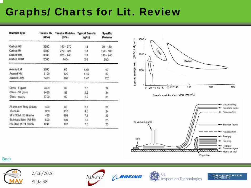
Materials and Manufacturing –Literature Review
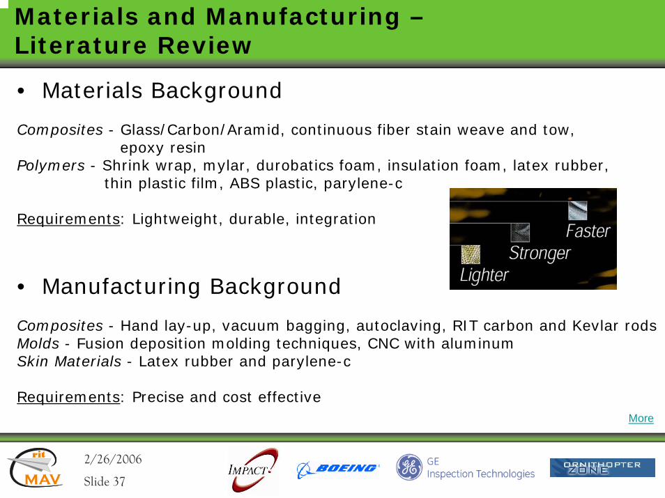
• Materials Background
Composites - Glass/Carbon/Aramid, continuous fiber stain weave and tow, epoxy resin
Polymers - Shrink wrap, mylar, durobatics foam, insulation foam, latex rubber, thin plastic film, ABS plastic, parylene-c
Requirements: Lightweight, durable, integration
• Manufacturing Background
Composites - Hand lay-up, vacuum bagging, autoclaving, RIT carbon and Kevlar rodsMolds - Fusion deposition molding techniques, CNC with aluminum Skin Materials - Latex rubber and parylene-c
Requirements: Precise and cost effectiveMore
2/26/2006rit
MAV
rit
Slide 38
Graphs/Charts for Lit. Review
Back

2/26/2006rit
MAV
rit
Slide 39
Materials and Manufacturing –Concept Development and Feasibility
• Wing Skeleton/Control SurfacesRequirements: 1. Adhere to Aerodynamics Specifications and Planform Size/Shape2. Durable, Lightweight and Effective in Dynamic Loading3. Resolve Connectivity issues
Feasible Materials Assessed:Fiberglass, Carbon, Aramid, Carbon/Aramid – Tow and Satin Weave
Specific Specific Specific Low Shear in-plane & Materials: Strength Stiffness Modulus Density interlaminarFiberglass 2 3 3 3 1 12Carbon Fiber 1 1 1 2 1 6Aramid 1 3 2 1 2 9Carbon/Aramid 2 2 2 2 1 9
Totals
Skeleton Material Properties Feasibility Chart
2/26/2006rit
MAV
rit
Slide 40
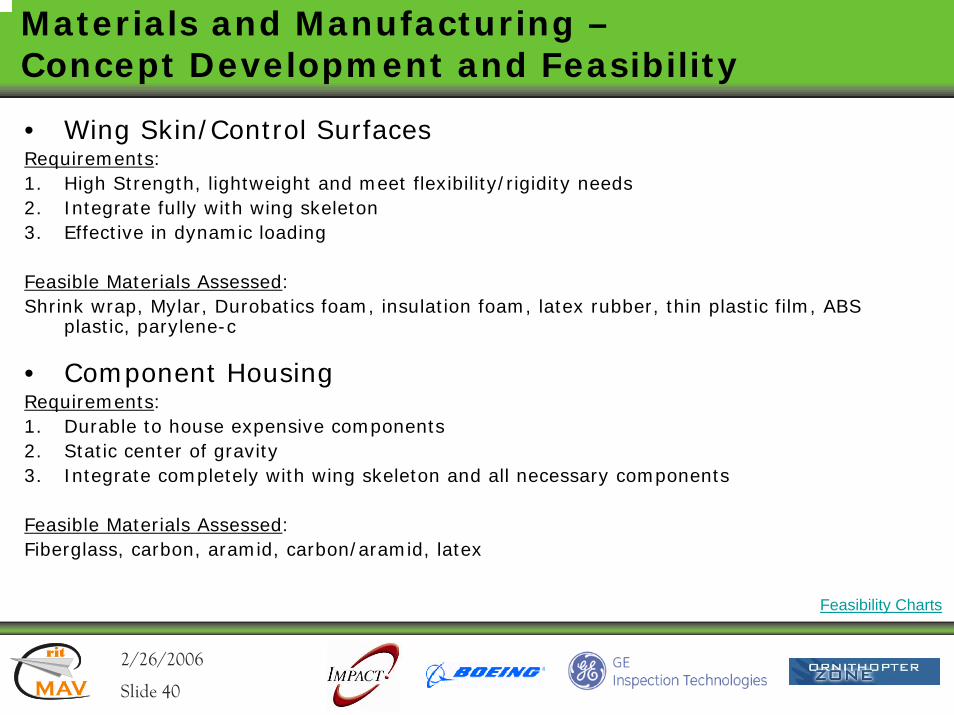
Materials and Manufacturing –Concept Development and Feasibility
• Wing Skin/Control SurfacesRequirements: 1. High Strength, lightweight and meet flexibility/rigidity needs2. Integrate fully with wing skeleton3. Effective in dynamic loading
Feasible Materials Assessed:Shrink wrap, Mylar, Durobatics foam, insulation foam, latex rubber, thin plastic film, ABS
plastic, parylene-c
• Component HousingRequirements: 1. Durable to house expensive components2. Static center of gravity3. Integrate completely with wing skeleton and all necessary components
Feasible Materials Assessed:Fiberglass, carbon, aramid, carbon/aramid, latex
Feasibility Charts
2/26/2006rit
MAV
rit
Slide 41
Materials and Manufacturing –Concept Development and Feasibility
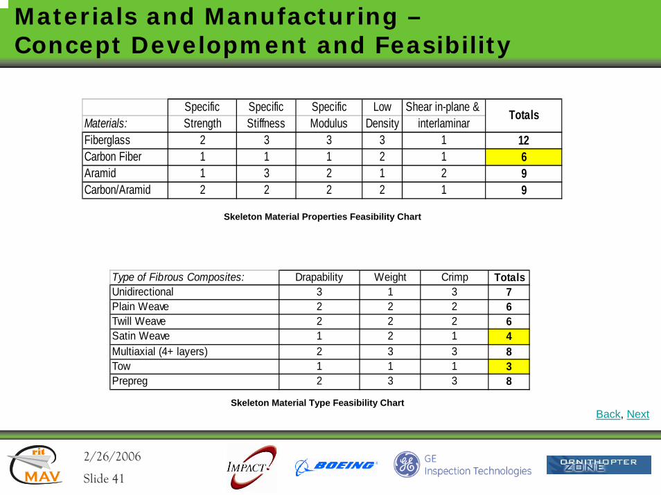
Specific Specific Specific Low Shear in-plane & Materials: Strength Stiffness Modulus Density interlaminarFiberglass 2 3 3 3 1 12Carbon Fiber 1 1 1 2 1 6Aramid 1 3 2 1 2 9Carbon/Aramid 2 2 2 2 1 9
Totals
Skeleton Material Properties Feasibility Chart
Type of Fibrous Composites: Drapability Weight Crimp TotalsUnidirectional 3 1 3 7Plain Weave 2 2 2 6Twill Weave 2 2 2 6Satin Weave 1 2 1 4Multiaxial (4+ layers) 2 3 3 8Tow 1 1 1 3Prepreg 2 3 3 8
Skeleton Material Type Feasibility ChartBack, Next
2/26/2006rit
MAV
rit
Slide 42
Materials and Manufacturing –Concept Development and Feasibility
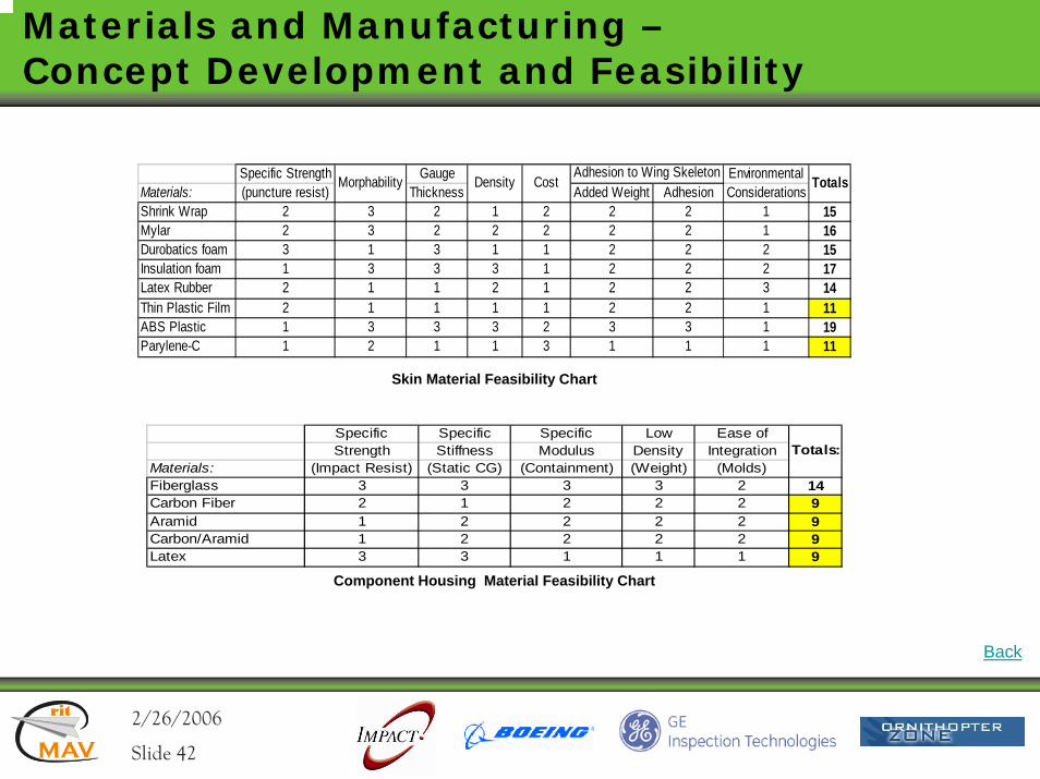
Specific Strength Gauge EnvironmentalMaterials: (puncture resist) Thickness Added Weight Adhesion ConsiderationsShrink Wrap 2 3 2 1 2 2 2 1 15Mylar 2 3 2 2 2 2 2 1 16Durobatics foam 3 1 3 1 1 2 2 2 15Insulation foam 1 3 3 3 1 2 2 2 17Latex Rubber 2 1 1 2 1 2 2 3 14Thin Plastic Film 2 1 1 1 1 2 2 1 11ABS Plastic 1 3 3 3 2 3 3 1 19Parylene-C 1 2 1 1 3 1 1 1 11
TotalsAdhesion to Wing Skeleton
Morphability Density Cost
Skin Material Feasibility Chart
Specific Specific Specific Low Ease ofStrength Stiffness Modulus Density Integration
Materials: (Impact Resist) (Static CG) (Containment) (Weight) (Molds)Fiberglass 3 3 3 3 2 14Carbon Fiber 2 1 2 2 2 9Aramid 1 2 2 2 2 9Carbon/Aramid 1 2 2 2 2 9Latex 3 3 1 1 1 9
Totals:
Component Housing Material Feasibility Chart
Back
2/26/2006rit
MAV
rit
Slide 43
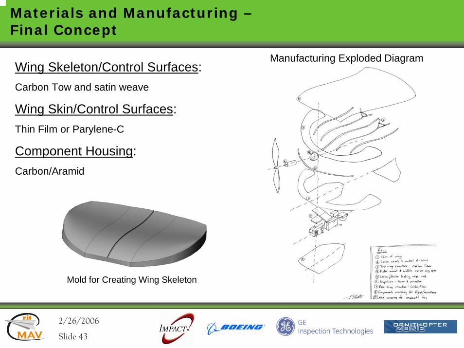
Materials and Manufacturing –Final Concept
Wing Skeleton/Control Surfaces: Carbon Tow and satin weave
Wing Skin/Control Surfaces: Thin Film or Parylene-C
Component Housing:Carbon/Aramid
Manufacturing Exploded Diagram
Mold for Creating Wing Skeleton
2/26/2006rit
MAV
rit
Slide 44
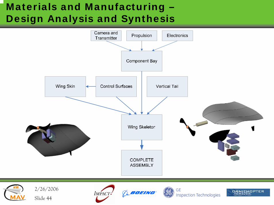
Materials and Manufacturing –Design Analysis and Synthesis
2/26/2006rit
MAV
rit
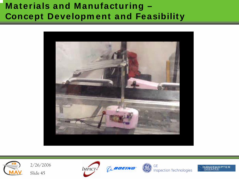
Slide 45
Materials and Manufacturing –Concept Development and Feasibility
2/26/2006rit
MAV
rit
Slide 46
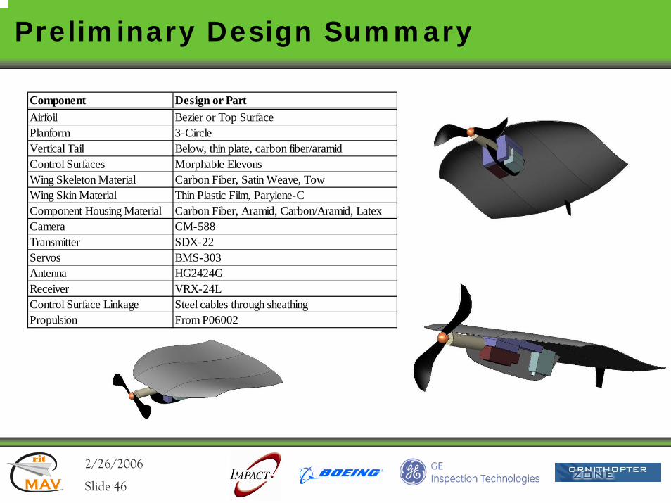
Preliminary Design Summary
Component Design or PartAirfoil Bezier or Top SurfacePlanform 3-CircleVertical Tail Below, thin plate, carbon fiber/aramidControl Surfaces Morphable ElevonsWing Skeleton Material Carbon Fiber, Satin Weave, TowWing Skin Material Thin Plastic Film, Parylene-CComponent Housing Material Carbon Fiber, Aramid, Carbon/Aramid, LatexCamera CM-588Transmitter SDX-22Servos BMS-303Antenna HG2424GReceiver VRX-24LControl Surface Linkage Steel cables through sheathingPropulsion From P06002
2/26/2006rit
MAV
rit
Slide 47
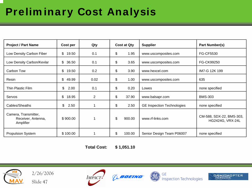
Preliminary Cost Analysis
Project / Part Name Cost per Qty Cost at Qty Supplier Part Number(s)
Low Density Carbon Fiber $ 19.50 0.1 $ 1.95 www.uscomposites.com FG-CF5530
Low Density Carbon/Kevlar $ 36.50 0.1 $ 3.65 www.uscomposites.com FG-CK99250
Carbon Tow $ 19.50 0.2 $ 3.90 www.hexcel.com IM7-G 12K 199
Resin $ 49.99 0.02 $ 1.00 www.uscomposites.com 635
Thin Plastic Film $ 2.00 0.1 $ 0.20 Lowes none specified
Servos $ 18.95 2 $ 37.90 www.balsapr.com BMS-303
Cables/Sheaths $ 2.50 1 $ 2.50 GE Inspection Technologies none specified
Camera, Transmitter, Receiver, Antenna, Amplifier
$ 900.00 1 $ 900.00 www.rf-links.com CM-588, SDX-22, BMS-303, HG2424G, VRX-24L
Propulsion System $ 100.00 1 $ 100.00 Senior Design Team P06007 none specified
Total Cost: $ 1,051.10
2/26/2006rit
MAV
rit
Slide 48
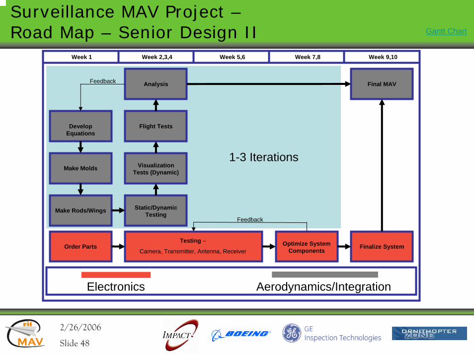
Surveillance MAV Project –Road Map – Senior Design II
Order Parts
Electronics Aerodynamics/Integration
Week 1 Week 5,6 Week 7,8
Optimize System Components
Finalize System
Develop Equations
Make Molds
Make Rods/Wings
Visualization Tests (Dynamic)
Flight Tests
Static/Dynamic Testing
Analysis
Week 2,3,4 Week 9,10
Final MAVFeedback
Testing –
Camera, Transmitter, Antenna, Receiver
1-3 Iterations
Feedback
Gantt Chart
2/26/2006rit
MAV
rit
Slide 49
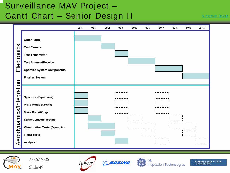
Surveillance MAV Project –Gantt Chart – Senior Design II
Ele
ctro
nics
Aer
odyn
amic
s/In
tegr
atio
nW 1
Flight Tests
Static/Dynamic Testing
Make Molds (Create)
Make Rods/Wings
Specifics (Equations)
Analysis
Visualization Tests (Dynamic)
Finalize System
Order Parts
Test Camera
Test Transmitter
Test Antenna/Receiver
Optimize System Components
W 2 W 3 W 4 W 5 W 6 W 7 W 8 W 9 W 10
Subsystem Details
2/26/2006rit
MAV
rit
Slide 50
Next Steps
• Systemo Manufacturingo Flight testingo Propulsion system integration
• Aerodynamicso Dynamic stability design assessment
• Electronicso Testing transmission rangeso Subsystem integration
2/26/2006rit
MAV
rit
Slide 51
We would like to thank the following sponsors for their generous donations and support!!
Impact Technologies
Boeing
GE Inspection Technologies
Ornithopter Zone
Thank you!