Preliminary Design of Small Satellites for Atmospheric...
15
Preliminary Design of Small Satellites for Atmospheric Reentry Derek J. Dalle and Sara C. Spangelo University of Michigan Ann Arbor, Michigan 48105 ABSTRACT A properly designed satellite with a high ratio of surface area to mass may be able to enter an atmosphere without an extensive thermal protection system. In this paper we discuss a design based on a 3U CubeSat and simulate it entering the atmospheres of Venus, Earth, Mars, and Saturn’s moon Titan. The most important parameters for a reentry vehicle are ballistic coefficient and lift-to-drag ratio. Such a vehicle could provide sought-after data for planetary atmospheres, especially the upper atmospheres that are hard to study using radio occultation. This study introduces a low-cost architecture to obtain useful scientific data about upper atmospheres and reentry itself. Practical challenges associated with the design concept are also discussed. 1. INTRODUCTION For planets and moons with atmospheres, the upper atmospheres are not well characterized. The absence of critical measurements currently limits geospace and atmospheric models (Therese, 2012). Better understanding of the compo- sition and dynamics of these atmospheres may provide important insights into the formation and evolution of the solar system. Furthermore, improved atmospheric models will enhance our understanding of orbital decay and reentry of satel- lites, which is important given the latest concern over orbital space debris and collision mitigation (Liou, 2012; Pardini and Anselmo, 2004). Small satellites, such as CubeSats, are an emerging science and technology platform (Woellert et al., 2011). CubeSats have a standardized 1U (10 cm 3 cube) form factor and a standardized deployer that allows them to “piggyback” on rocket launches as secondary payloads; thus they enable low-cost access to space. Emerging sensor and spacecraft technology is enabling small satellites to obtain multi-point in situ measurements in the atmosphere towards the development of improved atmospheric models (Cutler et al., 2011; Therese, 2012). This paper focuses on the design of small satellites that also serve as reentry vehicles to collect and transmit sought- after scientific information. Conventional spacecraft are typically not able to collect atmospheric measurements through- out reentry due to the aerodynamic heating of the surrounding air. We propose a small satellite on a lifting reentry trajectory with a very low ballistic coefficient. A satellite designed this way has the capability to reduce its velocity in the upper atmosphere sufficiently such that peak heating, which is proportional to atmospheric density times velocity to the third power, is greatly reduced. With lower heating, the satellite can collect data throughout reentry. The ideal design optimization would aim to maximize the probability of survival based on some distribution of initial orbits and uncertainties in the vehicle design and dynamics. This initial work focuses on an important first step: designing a feasible solution for the reentry of a vehicle from an initial orbit, which must passively fly a trajectory that slows down enough in the upper atmosphere to avoid a damaging level of aerodynamic heating. The paper also includes an investigation of interesting vehicle dynamics for an atypical flight regime. Conventional entry into an atmosphere utilizes a heat shield and a high ballistic coefficient. The technique has been used successfully for a wide range of entry trajectories (Way et al., 2007), but heat shields require extra mass, which is generally extremely constrained for interplanetary applications. Alternative reentry methods have been investigated for orbital reentry, such as chemical and electrical propulsive technologies, tethers, and ballistic coefficient-altering tech- niques such as balloon deployment (Andringa, 2001). An example small satellite that successfully survived reentry is the 68 kg BREM-SAT satellite (Wiegand and Knigsmann, 1996), which used a deployable heat shield. Pico probes have been proposed to return data from satellite missions without ongoing communication or for end-of-life missions (Ailor et al., 2005), and the lightweight reentry probes use heat shields and have been designed for both Earth and Martian applications. Finally, the FEATHER scheme (Koyama et al., 2009), proposed a reentry system for small satellites using a deployable lightweight aeroshell to passively reduce the ballistic coefficient and thus aerodynamic heating. Based on our review, there is no available literature or satellite designs that have used a passive reentry scheme for a small satellite without a considerable heat shield based on a lifting trajectory. Designing a small spacecraft to survive reentry into the atmosphere of a planet or moon involves several tightly coupled disciplines: reentry flight dynamics, aerodynamics, and thermal constraints in addition to usual small-satellite
Transcript of Preliminary Design of Small Satellites for Atmospheric...
Preliminary Design of Small Satellites for Atmospheric Reentry
Derek J. Dalle and Sara C. SpangeloUniversity of Michigan
Ann Arbor, Michigan 48105
ABSTRACT
A properly designed satellite with a high ratio of surface area to mass may be able to enter an atmosphere without an extensivethermal protection system. In this paper we discuss a design based on a 3U CubeSat and simulate it entering the atmospheres of Venus,Earth, Mars, and Saturn’s moon Titan. The most important parameters for a reentry vehicle are ballistic coefficient and lift-to-dragratio. Such a vehicle could provide sought-after data for planetary atmospheres, especially the upper atmospheres that are hard to studyusing radio occultation. This study introduces a low-cost architecture to obtain useful scientific data about upper atmospheres andreentry itself. Practical challenges associated with the design concept are also discussed.
1. INTRODUCTIONFor planets and moons with atmospheres, the upper atmospheres are not well characterized. The absence of critical
measurements currently limits geospace and atmospheric models (Therese, 2012). Better understanding of the compo-sition and dynamics of these atmospheres may provide important insights into the formation and evolution of the solarsystem. Furthermore, improved atmospheric models will enhance our understanding of orbital decay and reentry of satel-lites, which is important given the latest concern over orbital space debris and collision mitigation (Liou, 2012; Pardiniand Anselmo, 2004).
Small satellites, such as CubeSats, are an emerging science and technology platform (Woellert et al., 2011). CubeSatshave a standardized 1U (10 cm3 cube) form factor and a standardized deployer that allows them to “piggyback” on rocketlaunches as secondary payloads; thus they enable low-cost access to space. Emerging sensor and spacecraft technologyis enabling small satellites to obtain multi-point in situ measurements in the atmosphere towards the development ofimproved atmospheric models (Cutler et al., 2011; Therese, 2012).
This paper focuses on the design of small satellites that also serve as reentry vehicles to collect and transmit sought-after scientific information. Conventional spacecraft are typically not able to collect atmospheric measurements through-out reentry due to the aerodynamic heating of the surrounding air. We propose a small satellite on a lifting reentrytrajectory with a very low ballistic coefficient. A satellite designed this way has the capability to reduce its velocity in theupper atmosphere sufficiently such that peak heating, which is proportional to atmospheric density times velocity to thethird power, is greatly reduced. With lower heating, the satellite can collect data throughout reentry.
The ideal design optimization would aim to maximize the probability of survival based on some distribution of initialorbits and uncertainties in the vehicle design and dynamics. This initial work focuses on an important first step: designinga feasible solution for the reentry of a vehicle from an initial orbit, which must passively fly a trajectory that slowsdown enough in the upper atmosphere to avoid a damaging level of aerodynamic heating. The paper also includes aninvestigation of interesting vehicle dynamics for an atypical flight regime.
Conventional entry into an atmosphere utilizes a heat shield and a high ballistic coefficient. The technique has beenused successfully for a wide range of entry trajectories (Way et al., 2007), but heat shields require extra mass, whichis generally extremely constrained for interplanetary applications. Alternative reentry methods have been investigatedfor orbital reentry, such as chemical and electrical propulsive technologies, tethers, and ballistic coefficient-altering tech-niques such as balloon deployment (Andringa, 2001). An example small satellite that successfully survived reentry isthe 68 kg BREM-SAT satellite (Wiegand and Knigsmann, 1996), which used a deployable heat shield. Pico probes havebeen proposed to return data from satellite missions without ongoing communication or for end-of-life missions (Ailoret al., 2005), and the lightweight reentry probes use heat shields and have been designed for both Earth and Martianapplications. Finally, the FEATHER scheme (Koyama et al., 2009), proposed a reentry system for small satellites usinga deployable lightweight aeroshell to passively reduce the ballistic coefficient and thus aerodynamic heating. Based onour review, there is no available literature or satellite designs that have used a passive reentry scheme for a small satellitewithout a considerable heat shield based on a lifting trajectory.
Designing a small spacecraft to survive reentry into the atmosphere of a planet or moon involves several tightlycoupled disciplines: reentry flight dynamics, aerodynamics, and thermal constraints in addition to usual small-satellite
design concerns. Ideally a vehicle could, starting from a low orbit, reenter the atmosphere with gentle enough aerodynamicheating that a minimal thermal protection system would be required to ensure survivability. This has been demonstratedaccidentally with unprotected debris from historical reentries such as Skylab (Patera and Ailor, 1998) and the Columbiadisaster (Carbon and Larson, 2005; Szewczyk et al., 2005). The key to surviving reentry is a high ratio of drag force tomass (low ballistic coefficient) and a lifting trajectory using small wing-like plates and offsetting the center of gravity ofthe vehicle. Such a design is subject to many uncertainties, but the low cost and high reproducibility of small satellitesenables large quantities to be launched and tested with mission failures being expected and tolerable.
This paper focuses on reentry for three nearby planets, Venus, Earth, and Mars, and Saturn’s largest moon Titan.The planet targets are selected towards improving the understanding of the evolution of the terrestrial planets and theiratmospheres. We also expect that Venus and Mars are feasible options for near-term interplanetary exploration. Titan hasa dense atmosphere and low gravity relative to the planets studied. Titan is of interest since it is the only object other thanthe Earth with evidence of stable bodies of liquid on its surface and existence of nitrogen-rich atmosphere, and scientistssuspect it may host microbial extraterrestrial life. The remaining extensive atmospheres belong to the gas planets, butthey are not considered here because their stronger gravity would make the mission difficult.
Fortunately, one of the most interesting applications of this type of vehicle, radio occultation, only requires the space-craft to send radio waves to an orbiting mothership. This technique has been used several times before, and is in factthe source of data used for the atmospheric models in this paper (Jenkins, 1994; Patzold et al., 2007). In previous cases,however, it has been an orbiting spacecraft that is sending signals that get refracted on their way to ground stations onthe Earth. The interesting applications here would be that the reentering satellite could send signals from within theatmosphere and that a number of small satellites could be used to collect data over a range of latitudes.
Section 2 discusses the model used throughout the paper. The vehicle design is essentially a parametrized version ofa 3U CubeSat with wings. The other portions of the model include a trim calculation, equations of motion including asimple thermal analysis, and models for the atmospheres of Venus, Earth, Mars, and Saturn’s largest moon Titan. Section3 shows the results of several entry trajectories, and Section 4 discusses several design issues specific to this class ofvehicle.
2. APPROACHThis section explains the models used for this preliminary study. The vehicle design that we use, shown in Figure
1, looks somewhat more like an airplane than a satellite. This is not an accident because the aerodynamic and aerother-modynamic properties of a reentry vehicle are entirely critical. Furthermore, we desire a vehicle design that is as closeas possible to the 3U CubeSat form factor. However, the vehicle looks nothing like a classical reentry vehicle, such asApollo, because it has a much higher ratio of drag to mass and lift to drag. As we will see in Section 2.4, these two ratioshave a dramatic effect on the heat flux to the vehicle.
Section 2.1 explains the design variables that parametrize the possible range of vehicles. Free parameters include thosethat determine the shape of the wings and fins, the location of the center of gravity, and a modification to the front of thevehicle. However, the length, width, and height of the main satellite body is kept constant at the 3U CubeSat dimensionsof 30 cm, 10cm, and 10 cm, respectively.
Section 2.2 explains how the forces and moments on the satellite during reentry are calculated, and how this relates toa stable angle of attack. The thermal dynamics are discussed in Section 2.3, which relates the aerodynamic properties tothe temperature history of the vehicle during reentry. The equations of motion are derived and presented in Section 2.4.Finally, Section 2.5 shows the four atmospheric models used for this work.
2.1. Vehicle Design
The satellites in this paper are designs based on the dimensions of a 3U CubeSat. A sample vehicle is shown in Figure1. In order to produce enough lift and drag to safely decelerate a vehicle with realistic mass, lightweight deployable wingsare needed. In addition, vertical fins are added for two purposes: to provide lateral-directional stability and to help radiateaway extra heat during reentry. Both the wings and the fins are fixed, and the reentry trajectory is completely passive.
For the satellite to passively select a favorable orientation (which is just an angle of attack, since the sideslip angleshould be zero) during reentry, the center of mass needs to be shifted. This can be seen in Equation (4), where the angleof attack α at which the net moment on the satellite is zero depends on the location of the center of gravity. Shifting thecenter of gravity is a technique that has been used to create lift during reentry for most vehicles since Gemini (Gallais,2007; Griffith and Boyland, 1968). For this preliminary study, a simple mass distribution is selected in order to achieve

the center of gravity offset. In particular, the mass is assumed to be split between two parts: a constant-density shelland a single point mass. Since a very low-mass satellite design is preferable for aerothermodynamic reasons, this massdistribution is fairly realistic (that is, much of the interior of the 3U will be empty or filled with a very-low density materialsuch as aerogel).
Design parameters for both the wings and fins include span, bwing and bfin; chord length at root, cwing and cfin; taperratio, which is the ratio of the root chord length to the tip chord length; and sweep angle, ψwing and ψfin. The location ofthe wings and fins on the vehicle are also design parameters. The wings have one additional parameter, shown in Figure2,, which is called the incidence angle, ιwing, and it specifies the angle between the wing and the x-axis of the vehicle.
Figure 2 shows many of the design parameters, including the location of the center of gravity, the wing location andangle of incidence, and the parameter that determines the shape of the front of the rectangular prism. It also shows thedefinition of the angle of attack. The remaining design parameter is the geometric alteration to the front of the vehiclethat is clearly visible in Figure 1. The top corner of the rectangular prism of the 3U CubeSat body has been removed. Thereason for this is that the square front of the rectangular prism generates too much down force when the vehicle is at apositive angle of attack, so the design sifts the top boundary of the front plate backward by a distance xcut.
2.2. Forces and Moments
For objects passing through the extremely low densities of an upper atmosphere, relatively simple equations can beused to calculate the momentum flux to a flat plate (Gombosi, 1994). For the case that the static pressure is very low,and the relative velocity between the plate and the atmosphere is very high (criteria that are easily exceeded by the flightconditions in this paper), the force per unit area is approximately
pi = ρ∞u2n,i (1)
0
0.2
0.4
−0.5
0
0.5
−0.3
−0.2
−0.1
0
0.1
0.2
0.3
−x [m]
y [m]
−z
[m]
cfin
ψfin
bfin /2
bwing /2
cwing
Figure 1: Sample view of modified CubeSat design.

V
xb
zb
ιwing
αLx
cwing
xcut
Lz
xwing
zwing
zcg
xcg
origin
Figure 2: View of vehicle from left side with several design parameters labeled.
where ρ∞ is the atmospheric density, un,i is the component of the velocity that is normal to the plate, and pi is the pressureon the plate, or force per unit area. If panel i is a flat plate with unit normal ni and area Ai, the normal velocity is
un,i = max(0,ub · ni) (2)
where ub is the velocity of the vehicle written in the body frame. In other words, if ub = (u, v, w), then u is the forwardcomponent of the velocity, and w is the component of the velocity in the vehicle’s down direction. Then the total force onthe body is
Fb = −N∑i=1
ρ∞u2n,iniAi (3)
whereN is the number of panels on the body. Similarly, the total moment on the body is given by the sum of the momentson each panel, which results in
Mb =
N∑i=1
ρ∞u2n,i(ri − rcg)× ni (4)
where ri is the centroid of panel i, and rcg is the location of the satellite’s center of mass.When the vehicle is in a steady, stable configuration, the total moment on the vehicle must be zero. Since the vehicle
does not have any propulsion, it cannot maintain steady, level flight, but it will select a particular orientation as it slowsdown and descends through the upper atmosphere. This is basically the same as how a dart or a shuttlecock orients itselfin a certain way as it flies through the air. In general we can write
ub =
uvw
=
V cosα cosβV sinβ
V sinα cosβ
.Assuming that the sideslip angle, β, is zero, this means that the normal velocity can be rewritten un,i = V sin θi where θiis the angle between the panel’s unit normal and the unit velocity vector,
θi = max(0, cos−1(nx,i cosα+ nz,i sinα)). (5)

Therefore the force on the vehicle is a function only of ρ∞, V , and the angle of attack α. The purpose of Equation (4),then, is to determine what value of α the vehicle will have during reentry. If we assume that the forces throughout most ofthe reentry are sufficient to stabilize the vehicle at a particular angle of attack, then we can write the force on the vehiclein the body and velocity frames, respectively, as
Fb =
Fx0Fz
= ρ∞V2S
−Cx0−Cz
and Fv =
−D0−L
= ρ∞V2S
−CD0−CL
. (6)
where S is the total area of the wings. Then the lift and drag coefficients are
CL = −Cx sinα+ Cz cosα and CD = Cx cosα+ Cz sinα. (7)
The values for CL and CD will remain approximately constant throughout the critical portion of the reentry, which is theperiod where aerodynamic forces are sufficient to stabilize the vehicle. As a result, the actual trajectory solution can useconstant values for CL and CD to simulate the equations of motion.
2.3. Thermal Dynamics
For very low atmospheric densities, we can also use a simple model for energy transfer to the satellite (Gombosi,1994). The heat transfer per unit area to the ith panel is
qaero,i =1
2ρ∞V
2un,i =1
2ρ∞V
3 sin θi (8)
where θi is the angle between the velocity and the unit normal of the panel from Equation (5). As a result, the totalaerodynamic heating is
Qaero =
N∑i=1
qaero,iAi =1
2ρ∞V
3SCQ (9)
There is also radiation both into and out of the spacecraft. The radiation from the Sun is approximately constant, andit has a value of
Qsolar = (1− αv)χqsolarA (10)
where qsolar is the solar constant in W/m2, which is a function of the distance from the sun. The total surface area of thevehicle is A =
∑Ni=1Ai, the albedo of the surface is αv , and χ is a parameter that relates the area of the vehicle normal
to the Sun to the total surface area of the vehicle. Finally, the radiation of the vehicle to space is given by
Qspace = εσT 4vA (11)
where Tv is the temperature of the vehicle surface, ε is the emissivity of the surface, and σ = 5.670400 × 10⁻⁸ Js−1m−2K−4 is the Stefan-Boltzmann constant. The equation for the temperature dynamics, then, is
mcpTv = Qaero + Qsolar − Qspace (12)
where cp is the specific heat capacity of the satellite, and m is the mass of the portion that is in thermal equilibrium withthe surface (which may or many not be the full mass of the vehicle).
2.4. Equations of Motion
We use a non-rotating spherical-planet/moon model for the equations of motion. Rotation of the planet can have asignificant effect for reentry into the atmospheres of Mars or Earth. Similarly, we ignore winds, which can be significant,especially on Venus. Entering with the same direction as the wind or rotation can reduce the satellite’s velocity relative tothe atmosphere, so not modeling them is a conservative assumption. Furthermore, many interplanetary probes are placedin a polar orbit, in which case the rotation does not have a significant effect.
Consider the equations of motion in a local navigation frame, in which the x-axis points north parallel to the surfaceof the planet or moon, the y-axis points east, and the z-axis points down perpendicular to the surface (toward the center

of the planet/moon since we are assuming a spherical body). The general equations of motion in the navigation frame(Groves, 2008) can be written
vn =1
mvFn + gn − (2ωnie + ωnen)× vn (13)
where mv is the total mass of the vehicle, vn is the velocity in the navigation frame, ωnie is the (vector) angular velocityfrom the rotation of the planet or moon, ωnen is the acceleration caused by the rotation of the navigation frame with respectto the planet or moon, and gn is the local acceleration due to gravity (including the centripedal term ωnie × (ωnie × rn)).
Assume that ωnie = 0 and that the vehicle is flying directly north at the equator. (With the assumptions of a sphericalbody and no rotation, flight direction and latitude have no effect; we use northward flight for convenience.) Then we canwrite
vn =
vN0vD
=
V cos γ0
−V sin γ
, Fn =
−D cos γ − L sin γ0
D sin γ − L cos γ
where γ is the flightpath angle, which gives the angle between the velocity vector and the local horizontal plane. Then theequations of motion becomevNvE
vD
=
− Dmv
cos γ − Lmv
sin γ
0Dmv
sin γ − Lm cos γ + g
− 0
−V cos γR0+h
0
× 0V cos γ−V sin γ
with h as the altitude and R0 the radius of the planet or moon. Then
vN = − D
mvcos γ − L
mvsin γ − V 2 cos γ sin γ
R0 + h, and
vD =D
mvsin γ − L
mvcos γ + g − V 2 cos2 γ
R0 + h.
However, we would like the equations of motion to only involve V , h, and γ if possible. Since V 2 = v2N + v2E + v2D andsin γ = −vD/V , we can write
V = vN cos γ − vD sin γ, and γ = − V sin γ + vDV cos γ
.
The result is a simple set of equations of motion:
ξ =V cos γ
R0 + h, (14)
h = −V sin γ, (15)
V = − D
mv− g sin γ, (16)
γ =L
mvV+V cos γ
R0 + h− g
Vcos γ (17)
where ξ is a measure of position within an orbit. However, we are not quite done because we can add in our equations forlift and drag. The equations for the last two states become
V = − 1
Bρ∞V
2 − g sin γ, and (18)
γ =1
Bρ∞V λ+
V cos γ
R0 + h− g0V
cos γ (19)
where λ = CL/CD is the lift-to-drag ratio, and B = mv/CDS is the ballistic coefficient. The value of g is given by
g = g0
(R0
R0 + h
)2
, (20)
where g0 is a constant. It is possible to assume that g is a constant for low orbits, but as we will see, this would be a badapproximation for Titan. Since R0, g0, B, and λ are all constant for a given vehicle and planet, all that remains is a modelfor ρ∞.

h [km]
T∞ [
K]
0 50 100 150 200
100
150
200
250
300
350
400
Earth
Mars
Venus
Titan
Figure 3: Temperature profiles for Venus, Earth, Mars, and Titan.
2.5. Atmospheric Models
This work considers entry into the atmospheres of Venus, Earth, Mars, and Saturn’s moon Titan because these arethe four most likely candidates for this type of mission. The other planets and moons have atmospheres that are too thinto slow a satellite. Also, the gas planets have too strong of gravity at the surface, which we will see is a very importantparameter in the feasibility of reentry.
For Earth’s atmosphere, we use the 1976 Standard Atmosphere (Anon., 1976), which not only gives values for Earth’satmosphere but also gives a methodology to calculate the density profiles for other atmospheres with limited information.Suppose we are given a pressure at the surface of a planet or moon (p∞(h = 0)), a temperature profile (T∞(h)), and agas composition. The gas composition allows us to calculate the normalized gas constant, R, so that
p∞ = ρ∞RT∞. (21)
Following the procedure of the 1976 Standard Atmosphere, we approximate the temperature profile as piecewise linear ingeopotential altitude (H), so that
T∞(h) = Ti + ai(H(h)−Hi), Hi ≤H < Hi+1, ai =Ti+1 − TiHi+1 −Hi
. (22)
The geopotential altitude is
H(h) =h
1 + h/R0, (23)
and it is a construction to make the fluid equations for the atmosphere simpler. Then the pressure can be found using
p∞(h) =
pi exp(− g0(H(h)−Hi)
RTi
), ai = 0,
pi
(T (h)Ti
)− g0Rai
, ai 6= 0,, Hi ≤H < Hi+1 (24)
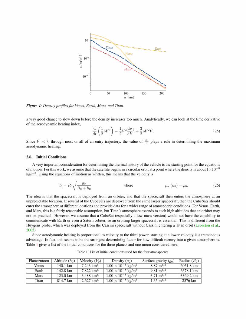
Figures 3 and 4 show the atmospheric temperature and density, respectively, as a function of altitude for the fouratmospheres considered here. The atmospheric data for Venus (Jenkins, 1994; Patzold et al., 2007), Mars (Clancy et al.,1990), and Titan (Flasar et al., 1981; Lindal et al., 1983) come from various remote sensing techniques, and the modelsused for this paper are simplifications of that data.
The densities, shown in Figure 4, are fairly similar at the upper altitudes except for Titan. Comparing the actualvalues at a given altitude is not particularly important for this study because a denser atmosphere would just mean that theCubeSat begins its descent from a higher orbit. For example, a 150 km orbit above Mars is very similar to a 170 km orbitabove Earth. However, the rate at which density decreases with altitude is important. For Venus, Earth, and Venus, anincrease of 100 km in altitude will cause the density to drop by about 10−5 whereas the same altitude increase for Titanwill only cause a decrease between 10−1 and 10−2. As a result, a spacecraft descending through Titan’s atmosphere has
h [km]
ρ ∞[k
g/m
3]
0 50 100 150 200
10−10
10−5
100
Earth
Mars
Venus
Titan
Figure 4: Density profiles for Venus, Earth, Mars, and Titan.
a very good chance to slow down before the density increases too much. Analytically, we can look at the time derivativeof the aerodynamic heating index,
d
dt
(1
2ρV 3
)=
1
2V 3 dρ
dhh+
3
2ρV 2V . (25)
Since V < 0 through most or all of an entry trajectory, the value of dρdh plays a role in determining the maximum
aerodynamic heating.
2.6. Initial Conditions
A very important consideration for determining the thermal history of the vehicle is the starting point for the equationsof motion. For this work, we assume that the satellite begins in a circular orbit at a point where the density is about 1×10⁻⁸kg/m3. Using the equations of motion as written, this means that the velocity is
V0 = R0
√g0
R0 + h0where ρ∞(h0) = ρ0. (26)
The idea is that the spacecraft is deployed from an orbiter, and that the spacecraft then enters the atmosphere at anunpredictable location. If several of the CubeSats are deployed from the same larger spacecraft, then the CubeSats shouldenter the atmosphere at different locations and provide data for a wider range of atmospheric conditions. For Venus, Earth,and Mars, this is a fairly reasonable assumption, but Titan’s atmosphere extends to such high altitudes that an orbiter maynot be practical. However, we assume that a CubeSat (especially a low-mass version) would not have the capability tocommunicate with Earth or even a Saturn orbiter, so an orbiting larger spacecraft is essential. This is different from theHuygens probe, which was deployed from the Cassini spacecraft without Cassini entering a Titan orbit (Lebreton et al.,2005).
Since aerodynamic heating is proportional to velocity to the third power, starting at a lower velocity is a tremendousadvantage. In fact, this seems to be the strongest determining factor for how difficult reentry into a given atmosphere is.Table 1 gives a list of the initial conditions for the three planets and one moon considered here.
Table 1: List of initial conditions used for the four atmospheres.
Planet/moon Altitude (h0) Velocity (V0) Density (ρ0) Surface gravity (g0) Radius (R0)Venus 140.1 km 7.243 km/s 1.00× 10⁻⁸ kg/m3 8.87 m/s2 6051.8 kmEarth 142.8 km 7.822 km/s 1.00× 10⁻⁸ kg/m3 9.81 m/s2 6378.1 kmMars 123.0 km 3.488 km/s 1.00× 10⁻⁸ kg/m3 3.71 m/s2 3369.2 kmTitan 814.7 km 2.627 km/s 1.00× 10⁻⁸ kg/m3 1.35 m/s2 2576 km

3. RESULTSThe purpose of this section is to demonstrate the simulation capabilities and begin to explore the design space for this
type of reentry vehicle. Section 3.1 explores entry into the four available atmospheres. In any case, a very low ballisticcoefficient is required in order to keep the maximum temperature low, and as a result vehicle mass is a key parameter.Investigating the four different atmospheres helps us understand the performance characteristics required for each planetor moon. Furthermore, having a range of reentry trajectories helps validate the assumptions used to create this model.
In section 3.2, we explore the sensitivity of the entry trajectory to mass. Only Titan entry trajectories are considered,since Titan has most favorable atmosphere and gravity to this type of mission. The simulations help to show that thisstrategy for entry is feasible for CubeSat designs that either have very low mass or very large wings, which leads toseveral engineering challenges.
3.1. Sample Entry Trajectories
In this subsection, we consider an entry trajectory into the four atmosphere discussed in Section 2.5 using the samevehicle, which helps to show what aspects of an atmosphere make this type of mission more or less feasible. Table 2 showsthe important design parameters of the vehicle. It trims at an angle of attack around 45◦, which leads to a lift-to-drag ratioof about 1.0, which is similar to vehicles such as the space shuttle and the X-38 (Graesslin et al., 2002). This design isthe result of a minimization of the maximum temperature during Venus reentry. The values in the left column of Table 2were held constant, and the trim angle of attack, α∗ was the design variable. Then a center of gravity location was chosenthat leads to that angle of attack.
Table 2: Design and performance parameters for vehicle.
Design parameters Value Performance parameters Valuemv (total mass) 0.5 kg α∗ (trim angle of attack) 45.2◦
ε (surface emissivity) 0.9 Cq (thermal heating coefficient) 0.184Lx (vehicle length) 30 cm CD (drag coefficient) 0.396
Ly, Lz (vehicle width) 10 cm L/D (lift-to-drag ratio) 0.994xcut/Lx (cut fraction) 0.3 B (ballistic coefficient) 0.53 kg/m2
bwing/Lx (wing span) 5cwing/Lx (wing chord) 0.6
A mass of 0.5 kg was selected as a compromise between the very low masses that make safe reentry more feasibleand the actual values that are required to produce a functioning spacecraft. A typical mass for a 3U CubeSat is about 3 kg(Cutler et al., 2011), which means that a vehicle designed for this type of reentry will have less capability than a typical3U CubeSat.
Figures 5 and 6 show the altitude and temperature history, respectively, for the four reentry trajectories. The initialconditions for each trajectory are given in Table 1. Because the trajectories each take a different amount of time, thex-axis is normalized. In addition, the interesting part of the entry trajectory takes place over a relatively short time period.The reason is that the spacecraft starts in a circular orbit that decays very slowly at first. The x-axis used for the trajectoryplots in this paper is a progress variable based on velocity. Specifically, the progress variable is 1− V
V0. The simulations
are stopped when the velocity is reduced to one eighth of its initial value, which means that the progress variable is 0.125.However, notice that 1 − V
V0can be slightly negative in the beginning of the simulation as the vehicle loses altitude and
gains velocity.The altitude profiles of Figure 5 are not particularly surprising; the spacecraft gains some velocity as its orbital altitude
decreases, and then the velocity and altitude decrease together during the actual entry portion. It is interesting that thealtitude decreases by only 28% for the Venus trajectory while it decreases by 76% for the Titan trajectory. Since a changein altitude above Venus affects the atmospheric density–and thus also the drag force–so much, it is not surprising thatthe spacecraft loses most of its velocity before it has lost too much altitude. However, since Figure 4 shows that Marsand Earth have similar values for the derivative of density with respect to altitude, we need another explanation for thedifference between the Mars and Earth trajectories. The explanation is that the deceleration, as shown in Equation (18),is proportional to the velocity. In particular, V /V0 is proportional to V0, which means that the spacecraft takes more timeto decelerate for a Mars entry trajectory than for an Earth entry trajectory.
The temperature histories of Figure 6 show that of the four simulations, only entry into Titan keeps the vehicle within

0 0.2 0.4 0.6 0.8
0.4
0.5
0.6
0.7
0.8
0.9
1
h / h
0
1 − V / V0
Venus
Earth
Titan
Mars
Figure 5: Altitude profile of reentry trajectories in all four atmospheres for the vehicle.
0 0.2 0.4 0.6 0.8100
200
300
400
500
600
700
800
Tv
[K]
1 − V / V0
Venus
Earth
Titan
Mars
Figure 6: Temperature history along reentry trajectories in all four atmospheres for the vehicle.

a functioning temperature range with this vehicle design. Although it is possible to insulate the functioning parts ofthe satellite from the hot surfaces to some extent, the maximum temperatures are likely too high for a little insulationto be enough. The simulated maximum temperatures could easily be reduced by either decreasing the vehicle mass orincreasing the wing span, but the results with high maximum temperatures are shown here to demonstrate the engineeringdifficulties.
Interestingly, the temperature profiles for Earth and Venus show several wiggles. These basically “skips” in theatmosphere, in which the vehicle gains extra velocity during a descent that generates enough lift to temporarily increasethe flightpath angle. Skips are a common feature for entry from super-orbital speeds (Way et al., 2007), they are somewhatsurprising for a trajectory that starts from a circular orbit. It should be noted however, that the “skips” in these simulationsnever actually increase the flightpath angle above zero, i.e., they never cause the satellite to actually gain altitude.
0 0.2 0.4 0.6 0.8
10−8
10−7
10−6
10−5
10−4
1 − V / V0
ρ [
kg/m
3 ]
Venus
Earth
Titan
Mars
Figure 7: Atmospheric density along reentry trajectories in all four atmospheres for the vehicle.
0 0.2 0.4 0.6 0.810
−2
10−1
100
101
dyna
mic
pre
ssur
e [
Pa]
1 − V / V0
Venus
Earth
Titan
Mars
Figure 8: Dynamic pressure along reentry trajectories in all four atmospheres for the vehicle.
Figures 7, 8, and 9 show several of the atmospheric parameters during the same entry trajectories. The density historyof 7 shows no new information since it only combines values from Figures 4 and 5, but it is interesting nonetheless. One

0 0.2 0.4 0.6 0.810
−2
10−1
100
101
102
1 − V / V0
VenusEarth
Titan
Mars
aero
dyna
mic
hea
ting
inde
x [
W m
−2 ]
Figure 9: Aerodynamic heating index history along reentry trajectories in all four atmospheres for the vehicle.
note is that the density histories for Earth and Venus are almost identical even though the altitude histories are not. Inaddition, the density increases more for Titan than for the other atmospheres even though Titan has by far the lowestdensity gradient.
The plots of dynamic pressure ( 12ρV2) and aerodynamic heating index ( 12ρV
3) in Figures 8 and 9, respectively,combine the density and velocity histories. The dynamic pressure is very important because it shows how strong thewings must be. In this case the maximum dynamic pressure in any of the simulations is 40 Pa. Since the wing area is0.027 m2, this means that the total force on the wings is below 1 N. If all of this force acted at the wing tip, it would exerta torque of 0.75 N m at the root of the wing. The manageable forces make it possible to use very light wings.
Because the vehicle has so little mass, the aerodynamic heating index histories of Figure 9 are almost equivalent to thetemperature histories. It is interesting that the heating index is almost flat throughout the reentry trajectory. As a result, themaximum heating is distributed throughout the trajectory rather than spiking for a short period. It also means, however,that the surface will be at an elevated temperature for an extended period of time.
3.2. Sensitivity to Mass
This subsection further investigates entry trajectories for Titan using the same altitude and velocity initial conditions.The same vehicle described in Table 2 is used except that the mass is varied between 0.2 kg and 1.0 kg. The temperaturehistories for the trajectories are shown in Figure 10, and the most important results are listed in Table 3.
Table 3: Important parameters for the Titan reentry vehicles.
Mass Max Tv Max dynamic pressure Number of orbits Number of days0.2 kg 249.12 K 1.52 Pa 25 4.450.4 kg 297.77 K 3.11 Pa 50 8.720.6 kg 330.75 K 4.73 Pa 75 12.990.8 kg 356.12 K 6.38 Pa 100 17.261.0 kg 377.51 K 8.03 Pa 125 21.53
As expected, the surface temperature is higher for the massive vehicles, which plunge deeper into the atmospherebefore slowing down. It is surprising, though, that the number of full Titan orbits before reentry is apparently directlyproportional to the mass. Much like a satellite in a low-Earth orbit, the spacecraft stays in a slowly decaying, nearlycircular orbit for some period of time. For these simulations, that period of time was between 4 and 22 days, and thenthe actual entry takes less than a single orbit. One result of this is that the vehicle stays at one point in the temperature-

0 0.2 0.4 0.6 0.8
100
150
200
250
300
350
400
Tv
[K]
1 − V / V0
m = 0.2 kg
m = 0.4 kg
m = 0.6 kg
m = 1.0 kgm = 0.8 kg
Figure 10: Temperature history for entry into Titan’s atmosphere with five different vehicle masses.
versus-velocity plot of Figure 10 for most of the time, and then it quickly sweeps out the temperature histories within asingle orbit. This is also interesting because it indicates that two satellites that are released at slightly different times fromthe same parent spacecraft have a good chance to enter Titan’s atmosphere at very different locations.
4. DESIGN ISSUESThis strategy for studying planetary atmospheres comes with numerous engineering challenges. The first and most
obvious is the desire to keep the mass as low as possible while still retaining some function. It is fortunate that there isat least one practical application of this design that does not require too much capability on the part of the CubeSat, butdesigns that allow for more vehicle mass and stay within the thermal constraints would be very useful.
Because the wings play such an important role in this design, it is worth discussing them in more detail. In particular,adding more area to the wings is an obvious way to add more drag and more lift, and thus lower the temperature. However,the wings create at least two obvious design issues: the wings must be deployed somehow, and they must be strong enoughwithout adding much mass to the vehicle. Fortunately, the dynamic pressure is low enough that the wings only have tohold at most one Newton of force. This means that the wings do not have to be very strong at all, and a simple deploymentmechanism can be employed. An example is a thin foil between two telescoping rods. Furthermore, increasing the wingspan will also decrease the maximum dynamic pressure, so that the maximum force on the wing will decrease by a smalleramount than the increase in area. It should be noted that deployables are common on CubeSats, have flight heritage, andthere is continued development in technologies like articulated solar panels
It is conceivable that the instrumentation could be insulated from the hot lift- and drag-producing surfaces of thevehicle. In particular, the wings could be allowed to get very hot if they are thermally isolated from the rest of the vehicle.However, the vertical fins should be in good thermal contact with the rest of the vehicle because they have very littleaerodynamic heating (because they are parallel to the flow), and they serve the second purpose of radiating away heat.
5. CONCLUSIONSThis study introduces a method for a small satellite to reenter planetary atmospheres without a thermal protection
system. The design is based on the dimensions of a 3U CubeSat, but almost any geometry with a high surface-area–to–mass ratio is a good candidate. A set of design variables that parametrizes a generic set of CubeSat-derived vehicles wasconstructed, and a simple model was constructed to test the feasibility of such a design.
Simulations were done for the four large atmospheres of rocky planets or moons in the solar system. The simulationsshow promise for such a reentry vehicle, although the design is not without challenges. A design was identified that thesimulations predict can survive entry into Titan’s atmosphere, and only slight modifications may make Mars entry also

feasible. Furthermore, the most important design parameters were identified, and several engineering challenges werediscussed.
The primary application of such a vehicle design is to study atmospheres of Venus, Mars, and Titan, so it must providebetter data than the best existing techniques in order to be useful. Compared to radio occultation, which has been theprimary source of atmospheric data for Venus, Mars, and Titan, this technique has several advantages. First, since thesatellites are so small, the parent spacecraft can deploy a number of these small satellites in order to gather data fromseveral locations in the atmosphere. Ideally, seasonal or latitudinal variations could be observed. A further advantageis that they can provide better data on the tenuous upper atmosphere. Finally, the possibility of in situ atmosphericmeasurements is introduced.
Before such a satellite could be constructed, a more thorough analysis of the entire spacecraft would be needed.Structural, communication, and instrumentation components would need to be specified that have the smallest masspossible. In total, this is a case of designing a vehicle that acts both as a spacecraft and an airplane (in this case a glider),which causes many conflicting demands of the vehicle. In this paper, we have only discussed the aerodynamic properties,along with a very simplified thermal analysis, and a more complete study may show the concept to be either more or lessfeasible than it appears here.
REFERENCESAilor, W. H., Kapoor, V. B., Allen, Gay A., J., Venkatapathy, E., Arnold, J. O., and Rasky, D. J. (2005): Pico Reentry
Probes: Affordable Options for Reentry Measurements and Testing. 2nd International Planetary Probe Workshop,pp. 291–300. URL http://ntrs.nasa.gov/archive/nasa/casi.ntrs.nasa.gov/20070014612_2007014748.pdf.
Andringa, J. M. (2001): A Systems Study on How to Dispose of Fleets of Small Satellites. Master of science, Departmentof Aeronautics and Astronautics, Massachussetts Institute of Technology. URL http://www.sciencedirect.com/science/article/pii/S0273117710006836.
Anon. (1976): U.S. Standard Atmosphere. U.S. Government Printing Office. Washington, D.C.
Carbon, S. L. and Larson, E. W. F. (2005): Modeling of Risk to Aircraft from Space Vehicle Debris. In AIAA AtmosphericFlight Mechanics Conference and Exhibit. AIAA Paper 2005-6506.
Clancy, R. T., Muhleman, D. O., and Berge, G. L. (1990): Global Changes in the 0-70 km Thermal Structure of the MarsAtmosphere Derived from 1975 to 1989 Microwvave CO Spectra. Journal of Geophysical Research, vol. 95 (B9), pp.14543–14554.
Cutler, J. W., Springmann, J. C., Spangelo, S., and Bahcivan, H. (2011): Initial Flight Asessment of the Radio AuroraExplorer. In Proceedings of the 25th Annual Small Satellite Conference. Logan, UT.
Flasar, F. M., Samuelson, R. E., and Conrath, B. J. (1981): Titan’s atmosphere: temperature and dynamics. Nature, vol.292, pp. 693–698.
Gallais, P. (2007): Atmospheric re-entry vehicle mechanics. Springer.
Gombosi, T. I. (1994): Gaskinetic Theory. Cambridge University Press.
Graesslin, M., Wallner, E., Burkhardt, J., Schoettle, U., and Well, K. H. (2002): Adaptive Guidance and Control Algo-rithms applied to the X-38 Reentry Mission. In 34th COSPAR Scientific Assemply.
Griffith, B. J. and Boyland, D. E. (1968): Reynolds and Mach number simulations of Apollo and Gemini re-entry andcomparisons with flight. In NATO Advisory Group for Aerospace Research and Development. pp. 8–1–8–21.
Groves, P. D. (2008): Principles of GNSS, Inertial, and Multisensor Integrated Navigations Systems. Artec House.
Jenkins, J. M. (1994): Radio Occultation Studies of the Venus Atmosphere with the Magellan Spacecraft. Icarus, vol.110, pp. 79–94.
Koyama, M., Suzuki, K., Imamura, O., and Yamada, K. (2009): Study on Mini Re-Entry System Using DeployableMembrane Aeroshell. Transactions of the Japan Society for Aeronautical and Space Sciences, vol. 7, pp. 25–30.

Lebreton, J.-P., Witasse, O., Sollazzo, C., Blancquaert, T., Couzin, P., Marie Schipper, A., Jones, J. B., Matson, D. L.,Gurvits, L. I., Atkinson, D. H., Kazeminejad, B., and Perez-Ayucar, M. (2005): An overview of the descent and landingof the Huygens probe on Titan. Nature, vol. 438, pp. 758–764.
Lindal, G. F., Wood, G. E., Hotz, H. B., and Sweetnam, D. N. (1983): The atmosphere of Titan: An analysis of theVoyager 1 radio occulation measurements. Icarus, vol. 53 (2), pp. 348–363.
Liou, J. C. (2012): Orbital Debris Modeling. ASA NASA Orbital Debris Program Office Orbital Debris Pro-gram Office, JSC-CN-25941. URL http://ntrs.nasa.gov/archive/nasa/casi.ntrs.nasa.gov/20120003286_2012003361.pdf.
Pardini, C. and Anselmo, L. (2004): On the accuracy of satellite reentry predictions. Advances in Space Research,vol. 34 (5), pp. 1038 – 1043. doi:10.1016/j.asr.2003.01.010. URL http://www.sciencedirect.com/science/article/pii/S0273117704000808.
Patera, D. R. P. and Ailor, D. W. H. (1998): The Realities of Reentry Disposal. Advances in Astronautical Science, AAS 98-174. URL http://www.globalsecurity.org/space/library/report/enviro/reentrypaper.pdf.
Patzold, M., Hausler, B., Bird, M. K., Tellmann, S., Mattei, R., Asmar, S. W., Dehant, V., Eidel, W., Imamura, T.,Simpson, R. A., and Tyler, G. L. (2007): The structure of Venus’ middle atmosphere and ionosphere. Nature, vol. 450,pp. 657–660.
Szewczyk, N. J., Mancinelli, R. L., McLamb, W., Reed, D., Blumberg, B. S., and Conley, C. A. (2005): Caenorhabditiselegans Survives Atmospheric Breakup of STS-107, Space Shuttle Columbia. Astrobiology, vol. 5 (6), pp. 1–16.
Therese, M. J. (2012): CubeSat-based Science Missions for Geospace and Atmospheric Research. National ScienceFoundation, Division of Atmospheric and Geospace Sciences Solicitation 12-536. URL http://www.nsf.gov/funding/pgm_summ.jsp?pims_id=503172.
Way, D. W., Powell, R. W., Chen, A., Steltzner, A. D., Martin, A. M. S., Burkhart, P. D., and Mendeck, G. F. (2007): MarsScience Laboratory: Entry, Descent, and Landing System Performance. In 2007 IEEE Aerospace Conferenc. pp. 1–19.
Wiegand, M. and Knigsmann, H. J. (1996): A Small Re-entry Capsule - BREM-SAT 2r. In Proceedings of the 10thAnnual Small Satellite Conference. Logan, UT.
Woellert, K., Ehrenfreund, P., Ricco, A. J., and Hertzfeld, H. (2011): Cubesats: Cost-effective science and tech-nology platforms for emerging and developing nations. Advances in Space Research, vol. 47 (4), pp. 663 –684. doi:10.1016/j.asr.2010.10.009. URL http://www.sciencedirect.com/science/article/pii/S0273117710006836.