PRELIMINARY DESIGN OF A SOLAR ‘HEAT RECEIVER … · nasa technical memorandum preliminary design...
43
NASA TECHNiCAL MEMORANDUM PRELIMINARY DESIGN OF A SOLAR ‘HEAT RECEIVER FOR A BRAYTON-CYCLE ‘. ,. SPACE POWER SYSTEM - by Hurry M. Cumeron, Lawrence A. Mueller, und David iVm&oo~zg Lewis Research Center Clevelund, Ohio 44135 ,. n#i: NATIONAL AERONAUTICS AND SPACE ADMINISTRATION l WASHINGTON, D. C. . MAY 1972 https://ntrs.nasa.gov/search.jsp?R=19720015404 2018-07-24T01:32:29+00:00Z
Transcript of PRELIMINARY DESIGN OF A SOLAR ‘HEAT RECEIVER … · nasa technical memorandum preliminary design...

NASA TECHNiCAL
MEMORANDUM
PRELIMINARY DESIGN OF A SOLAR ‘HEAT RECEIVER FOR A BRAYTON-CYCLE ‘. ,. SPACE POWER SYSTEM -
by Hurry M. Cumeron, Lawrence A. Mueller,
und David iVm&oo~zg
Lewis Research Center
Clevelund, Ohio 44135 ,. n#i:
NATIONAL AERONAUTICS AND SPACE ADMINISTRATION l WASHINGTON, D. C. . MAY 1972
https://ntrs.nasa.gov/search.jsp?R=19720015404 2018-07-24T01:32:29+00:00Z
I:’ TECH LIBRARY KAFB, NM
llnlllull~llllIlllllllu~llII 1. Report No.
NASA TM X-2552 2. Government Accession No. 3. Recipient’s Catalog No.
4. Title and Subtitle
PRELIMINARY DESIGN OF A SOLAR HEAT RECEIVER FOR A BRAYTON-CYCLE SPACE POWER SYSTEM
5. Report Date
May 1972 6. Performing Organization Code
7. Author(s) 1 6. Performing Organization Report No.
Harry M. Cameron, Lawrence A. Mueller, and David Namkoong
9. Performing Organization Name and Address
Lewis Research Center National Aeronautics and Space Administration Cleveland, Ohio 44135
12. Sponsoring Agency Name and Address
National Aeronautics and Space Administration Washington, D. C. 20546
15. Supplementary Notes
E-6740 10. Work Unit No.
113-34 11. Contract or Grant No.
13. Type of Report and Period Covered
Technical Memorandum 14. Sponsoring Agency Code
16. Abstract
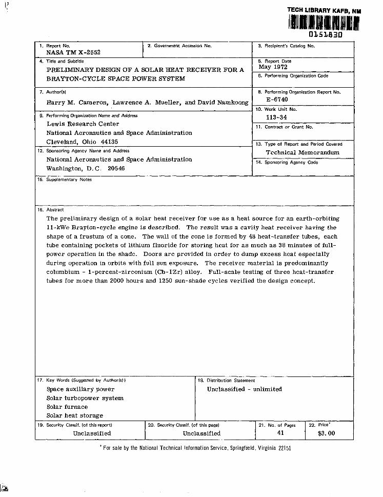
The preliminary design of a solar heat receiver for use as a heat source for an earth-orbiting 11-kWe Brayton-cycle engine is described. The result was a cavity heat receiver having the shape of a frustum of a cone. The wall of the cone is formed by 48 heat-transfer tubes, each tube containing pockets of lithium fluoride for storing heat for as much as 38 minutes of full- power operation in the shade. Doors are provided in order to dump excess heat especially during operation in orbits with full sun exposure. The receiver material is predominantly columbium - l-percent-zirconium (Cb-1Zr) alloy. Full-scale testing of three heat-transfer tubes for more than 2000 hours and 1250 sun-shade cycles verified the design concept.
17. Key Words (Suggested by Author(s) I
Space auxiliary power Solar turbopower system Solar furnace Solar heat storage
)
I
19. Security Clanif. (of this report) 20. Security Classif. (of this page) 21. No. of Pages
Unclassified Unclassified 41
* For sale by the National Technical Information Service, Springfield, Virginia 22151
22. Price*
$3.00

PRELIMINARY DESIGN OFA SOLAR HEAT RECEIVER FOR A BRAYTON-CYCLE SPACE POWER SYSTEM
by HarryM. Cameron, Lawrence A. Mueller, and David Namkoong Lewis Research Center
SUMMARY
Solar radiation is one of the heat sources which has been considered for a Brayton- cycle engine designed for providing onboard electric power for earth-orbiting spacecraft. The heat receiver accepts the solar rays from a g-meter- (30-ft-) diameter parabolic mirror and transfers the resulting thermal energy to the Brayton-cycle working fluid, a mixture of helium and xenon. In low earth orbit, the required collector area is one- third the area of solar cells for comparable electric power output.
The cavity-type heat receiver incorporates a heat-storage capability by making use of the latent heat of fusion of lithium fluoride (LiF). This enables the Brayton-cycle engine to operate at full power for shade periods as long as 38 minutes, which is ade- quate for earth orbital altitudes between 180 and 5600 kilometers (100 and 3000 n mi).
The shape of the cavity was determined on the basis of matching the solar flux dis- tribution on the cavity walls to the local heat-transfer rates. The resulting wall was a frustum of a cone formed by 48 tube assemblies and terminated by torus-shaped inlet and outlet manifolds.
Each tube assembly was designed to contain the heat-storage medium. A number of concepts for this containment were investigated to accommodate the large volume ex- pansion experienced by LiF in changing from the solid to the liquid state. The resulting design was a convoluted tube in which the convolutions serve as fluoride storage cells.
An aperture and an aperture cone form one side of the cavity. The aperture size was selected to maximize the net energy input through the aperture. This resulted in the selection of a 20-centimeter (8-in. ) aperture diameter for use in space. The aper- ture cone also incorporates heat-rejection doors for discarding excess heat.
The material chosen for the heat receiver construction was columbium - l-percent zirconium (Cb-1Zr) because of the combination of its excellent properties of long-term high-temperature strength, elastic modulus, coefficient of thermal expansion, and thermal conductivity.
To confirm the design of the heat-transfer tubes, three tubes were tested under conditions simulating those they would experience within the receiver. Endurance test- ing covered 2000 hours and 1250 sun-shade cycles. The tubes retained their mechanical integrity; no cracks or LiF leaks were detected. The convoluted-tube concept used for maintaining the desired distribution of LiF along the tube length, as well as the adequacy of the heat-transfer characteristics, was demonstrated.

INTRODUCTION
The utilization of solar energy is one means of providing space vehicles with on- board auxiliary electric power. This energy could be harnessed by direct conversion, that is, solar cells, or by means of a heat engine. For the latter, the solar flux in near-earth orbits, approximately 1400 W/m2 (440 Btu/(hr)(ft2)), must be concentrated to achieve the temperatures which result in efficient engine operation. To effect con- centration, the solar rays could be collected by a parabolic mirror, hereinafter re- ferred to as a collector, and focused onto a receiving surface. The receiving surface would function as the heat source for the heat engine, transferring the solar energy to the engine working fluid.
The solar heat receiver provides a cavity into which the solar rays are reflected by the collector. The solar energy enters the cavity through a small aperture at the col- lector’s focus and impinges on the cavity walls. The cavity walls consist of individual tubes, which serve both to transfer energy to the Brayton-cycle working gas and to store sufficient heat to allow full-power operation in the shade. The receiver, as designed, is capable of transferring 40 kilowatts of thermal energy to the Brayton-cycle gas dur- ing both the sun and shade portions of an earth orbit. The geometry and performance are described in more detail in later sections.
The heat-storage function of the receiver was a major problem in the design. The large energy-storage requirements make it d.esirable to utilize the heat of fusion of a storage material. Because candidate heat-storage materials experience large volume changes during their phase change (lithium fluoride (LiF) is used as a storage material in the solar receiver), these volume changes must be accommodated reliably. This re- sulted in a geometric complexity which made an exact analysis of thermal distributions, thermal stresses, and performance impractical. The receiver was therefore designed to be ground tested in a vacuum environment using a solar simulator and a full-scale g-meter- (30-ft-) diameter parabolic collector. It was structurally designed on the basis of launch and space worthiness without necessarily being optimized for weight. To confirm the basic design of the heat-storage tubes, a test was conducted on three tubes under conditions simulating, except for gravity, an orbital mission. A description of this test and its results are included herein and more fully in reference 1.
Previous work on heat receivers with LiF heat storage has been reported in refer- ences 2 and 3. One design was a hemispherical-cavity heat receiver that lacked pro- visions for maintaining uniform LiF distribution (under earth test conditions). The second was a cylindrical-cavity heat receiver that provided for LiF containment by en- trapment in metal felt; tests determined that the metal felt resulted in poor heat trans- fer, and baffled containment was recommended instead of the metal felt. This recom- mendation is reflected in the design used herein.
2

The purpose of this report is to describe the design of the solar heat receiver. It was designed as one possible heat source for a closed-loop Brayton-cycle engine that is being investigated at Lewis Research Center (refs. 4 and 5).
Based on the described design concept, 48 heat-transfer tubes were fabricated at Lewis Research Center and filled at Oak Ridge National Laboratory. The detailed design and fabrication of a complete solar receiver using these 48 tubes was completed at the General Electric Company.
BRAYTON-CYCLE DESCRIPTION
The Brayton engine is designed to provide onboard electric power to spacecraft for housekeeping and experimental requirements. The powerplant incorporates two loops. The primary loop includes the heat source; the Brayton Rotating Unit (BRU), an assem- bly of the turbine, compressor, and alternator; and a combined recuperator and heat- sink heat exchanger. A mixture of helium (He) and xenon (Xe) with the molecular weight of 83. 8 serves as the working fluid. The secondary loop includes the radiator and shares the heat-sink heat exchanger with the primary loop. A schematic depicting the system parameters for a nominal ll-kilowatt-electric design output using a solar heat source is shown in figure 1. A more complete description of the Brayton cycle is given in references 4 and 5.
The solar heat source consists of the parabolic collector and the solar heat receiver. When the collector axis is alined with the sun axis, approximately ‘78 kilowatts of thermal energy is delivered to the receiver, of which approximately 40 kilowatts is continually transferred to the working fluid. The working fluid, heated to 1089 K (1960’ R), drives the turbine, flows through the recuperator to effect a heat exchange with the compressor effluent, flows through the heat-sink heat exchanger, and is then recompressed to its maximum system pressure. The waste heat is transferred from the heat-sink heat ex- changer to the radiator. Of the remaining solar energy inputs, about 30 kilowatt-hours can be stored as heat of fusion of the LiF. The balance is lost by radiation through the aperture and from the insulation surrounding the heat receiver. A heat balance for the heat receiver is given in table I.
One of the major constraints on any solar power system is the length of shade time a system is able to tolerate while maintaining full power. This time is dependent on the quantity of storage material per energy consumption rate of the heat engine. The use- fulness of a space power system is enhanced if its application is flexible with respect to missions requiring different orbits. It is instructive, therefore, to know the range of applicability of a system with a fixed mass of storage material.

TABLE I. - HEAT BALANCE FOR SOLAR BRAYTON HEAT RECEIVER IN
98-MINUTE ORBIT (60 MIN SUN, 38 MIN SHADE)
Solar flux at 1 A. U. in g-meter (30-ft) circle, J (Btu) . . . . . . . . . . . . . . . . . . . . 329x108 (312 000) Losses due to mirror inefficiency and shadowing, J (Btu) . . . . . . . . . . . . . . . . . . 0. 44x108 (42 000) Available solar input, J (Btu) . . . . . . . . . . . . . . . . . . . . . . . . . . . . . . . . 2.85~10~ (2’70 000) Input to working fluid, J (Btu):
Sun period . . . . . . . . . . . . . . . . . . . . . . . . . . . . . . . . . . . . . . . . . 1. 45x108 (138 000) Shade period . . . . . . . . . . . . . . . . . . . . . . . . . . . . . . . . . . . . _ . . . 0. 928x108 (87 000) Total . . . . . . . . . . . . . . . . . . . . . . . . . . . . . . . . . . . . . . . . . . . . 2.36~10~ (225 000)
Losses, J (Btu): Aperture reradiation:
Sun . . . . . . . . . . . . . . . . . . . . . . . . . . . . . . . . . . . . . . . . . . . . 1.06~10~ (10 000) Shade . . . . . . . . . . . . . . . . . . . . . . . . . . . . . . . . . . . . . . . . . . . . . 0.66~10~ (6300)
Insulation: Sun . . . . . . . . . . . . . . . . . . . . . . . . . . . . . . . . . . . . . . . _ . . . . . 1.85~10~ (17 600) Shade . . . . . . . . . . . . . . . . . . . . . . . . . . . . . . . . . . . . . . _ . . . . . . 1.17~10~ (11 100)
Total . . . . . . . . . . . . . . . . . . . . . . . . . . . . . . . . . . . . . . . . . . . . 0. 49x108 (45 000) Required heat input to receiver per orbit, J (Btu) . . . . . . . . . . . . . . . . . . . . . 2.85~10~ (270 000) Heat storage requirements, J (Btu):
Shade period input to working fluid . . . . . . . . . . . . . . . _ . . . . . . . . . _ . . . 9.28~10~ (87 000) Shade period aperture losses . . . . . . . . . . . . . . . . . . . . . . . . . . . . . . . . 0.66~10~ (6300) Shade period insulation losses . . . . . . . . . . . . . . . . . . . . . . . . . . . . . . . 1. 17~10~ (11 100) Total . . . . . . . . . . . . . . . . . . . . . . . . . . . . . . . . . . . . . . . . . . . . 1. 102x108 (104 400)
Figure 2 (ref. 6) shows that for orbits between 180 and 5600 kilometers (100 and 3000 n mi) the shade period remains nearly constant, allowing a single heat-storage system for this entire range of orbits. Sufficient heat-storage material (LiF) is included in the solar receiver to allow it to operate at full power for a shade period (maximum 38 min) corresponding to this range of orbital altitudes. Figure 2 also shows sun time as a function of orbit altitude. Sun time is seen to increase with higher-altitude orbits. Consequently, for such orbits the size of the collector must be reduced, or some of the energy must be rejected to space to prevent overheating and exceeding design tempera- tures. Means for heat rejection (doors) have been incorporated in the receiver design. The g-meter- (30-ft-) diameter collector will satisfy energy input requirements for or- bits as low as 560 kilometers (300 n mi). For lower orbits the collector area would have to be increased to satisfy shade operation at full power.
It is of interest to compare the collector and energy storage requirements of the Brayton system with one utilizing solar cells and batteries for a space electric power supply. A silicon solar cell and nickel-cadmium battery system would require a collec- tor area of 210 square meters (2261 ft2) of solar cells, against the 65.6 square meters (706 ft2) of the Brayton collector, and would have batteries weighing 1580 kilograms
4
(3500 lb) compared with 113 kilograms (250 lb) of LiF and estimated LiF containment of 136 kilograms (300 lb). This comparison is based on the 60-minute - 38-minute sun- shade cycle, an ll-kilowatt-electric power output, a specific solar array output of 107 W/m2 (10 W/ft2), a battery charge-discharge efficiency of 60 percent, and a specific battery weight of 1. 1 kilogram per watt hour (l/2 lb/W-hr). From this comparison the Brayton solar power system appears to be very competitively advantageous for electric power generation in low earth orbits.
RECEIVER DESIGN
Design Objective
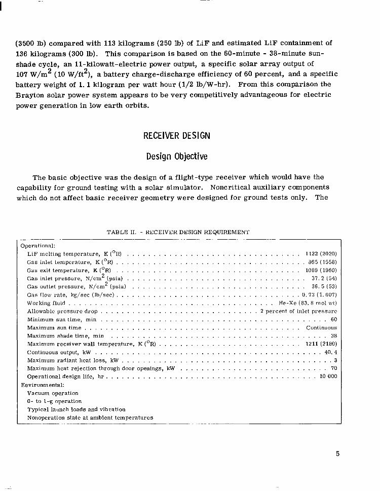
The basic objective was the design of a flight-type receiver which would have the capability for ground testing with a solar simulator. Noncritical auxiliary components which do not affect basic receiver geometry were designed for ground tests only. The
TABLE II. - RECEIVER DESIGN REQUIREMENT _-. Operational:
LiF melting temperature, K (OR) ................................. 1122 (2020) Gas inlet temperature, K (OR) .................................... 865 (1558) Gas exit temperature, K (OR) ................................... 1089 (1960) Gas inlet pressure, N/cm2 (psia) .................................. 37.2 (54) Gas outlet pressure, N/cm2 (psia) ................................. 36. 5 (53) Gas flow rate, kg/set (lb/set) ................................... 0.73 (1.607) Working fluid ....................................... He-Xe (83.8 mol wt) Allowable pressure drop .............................. 2 percent of inlet pressure Minimum sun time, min ........................................... 60 Maximum sun time ......................................... Continuous Maximum shade time, min ......................................... 38 Maximum receiver wall temperature, K (OR) ........................... 1211 (2180) Continuous output, kW ........................................... 40.4 Maximum radiant heat loss, kW ........................................ 3 Maximum heat rejection through door openings, kW ............................ 70 Operational design life, hr ........................................ 10 000
Environmental: Vacuum operation 0- to l-g operation Typical launch loads and vibration Nonoperation state at ambient temperatures
___ ---.--___~
5
I -:
-
design requirements are given in table II. An explanation of some design requirements is in order:
(1) The capability to operate in a normal- and zero-gravity condition (ground test and space operation) is mostly relevant to the control of the LiF freezing pattern.
(2) Since there is no practical possibility of launching the solar Brayton system in an operational state, the structure needs only to be designed to withstand launch loads at earth ambient conditions.
(3) The 10 OOO-hour design life may not appear to be a severe requirement for a component functioning in vacuum; however, there is concern here with low-cycle fatigue of the material due to the thermal expansion and contractions as the receiver tempera- ture cycles between 1172 K (2110’ R) in the sun and 1122 K (2020’ RI in the shade.
Basic Geometry
The basic configuration of the solar receiver is that of a cavity with a small aper- ture. It was shown by McClelland and Stephens (ref. 7) that a cavity closely approaches blackbody radiation conditions when the aperture- to cavity-surface-area ratio is below 0.03 and the emissivity of the cavity surface is above 0.3. Both of these conditions are readily fulfilled in any practical design and have been met in the Brayton-cycle receiver de sign. The absorption efficiency is, therefore, not strongly influenced by cavity shape and is thereby free to be determined predominantly by the requirements of the heat ex- changer.
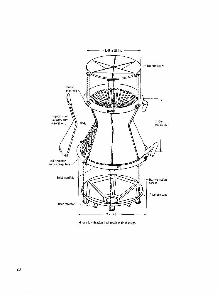
A thermal design objective of the solar receiver is to minimize the time variation in receiver temperatures and in the outlet gas temperatures throughout the sun-shade cycles of an earth orbit. In order to minimize time variations in temperature, it is desirable to maintain the LiF within the boundaries of the two-phase condition to take advantage of its relatively large effective heat capacity during phase change. To accomplish this the radiant heat-input and heat-extraction rates must be matched on a local as well as on a gross basis, and the physical distribution of LiF must be proportional to the local energy storage requirements. The receiver cavity shape, a frustum of a cone, was chosen to meet these constraints. Figure 3 shows the general configuration of the receiver.
The conical shape is achieved by an assembly of 48 heat- exchanger tubes forming 48 parallel flow paths between an inlet and an exit manifold. Each tube incorporates its own heat storage (as described in a later section). A conical outer shell surrounds the tube bundle and is insulated on the exterior side. Reflectors are attached to the inside of the shell in a manner to redirect radiation falling between the tubes onto the back sur- face of the tubes. The tube assembly represents the flux cone on which the direct solar radiation is incident.
6

The base of the flux cone is closed off by the aperture cone attached to the inlet manifold. It contains a central circular opening optimized to admit radiation reflected from the solar collector without allowing excessive reradiation losses to occur. The aperture diameter chosen for space operation was 20 centimeters (8 in. ) and is discussed in appendix A.
The aperture cone design contains six heat-rejection doors, which serve a dual pur- pose. They provide a trimming function for orbits with sun periods longer than 60 min- utes by being capable of opening several degrees to allow excess energy to be reradiated after the LiF heat-storage material is fully melted. The doors can fully open in the event the power conversion system is shut down; this would necessitate that all incoming energy be rejected and receiver temperatures be held at or below design values. The door control system with feedback will be designed to permit proportional control of the cavity temperature through manipulation of door positions from fully closed to fully open. All doors are designed to operate simultaneously to avoid temperature maldistribution within the receiver.
Receiver Cavity Heat-Transfer Distribution
As explained previously, the solar receiver cavity shape was chosen to approach isothermal conditions for the nominal operating conditions in table II. This requires that the distributions of input solar flux and energy extraction by the working gas plus heat- storage requirements be balanced on a local as well as an overall basis. For an iso- thermal heat-transfer surface, the heat flux extracted by the working gas varies expo- nentially along the flow length. The conical cavity shape, as shown in figure 4, was chosen because it yields a distribution of incident solar flux which reasonably matches the distribution of energy extraction.
The distribution of solar flux incident on the receiver cavity wall is calculated as shown in appendix A. The solar radiation is reflected into the receiver as shown in fig- ure 5. The distribution of incident flux is not uniform on the receiver wall because the area ratios of the collector-to-receiver surface vary between the rim of the collector and the central section and because the angle of incidence, as well as the distance from the focal point, changes. Figure 6 gives a plot of incident flux on the conical receiver wall. The receiver wall is considered to be the surface of a hypothetical cone whose elements are the centerline of the gas tubes. Curve 1 in figure 6 plots the solar input as a function of position along the slant height in units of watts per centimeter (Btu/ (hr)(in. )) of slant surface. Curve 2 represents a similar input from a solar simulator from which the rays form a cone angle of 0.046 radian (2’40’). Such a simulator would typically be used in ground testing of the solar receiver. Curve 3 plots the rate of heat
7

extraction by the working fluid as it travels from the inlet to the exit manifold, assuming that the gas tubes (which are described in a later section) are at a constant and uniform temperature of 1120 K (1560’ F), the LiF phase change temperature. If the receiver cavity wall has a solar absorptivity of unity, the difference between curves 1 (or 2) and 3 would constitute the heat-storage rate in the LiF and the heat-loss rate during the sun period. If the LiF is to remain in the two-phase condition (substantially isothermal), the heat stored in it during a sun period must locally equal the sum of heat extracted by the working gas and the heat losses during the following shade period.
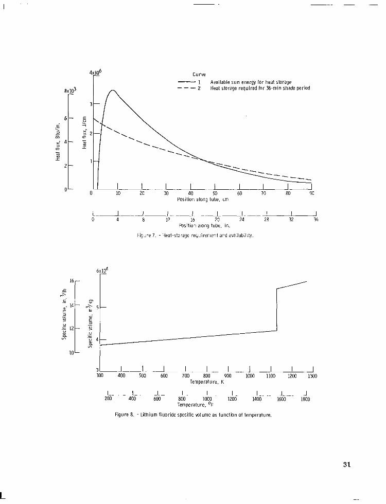
As an indication of the balance between distributions of energy storage during a sun period and energy extraction during a shade period, assume that the solar absorptance of the cavity wall is unity and consider a 60-minute sun period - 38-minute shade period orbit. The difference between curves 1 and 3 in figure 6, integrated over the sun period, is given by curve 1 of figure 7. Curve 2 in figure 7 is the distribution of energy required for heat extraction by the working gas during a 38-minute shade period with the engine operating at full power. If there were no heat losses, curve 1 would be the energy stor-
_ age available for the shade period requirements, and curve 2 would be the shade period requirements. It can be observed that there is a mismatch between these curves which would result in a temperature gradient along the tubes. The radiative exchange within the cavity would modify the input energy distribution to reduce the temperature varia- tions. Actually, the receiver surface will not have a solar absorptance of unity, and re- flection of the incident solar flux will modify the input flux. Also the losses of heat through the insulation and by radiation through the aperture will further modify the dis- tributions of the curves in figure 7. An analytical prediction of these heat-transfer dis- tributions and the resulting temperature variations of the tubes was made in reference 8. This analysis included the effects of reflections of solar energy and radiative exchange within the cavity, heat losses, and variations in sun-shade periods. The results of that’ analysis and the results of the test of three tubes (described in a later section) indicate that the peak hot-spot temperature in the cavity will be below 1190 K (1680’ F).
Heat-Transfer Tubes
The term heat-transfer tube as used in this section refers to the 48 tubes extending from the inlet manifold to the discharge manifold. Each tube actually consists of two tubes - a gas tube through which the working fluid flows, and a concentric, convoluted tube with the heat-storage material (LiF) confined in the annular space between the tubes. To satisfy the conditions of the reference cycle (fig. l), each of the heat-transfer tubes is designed to supply 842 watts (2875 Btu/hr) continuously to the working fluid and must store 2. 29x106 joules (2175 Btu) during the sun period.
8

The gas tube geometry was initially determined when the entire Brayton system was being designed on the basis of argon (Ar) being the working fluid. Subsequently, a re- iteration of the Brayton system optimization resulted in a change of the working fluid to a He-Xe gas mixture. A full discussion of the factors involved in the initial gas tube design and the modifications resulting from the change of the working fluid are included in the following subsection.
These modifications on the gas tube were all essentially internal to the gas tube; therefore, the heat-storage system, located externally to the gas tube, remained un- changed throughout this period of redesign.
Gas tube. ~- - The design of the gas tube geometry was based upon the required heat transfer to, and the allowable pressure drop of, the original Brayton system working fluid - argon. In addition, the physical constraints and incident flux distribution asso- ciated with the conical receiver configuration had to be considered. Within this frame- work, calculations were performed to obtain tube diameter, number of tubes, tube length, and fin design. The tube through which the gas was to flow was assumed to be of uniform temperature throughout its length and at a constant value of 1120 K (1560’ F).
The results indicated that the requirements would be met by using 48 tubes with each tube having an inner diameter of 3.05 centimeters (1. 20 in. ), an active heat- transfer length of 91. 4 centimeters (36 in. ), and an interrupted six-fin design. Tests conducted on an internally finned tube with the same physical measurements as that de- signed (ref. 9) have confirmed the calculated results.
When the working fluid was changed from Ar to He-Xe, the 3. Oti-centimeter- (1.20-in. -) diameter Cb-1Zr gas tubes were already fabricated. The question then to be decided was whether this gas tube could be modified to accept the He-Xe with its higher thermal conductivity. With a resulting higher gas-side coefficient, it was apparent that any internal finning would transfer heat at too high a rate. Of the many designs pro- posed to adjust gas-side heat transfer, the ring-dimple design was chosen. This choice had the advantage of enhancing heat transfer without the use of inserts.
For He-Xe flowing through a gas tube with an inside diameter of 3.05 centimeters (1.20 in. ) and an effective length of 91.4 centimeters (36 in. ), the required heat-transfer coefficient was
h= Q = 86. 3 W/(m2)(K); 15. 2 Btu/(hr)(ft2)(‘R) A( LMTD)
The heat-transfer coefficient for turbulent flow in a smooth tube calculated from the relation Nu = O.O23(Re)” 8(Pr) ‘I3 was
h = 46.0 W/(m2)(K); 8. 10 Btu/(hr)(ft2)(‘R)
9

The intent of the ring-dimple design is to disturb the boundary layer, hence the term “turbulator” to describe this effect, and thereby to increase the gas-side convective coefficient. In this case, the turbulators were to provide an increase by a factor of 1.9 over the coefficient of a smooth tube. With the work by Nunner (ref. 10) as a basis, heat-transfer tests were conducted to ascertain the groove depth required to obtain the design heat-transfer coefficient.
The results, as reported in reference 1, indicated the required groove depth from a heat-transfer consideration to be 0. 124 centimeter (0.049 in. ). The frictional pres- sure drop in the tube was too small to be adequately measured in the tests related to groove sizes. Results of the three-tube test (discussed in a separate section) showed the pressure drop did not exceed 1 inch of water (248 N/m2, or 0.036 psi), including not only friction but also the momentum effect. Indeed, this value is low to such an extent that small pressure drop differences among the tubes can cause a severe mal- distribution of flow. To equalize flow, an orifice was added at the inlet of each receiver tube to increase the pressure drop uniformly but within the allowable limit.
Heat-storage tube. - Lithium fluoride was chosen from among candidate heat- storage materials because of its high heat of fusion (1046 J/g, or 450 Btu/lb) and be- cause its melting point is at a temperature which results in turbine inlet temperatures compatible ;::ith turbine materials for long exposure periods.
As can be seen by inspection of figure 8 (ref. 2), the specific volume of LiF experi- ences about a 30 percent increase during the melting process in addition to an expansion of 12 percent of the solid LiF from room temperature to the melting point. The contain- ment of LiF must therefore be designed to permit this expansion to take place without damage to the containment vessel. This can be accomplished if the void volume created in an initially filled container is distributed throughout the frozen mass with some degree of uniformity. The local encapsulation of small quantities of LiF represents one solution to the problem. Another is to exercise control over the freeze pattern in a volume of LiF integrated with the gas tube. The principal methods of containment which were con- sidered are shown in figure 9.
The concept shown in figure 9(a) utilizes individual modules filled before being as- sembled with the gas tube. Precast solid LiF doughnuts would be inserted into the mod- ules. They would be closed and welded to the tube by electron beam welding. The prin- cipal drawback of this concept is that it would be difficult to establish good contact be- between the module and the tube and this would result in poor heat transfer to and from the LiF.
In figure 9(b) individual modules are shown welded to the gas tube prior to filling. The gas tube also serves as the inner wall of the module. While overcoming the disad- vantages of the precast-LiF concept, it would require the individual filling of a large number of modules (perhaps 500) in a vacuum chamber with both the LiF and the assem-
10
bly being heated to above the receiver operating temperature. Figure 9(c) shows the LiF contained in the annulus between the gas tube and an outer
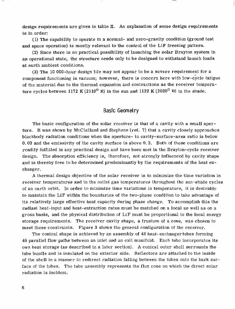
tube. The annulus is compartmentalized in the axial direction by conically shaped spacers brazed to the inner surface of the outer tube, but having small clearances to the gas tube. This design allows filling of an entire tube module because the compart- ments are in communication through the clearance space, which would reduce the number of fillings required to 48. The intent of this design is the control of the freeze pattern to obtain a distribution of the LiF and its void volume among all the compartments during freezing. It works in the following manner: At some initial time the tube will be com- pletely filled with liquid LiF. When the energy input ceases, as will be the case when the sun is eclipsed by the earth, the working fluid will continue to extract heat. The LiF volume residing in the clearance space will tend to freeze first, effecting a freeze seal between the compartment and trapping the volume of LiF in each compartment. The controlled compartmentalization promotes the continued heat transfer over the entire tube surface and ensures the required void volume in each of the compartments.
Because this design (fig. 9(c)) would require a brazed assembly, it too was re- j ected. However, the basic principle was employed in the final design configuration adopted, shown in figure 10. The design of the heat-transfer tube consists of a bellows- shaped shell surrounding the gas tube. The bellows-shaped heat-storage tube is welded to the gas tube at both ends. A diametral clearance of 0.0’76 centimeter (0.030 in. ) exists between the roots of the convolutions and the gas tube, where the freeze seal is effected. Experimental results from the three-tube test confirm that the anticipated LiF
TABLE III. - HEAT-TRANSFER-TUBE ASSEMBLY SPECIFICATIONS
Heat storage tube: Number of convolutions . . . . . . . . . . . . . . . . . . . . . . . . . . . . . . . . . . . _ . . . 37 Convolution diameter, cm (in. ) . . . . . . . . . . . . . . . . . . . . . . . 8.4 (3s) decreasing to 5. 2 (2&) Ccmdution width, cm (in.) . . . . . . . . . . . . . . . . . . . . . . . . . . . . . . . . . . . . . 1.4 (g/16) Convolution pitch, cm (in.) . . . . . . . . . . . . . . . . . . . . . . . . . . . . . . . . . . . . 2. 54 (1) Wall thickness, cm (in.) . . . . . . . . . . . . . . . . . . . . . . . . . . . . . . . . . . . . . 0.89 (0.035)
Gas tube: Diameter of gas passage, cm (in. ) . . . . . . . . . . . . . . . . _ . . . . . . . . . . . . . . . . 3. o (I. 2) Turbulator groove depth, cm (in. ) . . . . . . _ _ . . . . . . . . . . . . . . . . . . . . . . 0. 124 (0.049) Turbulator groove pitch, cm (in. ) . . . . . . . . . . . . . . . . . . . . . . . . . . . . . . . . . . 2. 54 (1) Tube wall thickness, cm (in.). . . . . . . . . . . . . . . . . . . . . . . . . . . . . . . . . . 0. 064 (0.025)
Assembly: Active length, m (in.) . . . . . . . . . . . . . . . . . . . . . . . . . . . . . . . . . . . . . _ . . 0.914 (36) LiF content, kg (lb) . . . . . . . . . . . . . . . . . . . . . . . . . . . . . . . . . . . . . . . . . . 2.4 (5.4) Latent heat capacity, J (Btu) . . . . . . . . . . . . . . . . . . . . . . . . . . . . . . . . . 2. 57~10~ (2430)
Total weight per tube assembly, kg (lb) . . . . . . . . . . . . . . . . . . . . . . . . . . . . . . . . . 5.0 (11) Material . . . . . . . _ . . . . . . . . . . . . . . . . . . . . . . . . . . . . . . . . . . . . . . . . . . Cb-IZr
11
_. __.___ ---~.
freeze pattern can be maintained to a large degree during shade operation. The pertinent design data for the heat-transfer tube are given in table III. The con-
volution size decreases from the inlet end to the exit end in stepped fashion in accordance with the heat-storage requirements indicated in figure 7. The assembly is filled with LiF through a 0.32-centimeter- (0. 125-in. -) inside-diameter tube welded to the convo- luted bellows assembly. After the assembly has cooled, the fill tube is closed off by an electron beam weld. A detailed procedure of the filling process is described in refer- ence 11. Figure 11 shows two X-rays of a section of a filled tube assembly, taken 90’ from each other. The light area is filled with LiF, dark areas are void. The distribu-
tion of voids is clearly seen to fulfill the required freeze pattern control. In the molten stage, at the filling temperature of 1228 K (1750’ F), the LiF occupies the entire con- volution volume. ,
MATERIALS
Columbium - l-Percent Zirconium
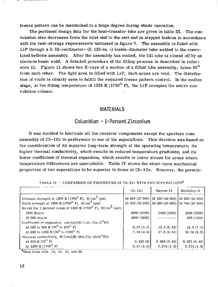
It was decided to fabricate all the receiver components except the aperture cone assembly of Cb-1Zr in preference to one of the superalloys. This decision was based on the consideration of its superior long-term strength at the operating temperature; its higher thermal conductivity, which results in reduced temperature gradients; and its lower coefficient of thermal expansion, which results in lower stress for areas where temperature differences are unavoidable. Table IV shows the short-term mechanical properties of two superalloys to be superior to those of Cb-1Zr. However, the permis-
TABLE IV. - COMPARISON OF PROPERTIES OF Cb-1Zr WITH TWO SUPERALLOYSa
Ultimate strength at 1200 K (1700’ F), N/cm2 (psi) Yield strength at 1200 K (1700’ F), N/cm2 (psi) Stress for 1 percent creep at 1200 K (1700’ F), N/cm2 (psi):
1000 Hours 10 000 Hours
Coefficient of expansion, wm/(m)(K) (pin. /(in. )(‘F)): At 300 to 365 K (70’ to 200’ F) At 300 to 1200 K (70’ to 1700’ F)
Thermal conductivity, W/(cm)(K) (Btu/(in.)(hr)(‘F)): At 294 K (70’ F) At 1200 K (1700’ F)
aData from refs. 14, 18, 19, and 20.
Cb-1Zr
18 600 (27 000) 13 700 (20 000)
6000 (8700) 4000 (5800)
6. 85 (3. 8) 7.94 (4.4)
0.435 (2) 0.61 (2.8)
I Haynes 25
16 200 (38 000) 19 300 (28 000)
2400 (3500) ---------_
12. 3 (6. 83) 17.0 (9.41)
0.098 (0. 45) 0.274 (1. 3)
Hastalloy-X
.9 300 (28 000)
.3 790 (20 000)
1500 (2200) 895 (1300)
13. 8 (7. 7) 16. 56 (9.2)
0.097 (0. 43) 0. 274 (1. 3)
12

sible stress levels for l-percent creep in 1000 and 10 000 hours are about four times higher for Cb-1Zr than for the superalloys; its thermal conductivity is about twice as great; and its coefficient of thermal expansion is only about 50 percent that of the super- alloys.
Cb-1Zr has good formability and machinability characteristics (except for grinding). However, all welding must be performed either in a vacuum or in a high-purity He or Ar atmosphere since the material embrittles seriously with oxygen and nitrogen contam- ination. It also forms brittle intermetallic compounds with many metals. For that rea- son direct contact between Cb-1Zr and other metals should be avoided at elevated tem- peratures. When such contact is unavoidable, junctions must be designed for low stress by utilizing special techniques that have been developed for that purpose.
Lithium Fluoride
Lithium fluoride, the heat storage material chosen for the Bray-ton heat receiver is a stable compound extensively used in industry as flux for welding, brazing, and enamel- ing. In pure single-crystal form it has found application in optics, that is, as a window for ultraviolet transmission.
Its choice from among a number of other materials having a high latent heat of fu- sion (lithium hydride (LiH) and sodium fluoride (NaF)) was based on its melting temper- ature of 1120 K (1560’ F). The lower melting temperature of 950 K (1250’ F) for LiH would result in a lower and less efficient turbine inlet temperature, whereas the melting temperature of 1280 K (1850’ F) for NaF would pose a turbine materials problem.
Five-thousand-hour corrosion tests show that highly purified LiF will not attack Cb-1Zr at the temperatures of interest (ref. 12). The pertinent properties of LiF are listed in table V.
TABLE V. - PROPERTIES OF LITHIUM FLUORIDE
Melting point, K (OR) . . . . . . . . . . . . . . . . . . . . . . . . . . . . . . . . . . . . . . . . 1122 (2020) Heat of fusion, J/g (Btu/lb) . . . . . . . . . . . . . . . . . . . . . . . . . . . . . . . . . . . . . . Density, kg/m3 (lb/ft3):
i
1046 (450)
At room temperature . . . . . . . . . . . . . . . . . . . . . . . . . . . . . . . . . . . 2. 6295x103 (0.095) Solid at 1178 K (2020’ R) . . . . . . . . . . . . . . . . . . . . . . . . . . . . . . . . . 2.3251~10~ (0.084) Liquid at 1178 K (2020’ R) . . . . . . . . . . . . . . . . . . . . . . . . . . . . . . . . 1. 7991x103 (0.065) Liquid at 1256 K (2260’ R) . . . . . . . . . . . . . . . . . . . . . . . . . . . . . . . . 1. 7715x103 (0.064)
Thermal conductivity, W/(m)(K) (Btu/(hr)(ft)(‘R)): Liquid . . . . . . . . . . . . . . . . . . . . . . . . . . . . . . . . . . . . . . . . . . . . . . . . . . 19 (11) So~d.................................................. 8. 68 (5)
Specific heat, J/(g)(K) (Btu/(lb)(ft)(‘R)): Liquid . . . . . . . . . . . . . . . . . . . . . . . . . . . . . . . . . . . . . . . . . . . . . . . . 1.63 (0.39)
‘Solid.. . . . . . . . . . . . . . . . . . . . . . . . . . . . . . . . . . . . . . . . . . . . . . . . 2.47(0.59)
13
Helium-Xenon
The He-Xe mixture (ref. 4) consists of a mass fraction of 0.982 Xe and 0.018 He, giving a combined molecular weight of 83. 8, the molecular weight of krypton. The vis- cosity and thermal conductivity are given in figure 12. The specific heat at constant pressures for the temperatures of interest is 0.06.
STRESS ANALYSIS
The receiver will experience mechanical stresses due to internal gas pressures and externally imposed launch forces, thermal stresses resulting from nonuniform heatup and nonuniform final operating temperatures of various components, and low-cycle fa- tigue due to sun-shade thermal cycling in earth orbit. To investigate the soundness of the design, the following stress areas were investigated in some detail:
(1) Gas tube thermal stress (2) Thermal stresses in the convoluted heat-storage tube (3) Gas tube stresses due to internal gas pressures (4) Differential expansion stresses between the gas tube and heat-storage tube (5) Gas tube stresses due to temperature differences in the inlet and exit manifold (6) Inlet and exit manifold stresses (7) Outer shell stresses The following design allowable stresses were used for Cb-1Zr: (1) Alternating stress was chosen to be equal to one-third the ultimate strength at
1255 K (1800’ F). While the ultimate strength varies within the range of acceptable im- purities, mainly tungsten and oxygen, a value of 18 600 N/cm2 (27 000 psi) as cited in reference 12, was accepted. The acceptable alternating stress was therefore 6200 N/cm2 (9000 psi).
(2) A rupture stress of 3180 N/cm2 (4600 psi) for 10 000 hours was extrapolated from lOOO-hour data presented in reference 13.
(3) A 10 OOO-hour creep stress of 4000 N/cm2 (5800 psi) was obtained from refer- ence 14. The design stresses were found to be within these set values. Results of the stress analysis are presented in appendix B.
TESTOFTHREE HEAT-TRANSFERTUBES
A test of three heat-transfer tubes was carried out to verify the feasibility of the
14

solar receiver tube design under conditions simulating an orbital mission. The tubes tested were obtained from the same group of tubes used in the solar receiver. The three tubes were positioned within a test section in the same relation to each other as adjacent tubes in the receiver (fig. 13). Thus set up, the thermal radiation interchange mechan- ism between adjacent tubes would be maintained. The test section utilized tantalum wire heaters to simulate the solar heat flux to the tubes (fig. 14). The test section was ori- ented so that the tubes were inclined 21. 5’ from the vertical - the same angle the tubes in the receiver make with its vertical axis (fig. 15). The vacuum chamber within which the test section was located was maintained at pressures in the 10w-10-~ to mid-10m8 torr range during the cyclic test.
Helium-xenon was circulated through the tubes within a closed gas system. Compo- nents within the gas system included a diaphragm compressor to drive the gas at design flow rate with minimum contamination and preheaters to increase gas temperature to the design receiver inlet value.
A cyclic heating period of 60 minutes on, 36 minutes off, was chosen to simulate the minimum sun - maximum shade durations of a 560-kilometer (300-n mi) orbit. The heater flux distribution was the predicted distribution in the receiver. This flux was calculated from the incident solar flux and the subsequent reflective and radiative inter- change within the receiver geometry. The resultant flux profile is shown in figure 16. Within a short time after starting, a trend toward higher tube temperatures with each succeeding cycle was noticed. When the maximum tube temperature reading approached 1230 K (1750’ F), the flux was reduced by 5 percent, which was maintained for the re- mainder of the test.
The test ran for 2000 hours and 1250 cycles and was shut down as scheduled. The following paragraphs described the results of the test.
Physical Features
When the test section (fig. 17) was opened, it appeared that the basic physical in- tegrity had been preserved. There were no gross distortions of any convolution nor was there an obvious bowing of the tube axes with respect to each other. Minor distortions that were discernible were located in the first few convolutions of the inlet region and tended to be localized on the heater side of the convolutions. The surfaces appeared to be free of cracks, and no LiF salt deposits were apparent to suggest LiF leakage.
The three tubes were radiographed to determine LiF distribution in the convolutions. In general, the intent of the convolution design appears to have been successful in dis- tributing LiF along the length of the gas tube. However, it was evident that there was some LiF redistribution. The inlet- region convolutions were relatively more full than
15

the middle-region convolutions; and the discharge region had virtually no LiF in its last several convolutions.
A cursory inspection of the convolutions of the tubes and the radiographs initially suggested a correlation between LiF fullness and distortion. Certainly the inlet region showed very marked evidences of both (fig. 18). Further investigation, however, which included dimensional measurements of the convolutions and a careful removal of the con- volution shell to inspect the frozen LiF within, suggests that the two phenomena - that of salt LiF fullness and extent of distortion - were probably due to separate mechanisms.
Convolution distortion appears to have taken place because of the insufficient local void volume available when passing from the solid to the liquid phase. In this thesis, an essential ingredient bringing about this condition within an individual convolution is that of gravity. The single convolution tilted as it was during the test, when the tube axis is oriented 21. 5’ from the vertical, enables gravity to exert force on the LiF to flow toward the “low” side and thus toward the heat source. The consequence is that during the shade period, as the LiF starts freezing (and shrinking), the liquid tends to fill any de- veloping void volume on the heater (“low”) side of the convolution. The resulting dis- tribution, as seen in the radiographs, shows a concentration of the LiF on the heater side of the convolution and much of the void on the “cold” side. In the sun period, melt- ing takes place on the heater side, where the void volume is limited. When the void volume is filled, further melting causes the convolution wall in that local sector to dis- tort to accommodate the liquid LiF.
Convolution Temperature
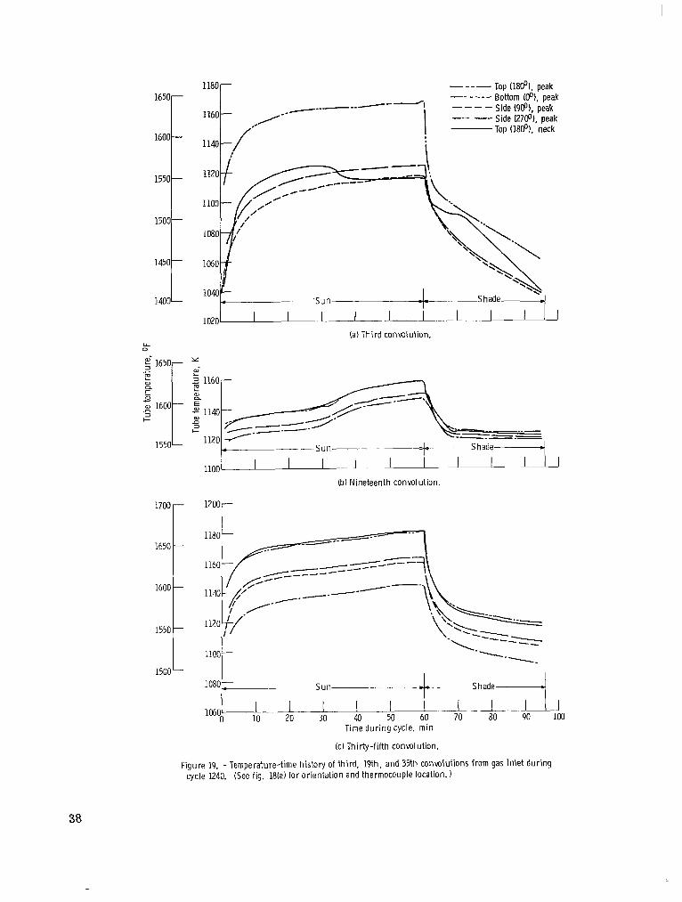
Thermocouples were attached to the convoluted tubes at five locations along the length of the tube. Figure 19 gives the temperature results during the 1240th sun-shade cycle for three of the convolutions - the inlet region, the middle region, the exit region. This cycle is very close to the end of the 2000-hour test, at which time results would be expected to be repeatable.
In each of these three regions, the highest temperature occurred at the convolution peak closest to the heaters, the lowest temperature at the convolution peak 180’ away. Comparing the regions, the higher temperatures on the convolution surface occurred in the region of high heat flux (in the vicinity of the inlet region) and where the convolutions became void of LiF (in the gas exit region). The greatest circumferential temperature spread at any location occurred in the gas inlet region where it ranged over 56 K (100’ F). The minimum spread was 14 K (25’ F) in the middle region.
Unexpected inflections are noticeable in many of the temperature curves. These may be attributed not only to the constant melting and freezing of LiF, but also to
16

change-of-phase volumetric expansion and contraction. These factors contribute to a constant shifting of liquid, solid, and void volumes within each convolution that can re- sult in the temperature irregularities.
DischargeTemperature
The working gas, He-Xe, was maintained at a constant flow rate and inlet temper- ature. The pressure drop between the inlet and the discharge measured 1 inch of water. The reading did not change with the sun and shade periods during a cycle.
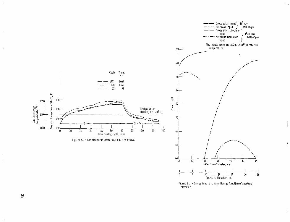
Figure 20 shows the discharge gas temperature during a full cycle at the beginning, in the middle, and toward the end of the test. The curves appear to exhibit the same trends as the convolution temperatures. The temperature increases relatively rapidly at the beginning of the sun period and then tends to level off. At the end of the sun pe- riod, the gas temperature drops sharply and again tends to level out. All three curves are shown on both sides of the design value of 1100 K (1500’ F). The gas temperatures ranged from 16 K (29’ F) below to 28 K (50’ F) above the design temperature. For the 32nd and 728th cycles, the discharge temperature was above 1100 K (1500’ F) for 56 minutes. For the 1251st cycle, the time above 1100 K (1500’ F) was 65 minutes.
CONCLUDINGREMARKS
The receiver was specifically designed to serve as the heat source for the ll-kilowatt-electric Brayton engine. However, the principle employed in the design of the cavity heat exchanger, as well as the heat-storage system, can be utilized for other heat engines. Where the fluid inlet temperature of such engines is different from that of the Bray-ton engine, the heat-storage tubes may be filled with materials having match- ing melting temperatures. For operation in the atmosphere, nonrefractory material of construction must be employed.
For the intended application, the structural design of the receiver is inherently for- giving of temperature maldistributions and hot-spot problems due to the material choice and the cavity configuration.
Among the functions of the solar Brayton heat receiver (to absorb, to store, and to transfer solar energy to the engine working fluid), the design of the heat-storage system is the most difficult. This is due to the large changes in volume which take place during melting and freezing in the heat-storage medium. For this reason, the testing of three heat-transfer/heat-storage tubes was undertaken.
17

The following results were noted: 1. The helium-xenon gas discharge temperature varied from 16 K (29’ F) below to
28 K (50’ F) above the design temperature of 1100 K (1500’ F) during the 2000-hour, 1250-cycle test.
2. The integrity of the bellows-shaped heat-storage tube remained intact. Swelling,
or bulging, of some of the lower convolutions was noted. Thermal performance was still satisfactory.
3. A shift in lithium fluoride (LiF) distribution had filled, and was responsible for the swelling of, the lower (inlet-end) convolutions and for the emptying of some discharge-end convolutions. The test results indicate a satisfactory performance of the tubes under conditions of earth gravity. In a zero-gravity environment, the LiF movement from one convolution to another is expected to be minimal. Consequently, the swelling of convolutions will be avoided, and the gas discharge temperature variations are expected to be greatly re- duced.
Lewis Research Center, National Aeronautics and Space Administration,
Cleveland, Ohio, February 22, 1972, 113-34.
18
APPENDIX A
RECEIVER SOLAR INPUT
Flux Distribution in Receiver Cavity
Solar radiation intercepted by the collector can be considered as parallel light cones each subtending an arc of 32 minutes. Given a perfect collector, with perfect orienta- tion, the axis of the reflected ray cones would pass through the theoretical focal point. As shown in figure 4, the center of the receiver aperture is located at the focal point. The light cones reflected from the rim area of the collector are incident on the receiver cavity wall near the beginning of the gas flow heat-transfer length, while the cones re- flected from the central areas of the collector are incident on the cavity walls near the end of the heat-transfer length.
The distribution of incident solar flux on the cavity walls is obtained from a digital computer program developed by Schrenk based on methodology described in reference 15. The program uses cone tracing from discrete points on the collector surface to deter- mine the flux distribution within the receiver cavity. It includes provisions for including the effects of random surface errors of the collector, orientation errors, vignetting (the effect of rays falling outside the given aperture), and shadowing (the effect of blockage of incident light on the collector by interposition of the receiver).
Aperture Size Optimization
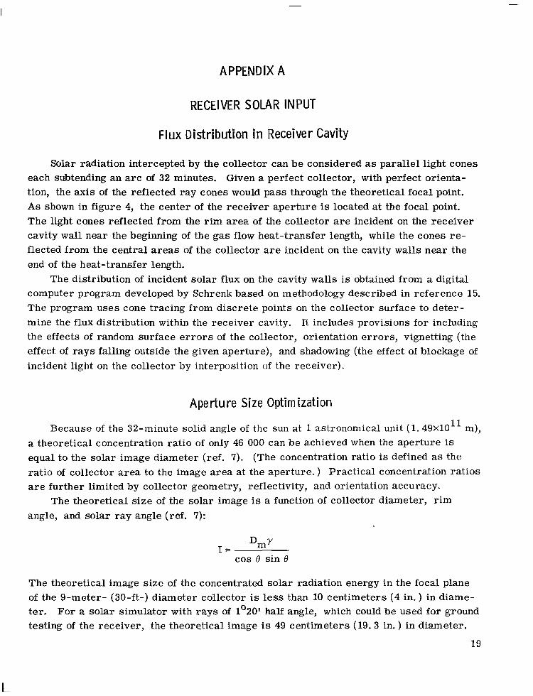
Because of the 32-minute solid angle of the sun at 1 astronomical unit (1. 49xlO’l m), a theoretical concentration ratio of only 46 000 can be achieved when the aperture is equal to the solar image diameter (ref. 7). (The concentration ratio is defined as the ratio of collector area to the image area at the aperture. ) Practical concentration ratios are further limited by collector geometry, reflectivity, and orientation accuracy.
The theoretical size of the solar image is a function of collector diameter, rim angle, and solar ray angle (ref. 7):
I Dmy = cos 0 sin 8
The theoretical image size of the concentrated solar radiation energy in the focal plane of the g-meter- (30-ft-) diameter collector is less than 10 centimeters (4 in. ) in diame- ter. For a solar simulator with rays of 1’20’ half angle, which could be used for ground testing of the receiver, the theoretical image is 49 centimeters (19.3 in. ) in diameter.
19

The diameter of the actual image is greater as a result of surface errors and mis- orientation of the sun-collector line and the receiver-collector axis. As the aperture size is increased to allow more input of solar radiation, the reradiation losses from the cavity interior are increased. The aperture size must therefore be optimized.
Schrenk’s flux distribution program is used to carry out the optimization. The flux input is summed for a series of cases with different apertures. Reradiation losses, based on the receiver design temperature of 1122 K (2020’ R), are computed for each aperture area; and these are deducted from the total energy input. The results are shown in figure 21 both for the sun and the sun simulator. The aperture of the flight receiver optimizes at 17. 8 centimeters (7 in. ) diameter. However, the reduction in net retained energy with a 20.3-centimeter (8-in. ) aperture is small enough to make it at- tractive to reduce the effect of misorientation. A 35.6-centimeter (14-in. ) aperture is about optimum for a simulator with rays having a half angle of 1’20’.
20
APPENDIX B
RESULTS OF STRESS ANALYSIS CALCULATIONS
A preliminary stress analysis was conducted on the initial receiver design (figs. 3 and 4) for the following environmental conditions: a ground test in a vacuum environ- ment operating in a temperature range of 1183 to 1222 K (1670’ to 1740’ F) for 10 000 hours. Thermal and mechanical stresses were determined in the primary areas to check the feasibility of the overall design using columbium - l-percent-zirconium (Cb-1Zr) material. The stresses were based on the operating conditions of the receiver as listed in table II, and they are illustrated schematically in figure 22.
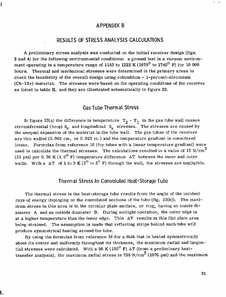
Gas Tube Thermal Stress
In figure 22(a) the difference in temperature T2 - Tl in the gas tube wall causes circumferential (hoop) S0 and longitudinal Sz stresses. The stresses are caused by the unequal expansion of the material in the tube wall. The gas tubes of the receiver are thin walled (0.063 cm, or 0.025 in. ) and the temperature gradient is considered linear. Formulas from reference 16 (for tubes with a linear temperature gradient) were used to calculate the thermal stresses. The calculations resulted in a value of 15 N/cm2 (23 psi) per 0. 56 K (1.0’ F) temperature difference AT between the inner and outer walls. With a AT of 1 to 3 K (2’ to 5’ F) through the wall, the stresses are negligible.
Thermal Stress in Convoluted Heat-Storage Tube
The thermal stress in the heat-storage tube results from the angle of the incident rays of energy impinging on the convoluted sections of the tube (fig. 22(b)). The maxi- mum stress in this area is in the circular plate surface, or ring, having an inside di- ameter A and an outside diameter B. During sunlight operation, the outer edge is at a higher temperature than the inner edge. This AT results in this flat plate area being strained. The assumption is made that reflecting strips behind each tube will produce symmetrical heating around the tube.
By using the formulas from reference 16 for a disk that is heated symmetrically about its center and uniformly throughout its thickness, the maximum radial and tangen- tial stresses were calculated. With a 56 K (100’ F) AT (from a preliminary heat- transfer analysis), the maximum radial stress is 738 N/cm2 (1070 psi) and the maximum
21

tangential stress is 1413 N/cm2 (2050 psi). These stresses are well within the accept- able limits.
Stress in Heat-Transfer Tube Due to Temperature Difference
Between Gas Tube and Heat-Storage Tube
The stress in the heat-storage tube (convoluted tube) is due to the temperature dif- ferential between the storage tube and the inner gas tube. If the gas tube is rigid, any change in length between the tubes must be accommodated by the heat-storage tube. The point of least load resistance in the convoluted tube is the flat plate area of the convolu- tion (fig. 22(c)). The dashed lines in the figure show the flat plate surfaces of the con- volution deflected due to the change in length between the heat-storage tube and the inner gas tube. With an estimated AT of 111 K (200’ F), a change of length between the tubes of 0.07 centimeter (0.028 in. ) takes place.
Using the average dimensions of the convolutions and case 14 of reference 16 for the determination of the stress in this flat plate area due to the deflection results in an average stress of 296 N/cm2 (430 psi) for a 111 K (200’ F) AT.
Gas Tube Stress Due to Internal Gas Pressure
The stress in the gas tube due to an internal pressure of 37 N/cm2 (54 psi) is 925 N/cm2 (1342 psi). This value is based on the hoop stress formula for cylinders
(ref. 16).
Gas Tube Stress Resulting From Temperature Differential Between
Gas Tube and Outer Rigid Shell
For each 56 K (100’ F) difference in the temperature of the gas tube and the outer shell, a difference in the length L of 0.036 centimeter (0.0144 in. ) exists (fig. 22(d)). This represents a stress of 2200 N/cm2 (3200 psi) if the gas tube is completely re- strained. The tube has a 90’ turn at the upper attachment to the manifold; therefore, the restraint is reduced since this elbow section can flex. If this section is allowed to deflect the total amount (0.036 cm, or 0.0144 in. ), a stress of 9900 N/cm2 (14 300 psi) in the elbow section of the tube would result (based on pipe bend formulas from ref. 17).
22

Since the AT could easily exceed 56 K (100’ F), the stress on the elbow section would be excessive. Therefore, the preliminary design was modified. A 23.6-centimeter (9. 3-in. ) straight section was added on this elbow. This reduced the stress to 970 N/cm2 (1410 psi) for a 56 K (100’ F) AT. Also, the addition of a straight section on the elbow required increasing the diameter of the outlet manifold (torus) from 127.6 centimeters (50.25 in. ) to 147. 3 centimeters (58.0 in. ).
Gas Tube Stress Due to Temperature Differential Between
Inlet and Outlet Manifolds
The stress due to the difference in the increase in the diameter of the outlet mani- fold relative to the inlet manifold caused by heating the receiver from room temperature to operating temperature is 100 N/cm2 (145 psi). This is based on a 867 K (1100’ F) inlet manifold temperature and a 1089 K (1500’ F) outlet manifold temperature. The in- crease in diameter of the inlet manifold is 0. 69 centimeter (0. 272 in. ), and the increase in the outlet manifold is 0. 74 centimeter (0. 290 in. ). This difference of 0.046 centime- ter (0.018 in. ) results in a movement of the gas tube at the attachment to the outlet manifold. This movement deflects the gas tube at point B (fig. 22(e)) and creates a flexural stress at point A. (B earn formulas from ref. 16 were used. )
Manifold Stresses Due to Internal Pressure
The pressure of the working fluid (gas) generates two stresses in the manifolds of the receiver; namely, a hoop stress and a meridional stress. Formulas for a torus under internal pressure were used (ref. 16). The stresses, wall thicknesses, and pres- sures for the two manifolds are listed in table VI.
TABLE VI. - MANIFOLD STRESSES
Inlet Outlet I I
23

Outer Shell Stress
The stress in the outer shell is developed by the weight of the outlet manifold, the top enclosure, and the insulation of these items (fig. 22(f)). For the upper cone the weight involved is 801 newtons (181 lb). For a 10-g launch environment this translates into a 8010-newton (1810-lb) load P. By using this load and the formulas from refer- ence 16 for conical sections, the stress is computed to be 15 400 N/cm2 (22 400 psi) and the deflection is 0. 38 centimeter (0. 15 in. ).
For the lower cone the weight is 1360 newtons (306 lb) and the 10-g load is 13 600 newtons (3060 lb). The stress from this load is 2084 N/cm2 (3020 psi) and the deflec- tion is 0.010 centimeter (0.004 in. ).
The stress of 2084 N/cm2 (3020 psi) for the lower section of the outer shell presents no problem, but the stress of 15 400 N/cm2 (22 400 psi) and a deflection of 0.38 centime- ter (0. 15 in. ) for the upper section could not be tolerated. The 0. 38-centimeter (0. 15-in. ) deflecting movement of the upper cone during the launch vibration mode would reflect in a stress being generated in the attached gas tubes. If they deflected this amount, the stress in the tubes would exceed the yield strength of Cb-1Zr. To lower this stress, the cone angle o must be increased, or reinforcing ribs must be used. In the final design the angle IY was increased to 45’ (from 25’140, and this reduced the stress to 3820 N/cm2 (5550 psi) and the deflection to 0.040 centimeter (0.016 in. ).
24
I

-
REFERENCES
1. Namkoong, David: Preliminary Test Results of Heat Transfer/Thermal Storage Tube Design under Simulated Orbital Conditions. NASA TM X-67904, 1971.
2. Anon.: Brayton Cycle Cavity Receiver Design Study. Rep. ER-6497, TRW Equip- ment Labs. (NASA CR-54752), Nov. 22, 1965.
3. Kemp, George D. : Steam Heat Receiver Experimental Evaluation. Rep. CORD- 65-21016, Sunstrand Aviation-Denver (AFAPL-TR-66-3, AD-480520), Feb. 1966. ,
4. Klann, John L. : Analysis and Selection of Design Conditions for a Radio-isotope Brayton-Cycle Space Powerplant. NASA TN D-4600, 1968.
5. Klann, John L. : Steady-State Analysis of a Brayton Space-Power System. NASA TN D-5673, 1970.
6. Jensen, Jorgen; et al. : Design Guide to Orbital Flight. McGraw-Hill Book Co., Inc. , 1962, p. 790.
7. McClelland, D. H. ; and Stephens, C. W. : Energy Conversion Systems Reference Handbook. Vol. II: Solar-Thermal Energy Sources. Rep. 390, vol. 2, Electro- Optical Systems, Inc. (WADD-TR-60-699, vol. 2), Sept. 1960, pp. H-A-108, H-A- 12, H-A- 14.
8. Burns, Raymond K. : Preliminary Thermal Performance Analysis of the Solar Brayton Heat Receiver. NASA TN D-6268, 1971.
9. Namkoong, David; and Lynch, Michael P. : Experimental Results of Heat Transfer and Pressure Drop of Argon Flowing Through Single Tube with Internal Interrupted Fins. NASA TM X-1428, 1967.
10. Nunner, Wolfgang: Heat Transfer and Pressure Drop in Rough Tubes. Rep. AERE- Lib/trans-786, United Kingdom Atomic Energy Authority, 1956.
11. Gnadt, P. A.: Filling Heat Storage Tubes for Solar Brayton-Cycle Heat Receiver with Lithium Fluoride. Rep. ORNL-TM-2732, Oak Ridge National Lab. (NASA CR-110776), July 1970.
12. Harrison, R. W.; and Hendrixson, W. H. : Compatibility of Columbium Based Al- loys with Lithium Fluoride. NASA CR-1526, 1970.
13. McCoy, H. E. : Creep Properties of the Nb-l%Zr Alloy. J. Less Common Metals, vol. 8, 1965, pp. 20-35.
14. Schmidt, F. F. ; and Ogden, H. R. : The Engineering Properties of Columbium and Columbium Alloys. DMIC Rep. 188, Battelle Memorial Inst. , Sept. 6, 1963.
25
L

15. Schrenk, G. L. ; and Gritton, D. G. : Analysis of Solar Reflectors. Mathematical Theory and Methodology for Simulation of Real Reflectors. Rep. EDR-3693, Allison Div. of General Motors Corp., Dec. 16, 1963. (Available from DDC as AD-602870. )
16. Roark, Raymond J. : Formulas for Stress and Strain. Fourth ed., McGraw-Hill Book Co., Inc., 1965, pp. 104, 221, 254, 306, 375, and 376.
17. Cracker, Sabin; and Sanford, Sterling S. : The Elasticity of Pipe Bends. Trans. ASME, vol. 44, 1922, pp. 555-556.
18. Greene, A. ; Sieber, H. ; Wells, D. ; and Wolfe, T. : Research Investigation to Determine Mechanical Properties of Nickel and Cobalt-Based Alloys for Inclusion in Military Handbook-5. Vols. 1 and 2. Republic Aviation Corp. (ML-TDR- 64-116, ~01s. 1 and 2), Oct. 1964.
19. Anon. : Haynes Corrosion Resistant Alloys - Hastaloy X. Union Carbide Corp., Oct. 1964.
20. Miller, George L. : Tantalum and Niobium. No. 6 of Metallurgy of the Rarer Metals. H. M. Finneston, ed., Academic Press, 1959.
26

” 7311 knf COP
I .I._..._
Collector (diameter 79.3 . 1 III 9 m (30 ft)) 20.0 N/cm.
(29.01 psia) -, - ! ITI
\a pr - ’ -292 K (526’R) /,- --- _.-.-~ 1
Primary radiator (prime area; 46.5 m2 (501 ft’))
Figure 1. - Schematic diagram of solar-powered Brayton pmerplant.
200 r
mo 2000 Orbit altitude, km
I---_~_L-~~...I-~ I I I I 100 200 500 MUI 2m 5000 10 m
Orbit altitude, n mi
Figure 2. - Sun and shade time as function of orbit altitude.
27
r ---i 1.47 m 1% in. 1
--Top enclosure
Heat-transfer and -storage tube -’
Inlet manifold
Door actuator
I 1.68 m (66 in. 1 *
Heat-rejection door (6)
-Aperture cone
Figure 3. - Brayton heat receiver final design.
28

-
I- 1.47 m t5t lin .)
Aperture
m ‘x- Upper cone
Outlet manifold -’ 1
‘\ L Inlet manifold
1.68m
CD-10051-03
P 1.23m (48.38hp4
Figure 4. - Cross section of receiver.

I I \/Collector \-Pocal plane
I- -I‘ 3.959 m 1155.884 in.)
Figure 5. - Collector-receiver relation.
Curve
- 1 Incident energy of real sun, using 9-m fM-ft). 1. I-tad- (60’) rim-anqle collector; ZO-cm- t8-in. -) diam aperture in receiver; and perfect orientation
--- 2 Incident energy with solar simulator, 2. 32x10S2-rad tl”20’) half angle, and 35-cm- (14-in. -1 diam aperture in receiver
--- 3 Heat extraction by gas stream
Position along tube, cm
Position along tube, in.
Figure 6. - Solar heat input on receiver walls and gas heat extraction,
30
I
8~10~
0-
4x10⁶ r Curve -1 Available sun energy for heat storage -s--2 Heat storage required for 33-min shade period
Position along tube, cm
L -l-- _I I I I I_-, 0 4 8 12 16 20 24 28 32 36
Position along tube. in.
Figure 7. - Heat-storage requirement and availability.
6~10~ r-
31 -L-II 300 400 500 --l-dir 9di--d 600 700 1300
Temperature, K
I-- - 4k 200
+-- I--- .--lL- I I I I 800 1200 1400 1600 1800 Temperature, OF
Figure 8. - Lithium fluoride specific volume as function of temperature.
31

LiF
(a) Precast lithitm fluoride.
welded to welded to outer outer tube with clearanc tube with clearanc to heat-transfer to heat-transfer
Gas tube-
0.076-cm tO.030-in. I diametrai clearance between gas tube and heat-storage tube --
Fill tube
Gas tungsten-arc weld (both ends)
/-Gas tube
Direction of gas flow
weld Figure 10. - Heat-transfer tube.
tc) Concentric tubes with spacer-separators. (bt Modules filled after assembly.
Figure 9. - Concepts for lithium fluoride containment.

_ .--
-&F
.-
.-;
Figure 11. - X-ray of lithium-fluoride-fill ed heat-trar lsfer and -storage tube assembly.

2.4
- Viscosity - - - Thermal conductivity
3.0 4% 6% 850 1050
Temperature, K 1250 1450 16%
I I 800 1200
I I 1600 2000
Temperature, OR
-I 2400 .--2800
Figure 12. - Viscosity and thermal conductivity of helium-xenon mixture. Molecular weight of He-Xe, 83.8.
34

r
Figure 13. - Heat-transfer tubes in test section Prior to test.
C-68-4079
Figure 14. -Tantalum heater wires in test section for solar heat flux simulation.
W ul
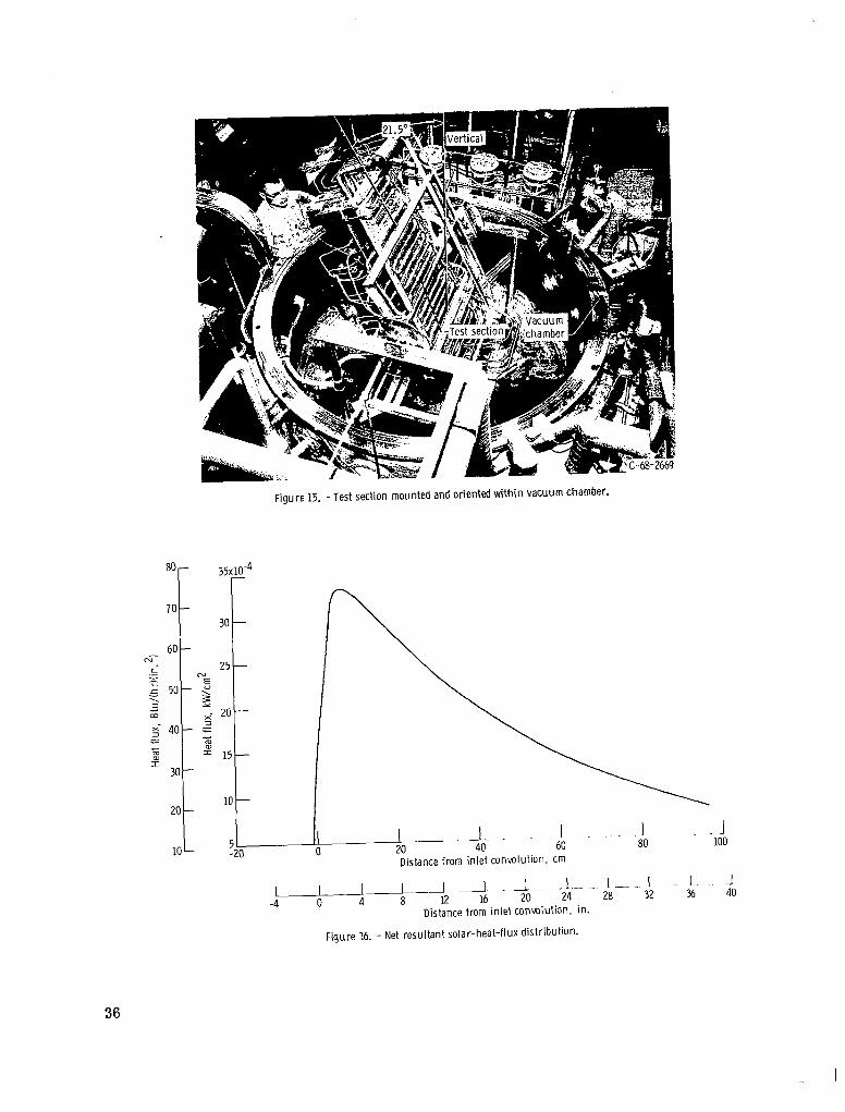
Figure 15. -Test section mounted and oriented within vacuum chamber.
EO- 35x10-4
70- 30 -
60- CT .c 25- = Jk 50- “E
5 g ;;I x- 20- 540- 2 = -G 2 = i? 15-
30 -
10 - 20 -
lo- 5 -20
Distance from inlet convolution, cm
I I I I I I 1 1 - --36 -4 0 4 8 12 16 20 ‘4--
&--- if
Distance from inlet conWlutiOn. in.
Figure 16. - Net resultant solar-heat-flux distribution.
36

- C-69-3919
figure 17. - Brayton receiver tubes in test section after 2002 hours of testing.
O0 ,-Lithium fluoride fill tube
/-Large convolution
l Thermocouple
Direction of heat input
(a) Sketch of convoluted tube shaving surface thermocouple locations and cross section.
(bl Radiographs of convolutions in inlet region. Voids within convolutions shun as white areas.
Figure 18. - Details of convoluted tubes.
37
1650-
1600-
1550-
1500-
1450-
MO-
O”
---- Top (18@), peak --- Bottom (81, peak ----Side (98), peak - - Side (278). peak -Top (188). neck
(a)Third convolution.
1650
1600
--Sun
-a
Ib) Nineteenth convolution.
Time during cycle. min
W Thirty-fifth conwlution.
80 90 100
Figure 19. -Temperature-time history of third, 19th, and 35th conwlutions from gas inlet during cycle 1240. (See fig. 18(a) for orientation and thermocouple location.)
38
Cycle lime, hr
--- 1251 2002 ----- 728 1166
32 51
s ,-
Sun 5 1050 l--TShadeI I 0 10 20 30 40 50 60 70 80 90 100
Time during cycle, min
Figure 20. - Gas discharge temperature during cycles
Gross solar input 161 ray - - - Net solar input half angle -- Gross solar simulator’l
input --- Net solar simulator
l”20’ ray half angle
input J -
W-- Net inputs based on 1122 K (20200 RI receiver
temperature
,.---, 76
t ‘1 \
7oi
681
I 4-
I ! ,/’
/ M--L -\ ! /
‘\ ‘1,
641 15 20
I /I I \I 25 30 35 40 45 Aperture diameter, cm
I I I I I I I 6 8 10 12 14 16 18
Aperture diameter, in.
Figure 21. - Energy input and retention as function of aperture diameter.
I
W co

40
(a)
, ,- Gastube
I r”1 I Tz TI ,e i- Heat storage tube
(b)
R ff3 r
T1
T2
(e)
(d)
P Outer shell
Figure 22. - Schematic illustration of thermal stress on convoluted tubes, manifolds, and outer shell.
NASA-Langley, wn - 3’ E- 6 740

NATIONAL AERONAUTICS AND SPACE ADMISTRATION
WASHINGTON. D.C. 20546 POSTAGE AND FEES PA,!,
OFFICIAL BUSINESS NATlONAL AERONAVTlCS AND
FIRST CLASS MAIL. SPACE ADMlNlSTRATlON .- PENALTY FOR PRIVATE “SE s.300
“The aeronautical and space activities of the United Staies shall be condzlcted so as to contribute . . . to the expansion of hzman knowl-
.edge of phenomena in the atmosphere and space. The Administration shall provide for the widest practicable and appropriate dissemination of information concerning its achities and the resldts thereof!’
-NATIONAL AERONAUTICS ANDSPACEACTOF 1958
NASA SCIENTIFIC AND TECHNICAL PUBLICATIONS
TECHNICAL REPORTS: Scientific and TECHNICAL TRANSLATIONS: Information technical information considered important, published h a foreign language considered complete, and a lasting contribution to existing to merit NASA distribution in English. knowledge.
TECHNICAL NOTES: Information less broad in scope but nevertheless of importance as a contribution to existing knowledge.
TECHNICAL MEMORANDUMS: Information receiving limited distribution because of preliminary data, security classifica- tion, or other reasons.
CONTRACTGR REPORTS: Scientific and technical information generated under a NASA contract or grant and considered an important contribution to existing knowledge.
SPECIAL PUBLICATIONS: Information derived from or of value to NASA activities. Publications include conference prpceedings, monographs, data compilations, handbooks, sourcebooks, and special bibliographies.
TECHNOLOGY UTILIZATION PUBLICATIONS: Information on technology used by NASA that may be of particular interest in commercial and other non-aerospace applications. Publications include Tech Briefs, Technology Utilization Reports and Technology Surveys.
Details on the availability of these publications may be obtained from:
SCIENTIFIC AND TECHNICAL INFORMATION OFFICE
NATIONAL AERONAUTICS AND SPACE ADMINISTRATION Washington, D.C; 40546