Preliminary design of a small-sized flapping UAV: I. Aerodynamic ...
Upload
nguyennhanCategory
view
216download
0
Noname manuscript No.(will be inserted by the editor)
Preliminary Design of a Small-Sized Flapping UAV.II. Kinematic and structural aspects
F. Negrello · P. Silvestri · A. Lucifredi ·J. E. Guerrero · A. Bottaro
Received: date / Accepted: date
Abstract The design of the actuating mechanism of a flapping wing unmanned-aerial-vehicle is addressed. Several configurations able to reproduce the desired flapping-wing kinematics are analyzed and an optimization study is conducted to select thebest configuration. The optimization results are used as the starting point for the de-sign of the different structural components of the flapping mechanism. During themechanism design stage, the linkages are optimized to match the desired wing’s mo-tion during a flapping cycle. A structural and durability analysis is then conducted toverify that the mechanism and its components are able to withstand the aerodynamicand inertial loads.
Keywords Flapping UAV · Biomimetics · Structural design · Flapping mechanism ·Ornithopter
1 Introduction
Recently, the engineering community has seen renewed interest in the low Reynoldsnumber aerodynamics of flapping wings for lift and thrust generation, and this ischiefly due to the growing interest of developing Unmanned-Aerial-Vehicles (UAVs),Micro-Air-Vehicles (MAVs) and, more recently, Nano-Air-Vehicles (NAVs). Thesevehicles may use or take advantage of such unconventional propulsion and lift gen-eration methods in order to achieve better performances than traditional methods.
UAVs, MAVs and NAVs are flying vehicles with no pilot on board, they are re-motely controlled or can fly autonomously based on pre-programmed flight plans.
F. NegrelloDepartment of Advanced Robotics, Istituto Italiano di Tecnologia, 30 via Morego, Genoa, 16163, ItalyE-mail: [email protected]
P. Silvestri, A.Lucifredi, J. Guerrero, A. BottaroUniversita di Genova, Scuola Politecnica, 1 via Montallegro, Genoa, 16145, Italy
2 F. Negrello et al.
These vehicles can perform surveillance and reconnaissance missions, sensing at re-mote or hazardous locations, traffic monitoring, forestry and wildlife surveys, inspec-tion of power lines and aerial photography, among other tasks.
In conventional man-made flying vehicles the wings provide the lift and the en-gines provide the thrust. In a bird, however, the wings have to provide the thrust aswell as the lift, with the added complication that they are also used to maneuver. Birdsare amazing examples of unsteady aerodynamics, high maneuverability, endurance,flight stability and control, and large aerodynamic efficiency.
A UAV that resembles a bird (a biomimetic UAV), experiences the same lowReynolds number as their biological counterparts, typically in the order of 103 to105; in this regime fixed wings drop dramatically in aerodynamic performance. Atthese low Reynolds number values, the fluid flow is prone to separation, resulting inincreased drag and loss of efficiency. Even without flow separation, the low Reynoldsnumber results in low lift-to-drag ratio due to the thickness of the boundary layer. Itbecomes clear that in order to develop a practical biomimetic UAV, new ways of gen-erating lift and thrust must be investigated with the aim of overcoming the drawbacksof fixed wings at low Reynolds number.
The most common way of producing rotating, oscillating or reciprocating motion,and hence flapping motion, is the four-bar linkage mechanism. Madangopal et al.[1], Malik et al. [2] and Zbikowski et al. [3] addressed the design, implementation,and testing of four-bar linkages for flapping MAVs. Another example can be foundin a patent by Kempf [4], where he describes a mechanism that generates a rigidflapping couple with a twist of the wing in a purely mechanical way and withoutthe need of using servo-actuators. The flapping motion is generated by a slider-cranklinkage, with the slider connected to the wings. To twist the wing, a second slider-crank mechanism is used with a different phase angle, equal to the desired torsionangle.
A pioneer in the studies of mechanical flapping-flight is DeLaurier [5–8], whoin the 1980s and 1990s conducted a series of experiments to assess the feasibility ofmechanical, powered, flapping-wing aircraft (the so called ornithopter). As a culmi-nation of two decades of research, DeLaurier successfully conducted flight tests of aremotely controlled scaled proof-of-concept model which provided the key analyticaltools for assessing the feasibility of the full-scale aircraft [8].
Recently, a team of researchers of the Festo company developed a prototype ofa robotic seagull named Smartbird [9]. The salient features of this robotic prototype,is the use of active torsion and partially linear kinematics [10]. Active torsion restson well established theoretical predictions in unsteady aerodynamics. The concept ofpartially linear kinematics is inspired by zoological observations on flying locusts.When the wings flap upwards, the servo-motor for the active torsion turns the outerwing from a positive angle of incidence within a short fraction of the flapping periodinto a negative angle of incidence. Between the turning points the angle of torsionremains constant. Although the results presented in reference [10] are impressive,some issues remain, such as the number of degrees of freedom required for the wingkinematics to yield efficient flight or the durability and structural limits of the flappingmechanism and wing structure.
Preliminary Design of a Small-Sized Flapping UAV 3
When designing a biomimetic flapping UAV, we should address the aerodynamicperformance of the flight vehicle, as well as the static and dynamic stability, the de-sign of the flapping mechanism, the structural integrity of the flight vehicle com-ponents, and the mechanical performance of the flapping UAV. Hereafter, we focusour attention on the design of the flapping mechanism and its different structuralcomponents. We also conduct a structural and durability analysis to verify that themechanism and its components are able to withstand the aerodynamic and inertialloads. The computation of the aerodynamic loads to be used in the structural studyand the design of the mechanism is addressed in reference [11].
The remainder of this manuscript is organized as follows. In section 2 we brieflyreview the design specifications, the avian model and design assumptions. In section3 we briefly discuss the wing kinematics and the identification of the design vari-ables of the mechanism. In section 4 we discuss the required degrees of freedomfor the proposed flapping kinematics and the synthesis of the wing actuation mech-anism. Section 5 describes the optimization of the mechanism linkages. In section 6the mechanism structural design and its limits are discussed. In sections 7 and 8 wereport the results on the durability analysis and the vibrations excited during the wingflapping, respectively. Finally, in section 9 conclusions and perspectives are outlined.
2 Design specifications, avian model and design assumptions
In table 1, the design specifications of the proposed biomimetic flapping UAV areshown. One important design specification to highlight is that the flapping frequencycan be modulated, but shall not exceed 3.0 Hz; this constraint is imposed for mechan-ical, structural and energy-consuming reasons. It is also interesting to point out thatthe vehicle is intended to be hand launched with a minimum velocity of 5.0 m/s.
Table 1 Design specifications.
Maximum Mass 1.0 kgMaximum flapping frequency 3.0 HzMinimum Velocity (hand launch velocity) 5.0 m/sMaximum Velocity 14.0 m/sAutonomy 20.0 min
We then proceed to look for birds that closely match the specifications outlined intable 1. The model shape, size, and flight conditions are chosen to approximate thoseof the gulls family. In reference [11] the full details of this study are explained. Also,the initial sizing and the layout of the avian model is presented.
It is important to stress that the flapping frequency is the most limiting designvariable. The final configuration of the flapping mechanism and the design of thewings structural components (therefore the final weight) depend on this design pa-rameter. High flapping frequency values imply high aerodynamic loads, high inertialloads and increased energy consumption.
Hereafter, we list a few design assumptions used during this study:
4 F. Negrello et al.
– The wings are considered to be made of two parts, one internal semi-wing andone external semi-wing. The wings are articulated at the joints between the semi-wings.
– The avian model and its individual components are treated as rigid bodies.– The components of the mechanism (crank, servo-motor, gearbox, batteries, levers,
etc.) are housed in the fuselage. The fuselage is assumed to have a light shellmaking it look like a bird.
– The wings cross section is the high-lift airfoil Selig 1223 and it is assumed thatthe flapping mechanism fits within the wing thickness.
– The wings motion can be represented by two degrees of freedom, namely, flap-ping and spanning.
– The wings have low inertia.
Of the previous design assumptions, the most prohibitive one is the restrictionrelated to fact that the flapping mechanism must fit within the wing thickness. Duringthe structural design phase, it might happen that in order to withstand the aerody-namic loads, the thickness of the components of the flapping mechanism is locallylarger than the maximum thickness of the wing, hence this will require a slight modi-fication of the wing and this in turn might affect the aerodynamic performance of theavian model.
3 Wing kinematics
From a kinematic point of view, birds’ wings have four degrees of freedom (DOF),namely:
– Flapping: which is the angular motion about the aircraft axis. This DOF generatesa rolling motion of the wings.
– Lagging: which is the angular motion about a vertical axis. This DOF generatesa back and forth motion of the wings.
– Feathering: which is the angular motion about an axis perpendicular to the planegenerated by the axes of the flapping and lagging motions. This DOF generates avariation of the wings angle of attack.
– Spanning: which is the enlargement and contraction motion of the wings. ThisDOF implies that the wings are articulated and can fold.
In this study, we consider that the wings motion only exhibits two DOF, namely,flapping and spanning. According to Guerrero et al. [11], the most important variablesto consider for the design of the flapping mechanism are:
– Aiw: which is the maximum roll amplitude of the internal semi-wing.– Aie: which is the maximum angle between the internal semi-wing and the external
semi-wing.– S: which is the fraction of time used during the upstroke. This value varies be-
tween 0 and 1. A value of 0.6, for example, means that 60% of the flapping periodis used for the upstroke; consequently, the angular velocity of the wing is lowerduring the upstroke.
Preliminary Design of a Small-Sized Flapping UAV 5
The kinematics described in reference [11] is obtained after an extensive cam-paign of computational fluid dynamics (CFD) simulations. The kinematics used byGuerrero et al. [11], apart from the fact that it generates thrust and enough lift tokeep the avian model aloft, might not be optimal from an aerodynamic point of view.Nevertheless, this kinematics is used as the starting point for the design and sizing ofthe flapping mechanism and structural components.
4 Synthesis of the flapping mechanism
To synthesize the flapping mechanism, we use as design parameters the variablesshown in table 2, where Aiw is the maximum stroke angle or roll amplitude of theinternal semi-wing and Aie is the maximum angle between the internal semi-wingand the external semi-wing, as described in reference [11]. S is the fraction of timeused during the upstroke.
Table 2 Design parameters for the flapping mechanism.
Aiw ≈ 60◦
Aie 45◦ ≤ Aie ≤ 50◦
S 0.5 ≤ Tcycle ≤ 0.65
Considering the possible combinations of stroke angles and flapping frequencies,the inertia of the wings should be low enough to ensure that the batteries can operatefor a sufficiently long time; therefore, it is required to position inside the fuselage ofthe avian model the mass related to the active actuation of the flapping mechanism,i.e., the servo-motor and the gearbox. It is also required to have a light wing structure.On the other hand, the wings must be sufficiently robust to withstand the aerodynamicand inertial loads.
The goal is to design a mechanism that couples the two DOF of the wing motion(flapping and spanning) into one mechanical DOF, by using a mechanical linkage thatrespects the design constrains given in table 2. Additionally, the mechanism must fitwithin the fuselage and wings, i.e., it must respect the geometrical constraints.
The minimum number of binary members required to design the flapping mech-anism for each semi-wing is four. The four-bar linkage provides kinematic pairing,good behavior at high speed and does not suffer of wear problems caused by elevatedcontact forces.
The configuration chosen for the four-bar linkage that drives the internal semi-wing is the crank-rocker type, which has as input the continuous rotational motion ofthe servo-motor and as output an oscillating moving arm. This mechanism is designedaccording to the Grashov rule [12]. For the external semi-wing, a double rocker con-figuration is adopted (non-Grashov condition). The wing structure, is attached to oneof the rockers of the external wing and to the rocker of the internal wing.
In summary, the flapping mechanism consists of two four-bar linkage in a serialconfiguration, where the conrod of the first four-bar linkage is the input of the secondlinkage.

6 F. Negrello et al.
L1
Y
Z
l1
l2
l3
l4
l5
l6
l8
l7
Fig. 1 Schematic representation of the flapping mechanism.
Using figure 1 as a reference, the length of the first member of the first four-barlinkage is indicated with l1 (this first member will be henceforth denoted with thesubscript 1, and similarly the other parts of the mechanism). In the same way, thelength of the input crank is indicated with l2, the length of the conrod is denoted withl3, and the length of the rocker is denoted with l4. For the second four-bar linkage, weindicate with l5 the length of the rod, with l6 the length of the output rocker 6, with l7the length of the input rocker 7, and with l8 the length of the rod 8.
5 Optimization of the kinematic model
The parameters of interest for describing the flapping motion are Aiw and Aie. For thepreliminary sizing of the mechanism, we express the dependency of these variablesin function of the lengths l2, l3, and l4, as follows:
Aiw = f (l2, l4); (1)
Aie = f (l2, l3). (2)
The length l1 does not appear as it is used as a normalization parameter for the mech-anism. By using equations 1 and 2, we can proceed to find the initial lengths of thelinks 1, 2, 3, and 4 (refer to figure 1); these initial values must respect the kinematicsand geometrical constrains. Then, these initial values are used as starting point for theoptimization study, where we aim at obtaining the optimal length of the members ofthe mechanism that reproduce with the minimum error the wing kinematics describedin reference [11].
For the optimization study, we use the optimization package integrated in themulti-body dynamics software LMS Virtual.Lab [13]. Inside LMS Virtual.Lab, we

Preliminary Design of a Small-Sized Flapping UAV 7
proceed to create a parametric model representing the length of the members withthe mechanical and geometrical constraints. The problem is fully decoupled sincethe variables of each semi-wing are independent, so it is possible to perform theoptimization of each mechanism in two separated steps. The driver of the motion isthe crank, and the angles of the internal semi-wing and external semi-wing are thosebetween the links 1-4 (Aiw) and 4-6 (Aie), respectively.
For the optimization study of the internal wing, the design variables are Aiw andS (refer to table 1). In this optimization problem we evaluate Aiw as follows:
Aiw = ATiw −AB
iw =
{arccos
[(l2
4 − (l3 + l2)2 + l21)
(2l1l4)
]− arccos
[(l2
4 − (l3 − l2)2 + l21)
(2l1l4)
]}360◦
2π; (3)
this equation is derived by taking the difference of the angular position of the rockerbelonging to the internal wing at the top-most (AT
iw) and bottom-most positions (ABiw).
The first objective function for the optimization of the mechanism of the internalsemi-wing is the error ε1 defined as,
ε1 = (Aiw −60◦)2. (4)
The flapping period and the crank positions θ T2 and θ B
2 are correlated; in ourdiscussion θ T
2 corresponds to the top-most position of the rocker and θ B2 corresponds
to the bottom-most position. Then, the angular range θ2 defining the input crankrotation during the upstroke is defined as,
θ2 = θT2 −θ
B2 =
{arccos
[(−l2
4 +(l3 + l2)2 + l21)
(2l1l4)
]− arccos
[(−l2
4 +(l3 − l2)2 + l21)
(2l1l4)
]}360◦
2π+180◦; (5)
this equation is derived by taking the difference of the angular position of the inputcrank at the top-most position (θ T
iw) and bottom-most position (θ Biw) of the internal
wing.To obtain different angular velocities during the upstroke and down-stroke, we
use the design variable S which is in the range 50% ≤ S ≤ 65%.Then, the second objective function is defined as
ε2 = (θ2 −S×360◦)2, (6)
where we use four values for S, namely: 50, 55, 60 and 65%. At this point, we canstart the multi-objective optimization study, where the goal is to minimize the valueof ε1 and ε2.
For the two objective functions related to the internal semi-wing, a DOE (designof experiment) is performed, where the lower limits of the design variables are de-fined in terms of the structural strength. The choice of the upper limits is dictated by
8 F. Negrello et al.
the maximum physical dimensions allowed (geometrical constraints). Then the opti-mization is performed by using a gradient based Pareto-set method, where we givedifferent weights to the individual objective functions and the collection of computedoptimal solutions form a Pareto set. The two objective functions are competitive, i.e.,optimizing the first objective function generates a larger error in the second objectivefunction. As a consequence, the best results are obtained when a large weight is givento the second objective function. The final results of this study are presented in tables3 and 4, where in table 3 we show the error between the final result and the targetvalue; and in table 4 we show the optimal values for the lengths l2, l3, and l4.
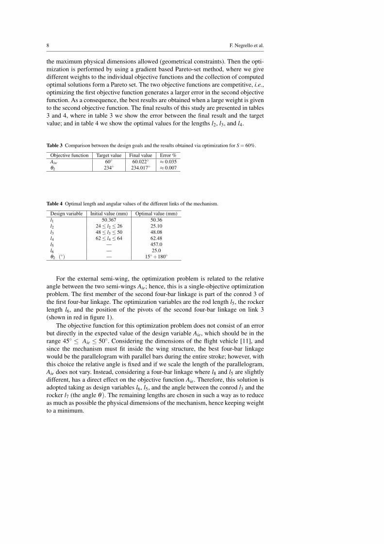
Table 3 Comparison between the design goals and the results obtained via optimization for S = 60%.
Objective function Target value Final value Error %Aiw 60◦ 60.022◦ ≈ 0.035θ2 234◦ 234.017◦ ≈ 0.007
Table 4 Optimal length and angular values of the different links of the mechanism.
Design variable Initial value (mm) Optimal value (mm)l1 50.367 50.36l2 24 ≤ l2 ≤ 26 25.10l3 48 ≤ l3 ≤ 50 48.08l4 62 ≤ l4 ≤ 64 62.48l5 — 457.0l6 — 25.0θ2 (◦) — 15◦+180◦
For the external semi-wing, the optimization problem is related to the relativeangle between the two semi-wings Aie; hence, this is a single-objective optimizationproblem. The first member of the second four-bar linkage is part of the conrod 3 ofthe first four-bar linkage. The optimization variables are the rod length l5, the rockerlength l6, and the position of the pivots of the second four-bar linkage on link 3(shown in red in figure 1).
The objective function for this optimization problem does not consist of an errorbut directly in the expected value of the design variable Aie, which should be in therange 45◦ ≤ Aie ≤ 50◦. Considering the dimensions of the flight vehicle [11], andsince the mechanism must fit inside the wing structure, the best four-bar linkagewould be the parallelogram with parallel bars during the entire stroke; however, withthis choice the relative angle is fixed and if we scale the length of the parallelogram,Aie does not vary. Instead, considering a four-bar linkage where l8 and l5 are slightlydifferent, has a direct effect on the objective function Aie. Therefore, this solution isadopted taking as design variables l6, l5, and the angle between the conrod l3 and therocker l7 (the angle θ). The remaining lengths are chosen in such a way as to reduceas much as possible the physical dimensions of the mechanism, hence keeping weightto a minimum.
Preliminary Design of a Small-Sized Flapping UAV 9
The objective function related to Aie is again computed using the multi-body dy-namics software LMS Virtual.Lab [13], where a virtual model of the system kine-matics is created. To compute the relative angular velocity we define a virtual angularvelocity sensor on the members under consideration (l6 and l8), and then we integratethe output of the virtual sensor over a period of oscillation. The range of acceptabilityof the maximum relative angle between the two semi-wings is the result of a com-promise between the aerodynamic requirements and the structural strength of the realcomponents.
This objective function (which expresses the relative angle between the two semi-wings), when applied to the four-bar mechanism, is proportional to l6 and inverselyproportional to the angle θ . The parameter l5 is chosen so that the relative angle fallswithin the desired range.
To solve this optimization problem, we use again a gradient based method. Thesolution does not present convergence issues, since the starting configuration is notfar from the optimal value. Table 5 summarizes the optimal solution achieved.
Table 5 Comparison between the design goals and the results obtained via optimization.
Objective function Target value Best ValueAie 45◦ ≤ Aie ≤ 50◦ 47.7◦
6 Design goal and structural analysis
The system under consideration is a compromise between weight, aerodynamic per-formance and structural strength, as the final goal is to design a biomimetic flappingUAV able to generate lift and thrust and, at the same time, the flapping mechanismand wing structure must withstand the aerodynamic and inertial loads of the flappingmotion.
To conduct the preliminary structural study, we use aluminum as a standard ma-terial for the mechanism. In table 6, the aluminum material properties used in thisstudy are reported. The material is assumed to be homogeneous and isotropic.
From the point of view of the structural design of the mechanism, we want alight and strong structure. To achieve the structural strength requirements a staticstructural analysis is carried out, where we initially assume that the loads are constantand equal to the maximum value of the aerodynamic loads plus the inertial loads
Table 6 Aluminum material properties.
Material property ValueYoung modulus (E) 7x10⁴ MPaPoisson ratio (ν) 0.346Density (ρ) 2710 kg/m3
Yield strain (Rp0.2) 440 MPaUltimate strain (Rm) 500 MPa
10 F. Negrello et al.
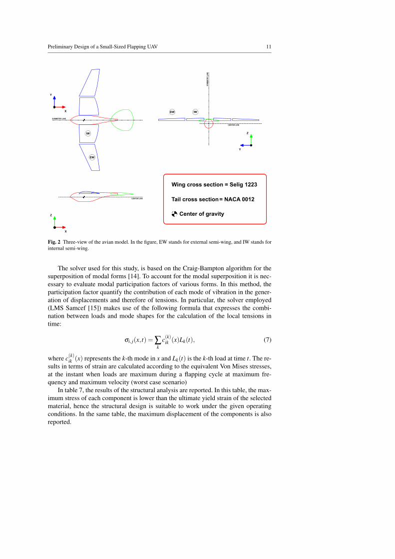
contribution, during a flapping cycle at maximum frequency and maximum velocity(worst case scenario). After verifying that the structure resists the maximum staticloads, an optimization study of the single components of the mechanism is carriedout using the dynamic loads during a flapping cycle. The aerodynamic loads are thoseobtained from the aerodynamic study [11] and the inertial loads are obtained usinga multi-body dynamics approach. With reference to the axes shown in figure 2, theloads which mainly affect the mechanism are:
– Primary bending of the wing in the y− z plane, as a consequence of the inertialand aerodynamic loads due to the flapping motion. To minimize the strain anddeflections due to the loads, it is appropriate to use sections with high moment ofarea.
– Secondary bending of the wing in the x− y plane, as a consequence of the aero-dynamic loads. To minimize this effect without penalizing the weight constraint,a ribbed structure with two light spars is used, creating in this a way a wing-box.
– Torsion around y axis, caused by asymmetric pressure distribution on the wingsurface and possible misalignment between the center of mass and the center ofpressure of the wing, when the wing is articulating. To minimize the torsion, wecan move the front spar closer to the center of pressure. However, this is difficultto obtain due to geometric constraints.
To better understand what components of the mechanism are more critical (interms of structural loads), hereafter we give a brief description of the mechanicalparts and the principal design choices.
The servo-motor is connected to the crank (2 in figure 1) by a gearbox; in thisdesign the crank is modeled as a gear with lightening holes to make the structurelighter. To achieve a 3.0 Hz flapping frequency, the angular velocity of the crank isset to 180 rpm. During the simulations, this value is reached after a short transient.The crank is comparable to a beam with two revolute joints at the ends, and the loadsare mainly distributed along the axis; there is also a secondary component of bendingbecause the joints are not aligned on the same plane.
The conrod (3 in figure 1) is the link between the motor input and the internalsemi-wing. It is responsible for extending and retracting the wing during the down-stroke and upstroke. This part is made as light as possible by using lightening holes.Tri-axial loads act on the conrod.
The internal semi-wing is attached to the rocker (4 in figure 1); it is designed toresist the aerodynamic and the inertial loads (dynamic and static) exerted on it.
The spar (5 in figure 1) transmits the motion to the external semi-wing, gener-ating the retraction and extension of the wing during the upstroke and down-stroke,respectively. It helps the mechanism resist primary bending; for this reason its shapeis studied to avoid buckling when the conrod is under compression (when the externalsemi-wing starts to extend).
The second conrod (6 in figure 1) represents the external semi-wing. This elementis critical due to its position. It must be as light as possible for inertia consideration,but it also needs to resist bending due to the high aerodynamic loads generated by thehigh angular velocities.
Preliminary Design of a Small-Sized Flapping UAV 11
S = 0.314w
S = 0.087h
MAC = 0.444h
MAC = 0.336w
Wing cross section = Selig 1223 Tail cross section= NACA 0012
CENTER LINE
SYMMETRY LINE
SYM
MET
RY L
INE
CENTER LINE
IWEW
EW
IW
Center of gravity
X
Y
X
Z
Y
Z
Fig. 2 Three-view of the avian model. In the figure, EW stands for external semi-wing, and IW stands forinternal semi-wing.
The solver used for this study, is based on the Craig-Bampton algorithm for thesuperposition of modal forms [14]. To account for the modal superposition it is nec-essary to evaluate modal participation factors of various forms. In this method, theparticipation factor quantify the contribution of each mode of vibration in the gener-ation of displacements and therefore of tensions. In particular, the solver employed(LMS Samcef [15]) makes use of the following formula that expresses the combi-nation between loads and mode shapes for the calculation of the local tensions intime:
σi, j(x, t) = ∑k
c(k)ik (x)Lk(t), (7)
where c(k)ik (x) represents the k-th mode in x and Lk(t) is the k-th load at time t. The re-sults in terms of strain are calculated according to the equivalent Von Mises stresses,at the instant when loads are maximum during a flapping cycle at maximum fre-quency and maximum velocity (worst case scenario)
In table 7, the results of the structural analysis are reported. In this table, the max-imum stress of each component is lower than the ultimate yield strain of the selectedmaterial, hence the structural design is suitable to work under the given operatingconditions. In the same table, the maximum displacement of the components is alsoreported.
12 F. Negrello et al.
Table 7 Results of the structural analysis for each element of the mechanism.
Component Max stress Max displacementCrank (l2) 300 MPa —Conrod (l3) 260 MPa —Rocker (l4) 200 MPa 4.75 mmSpar (l5) 280 MPa 2.55 mmSecond conrod (l6) 290 MPa 6.83 mm
Taking into account the harsh conditions under which the mechanism is working,the high aerodynamic and inertial dynamic loads due to the high flapping frequency(3.0 Hz), the stresses of the components and vibrations, it is of interest to performmore advanced studies such as, (i) a fatigue study and (ii) an analysis to find thevarious vibration modes and the natural frequencies of the structure. These issues areaddressed in the next sections.
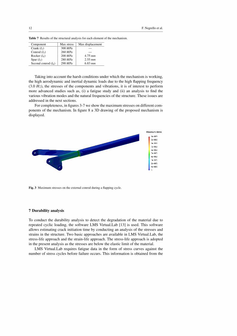
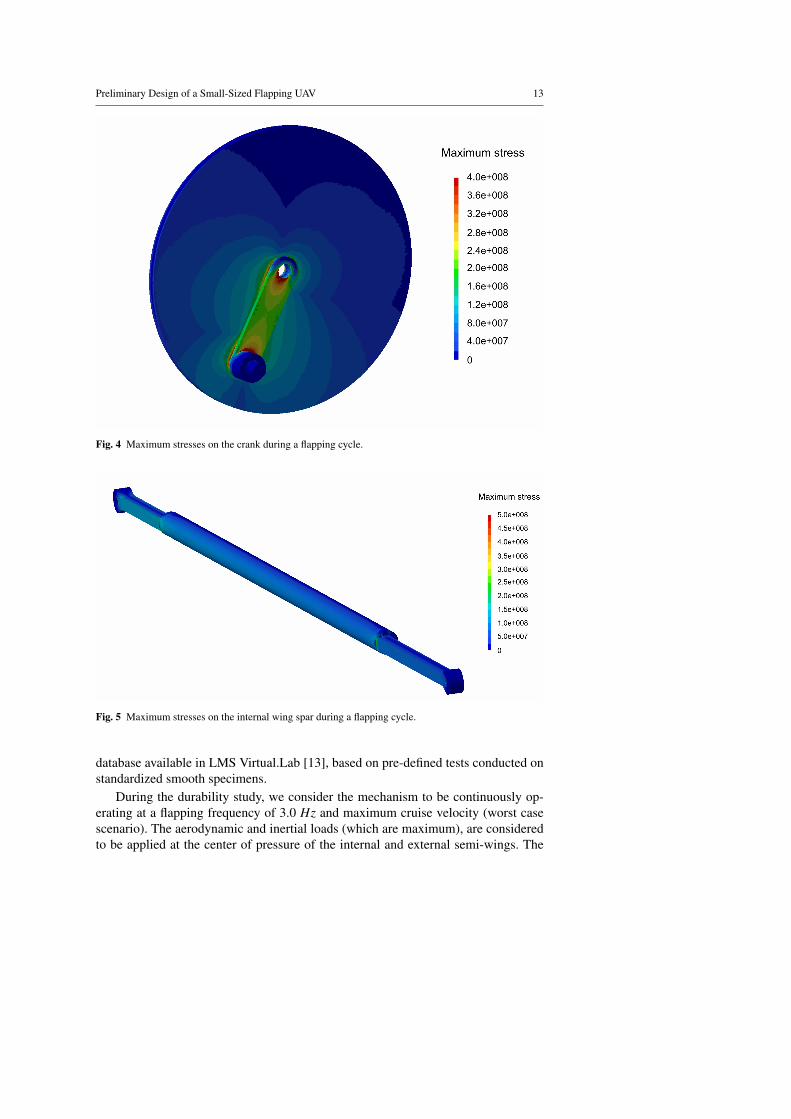
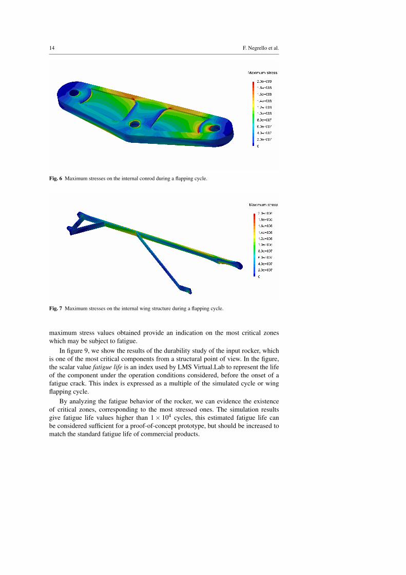
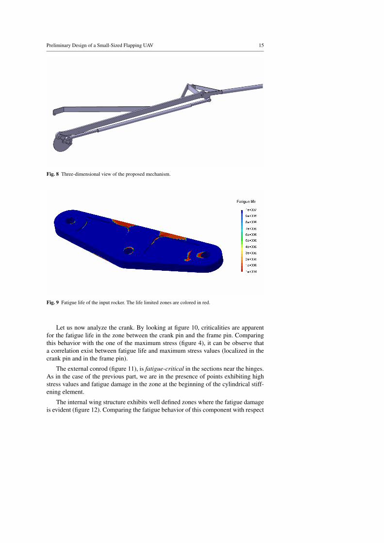
For completeness, in figures 3-7 we show the maximum stresses on different com-ponents of the mechanism. In figure 8 a 3D drawing of the proposed mechanism isdisplayed.
Fig. 3 Maximum stresses on the external conrod during a flapping cycle.
7 Durability analysis
To conduct the durability analysis to detect the degradation of the material due torepeated cyclic loading, the software LMS Virtual.Lab [13] is used. This softwareallows estimating crack initiation time by conducting an analysis of the stresses andstrains in the structure. Two basic approaches are available in LMS Virtual.Lab, thestress-life approach and the strain-life approach. The stress-life approach is adoptedin the present analysis as the stresses are below the elastic limit of the material.
LMS Virtual.Lab requires fatigue data in the form of stress curves against thenumber of stress cycles before failure occurs. This information is obtained from the
Preliminary Design of a Small-Sized Flapping UAV 13
Fig. 4 Maximum stresses on the crank during a flapping cycle.
Fig. 5 Maximum stresses on the internal wing spar during a flapping cycle.
database available in LMS Virtual.Lab [13], based on pre-defined tests conducted onstandardized smooth specimens.
During the durability study, we consider the mechanism to be continuously op-erating at a flapping frequency of 3.0 Hz and maximum cruise velocity (worst casescenario). The aerodynamic and inertial loads (which are maximum), are consideredto be applied at the center of pressure of the internal and external semi-wings. The
14 F. Negrello et al.
Fig. 6 Maximum stresses on the internal conrod during a flapping cycle.
Fig. 7 Maximum stresses on the internal wing structure during a flapping cycle.
maximum stress values obtained provide an indication on the most critical zoneswhich may be subject to fatigue.
In figure 9, we show the results of the durability study of the input rocker, whichis one of the most critical components from a structural point of view. In the figure,the scalar value fatigue life is an index used by LMS Virtual.Lab to represent the lifeof the component under the operation conditions considered, before the onset of afatigue crack. This index is expressed as a multiple of the simulated cycle or wingflapping cycle.
By analyzing the fatigue behavior of the rocker, we can evidence the existenceof critical zones, corresponding to the most stressed ones. The simulation resultsgive fatigue life values higher than 1 × 10⁴ cycles, this estimated fatigue life canbe considered sufficient for a proof-of-concept prototype, but should be increased tomatch the standard fatigue life of commercial products.
Preliminary Design of a Small-Sized Flapping UAV 15
Fig. 8 Three-dimensional view of the proposed mechanism.
Fig. 9 Fatigue life of the input rocker. The life limited zones are colored in red.
Let us now analyze the crank. By looking at figure 10, criticalities are apparentfor the fatigue life in the zone between the crank pin and the frame pin. Comparingthis behavior with the one of the maximum stress (figure 4), it can be observe thata correlation exist between fatigue life and maximum stress values (localized in thecrank pin and in the frame pin).
The external conrod (figure 11), is fatigue-critical in the sections near the hinges.As in the case of the previous part, we are in the presence of points exhibiting highstress values and fatigue damage in the zone at the beginning of the cylindrical stiff-ening element.
The internal wing structure exhibits well defined zones where the fatigue damageis evident (figure 12). Comparing the fatigue behavior of this component with respect

16 F. Negrello et al.
Fig. 10 Fatigue life of the crank. The life limited zones are colored in red.
Fig. 11 Fatigue life of the external conrod. The life limited zones are colored in red.
to the other parts of the mechanism, this component shows higher values of fatiguedurability, because it withstand lower stresses (figure 7).
Summarizing, the frame pivot and the crank pin are the most critical in termsof fatigue; the limited values of the fatigue life time reached in these zones (lowerthan 2000 cycles or 600 seconds operating at the maximum flapping frequency of 3.0Hz) might require a redesign of these components to render the mechanism durationacceptable. Areas of the rocker and other areas near the hinge points of the externalconrod also show criticalities. It is worth stressing the fact that the simulations are

Preliminary Design of a Small-Sized Flapping UAV 17
Fig. 12 Fatigue life of the internal wing structure. The life limited zones are colored in red.
performed in the worst case scenario (highest flapping frequency and cruise velocity).Operating at lower flapping frequencies and cruise velocities will yield significantreduction of the aerodynamic and inertial loads and therefore a better fatigue behaviorof the whole system.
8 Vibration modes in the different configurations of the linkage during thewing flapping
The results of a sequence of modal analyses of the mechanism in the various configu-rations adopted during the wings flapping cycle are reported hereafter. To get detailedinformation on the modal behavior during a flapping cycle, 20 different positions ofthe crank are considered, spaced at 18 degrees.
To conduct this study we use the simulation environment LMS Samcef [15]. Inthis study we link two numerical studies, namely, an implicit non-linear study and alinear modal study. The non-linear study evaluates the kinematic of the linkage forlarge crank rotations and the linear modal analysis is performed at the end of eachinstant of the non-linear study. This work flow is done in a fully automatic way.
To perform the modal analysis it is necessary to modify some constraints of thesystem, in particular the hinge constraint used in the linkage is substituted by a bush-ing joint. This is done because the hinge elements introduce a non-linear behaviorincompatible with the linearization assumption adopted for the computation of thevibration modes.
The methodology adopted makes it possible to numerically evaluate how the fre-quency of the vibration modes varies in the different configurations adopted by themechanism during a flapping cycle. In figure 13, we show the mode shapes of thefirst six modes for a crank angle of 0 degrees. In this figure, it can be evidenced thatthe first two mode shapes have bending characteristics.
Let us study the mode’s frequency while we vary the crank rotation angle, theseresults are shown in figure 14. In reference to the first mode (figure 14.a), we observe

18 F. Negrello et al.
0.9
0.8
0.3
0.4
0.5
0.6
0.7
0.2
00.1
A B
C D
E F
1.0 0.9 0.8 0.7 0.6 0.5 0.4 0.3 0.2 0.1 0
Fig. 13 Mode shapes of the first six modes of the mechanism for a crank position corresponding to θ=0.The first and second mode (a and in b in the figure) show bending characteristics. The third and fourthmode (c and d in the figure) shows torsional characteristics. The fifth and sixth modes (e and f in thefigure) show local bending characteristics in the internal part of the wing. In the figure, the green shape isthe undeformed geometry. The colored shape represents the deformed geometry (where the deformationhas been amplify).
that for crank angles of 0◦ ≤ θ ≤ 150◦, the vibration frequency values are low. Thismay be explained due to the elevated value of the moment of inertia of the systemwith respect to the direction normal to the mechanism plane. The increase of theinertia implies a reduction of the vibration frequency. The same observations can beextended to the second mode (figure 14.a), which also shows a bending mode shape.
Modes 3 and 4 (figure 14.b), present opposite behaviors with respect to the previ-ous modes. This may be explained by the torsional characteristics of the mode shape,
Preliminary Design of a Small-Sized Flapping UAV 19
the extension of the wing causes a reduction of the moment of inertia with respect tothe longitudinal direction of the linkage, which explains the increase of the frequen-cies of the modes.
Finally, modes 5 and 6 (figure 14.c) have mode shapes which display local bend-ing characteristics in the internal part of the wing, in this case the low sensitivity tothe inertia related to the position of the linkage in the vibration mode implies a lowsensitivity of the frequency to the variations of configuration of the linkage duringthe wing flapping.
Considering the frequencies of the first mode of vibration and the frequency cor-responding to the wing flapping (3.0 Hz), it is possible to evaluate if resonance con-ditions take place in the system. Analyzing figure 14, which reports the fundamentalfrequencies in the different configurations of the linkage, we can observe that the vi-bration modes frequency is always higher than the flapping frequency by at least 4times of the wing flapping frequency. Hence, it seems safe to claim that the systemdynamics is acceptable, since all the modes are weakly excited.
9 Conclusions and perspectives
The work presented in this manuscript is part of an ongoing multi-disciplinary effortaimed at designing a biomimetic flapping UAV. The multi-disciplinary study includesthe aerodynamic performance study, the static and dynamic stability study, the designof the flapping mechanism, the structural analysis study, and the mechanical perfor-mance study of the avian model.
The wing kinematics obtained from the CFD simulations is used as the startingpoint for the design of the flapping mechanism. An optimization study is then con-ducted to optimize the mechanism linkages. At the end of this study, a mechanismable to reproduce the proposed kinematics has been synthesized.
The proposed kinematics resembles that of nature’s fliers, produces thrust andlift, does not generate high angular velocities that could compromise the structuralintegrity of the avian model and, most importantly, we are able to design it by usinga four-bar linkage.
From this study, it is found that the preliminary mechanism and structural com-ponents withstand the static and dynamic loads generated by the flapping motion. Toreduce the inertia, the actuation group is located inside the fuselage which providesthe flight vehicle with an aerodynamic and protective shell. The wings are designedas light and strong as possible, so they have low inertia and do not fail under theoperating conditions.
The results obtained from the durability study yield fatigue life values higher than1×104 cycles, the estimated fatigue life can be considered sufficient for a proof-of-concept prototype, but should be increased to get a higher fatigue life for a reusableflapping UAV or comparable commercial product. From the vibration modes study, itis found that the inertia of the wings highly influences the vibration frequencies. It isalso found that we should be far from resonance conditions as the frequencies of allmodes are higher that the flapping frequency.

20 F. Negrello et al.
12
14
16
18
20
22
24
26
0 30 60 90 120 150 180 210 240 270 300 330 360
Freq
uenc
y (H
z)
θ (°)
Mode 1
Mode 2
40
45
50
55
60
65
70
75
0 30 60 90 120 150 180 210 240 270 300 330 360
Freq
uenc
y (H
z)
θ (°)
Mode 3
Mode 4
θ (°)
A
B
C
2
2
2
2
136
137
138
139
140
141
142
0 30 60 90 120 150 180 210 240 270 300 330 360
Freq
uenc
y (H
z)
Mode 5
Mode 6
Fig. 14 Frequency variation of the vibration modes during the motion of the mechanism.
Preliminary Design of a Small-Sized Flapping UAV 21
It is envisaged to conduct a structural study using lightweight, high-strength com-posite materials to achieve high performances. The idea is to use carbon fiber thatoffers high strength-to-weight ratios. The same multi-body dynamics package usedfor the design of the mechanism has been employed for the dynamic stability study.While we do not present here any results of this study, for the aerodynamic dampingcoefficient value used it is found that the flight vehicle has an acceptable responseto external perturbation and dynamic loads (aerodynamic and inertial). It is of in-terest to conduct wind tunnel tests to validate the CFD results, and get better esti-mates of the stability derivatives and aerodynamic damping coefficient in order toimprove/validate the dynamic stability study and devise efficient flight control laws.
Based on the results presented, the authors believe that it is feasible to build anoperational proof-of-concept model of the biomimetic flapping UAV. This representsthe next step of our work.
References
1. Madangopal, R., Khan, Z. A. and Agrawal S.K., Biologically Inspired Design of Small Flapping WingAir Vehicles Using Four-Bar mechanisms and Quasi-steady Aerodynamics, Journal of MechanicalDesign, July 2005, Vol. 127.
2. Malik, A.M., Khalid M.S.U. and Barlas F., Modeling and Simulation of Kinematics for an ActiveFlapping and Pitching Mechanism, Proceedings of the World Congress on Engineering 2010 Vol. IIWCE 2010, June 30 - July 2, 2010, London, U.K. .
3. Zbikowski, R., Galinski, C., and Pedersen C.B. Four-Bar Linkage Mechanism for Insectlike FlappingWings in Hover: Concept and an Outline of Its Realization J. Mech. Des. 127(4), 817-824 (Jun 27,2005)
4. Kempf, A., Patent nFR2776937, 1999, France.5. Larijani, R. F. and DeLaurier, J. D., A Nonlinear Aeroelastic Model for the Study of Flapping Wing
Flight, Fixed and Flapping Wing Aerodynamics for Micro Air Vehicle Applications, edited by ThomasJ. Mueller, Progress in Astronautics and Aeronautics, AIAA, Reston, VA, 195, 399-428, (2001).
6. DeLaurier, J.D. and Harris J.M., A study of mechanical flapping-wing flight, The Aeronautical Journalof the Royal Aeronautical Society, October 1993.
7. DeLaurier, J.D., An aerodynamic model for flapping-wing flight, The Aeronautical Journal of theRoyal Aeronautical Society, April 1993.
8. DeLaurier, J.D., The Development and Testing of a Full-Scale Piloted Ornithopter, Canadian Aero-nautics and Space Journal, Vol. 45, No. 2, June 1999.
9. htt p : //www. f esto.com/cms/encorp/11369.htm10. Send, W., Fischer, M., Jebens, K., Mugrauer, R., Nagarathinam, A. and Scharstein, F., Artificial
hinged-wing bird with active torsion and partially linear kinematics, Congress ICAS 2012.11. Guerrero, J.E., Pacioselli, C., Pralits, J. O., Negrello, F., Silvestri, P., Lucifredi, A. and Bottaro, A.,
Preliminary design of a small-size flapping UAV. I. Aerodynamic Performance and Static LongitudinalStability, to be submitted 2014.
12. Sclater,N., Chironis,N.,P., Mechanisms and mechanical devices sourcebook, McGraw-Hill, 2001.13. LMS Virtual Lab R12 On-Line Help, Leuven, Belgium, 201314. Craig, R. and Bampton, M., Coupling of Substructures for Dynamics Analysis, AIAA Journal, Volume
6, No. 7, 1968, Pages 1313-1319.15. LMS Samcef Field 8.4 On-Line Help, Leuven, Belgium, 2013