PREFEASIBILITY REPORT FOR EXPANSION IN … Typical arrangement CFBC steam generator M/s. GNFC Ltd...
28
PREFEASIBILITY REPORT FOR EXPANSION IN COAL BASED COMBINED CYCLE POWER PLANT PROJECT PROPONENT: M/S. GUJARAT NARMADA VALLEY FERTILIZERS & CHEMICALS LTD D-II/8, Dahej-II Industrial Estate, At: Rahiyad, PO: Dahej, Ta: Vagra, dist: Bharuch-392130 MARCH - 2016 EIA Consultant: EXCEL ENVIRO TECH NABET Accredited EIA Consultant Organization TF-2 , Sun House, Old High Court Lane Off Ashram Road, Ahmedabad – 380 009 Tele-fax: 079–27542219, Cell: +91-98255 88910 Email: [email protected] Website : www.excelenviro.com
Transcript of PREFEASIBILITY REPORT FOR EXPANSION IN … Typical arrangement CFBC steam generator M/s. GNFC Ltd...

PREFEASIBILITY REPORT
FOR EXPANSION IN
COAL BASED COMBINED CYCLE POWER PLANT
PROJECT PROPONENT:
M/S. GUJARAT NARMADA VALLEY FERTILIZERS & CHEMICALS LTD
D-II/8, Dahej-II Industrial Estate, At: Rahiyad, PO: Dahej,
Ta: Vagra, dist: Bharuch-392130
MARCH - 2016
EIA Consultant: EXCEL ENVIRO TECH NABET Accredited EIA Consultant Organization
TF-2 , Sun House, Old High Court Lane Off Ashram Road, Ahmedabad – 380 009 Tele-fax: 079–27542219, Cell: +91-98255 88910 Email: [email protected] Website : www.excelenviro.com

M/s. GNFC Ltd (Dahej Unit) Prefeasibility Report
1
1 BACKGROUND:
GNFC is one of the leading Indian Companies in the business of manufacturing and selling Fertilizers and Chemicals. GNFC has commissioned 50,000 MT per annum Toluene Di-Isocyanate (TDI) at Dahej i.e. 45 km from Bharuch. At present, this PLANT has a Natural Gas Fired Boiler to meet the process steam requirements and the power requirement is met from GETCO at 220 KV level and stepped down to 11 KV, 3.3 KV and 415 V. The present requirement of power is about 12.5 MW, which may go up to 18 MW in the near future with implementation of future projects at this site.
Due to increase of Natural Gas prices, the generation of steam using natural gas fired boiler is found to be unattractive and uneconomical in present scenario. Hence, GNFC decided to set-up 18 MW Captive Cogeneration Power Plant (CCPP) at GNFC, Dahej considering advantages in terms of self sufficiency and economic advantages.
The CCPP consists of Circulated fluidized bed combustion (CFBC) Boiler, Controlled Extraction cum Condensate type Steam turbine, associated utilities and balance of plants like coal handling, Ash handling & disposal system etc. at GNFC, Dahej complex.
Process Water, DM Water, Cooling Water, Fire Water, Plant & Instrument Air etc. will be catered from existing facilities. No augmentation such utilities is envisaged presently.
Steam and power generation unit is proposed to be interconnected with the existing steam network and power network appropriately.
All the new facilities shall be installed by utilizing the spare space/land available at Dahej Unit.
It is proposed to optimally utilize the present capacities/ space/resources, wherever possible, for meeting the additional requirements by tightly integrating the existing and new facilities without any significant additional investment.
Proposed CCPP Project will provide employment of 50 persons for continuous operation. Out of them, 20 would be skilled and 30 would be unskilled persons.

M/s. GNFC Ltd (Dahej Unit) Prefeasibility Report
2
2 PROJECT DESCRIPTION M/s. Gujarat Narmada Valley Fertilizers & Chemicals Ltd. (GNFC) has already started manufacturing unit at Dahej; Ta: Vagra; Dist: Bharuch. The list of products and approved capacity are as under:
Name of products Production Quantity (MT/month)
Toluene Di Isocyanate (TDI) 5170
Meta Toluene Di Amine (MTD) 4170
Ortho Toluene Di Amine (OTD) 140
Hydrochloric Acid (30%) 15510
Sodium Hypo Chlorite 660
TDI:MDI Blend* (application is under process at GPCB) 1550
Location:
Location of the site on map is shown as below:
Locaiton of site showing salient fatures in 5-km Radius

M/s. GNFC Ltd (Dahej Unit) Prefeasibility Report
3
Locaiton of site showing salient fatures in 500-m Radius
Layout of premises showing existing and proposed facilites
M/s. GNFC Ltd (Dahej Unit) Prefeasibility Report
4
Alternate Sites:
The project proponent already has a manufacturing unit at plot no. D-II/8, GIDC-II, Dahej Industrial Estate, Ta: Vagra, dist: Bharuch. The major purpose of setting us a cogeneration power plant is for meeting electricity and steam requirement of existing unit. Hence, the project proponent has not considered any alternative site.
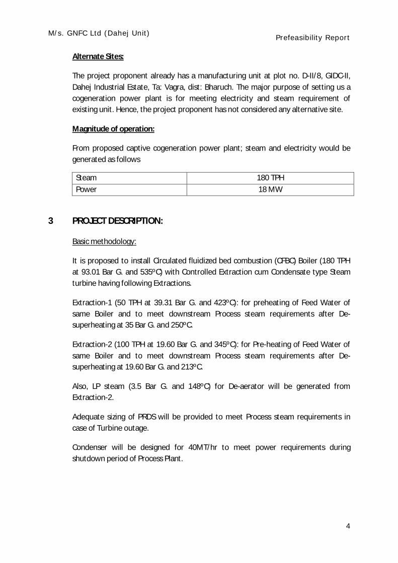
Magnitude of operation:
From proposed captive cogeneration power plant; steam and electricity would be generated as follows
Steam 180 TPH Power 18 MW
3 PROJECT DESCRIPTION:
Basic methodology:
It is proposed to install Circulated fluidized bed combustion (CFBC) Boiler (180 TPH at 93.01 Bar G. and 535ºC) with Controlled Extraction cum Condensate type Steam turbine having following Extractions.
Extraction-1 (50 TPH at 39.31 Bar G. and 423ºC): for preheating of Feed Water of same Boiler and to meet downstream Process steam requirements after De-superheating at 35 Bar G. and 250ºC.
Extraction-2 (100 TPH at 19.60 Bar G. and 345ºC): for Pre-heating of Feed Water of same Boiler and to meet downstream Process steam requirements after De-superheating at 19.60 Bar G. and 213ºC.
Also, LP steam (3.5 Bar G. and 148ºC) for De-aerator will be generated from Extraction-2.
Adequate sizing of PRDS will be provided to meet Process steam requirements in case of Turbine outage.
Condenser will be designed for 40MT/hr to meet power requirements during shutdown period of Process Plant.

M/s. GNFC Ltd (Dahej Unit) Prefeasibility Report
5
Steam Turbine Generator:
Circulating Fluidized Bed Combustion (CFBC) technology utilizes the fluidized bed principle in which crushed (6-12 mm size) fuel and lime stones are injected into the furnace. The particles are suspended in a stream of upwardly flowing air (60-70% of the total air) which enters the bottom of the furnace through air distribution nozzle. The fluidizing velocity in circulating bed ranges from 3.7-9 m/sec. The fine particles (< 450 microns) are elutriated out of the furnace with flue gas velocity of 4-6 m/sec. The fine particles are then separated by cyclone and are partially cooled in a separate low velocity fluidized bed heat exchanger where the heat is transferred to the steam. The cooler fine materials are then recycled to the dense bed.
In CFBC design steam generator, the dense bed does not contain any in- bed tube bundle heating surface. The furnace enclosure and internal division wall type surfaces provide the required heat removal. This is possible because of the large quantity of solids that are recycled internally and externally around the furnace. Because of solid recycling (cyclone separator), the mass flow rate of the combustion gas, and furnace temperature remains uniform. The typical steam generator arrangement is shown in fig.
Fig: Typical arrangement CFBC steam generator

M/s. GNFC Ltd (Dahej Unit) Prefeasibility Report
6
STEAM GENERATOR & AUXILIARIES
Atmospheric fluidized bed type , natural circulation, single drum , top supported, water tube, balanced draft, semi outdoor installation, with under bed feeding system rated to deliver 180t/h of steam at 93.01 Bar G. and 535ºC. The steam generator would be designed for firing coal and TDI tar. The ratio of coal and TDI tar to be fired in the steam generator are being investigated by the steam generator suppliers. Natural gas will be used as a start up fuel.
The steam generator shall be complete with all pressure parts, steam generator mounting and fittings, economizer, tubular air pre-heater etc. The steam generator would be provided with bunkers for coal and bed material.
The draft plant would comprise 2 x 60% forced draft fans, 2 x 60% induced draft fans and 2 x 60% primary air fans with constant speed drive motors. Electrostatic precipitators (ESP) and fly ash hoppers would be provided for the collection of ash. The ESP would be designed to achieve an outlet flue gas dust concentration of lower than 30 mg/ Nm3 to meet the pollution control norms.
A RCC chimney with 110 m high will be provided to disperse the flue gas to atmosphere.
STEAM TURBINE GENERATOR & AUXILIARIES
The proposed steam turbine generator would have a maximum continuous rating of 18 MW at the generator terminals with throttle steam conditions of 93.01 Bar G. and 535°C and with condenser cooling by water cooled condenser. The steam turbine would be of single cylinder extraction cum condensing type. The turbine will have following sizing for extractions:
Extraction-1 (50 TPH at 39.31 Bar G. and 423ºC): for preheating of Feed Water of same Boiler and to meet downstream Process steam requirements after De-superheating at 35 Bar G. and 250ºC.
Extraction-2 (100 TPH at 19.60 Bar G. and 345ºC): for Pre-heating of Feed Water of same Boiler and to meet downstream Process steam requirements after De-superheating at 19.60 Bar G. and 213ºC.
Also, LP steam (3.5 Bar G. and 148ºC) for De-aerator will be generated from Extraction-2 only.
The turbine generator would be complete with all accessories such as protection system, lube and control oil systems, jacking oil system; seal steam system, turbine drain system, electro-hydraulic control system, and turbine supervisory instrumentation. Other

M/s. GNFC Ltd (Dahej Unit) Prefeasibility Report
7
accessories of the turbine generator would include an oil purification unit with transfer pumps, overhead lube oil tank for emergency oil supply, and clean and dirty oil storage tanks of adequate capacity.
FEED CYCLE EQUIPMENT Condensate Extraction Pumps
2 x 100% capacity condensate extraction pumps, one working and one standby, would be provided. The pumps would be vertical, canister type multistage centrifugal pumps.
Boiler Feed Pumps
Feed water would be pumped from de-aerator to the steam generator by means of 3 x 50% (2 working +1 standby) capacity boiler feed pumps. Pumps would be of horizontal, multistage, centrifugal barrel type construction.
Low Pressure Feed water Heaters
Horizontal U-tube type low pressure feed water heaters equipped with drain cooling, condensing zones and individual bypass system would be provided
De-aerator
The de-aerating feed water heater would be a direct contact, variable pressure type heater with spray-tray or spray type of de-aeration arrangement. The feed water storage tank would have a storage capacity adequate to feed the steam generator for at least 10 minutes when operating at MCR conditions.
Condenser
The condensing plant would comprise divided flow, double-pass, horizontal, surface type construction. The condenser would have SS tubes. Air ejector would be provided to remove the non-condensable gases liberated during normal operation
Gland Steam Condenser
A surface type gland steam condenser would be used to condense the gland steam exhausted from the turbine glands. The exhausters would be provided to evacuate the air from the shell side and maintain the shell at the required negative pressure.
COMPRESSED AIR SYSTEM
The instrument and service air requirements of the plant would be met from the existing compressed air system of the process plant.
The requirement of the compressed air for the fly ash conveying would be met through

M/s. GNFC Ltd (Dahej Unit) Prefeasibility Report
8
separate dedicated compressors.
NATURAL GAS SYSTEM
Natural gas will be used as a start up and stabilization fuel for the plant. The system will have necessary pressure control valves in order to meet the pressure requirement of the steam generator.
TDI TAR
About 20 MT/day TDI Tar will be used as a fuel along with coal. The detailed analysis report is tar is attached as annexure-1.
AIR CONDITIONING AND VENTILATION SYSTEM
It is proposed to air-condition the control and office rooms of TG building, CHS switchgear building, CEMS building. Inside design conditions of 24.5 oC dry bulb temperature and relative humidity not exceeding 60% would be maintained in all air- conditioned areas. Adequate number of split air conditioned units (numbers working + one stand by) would be considered for this purpose.
For the ventilation of the station building, evaporative cooling system (air washer type) is envisaged. The exhaust of hot air out of the station building would be achieved by provision of roof extractors and wall mounted exhaust fans.
For ventilation of other buildings, supply air fans or louvers, exhaust air fans or a suitable combination of these complete with louvers, filters, ducting & grilles would be provided.
CRANES AND HOISTS
Cranes and hoists with all accessories, supporting structure, power supply, safety devices and controls of required sizes and adequate capacities would be provided to facilitate the lifting and transporting of various parts of equipment during maintenance or replacement of the various plant components. Other miscellaneous monorails, trolleys and hoists required would also be provided. The station building EOT crane would be designed to use for maintenance purpose only. One EOT crane of 25/ 10t capacity would be provided in the station building.
WATER SYSTEM
The water requirement for the proposed power plants would be met from the existing facility of process water storage tank.

M/s. GNFC Ltd (Dahej Unit) Prefeasibility Report
9
The existing plant water system would consist of the following:
a) Condenser cooling water system
b) Auxiliary cooling water (ACW) system
c) DM Water & CPU Water transfer system
d) Service & potable water transfer system
e) Effluent transfer system
f) Chemical & chlorine dosing system
g) Fire protection system
Additionally the condensate water transfer pumps to return the process condensate from TDI plant back to proposed power plant.
Condenser Cooling Water (CW) System
The cooling of condenser is achieved through circulation of cooling water in a wet cooling system. This requirement will be catered from existing cooling tower.
Make-up Water System and CW Blow down
It is proposed to draw CW make water from existing process water storage tank. Filtered water from the filtered water storage tank would be supplied to the cooling tower basin as make-up for CW system.
It is proposed to design the cooling water circuit to operate at an optimum cycle of concentration i.e., COC level of 5 in order to limit fresh water consumption and minimize blow down. The blow down water would be utilized for other plant fresh water requirement such as coal and ash handling system, with a view to achieve max reuse of plant effluents. Necessary chemical dosing systems with anti scalant / dispersant / corrosion inhibitor chemicals like concentrated sulphuric acid, chlorine to prevent scale formation / fouling/ corrosion shall be provided. Monitoring equipment like depositor monitor/ fouling monitor, bio-fouling monitor, corrosion test coupon test racks, online instant corrosion rate monitor and online pH monitor would be provided.
CW make up shall be provided from filtered water storage. The quality of circulating water shall be determined by laboratory analysis of grab samples and by conductivity measurements at cooling tower side as well as the condenser side. Accordingly the chemical dosing system shall be operated. Make up to CW system shall be automatically controlled through inching type butterfly valves and level controller in CT basin.

M/s. GNFC Ltd (Dahej Unit) Prefeasibility Report
10
The CW blow down would be taken from the cooling tower basin and then directed to the CW blow down tank. Water from CW blow down tank would be utilized for cleaning/washing of coal handling area and cleaning of silo area of ash handling system. The surplus quantity will be sent to ETP.
Auxiliary Cooling Water (ACW) System
The ACW system is to cater the cooling water requirements of all the auxiliary equipment such as turbine lube oil coolers, generator air coolers, SG auxiliaries etc.
Cold water would be supplied by ACW pumps to various auxiliaries and return hot water will be led to cooling tower. Circulating water for auxiliaries cooling shall be tapped from the main CW pumps discharge and boosted by 3 x 50% capacity ACW booster pumps.
Water Treatment (WT) System
The requirement of demineralised water (DM) water for proposed facilities would be met from existing DM water storage tank. Also process condensate of re-usable quality would be tapped-off and utilized for plant make-up. Existing DM water plant and condensate polishing unit will be utilized for this purpose.
Necessary chemical dosing like morpholine/ ammonia, hydrazine and tri-sodium phosphate, etc., would be done in condensate, feed water and boiler drum respectively.
Process (Service) and Potable Water Systems
The process (service) water system would supply water required for coal handling systems, HVAC system, and miscellaneous water requirements of station building. 2x100% process water pumps would pump water from the existing process water tank to each consumer. Process water system shall be complete branch distribution network. Process water shall be utilized for ash handling compressor cooling also.
Requirements of potable water system would be met from the existing potable water storage tank. 2x100% potable water pumps would pump water from the existing potable water tank to each consumer. Potable water system shall be complete branch distribution network.
FIRE PROTECTION SYSTEM
Fire protection system for the proposed new facilities shall be done by extending the existing fire water network by taking tapings at appropriate locations. Requirement of fire water booster pumps (motor operated & standby diesel engine operated) shall be considered during detailed engineering to cater the remote pressure requirement as per

M/s. GNFC Ltd (Dahej Unit) Prefeasibility Report
11
Codes & Standards. Necessary fire water hydrants, water monitors, deluge spray system, portable fire extinguishers shall be provided as per fire design standards.
EFFLUENT TREATMENT SYSTEM
Effluent on zero discharge concepts would be adopted for the proposed plant except for the CW blow down. Water from CW blow down tank would be utilized for cleaning the coal handling system area, cleaning of silo area of ash handling system.
Boiler blow down shall be collected in a blow down sump located near SG area. The high temperature of blow down water would be brought down by adding cold water to SG blow down sump. 2x100% sump pumps each of required capacity and head would pump the quenched boiler blow down water from the blow down sump to cooling tower basin. Provision for tap-off from process water pumps to CT basin with flow control valves to be provided to quench the high temperature blow down water and bring it to ambient temperature. As an alternative arrangement bypass line with flow control valves, sized for full flow capacity would also be provided from SG blow down sump pump to raw water storage tank to take care of any unforeseen emergency situation when quenching of hot water is not possible. SG sump pumps shall be selected suitable for high temperature SG blow down water application.
Floor wash water from SG area would be collected in a separate sump of required capacity located near each SG area. Two numbers (1W+1S) submersible pumps per unit of suitable capacity and head would be provided to pump the floor wash water and lead the effluents to collection tank. The chemical drains from CW chemical & chlorination area would be led to neutralization pit by suitable sump pump.
Chemical Laboratory Equipment
Existing plant chemical laboratory equipments would be utilized to cater the requirement of proposed facilities. Coal testing facility will be additionally provided.
COAL HANDLING SYSTEM
The maximum daily requirement of coal would be about 754 tonnes considering the worst quality of coal based on maximum steam generation capacity in the steam generator. Total coal required would be about 0.236 million tonnes per year considering the plant load factor (PLF) as 0.85. Coal handling system is envisaged to operate for 8 hours in a day, and accordingly one of stream of conveyor and equipment are considered.

M/s. GNFC Ltd (Dahej Unit) Prefeasibility Report
12
Coal Receipt and Unloading at Site.
Coal would be received from SECL coal mines through railway mode using BOXN wagon at Bharuch unit of GNFC or Dahej railway yard, by railway wagons. The report considers presently that coal from railway wagons would be unloaded and loaded onto trucks using the existing facilities and sliding arrangement at Bharuch unit, since coal receiving arrangement at Dahej is still not finalized. Coal from Bharuch unit will be transported by trucks to TDI Dahej unit. Coal storage for 15 days is planned to meet the unexpected interruptions in coal supply. The maximum lump size of the coal would be about (-) 300mm.The coal will be unloaded through truck dump hoppers.
Coal requirement per day would be about 754 MT. Hence approx 30 No. of trucks per day, based on 25 MT payload capacity of truck, is expected to carry the coal to the site. The coal would be unloaded from trucks through tippler or self tippling system to the dump hoppers.
The coal is expected to be received either through self tippling trucks or non-tippling trucks, In order to facilitate the unloading of coal received through non-tippling trucks, 1 (one) No. of hydraulic truck tippler is proposed.
Coal Conveying System
The coal would be conveyed after two stages of crushing and one stage of screening to the boiler bunkers by combination of belt conveyors and pipe conveyors.
In order to ensure zero spillages inside the plant during conveying of coal, pipe conveyors are proposed wherever feasible.
Space provision is made in the form of storage silo to store about 15 days requirement of coal. Coal from the storage silo would be evacuated and fed to downstream conveyors by paddle feeders.
ASH HANDLING SYSTEM
The proposed ash handling system is based on the following design considerations:
a) Coal firing rate at MCR condition: 31.42 tph
b) Ash content: 21.2 %
c) Type of coal: Domestic or imported
d) Percentage distribution of total ash produced: Bottom Ash – 20%; Fly Ash – 80%
e) The systems envisaged for ash removal Bottom ash (BA) - Mechanical system

M/s. GNFC Ltd (Dahej Unit) Prefeasibility Report
13
Fly ash (FA) - Pressure pneumatic system
f) Location of disposal area: Ash generated in the plant will be stored in FA Silo and BA silo, with holding capacity of each silo will be 4 days generation rate.
g) Ash generation: Bottom ash and fly ash generated per day would be about 32 MT and 128 MT respectively.
Ash formed due to combustion of coal in the steam generator (SG) would be collected as bottom ash in the bottom ash hopper and as fly ash in the fly ash hoppers.
Bottom Ash Handling
The bottom ash is evacuated through respective bottom ash coolers and fed to the bottom ash silo through drag chain conveyor and bucket elevator.
Fly Ash Handling System
Pressure cum Pressure Type Pneumatic System
The fly ash collected at the ESP, Eco and APH hoppers would be gravity fed into individual transmitter vessels provided below each hopper. On initiation of fly ash collection system, the inlet valve would open and allow the fly ash to be fed into the transmitter vessel for pre-determined time after which the inlet valve would close. Afterwards, the conveying compressed air would be allowed to flow into the transmitter vessel by opening the air inlet valve. Once the desired conveying pressure is reached inside the vessel, the fly ash would be conveyed to the fly ash silo with the help of compressed air through transport piping. The conveying air would be vented through the bag filters mounted on top of the silo in order to limit the dust concentration in the vented air. The fly ash transmitter vessels connected to ESP hoppers in a particular column / row would be connected to common fly ash conveying pipe line.
Fly ash removal from all the hoppers in each field that are connected to common conveying line would be done simultaneously. The evacuation from any hopper would continue cycle after cycle till the level in the hoppers reaches low level. The evacuation of fly ash from any particular hopper would be initiated whenever the level in the hopper reaches predetermined level. Therefore the removal and transfer of the fly ash to the silos would be done in cyclic manner on a continuous basis.
Disposal of Ash from Fly Ash Silo and Bottom Ash Silo
The fly ash silo and bottom ash silo would be designed to have capacity to store ash generated for 4 days operation. The ash collected in the fly ash and bottom ash silo

M/s. GNFC Ltd (Dahej Unit) Prefeasibility Report
14
would be unloaded into closed trucks in dry form to prevent ash spillage from the trucks while taking the ash outside of the plant.
Raw material
The main raw material required for proposed project would be Coal to be received from South Eastern Coalfields Limited (SECL) Collieries. GNFC already has Memorandum of Understanding (MoU) with the company and Coal Lineage Document has been signed by both the parties.
The quantity of coal at full power generation capacity shall be 2,36,250 TPA.
Domestic Coal from SECL collieries is proposed to be received at GNFC, Bharuch or at Dahej railway yard. The design calorific value of the coal is around 5041 kcal/kg (GCV), while the worst calorific value of coal is around 4605 kcal/kg. The annual coal requirement for proposed coal fired captive cogeneration facility has been estimated to be about 0.236 MTPA for a plant load factor (PLF) of 85%, based on worst quality coal. Tentative analysis of coal is attached at Annexure-1.
Along with coal, about 20 MT/Day TDI tar will also be use in steam generator.
Coal requirement per day would be about 754 tonnes. Hence, approx 30 No. of trucks per day, based on 25 MT payload capacity of truck, is expected to carry the coal to the site. The coal would be unloaded from trucks through tippler to the dump hoppers.
Water requirement
Project Proponent already has existing unit at said location and the GIDC already supplies required water for plant.
For upcoming activities also, 3500 KLD water would be required, which would be sourced from GIDC water supply.
Hazardous/ waste generation and management
From the proposed project, following types of hazardous waste will be generated
SR No
Detail of Hazardous Waste
Category Quantity Management and
disposal
1. Used oil/spent oil 5.1 12 KL/year
Collection, storage, transportation and
disposal by registered recyclers.

M/s. GNFC Ltd (Dahej Unit) Prefeasibility Report
15
2. Discarded container 33.3 120
Collection, storage, transportation and
disposal by registered recyclers.
Fly Ash and Bottom Ash:
Fly ash to the tune of 128 MT/day and Bottom ash to the tune of 32 MT/day would be generated; which would be disposed off in accordance with Fly Ash Management Rules.
4 ENVIRONMENTAL PROTECTION AND WASTE MANAGEMENT
Types Of Pollution
The environmental impact of the proposed coal fired captive cogeneration facility, covering the following aspects is presented in this section
AIR POLLUTION
The air polluting emissions from the power plant are as follows:
a) Dust particulates in flue gas, from chimney
b) Sulphur dioxide (SO2) in flue gas
c) Nitrogen oxides (NOx) in flue gas
d) Coal dust particles while handling of coal
e) Fly ash dust particles from ash silos.
Power Generating Capacity Minimum Stack Height
- 500 MW and more 275 m
- 200 MW and above to less than 500 MW 220 m
- Less than 200 MW H = 14(Q)0.3
Where H – stack height in meters
Q – SO2 emission rate in kg/hr.
M/s. GNFC Ltd (Dahej Unit) Prefeasibility Report
16
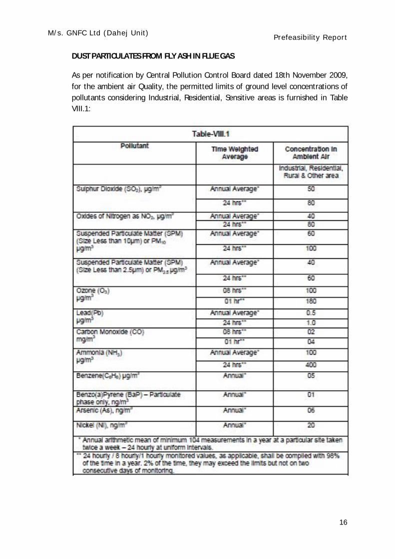
DUST PARTICULATES FROM FLY ASH IN FLUE GAS
As per notification by Central Pollution Control Board dated 18th November 2009, for the ambient air Quality, the permitted limits of ground level concentrations of pollutants considering Industrial, Residential, Sensitive areas is furnished in Table VIII.1:

M/s. GNFC Ltd (Dahej Unit) Prefeasibility Report
17
As per the above norms the particulate matter (PM) emission applicable to this project would be 50 mg/Nm3. But considering new notification of limiting the PM emission to 30 mg/Nm3 as per the stipulation by the World bank group on pollution prevention and abatement handbook (July 1998), the electrostatic precipitators (ESP) for the project would be designed to limit the emission level of PM to be within 30 mg/Nm3.
SULPHUR DIOXIDE (SO2) IN FLUE GAS
One RCC chimney having brick flue is proposed for the captive co-generation unit. The total height of chimney will be around 110m for effective dispersal of SO2. The exit velocity of flue gas from the chimney will be in the range of 22-25 m/sec.
NITROGEN OXIDES (NOX) IN FLUE GAS
Since CFBC boiler technology is adopted for this project, the NOx emission expected from the steam generator would be low. The relatively low combustion temperature in the CFBC boiler helps to reduce NOx formation. The NOx ground level concentrations (GLC) have to be verified during the EIA study.
COAL DUST PARTICLES DUE TO HANDLING OF COAL
Coal dust would be generated generally at the conveyor transfer points, coal unloading area. Hence coal transfer points would be provided with dust extraction facilities. Further, in order to arrest the coal dust generation, pipe conveyors are proposed wherever feasible and all trough type conveyors would be provided with enclosed galleries. The bottom portion of all the conveyor galleries would be provided with seal plates within the power plant area and at road crossings. The coal unloading area will be provided with plain water dust suppression system, to reduce the dust being generated during unloading operation.
Dust collection system would also be provided in coal bunkers and coal storage silos to evacuate dust and hazardous gases like methane from the coal bunkers. Collected dust would be returned to either the associated belt conveyor or to the coal bunker.
The dust collector outlet emission would be restricted to 30 mg/Nm3.

M/s. GNFC Ltd (Dahej Unit) Prefeasibility Report
18
FLY ASH DUST PARTICLES FROM ASH SILOS AND ASH DISPOSAL AREA
Fly ash evacuated from the ESP collecting hoppers would be transported in closed pipelines by pneumatic means. At the time of unloading fly ash to the silos, some ash laden air could escape out. In order to restrict the fly ash dust particles to the limits of 30 mg/Nm3, a vent filter would be installed on top of each of the fly ash silos at the vents.
In order to restrict the bottom ash dust particles to the limits of 30 mg/Nm3, a vent filter would be installed on top of each bottom ash silos at the vents.
WATER POLLUTION
The water pollutants applicable for this plant are:
a) Cooling tower blow down water
b) Steam generator blow down
c) Effluent from ash handling area
d) Effluent from coal pile area
e) Air pre-heater wash water effluent
f) Plant wash down water
g) Floor and equipment drainage effluent
h) Rain water drainage
i) Sewage from various buildings in the plant
As per the notification issued by the Ministry of Environment and Forests dated 19 May 1993, the Schedule-VI specifies the quality of effluent permitted to be discharged. The qualities of effluents have been specified under the following categories:
a) Inland surface water
b) Public sewage
c) Land for irrigation
d) Marine coastal areas.

M/s. GNFC Ltd (Dahej Unit) Prefeasibility Report
19
For the proposed power plant, the category to be considered would be under inland surface waters. The major effluent limits under category are:
a) Suspended solids: 100 mg / l (max)
b) pH: 6.5 to 8.5
c) Temperature: Shall not exceed 50C above the receiving water Temperature
d) Oil and grease: 10 mg/l.
The quantity of effluents would conform to the limits indicated above and also those limits prescribed by Gujarat Pollution Control Board (GPCB).
REUSE OF PLANT EFFLUENTS
The following measures are proposed for reusing plant effluents:
Cooling Tower Blow down
Water from CW blow down tank would be utilized for cleaning the coal handling system area and cleaning of silo area of ash handling system.
The cooling tower blow down does not require treatment but relies on minimizing the level of pollutants by operating at reduced cycles of concentration to prevent the built-up of contaminants and through proper selection of treatment chemicals
Plant Wash Down Water
In the power plant, some specific locations require washing to maintain good plant housekeeping and prevent build up of dirt and waste material. The waste water would be led to the existing ETP.
Floor and Equipment Drainage System Effluent
Means would be provided for collecting and draining water from floors in process areas of the plant and collecting and disposing of water and other liquids from process equipment, discharged fire protection water and oil storage tanks.
In the turbine building, the ground floor slabs would be sloped to drain out floor drains. The equipment drains are piped directly to the drain system. Drains are collected and directed to sumps outside the buildings from where it would be pumped to the ETP through oil water separator.

M/s. GNFC Ltd (Dahej Unit) Prefeasibility Report
20
SEWAGE FROM VARIOUS BUILDINGS IN THE PLANT
Sewage from various buildings will be by sewers connecting to the nearest manholes. The sewage will be led to existing effluent treatment plant. A network of sewers with manholes located at all junctions and at a spacing of 50 m will be provided to cover all the buildings in the proposed cogeneration facility.
THERMAL POLLUTION
The power plant envisages installation of all required heat recovery system example air heaters, economizers to utilize the heat content of the exhaust gas from the steam generator, which would enable reduction of the exhaust gas to lowest possible value there by reducing the thermal heat discharge in to atmosphere.
NOISE POLLUTION
The source of noise in the proposed power plant are:
a) Steam turbine generator
b) Other rotating equipment
c) Combustion induced noises
d) Flow induced noises
e) Steam safety valves
All the equipment in the power plant would be designed / operated to have the noise level not exceeding 85 - 90 db (A) measured at a distance of 1.5 m from the equipment. Also, all the measures would be taken to limit the noise levels at the plant boundary within the stipulated limits.
5 SITE ANALYSIS
Connectivity.
The proposed site is within premises of existing TDI Manufacturing unit, Plot no. D-II/8, Dahej-II Industrial Estate, Rahiyad; Ta: Vagra, Dist: Bharuch.
The project becomes part of eminent PCPIR launched by government for rapid industrialization and economic growth. All required infrastructure facilities; i.e, road, water and electricity are easily available. The geographic details and basic site analysis is delineated below.

M/s. GNFC Ltd (Dahej Unit) Prefeasibility Report
21
Sr. no. Criteria Details
1. Project location Inside existing premises of TDI Dahej Unit, GNFC, Dahej-II Industrial estate, Ta: Vagra, dist: Bharuch
2. Geographical coordinates of the site
Latitude : 21°41’46”N
Longitude : 72°40’06”E
3. Nearest railway station and its distance from project site
Bharuch Railway Station, about
45 km/ Dahej 10km.
4. Nearest major city and its distance from project site
Bharuch, about 34 km
5. Nearest commercial airport and its distance from project site
Vadodara, about 84 km from the site
6. Nearest highway and its distance to the site
State highway(SH-6): 2 km
National highway(NH-228): 27 km
Land Form, Land use and Land ownership.
The site is on flat land. Project proponent has already occupied this industrial land since long and has kept for future development. The land is presently in possession of project proponent.
Topography
The proposed site is on flat land with altitude 6.5 to 6.75 above MSL. The portion of toposheet no NF-42-9; showing site and it surrounding is shown as below.

M/s. GNFC Ltd (Dahej Unit) Prefeasibility Report
22
As per the seismic zoning map of India, the proposed project area falls under seismic Zone III of IS: 1893-2002. The importance factor of 1.75 would be considered for all power plant buildings/ structures as per IS: 1893-2002
6 PROPOSED INFRASTRUCTURE
The project would be set up in 37,125 m2 area within existing premises of GNFC Dahej Unit. The unit already has sufficient land in its possession land and kept this land spare for future expansion.
Looking at the availability of suitable patch of land; vicinity of water storage tank and ease of distribution, following layout have been finalized.
As the project is being set up in existing premises and existing manufacturing units already have the infrastructure facilities available, it can be utilized for propose activities as well. The propjet proponent shall also utilize existing facilities for Effluent Treatment Plant Potable water Solid waste storage area
M/s. GNFC Ltd (Dahej Unit) Prefeasibility Report
23
Common utility area like cooling tower, DM water plant and condensate polishing unit
7 REHABILITATION AND RESETTLEMENT(R & R) PLAN
As the project proponent is already in possession of the land notified as industrial land, and have already started manacling unit at selected location, there would be no requirement of displacement of personnel. Hence, Rehabilitation and Resettlement Plan is not required.
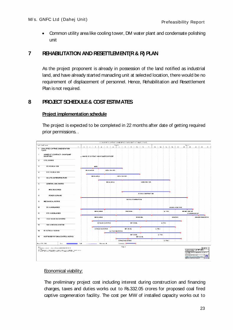
8 PROJECT SCHEDULE & COST ESTIMATES
Project implementation schedule
The project is expected to be completed in 22 months after date of getting required prior permissions. .
Economical viability:
The preliminary project cost including interest during construction and financing charges, taxes and duties works out to Rs.332.05 crores for proposed coal fired captive cogeneration facility. The cost per MW of installed capacity works out to

M/s. GNFC Ltd (Dahej Unit) Prefeasibility Report
24
Rs.18.89 crores for the cogeneration facility having a gross power output at generator terminal of 18000 kW.
The levelised cost of power and process steam generation from the proposed coal fired captive cogeneration facility after allowing for auxiliary power consumption works out to Rs.6.13/kWh and Rs 1300/ton respectively.
Considering the investment cost and the cost savings by operating the cogeneration plant against the present arrangement of meeting process steam from natural gas fired boiler and power purchase from the grid, the internal rate of return (IRR) and payback period arrives at 28.1% and 1 year respectively.

M/s. GNFC Ltd (Dahej Unit) Prefeasibility Report
25
Annexure-I
COAL ANALYSIS REPORT

M/s. GNFC Ltd (Dahej Unit) Prefeasibility Report
26
TAR ANNALYSIS REPORT

M/s. GNFC Ltd (Dahej Unit) Prefeasibility Report
27
NG Analysis