PREFEASIBILITY PROJECT REPORTPREFEASIBILITY PROJECT REPORT...
14
MCFL PPR Page 1 of 14 PREFEASIBILITY PROJECT REPORT PREFEASIBILITY PROJECT REPORT PREFEASIBILITY PROJECT REPORT PREFEASIBILITY PROJECT REPORT (PPR) (PPR) (PPR) (PPR) ON 1 MILLION t/y DAP / NPK PROJECT JUNE 2016 MANGALORE CHEMICALS & FERTILIZERS LIMITED PANAMBUR, MANGALORE – 575 010
Transcript of PREFEASIBILITY PROJECT REPORTPREFEASIBILITY PROJECT REPORT...

MCFL PPR Page 1 of 14
PREFEASIBILITY PROJECT REPORTPREFEASIBILITY PROJECT REPORTPREFEASIBILITY PROJECT REPORTPREFEASIBILITY PROJECT REPORT
(PPR)(PPR)(PPR)(PPR)
ON
1 MILLION t/y DAP / NPK PROJECT
JUNE 2016
MANGALORE CHEMICALS & FERTILIZERS LIMITED
PANAMBUR, MANGALORE – 575 010

MCFL PPR Page 2 of 14
1) PREAMBLE
Mangalore Chemicals & Fertilizers Ltd (MCF) is an 'Adventz' Group Company, a large and
diversified business house. The main products of MCF are Urea, Di-Ammonium Phosphate (DAP),
NP 20:20:00:13, Ammonium Bi-Carbonate (ABC) - Food grade, Sulphuric Acid, Specialty Mixtures
of Plant Nutrients consisting of Water Soluble Fertilizers, Micronutrients & Soil Conditioners and
an Industrial Product called Sulphonated Naphthalene Formaldehyde (SNF) used in construction
industry.
MCF is the only manufacturer of chemical fertilizers in the state of Karnataka. The factory is
strategically located at Panambur, 9 km north of Mangalore City, on the banks of the Gurpur River,
along the National Highway 66, opposite to the New Mangalore Port Trust. MCF is an ISO 14001,
OHSAS 18001 and ISO 22000 certified Company.
The main products are Urea, Di-Ammonium Phosphate (DAP), NP 20:20:00:13, Ammonium Bi-
Carbonate (ABC) - Food grade, Sulphuric Acid, Speciality mixtures of plant Nutrients consisting of
Water Soluble Fertilizers, Micronutrients & Soil Conditioners and an Industrial Product called
Sulphonated Naphthalene Formaldehyde (SNF) used in construction industry.
While fertilizers and Plant nutrient products are marketed in all the Southern States and
Peninsular India, the food grade ABC, which is used mainly in Confectionery Industries is marketed
in domestic as well as international market. The requirement of power for the production facility
(process plants) is met by a Captive Power Plant. Ammonia & Phosphoric Acid, the raw materials
required for DAP & NP production are imported.

MCFL PPR Page 3 of 14
The consented capacity for the intermediates and products manufactured are as below:
Sl. No. Product t/y
1 Ammonia 2,40,900
2 Urea 4,19,750
3 DAP & NP (16:20 & 20:20) 4,01,500
4 Ammonium Bicarbonate (ABC) 24,750
5 Sulphuric Acid 1,46,000
6 Sulphonated Naphthalene Formaldehyde 85,000
7 Speciality mixtures of plant nutrients 2,21,000
8 Handling of imported fertilizers 4,00,000
Construction of Ammonia and Urea plants commenced in 1972 and commercial production
started in 1976. Di-ammonium Phosphate (DAP) production commenced during 1986.
Commercial production of Ammonium Bicarbonate started in 1982. Sulphuric Acid Plant was
commissioned during March 2006. Captive Power Plant consisting of 8 Diesel Generators of 6
MW each were commissioned during 1986. The power plant has been revamped in 2012-2014.
A new construction chemical product Sulphonated Naphthalene Formaldehyde facility was
installed in 2010 as part diversification. MCF also has installed a Speciality fertilizer plant to make
Water Soluble Fertilizers & Micronutrients in 2011.
MCF Intends to expand the present facilities in existing location at Mangalore by putting up
1 million t/y DAP / NPK Project.

MCFL PPR Page 4 of 14
2) NEED FOR THE PROPOSED PROJECTS
1 Million t/y DAP/NPK Plant. : DAP/NPK Fertilizer Complex is an important area of fertilizer
segment. India is the third largest producer and second largest user of DAP/NPK and has one
of the largest areas under Irrigation. Complex Fertilizers includes DAP (Di Ammonium
Phosphate) and NPK Fertilizers. There is huge demand of Phosphatic fertilizers in the
country. India has produced, 10.5 million tonnes of DAP/NPK during 2013-14 and imported
6.7 million tonnes of DAP/NPK. In India, DAP is the major product contributing 63% of the
total phosphate consumption. The estimated total demand supply gap by 2015-2016 would
be 11 Million MT of DAP alone. DAP & NPK fertilizers are in great demand and there is huge
gap between availability and supply. India is a net importer of DAP & NPK fertilizers.
DAP/NPK is an important fertilizer and Government of India is bound to support this industry
through conducive policies/subsidies. All southern states of India namely Karnataka,
Tamilnadu, Kerala and Andhra Pradesh have enough demand for DAP/NPK fertilizers.
MCF intends to put a unit of DAP/NPK along with associated facilities. Bagging plant, bulk
silo, raw material storages, offsite and utilities etc. are part of associated facilities.
This is an expansion brown field project. Accordingly, required site infrastructure and utilities
are available. MCF has vacant land of about 50 acres in the existing fertilizer complex and
layout is developed. The present fertilizer complex is located in Baikampady Industrial Estate
notified by Karnataka Industrial Area Development Board, (KIADB) Karnataka. The site is well
connected and has advantage of good infrastructure facilities like roads, water, power,
effluent treatment facilities and good green belt.
The site selected for the project is currently available at the premises of MCF, which makes
integration of utilities like power and steam generation with existing fertilizer plant very cost
effective. The geographical proximity of the plant with the New Mangalore Port offers
excellent logistic advantage for import of raw material with cost advantage.
Existing infrastructure will be most optimally used resulting in increase of productivity of
existing operations as well as reduction of overall cost of new project. Further the impact on
environment will be minimal compared to the project being set up on a new green field site.

MCFL PPR Page 5 of 14
3.1) DAP/NPK PLANT
NH3 + H3PO4 --------------> NH4H2PO4 + Q2A
(Ammonia) (Phosphoric Acid) (Mono-ammonium Phosphate)
NH4H2PO4 + NH3 --------------> (NH4)2HPO4 + Q2B
(Di-ammonium Phosphate) (Ammonia) (Di-ammonium Phosphate)
a) Dry Section
With reference to the simplified process flow diagram for the Dry Section of the Slurry Process, a
detailed description is furnished as follows:

MCFL PPR Page 6 of 14
Phosphoric acid, gaseous Ammonia, and scrubber liquor enter into the Preneutralizer where it is
controlled at a specific gravity of 1.53 and a mole ratio of 1.5, which corresponds to moisture
content in the slurry of 18%. The Preneutralizer is maintained at a mole ratio of 1.5 to ensure
maximum solubility of the slurry. The Ammonium Phosphate slurry is pumped from the
Preneutralizer to the Pipe Reactor where it is combined with strong phosphoric acid, and gaseous
Ammonia and sprayed onto the bed of the Rotary Granulator at a mole ratio of 1.5 and moisture
of 10%. Underneath the bed in the Granulator is the Ammonia sparger that supplies liquid
Ammonia to raise the mole ratio of the fertilizer up to the desired value.
The material leaves the Granulator and enters into the Rotary Dryer where the DAP is dried, using
hot gases leaving the Combustion Chamber, to a moisture of 1.0-1.5% or even lower if needed.
After exiting the Dryer the material enters into the Primary Elevator to be distributed over the
Oversize Screens. The Oversize Screens are double deck screens where the oversize is sent to the
chain mills, the undersize falls onto the Recycle Belt along with the crushed material, and the
product size material is sent to the Product Screen Elevator for distribution on the Product
Screens.
The purpose of the Product Screens is to remove the remaining fines that were not removed by
the Oversize Screens. The fines fall onto the Recycle Belt and the on spec material enters into the
Fluidized Bed Cooler or is recycled for control of the recycle ratio. The air entering into the
Fluidized Bed Cooler can be chilled using the Ammonia Air Chiller which will be discussed later.
Once leaving the Fluidized Bed Cooler the material enters into the Product Elevator and is
distributed onto the Polishing Screens. The on spec material then enters into the Coating Drum
and is then conveyed to the storage building. The gases leaving the Dryer, Product Cooler, and
Dedusting system are each sent through a separate set of cyclones. After the dedusting system
offgas exits the cyclones it is sent through a baghouse to be sent to the Combustion Chamber.
If this method of recycling dedusting offgases is not in place then the gases are sent to the RG
Scrubber. The gases leaving the Dryer Cyclones go to the Dryer Scrubber and the gases leaving
the Cooler Cyclones go the Tail Gas Scrubber.
MCFL PPR Page 7 of 14
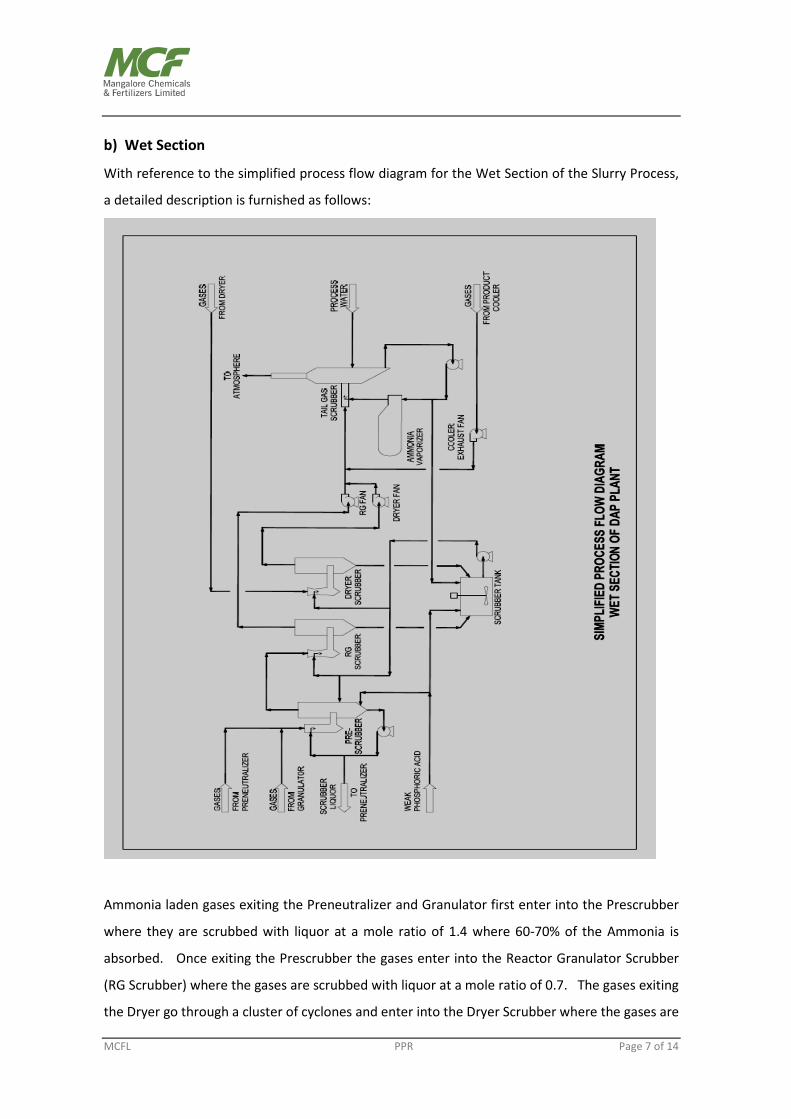
b) Wet Section
With reference to the simplified process flow diagram for the Wet Section of the Slurry Process,
a detailed description is furnished as follows:
Ammonia laden gases exiting the Preneutralizer and Granulator first enter into the Prescrubber
where they are scrubbed with liquor at a mole ratio of 1.4 where 60-70% of the Ammonia is
absorbed. Once exiting the Prescrubber the gases enter into the Reactor Granulator Scrubber
(RG Scrubber) where the gases are scrubbed with liquor at a mole ratio of 0.7. The gases exiting
the Dryer go through a cluster of cyclones and enter into the Dryer Scrubber where the gases are

MCFL PPR Page 8 of 14
scrubbed with the same liquor that is used in the RG Scrubber. The liquor that is used in the RG
Scrubber and the Dryer Scrubber is circulated from the Scrubber Tank. Gases from the RG
Scrubber and Dryer Scrubber along with the gases that exit the Cooler Cyclones enter into the Tail
Gas Scrubber and then exit into the atmosphere. The circulating liquor in the Tail Gas Scrubber
is sent through a kettle type heat exchanger to vaporize Ammonia.
c) Pipe Reactor used in conjunction with Preneutralizer
The purpose of the Pipe Reactor is to supply Ammonium Phosphate slurry at a low moisture
content thereby reducing fuel requirements in the drying step. The Pipe Reactor mixes high
strength Phosphoric acid, gaseous anhydrous Ammonia, and reactor slurry from the
Preneutralizer and sprays it onto the bed of the Granulator. The reason the Pipe Reactor can
operate at such a low moisture is because of the high temperature and pressure which keeps the
slurry fluid. Under atmosphere pressure the slurry reaches a minimum moisture content of 18%
and in the Pipe Reactor it can be as low as 10%. The moisture content in the Pipe Reactor is
reduced by vaporizing water from the high heat of reaction of Phosphoric acid and Ammonia.
Another reason why the Pipe Reactor is economical is because it reduces Citrate Insoluble P2O5.
Citrate Insoluble P2O5 increases with increased retention time and since the retention time of a
Pipe Reactor is very low there is virtually no Citrate Insoluble P2O5 produced in the Pipe Reactor.
The average Citrate Insoluble P2O5 can be reduced by 0.2% when a Pipe Reactor is used. The
Preneutralizer mixes Phosphoric acid, Ammonia, and Scrubber liquor to be sent to the Pipe
Reactor or directly to the Granulator. The Phosphoric acid and Scrubber liquor are fed through
the top of the reactor while the gaseous anhydrous Ammonia is fed through spargers located at
the bottom.
The process uses the reduced retention time Preneutralizer where the diameter at the bottom of
the tank is smaller than the top. The advantage of this design is that the Citrate Insoluble losses
are decreased while still maintaining the liquid level necessary to absorb Ammonia and not to
entrain liquid in the exiting gas. The Citrate Insoluble losses increase with increased retention
time so it is necessary to minimize the liquid volume in the Preneutralizer. The Preneutralizer is
much simpler to operate than the Pipe Reactor and when used in conjunction with the Pipe
Reactor it gives the plant a stable baseline and increased controllability.

MCFL PPR Page 9 of 14
Using a Preneutralizer reduces the amount of water that is vaporized in the Granulator by the
Pipe Reactor. If less water is vaporized in the Granulator then less air is needed to keep the gas
leaving the Granulator below the saturation point. For a 120 MT/hr. plant, the required airflow in
the Granulator when a Pipe Reactor and Preneutralizer are installed is 44,000 ACFM and when
there is only a Pipe Reactor present is 88,000 ACFM. This reduced airflow reduces the size of the
Granulator, Prescrubber, RG Scrubber, RG Fan, Scrubber Pump and the Tail Gas Scrubber and
Pump.
d) Dual Mole Scrubbing
Dual Mole Scrubbing is a two stage process where gases from the Preneutralizer and Granulator
are scrubbed with a high N/P mole ratio liquor followed by scrubbing at a low mole ratio. The
gases first enter the Prescrubber, which operates at a mole ratio of 1.4, where about 60-70% of
the Ammonia is removed. Next the gases enter into the Reactor Granulator (RG) Scrubber where
the rest of Ammonia as well as the fluorine are removed and this scrubber operates at a mole
ratio of 0.7.
MCFL PPR Page 10 of 14
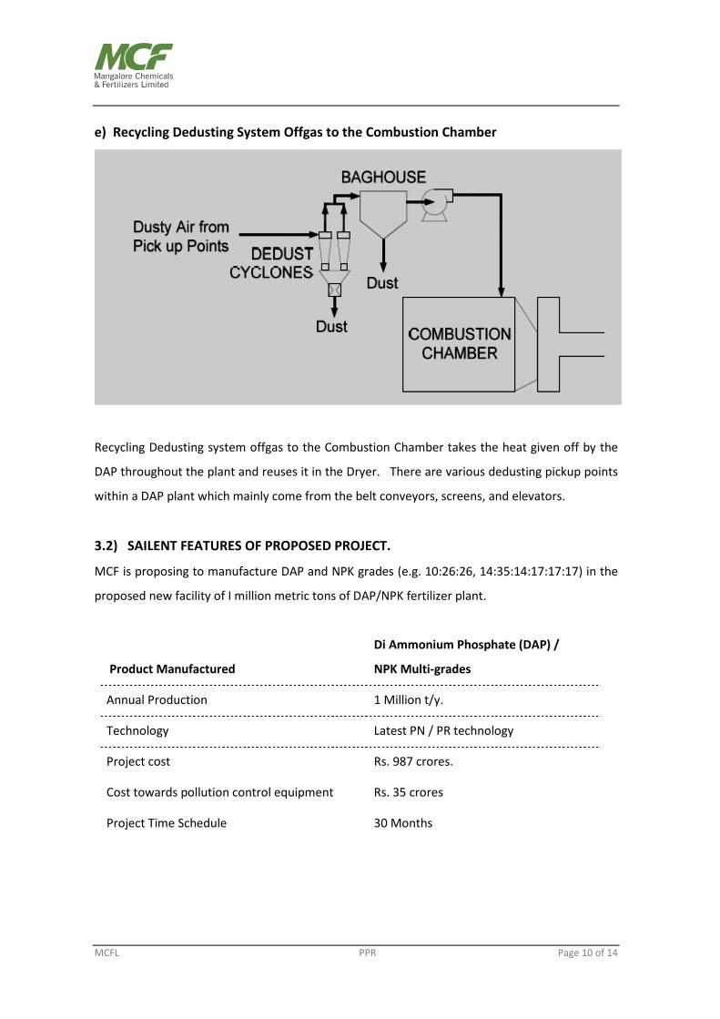
e) Recycling Dedusting System Offgas to the Combustion Chamber
Recycling Dedusting system offgas to the Combustion Chamber takes the heat given off by the
DAP throughout the plant and reuses it in the Dryer. There are various dedusting pickup points
within a DAP plant which mainly come from the belt conveyors, screens, and elevators.
3.2) SAILENT FEATURES OF PROPOSED PROJECT.
MCF is proposing to manufacture DAP and NPK grades (e.g. 10:26:26, 14:35:14:17:17:17) in the
proposed new facility of I million metric tons of DAP/NPK fertilizer plant.
Product Manufactured
Di Ammonium Phosphate (DAP) /
NPK Multi-grades
Annual Production 1 Million t/y.
Technology Latest PN / PR technology
Project cost Rs. 987 crores.
Cost towards pollution control equipment Rs. 35 crores
Project Time Schedule 30 Months

MCFL PPR Page 11 of 14
Annual Requirement of Raw Materials and Utilities
Ammonia 160000 MT
Phosphoric acid (100% P2O5) 334000 MT
Muriate of Potash (MOP) 277000 MT
Sulphuric acid 33000 MT
Furnace Oil 6500 MT
No trade effluent generation from the proposed DAP/NPK plant. No solid waste will be
generated. Any spillage will be recycled and reused in the proposed plant. There will not be any
additional water drawl from the Mangalore City Corporation due to requirement of proposed
project. The marginal increase in the water requirement after the commissioning of DAP/NPK
plant will be met by effluent water recovery unit installed.
4) ENVIRONMENTAL MANAGEMENT
DAP/NPK Plant
The proposed project will not have any significant adverse impact on the existing environment as
sufficient pollution control measures are incorporated in the process technology and plant
design. The technology also incorporates special scrubbing equipment like Dual Mole Scrubbing
System and also Dedusting system. In DAP / NPK plant Air pollution control equipment viz.
Cyclone, Scrubber, Mist eliminator etc. shall be installed during the commissioning of the plant
itself.
There will be no liquid waste and solid waste generation from the plant. All liquid spillages shall
be collected and recycled back to the process.
The flow of gaseous emission from the stack (47 m) is expected to be maximum of
688000 Nm3/hr., particulate Matter 150 Mg/Nm3, fluorine 20mg/Nm3 and Ammonia 300mg/Nm3.

MCFL PPR Page 12 of 14
Since no liquid effluent and solid waste will be discharged from the plant there will not be any
significant adverse impact on the aquatic ecosystem. The vegetation and aquatic systems of the
area will be protected by adopting the above environmental protection measures.
5) Waste Water Recovery Plant at MCF.
As corporate social responsibility, with the aim of .reusing the entire treated effluent and to
achieve the target of zero effluent discharge MCF has installed Waste Water Recovery Units
during 2009-2010 by investing about Rs. 7.0 crores for treating the effluent streams consisting of
the following:
1. Sand filter back wash water from water treatment plant and cooling tower
2. Water treatment plant resin regeneration effluent - acidic and alkaline
3. Cooling tower blow down.
4. Domestic effluent
Based on the characteristics of the effluent streams, trade effluents are categorized and is
treated as given below:
1. Sand filter back wash water from water treatment plant and cooling tower containing high
suspended solids effluent is treated by using. Lamella Clarifier technology.
Static mixer, Lamella clarifier, centrifuge and sand filter are major equipment for treating the high
suspended solids effluent streams. Back wash water of sand filter and activated carbon filter
from water treatment plant and cooling 'tower side stream filter are treated in this unit. The
treated water is reused in cooling tower as makeup. The slurry containing solids is pumped to a
centrifuge for separating liquid which is recycled to static mixer. The thickened slurry is used in
DAP plant.
2. Water treatment plant resin regeneration and cooling tower blow down effluents
containing high dissolved solids is treated by Reverse Osmosis technology.
The high dissolved solids effluent stream containing water treatment plant resin regeneration
effluent and cooling 'tower blow down is passed through clarifier, pressure sand filter and Ultra
Filtration (UF) units to remove suspended solids and colloidal particles. Then it is treated in

MCFL PPR Page 13 of 14
Reverse Osmosis (RO) units to remove dissolved solids. Treated water is reused in cooling tower
as makeup.
The high dissolved solids effluent streams are collected in an equalization tank. This stream after
dosing with NaOCI, Coagulant, Lime, Dolomite & Polymer is pumped to High Rate Solids Contact
Clarifier (HRSCC). The clarified water from HRSCC is passed through Multi Grade' filter for
reduction of suspended solids.
Then the filtered water is fed into the Ultra filtration unit (UF) to remove colloidal silica and related
colloids of iron and aluminium in water causing fouling, scaling and poor performance of the plane
the stream which is free from suspended and colloidal particles will be passed through Reverse
Osmosis unit (RO). The Dissolved solids are removed in 2 stages of RO unit. In the first stage R01
about 75 % of desired quality water will be recovered and reject is fed to second stage R02 wherein
further 10% is recovered. The R02 reject containing high dissolved solids is used in DAP plant.
The recovered water is used in cooling tower as makeup. The sludge collected in the HRSCC is
pumped to centrifuge to remove water. The separated liquid is recycled to equalizing tank and
thickened slurry is used in DAP plant.
6) Sewage Treatment Plant:
The domestic effluent generated due to new 1 million ton DAP/NPK & PCE complex also shall be
collected and treated at existing sewage treatment plant (STP). The details of the existing STP is
given below:
MCF has put up a centralized sewage treatment unit. The combined sewage from the factory is
collected in the sump tanks and pumped to the bar screen chamber and oil trap to remove
floating solids and oil traces respectively. After this preliminary treatment the effluent is fed to
equalization tank.
Effluent from the equalization tank is fed to the Membrane Bio-Reactor (MBR) tank at constant
flow rate. The high amount of bacteria gives better and complete removal of organic matter from
the raw effluent in relatively small area. Aeration is done both to the equalization and MBR tanks
through diffuser membranes by using blowers.
MCFL PPR Page 14 of 14
The suction pumps directly sucks permeate and the filtration is carried out by the membrane.
The suspended solids, turbidity, bacteria and viruses in permeate water are removed to the levels
required for reusing treated water. The treated water is reused in cooling tower as makeup.
By installation of the above wastewater treatment plants with latest technologies, MCF has
achieved the aim of reusing the entire treated wastewater and the target of zero wastewater
discharge.
7) Green Belt
MCF has already developed and maintained a green belt covering an area of about 64 acres.
The green belt contains around 60,000 trees of different species viz. Mangium, Casurina,
Subabul, Acacia, Gulmohar, Jack, Cashew, Mango, Banyan, Peepal, etc.
-------------------- x ---------------------