Preface, Contents Systems 1 SIMATIC 2 3 SFC for …...SFC for S7 A5E00177375-01 iii Preface Purpose...
122
Preface, Contents Basics of Sequential Control Systems 1 Working with the SFC Editor 2 Sequential Control System on the AS 3 Test and Startup 4 Documentation 5 Appendix Technical Specifications A Abbreviations B Glossary, Index SIMATIC SFC for S7 Sequential Function Chart Manual Edition 01/2003 A5E00177375-01 12.03.2003 17.02.2003 17.02.2003 17.02.2003
Transcript of Preface, Contents Systems 1 SIMATIC 2 3 SFC for …...SFC for S7 A5E00177375-01 iii Preface Purpose...
Preface, Contents
Basics of Sequential ControlSystems 1
Working with the SFC Editor 2Sequential Control Systemon the AS 3
Test and Startup 4
Documentation 5
Appendix
Technical Specifications A
Abbreviations BGlossary, Index
SIMATIC
SFC for S7Sequential Function Chart
Manual
Edition 01/2003A5E00177375-01
12.03.200317.02.200317.02.200317.02.2003

Copyright © Siemens AG 2003 All rights reserved
The reproduction, transmission or use of this document or itscontents is not permitted without express written authority.Offenders will be liable for damages. All rights, including rightscreated by patent grant or registration of a utility model or design,are reserved.
Siemens AGBereich Automation and DrivesGeschaeftsgebiet Industrial Automation SystemsPostfach 4848, D- 90327 Nuernberg
Disclaimer of Liability
We have checked the contents of this manual for agreement withthe hardware and software described. Since deviations cannot beprecluded entirely, we cannot guarantee full agreement. However,the data in this manual are reviewed regularly and any necessarycorrections included in subsequent editions. Suggestions forimprovement are welcomed.
©Siemens AG 2003Technical data subject to change.
Siemens Aktiengesellschaft A5E00177375-01
Safety Guidelines
This manual contains notices intended to ensure personal safety, as well as to protect the products and
connected equipment against damage. These notices are highlighted by the symbols shown below and
graded according to severity by the following texts:
! Dangerindicates that death, severe personal injury or substantial property damage will result if properprecautions are not taken.
! Warningindicates that death, severe personal injury or substantial property damage can result if properprecautions are not taken.
! Cautionindicates that minor personal injury can result if proper precautions are not taken.
Cautionindicates that property damage can result if proper precautions are not taken.
Noticedraws your attention to particularly important information on the product, handling the product, or to aparticular part of the documentation.
Qualified Personnel
Only qualified personnel should be allowed to install and work on this equipment. Qualified persons are
defined as persons who are authorized to commission, to ground and to tag circuits, equipment, and
systems in accordance with established safety practices and standards.
Correct Usage
Note the following:
! WarningThis device and its components may only be used for the applications described in the catalog or the
technical description, and only in connection with devices or components from other manufacturers
which have been approved or recommended by Siemens.
This product can only function correctly and safely if it is transported, stored, set up, and installedcorrectly, and operated and maintained as recommended.
Trademarks
SIMATIC®, SIMATIC HMI® and SIMATIC NET® are registered trademarks of SIEMENS AG.
Third parties using for their own purposes any other names in this document which refer to trademarks might
infringe upon the rights of the trademark owners.
12.03.200317.02.200317.02.200317.02.2003

SFC for S7A5E00177375-01 iii
Preface
Purpose of the ManualThis manual supports you when you create sequential control systems andparameter controls. It provides you with an overview of the following:
• The basics of sequential control systems
• Working with the SFC Editor
• Sequential control systems on the programmable controller
• Putting sequential control systems into operation and monitoring and testingthem
• Documenting SFC charts
You will find a detailed description of the software and procedures in theSFC online help.
This manual "SFC for S7" provides you with the information you require to use theSFC configuration tool in conjunction with CPUs in SIMATIC S7 programmablecontrollers (PLCs). If you use other target systems (for example, SIMADYN D),please read the additional documentation for this target system.
How Sections for Specific Systems are IndicatedIf sections, paragraphs or even individual sentences in this S7 manual relate solelyto S7 users, this is indicated by [S7]. This means that the information is relevantonly to S7 or is different in other systems. In this case, if you use a different PLC,you will find the information you require in the manual for your specific system.If the [S7] label is in a title, the entire section applies only to S7; if the label is at thestart of a paragraph, the paragraph is solely relevant to S7. In lists, the [S7] labelapplies only to the particular list.
AudienceThis manual is intended for personnel involved in configuring, commissioning, andservice.Basic experience of working with PCs and Windows is assumed.
ValidityThis manual is valid for the SFC software version V6.0 or higher.You will find the latest information that could no longer be included in this manualalong with instructions on installation in the README.TXT file accompanying theproduct.
12.03.200317.02.200317.02.200317.02.2003

Preface
SFC for S7iv A5E00177375-01
StandardThe SFC software is based on the international standard DIN EN 61131-3(IEC 1131-3) for programming languages for programmable logic controllers.
Further Support
If you have questions about using the products described in the manual and youcannot find the answers here, please contact your local Siemens representative.
http://www.siemens.com/automation/partner
Training CenterTo help you to become familiar with working with S7 PLCs, we offer a range ofcourses. Please contact your regional training center or the central training centerin D 90327 Nuremberg.
Phone: +49 (911) 895-3200.
Internet: http://www.sitrain.com
12.03.200317.02.200317.02.200317.02.2003

Preface
SFC for S7A5E00177375-01 v
A&D Technical Support
Open round the clock, worldwide:
Peking
Nürnberg
Johnson City
Worldwide (Nuremberg)
Technical Support
Local time: 0:00 to 24:00 / 365 days
Phone: +49 (0) 180 5050-222
Fax: +49 (0) 180 5050-223
E-mail: [email protected]
GMT: +1:00
Europe / Africa (Nuremberg)
Authorization
Local time: Mo.-Fr. 8:00 to 17:00
Phone: +49 (0) 180 5050-222
Fax: +49 (0) 180 5050-223
E-mail: [email protected]
GMT: +1:00
United States (Johnson City)
Technical Support andAuthorization
Local time: Mo.-Fr. 8:00 to 17:00
Phone: +1 (0) 423 262 2522
Fax: +1 (0) 423 262 2289
E-mail: simatic.hotline@
sea.siemens.com
GMT: -5:00
Asia / Australia (Peking)
Technical Support andAuthorization
Local time: Mo.-Fr. 8:30 to 17:30
Phone: +86 10 64 75 75 75
Fax: +86 10 64 74 74 74
E-mail: adsupport.asia@
siemens.com
GMT: +8:00
Technical Support and Authorization speak German and English.
12.03.200317.02.200317.02.200317.02.2003

Preface
SFC for S7vi A5E00177375-01
Service & Support on the InternetIn addition to our documentation services, you can also make use of all ourknowledge on the Internet.
http://www.siemens.com/automation/service&support
Here, you will find:
• The Newsletter that keeps you constantly up to date with the latest informationon the products you use.
• The documents you need using the search functions in Service & Support.
• A Forum in which users and specialists exchange information and experience.
• Your local contact for Automation & Drives in our contacts database.
Information on local service, repairs, and spare parts. Much more under theheading "Services".
12.03.200317.02.200317.02.200317.02.2003

SFC for S7A5E00177375-01 vii
Contents
1 Basics of Sequential Control Systems 1-1
1.1 General Information on Sequential Control Systems........................................1-11.2 SFC in the STEP 7 Environment ......................................................................1-21.2.1 SFC and the Plant Hierarchy [S7] .....................................................................1-31.3 Steps in Configuration.......................................................................................1-31.4 Creating the Project Structure...........................................................................1-41.5 Creating Sequential Control Systems ...............................................................1-51.6 SFC Type, SFC Instance, and External View of the Chart ...............................1-71.7 SFC Elements ...................................................................................................1-91.7.1 What is a Sequencer?.......................................................................................1-91.7.2 What are Sequence Path Elements?..............................................................1-101.7.3 What is a Step?...............................................................................................1-111.7.4 What is a Transition? ......................................................................................1-121.7.5 What is a Text? ...............................................................................................1-121.7.6 What is a Sequence and What is a Sequencer? ............................................1-131.7.7 What is a Simultaneous Sequence? ...............................................................1-141.7.8 What is an Alternative Sequence?..................................................................1-151.7.9 What is a Loop? ..............................................................................................1-161.7.10 What is a Jump? .............................................................................................1-17
2 Working with the SFC Editor 2-1
2.1 Working with Charts, Types, and Instances......................................................2-12.1.1 How to Create a Chart ......................................................................................2-12.1.2 [S7] Creating an SFC Type...............................................................................2-22.1.3 [S7] Creating an SFC Instance .........................................................................2-22.1.4 Opening a Chart or Type...................................................................................2-32.1.5 [S7] Opening an SFC Instance .........................................................................2-32.1.6 Copying Charts .................................................................................................2-32.1.7 [S7] Copying and Moving SFC Types...............................................................2-32.1.8 [S7] Copying and Moving SFC Instances .........................................................2-42.1.9 Deleting Charts and Types................................................................................2-42.1.10 [S7] Deleting SFC Instances .............................................................................2-42.1.11 Representation and Interconnection of the External View................................2-52.2 Properties of Charts and Types ........................................................................2-62.2.1 Adapting Chart Properties.................................................................................2-62.2.2 [S7] Adapting Type Properties ..........................................................................2-62.2.3 [S7] Adapting Instance Properties ....................................................................2-72.3 The Run-Time Properties..................................................................................2-82.3.1 Run Sequence...................................................................................................2-82.3.2 Run-Time Groups..............................................................................................2-92.4 Configuring Sequential Control Systems ........................................................2-112.4.1 Creating the Sequencer Topology ..................................................................2-122.4.2 Configuring Several Sequencers ....................................................................2-13
12.03.200317.02.200317.02.200317.02.2003

Contents
SFC for S7viii A5E00177375-01
2.5 Creating SFC Elements ..................................................................................2-152.5.1 Creating a Sequence ......................................................................................2-152.5.2 Creating and Extending a Simultaneous Sequence .......................................2-162.5.3 Creating and Extending an Alternative Sequence ..........................................2-172.5.4 Creating a Loop...............................................................................................2-182.5.5 Creating a Jump..............................................................................................2-192.5.6 Creating and Editing Text Objects ..................................................................2-202.6 Editing SFC Elements .....................................................................................2-212.7 Editing in the Object Properties Dialog ...........................................................2-222.7.1 Editing Object Properties: Step.......................................................................2-222.7.2 Edit Object Properties: Transition ...................................................................2-252.8 [S7] Creating an SFC Type .............................................................................2-282.9 [S7] Configuring in the Characteristics Dialog ................................................2-302.10 [S7] The I/O Groups ........................................................................................2-322.11 [S7] Configuring Messages .............................................................................2-332.12 Compiling and Downloading ...........................................................................2-342.12.1 Compile ...........................................................................................................2-352.12.2 [S7] Downloading ............................................................................................2-372.13 [S7] Parameter-Controlled Operation..............................................................2-39
3 Sequential Control System on the AS 3-1
3.1 General..............................................................................................................3-13.2 How the SFC Runs ...........................................................................................3-23.2.1 [S7] Mode ..........................................................................................................3-23.2.2 [S7] Step Control Mode.....................................................................................3-23.2.3 Chart Execution Options ...................................................................................3-33.3 How the Sequential Control System Behaves during Operation ......................3-43.3.1 [S7] The Operating States.................................................................................3-53.3.2 Operating State Logic for SFC (SFC-OSL).......................................................3-63.3.3 Operating State Logic for Sequencers (sequencer OSL) .................................3-83.3.4 Commands......................................................................................................3-103.3.5 Sequencer Execution ......................................................................................3-113.3.6 Starting an SFC (chart or instance).................................................................3-143.3.7 Execution of a Sequential Control System......................................................3-15
4 Test and Startup 4-1
4.1 Activating the Test.............................................................................................4-14.2 Display in the Test Mode...................................................................................4-34.3 Operator Control and Monitoring of the Sequential Control System.................4-64.3.1 The Object Properties of a Step during Testing................................................4-74.3.2 The Object Properties of a Transition during Testing .......................................4-9
5 Documentation 5-1
5.1 Printing an SFC.................................................................................................5-15.2 Defining Footers ................................................................................................5-25.3 Chart Reference Data .......................................................................................5-25.4 Logs...................................................................................................................5-3
12.03.200317.02.200317.02.200317.02.2003
Contents
SFC for S7A5E00177375-01 ix
A Technical Specifications A-1
A.1 Technical Specifications................................................................................... A-1
B Abbreviations B-1
Glossary
Index
12.03.200317.02.200317.02.200317.02.2003

Contents
SFC for S7x A5E00177375-01
12.03.200317.02.200317.02.200317.02.2003

SFC for S7A5E00177375-01 1-1
1 Basics of Sequential Control Systems
IntroductionThis chapter explains the basics of sequential control systems.
Here, you will learn what a sequential control system is and what it is used for. Youwill get to know the terminology and elements of SFC and the rules governing thetopology of sequencers.
1.1 General Information on Sequential Control Systems
What is SFC?An SFC chart, an SFC type, or an SFC instance is a sequential control system.The SFC editor is a tool with which you can create a sequential control systemintegrating several sequencers that can be started separately.
In these descriptions, the term “SFC" is used to mean a chart, a type, an instance,or the SFC editor depending on the context.
An SFC chart is assigned uniquely to a CPU and is also executed completely onthis CPU. Instances of a type can exist on several CPUs.
What is a sequential control system?A sequential control system is a controller partitioned to ensure step-by-stepexecution with control passing from one state to the next state dependent onconditions.
Sequential control systems can be used, for example, to describe the manufactureof products as event-controlled processes (recipes).
With a sequential control system, functions from basic control (typically createdwith CFC) are controlled by mode and state changes and executed selectively.
17.02.200317.02.200317.02.2003

Basics of Sequential Control Systems
SFC for S71-2 A5E00177375-01
Where are sequential control systems used?The typical applications of sequential control systems involve processes and plantswith discontinuous characteristics. Sequential control systems can, nevertheless,also be used for continuous processes and plants, for example for approach andwithdrawal movements, operating point changes, and state changes due to faultsetc.
[S7] Such systems can be used at various levels of a process or plant:
• Device control level (open valve, start motor .....)
• Group control level (proportioning, stirring, heating, filling .....)
• Unit level ( tank, mixer, scales, reactor .....)
• Plant level (synchronization of units and commonresources, for example routing)
1.2 SFC in the STEP 7 Environment
The SIMATIC Manager is used for all ASs as the central database to coordinatethe tools and objects. It manages the tools and data and is used to create andmodify a project structure (CPU, CFC/SFC charts) and to start the SFC editor.
Figure 1-1 shows how SFC fits into the STEP 7 and PCS 7 environment:
CFC
SIMATIC Manager
STEP 7
SFC
STEP 7 tool
WinCCPH IEA
SFCVisuali-zation
OSPLCPCS 7
PO
Figure 1-1: SFC in the STEP 7 / PCS 7 Environment
Legend: PH (Plant Hierarchy), IEA (Import/Export Assistant) and PO (ProcessObject view) are components of the Process Control System (PCS 7) and extendthe SIMATIC Manager. WinCC is the operator control and monitoring system inPCS 7.
17.02.200317.02.200317.02.2003

Basics of Sequential Control Systems
SFC for S7A5E00177375-01 1-3
1.2.1 SFC and the Plant Hierarchy [S7]
The plant hierarchy (PH) allows charts to be arranged and managed not only fromthe point of view of running them on a CPU, but also according to technological orplant criteria (for example an SFC chart for device control, group control, or unitcontrol).
If the SFC chart was assigned to a plant hierarchy folder, the path of the planthierarchy is added to the chart name. You can use the naming scheme of yourplant as the criteria for arranging charts in the project.
For more detailed information on the plant hierarchy, refer to the online help of PH.
1.3 Steps in Configuration
How the Editor Works
Using the SFC editor, you create your sequential control system using graphictools. The elements of the SFC are positioned according to fixed rules in thesequencer. You do not need to be aware of details such as algorithms or theassignment of machine resources but can concentrate solely on the technologicalaspects of your configuration.
After creating the sequencer topology, you move on to configure the objectproperties where you formulate the properties of the sequencers, the individualsteps and transitions; in other words, you configure the actions and conditions.
After configuration, you compile the executable machine code with SFC, downloadit to the AS, and test it with the SFC test functions.
17.02.200317.02.200317.02.2003

Basics of Sequential Control Systems
SFC for S71-4 A5E00177375-01
1.4 Creating the Project Structure
Three alternative methods of creating a project structure are shown below:
1. Start the SIMATIC Manager and then the PCS 7 Wizard (if this is not alreadystarted automatically) by selecting "File > 'New Project' Wizard...". Workthrough the dialogs displayed by the Wizard. In the dialog "Which objects willbe used in the project?", the option "SFC chart" may be set as the default inthe "AS objects" box.
The wizard creates a single project or multiproject in the plant view and in thecomponent view. Apart from the actual project, a multiproject also includes amaster data library.During the creation of the project, certain defaults are set that you can modifylater if necessary.
2. The STEP 7 Wizard was started in the SIMATIC Manager. (The setting PCS 7or STEP 7 is made with "Options > Customize..." in the "Wizards" tab of thedialog.)Using this wizard, you create a STEP 7 project; in other words the SIMATICStation, the CPU, the S7 program and the block folder.
- Select the menu command "Insert > S7 Software > Chart Folder".Insert a chart in the chart folder.
- Select the chart folder and then the menu command "Insert > S7 Software> SFC".
3. Create a new project in the SIMATIC Manager using menu commands.
- Select "File > New...", enter the name of the project in the dialog box andconfirm with "OK".
- Insert an S7 program in the project (Insert > Program > S7 Program).
- Insert a chart folder in the S7 program (Insert > S7 Software > ChartFolder).
- Insert a chart in the chart folder (Insert > S7 Software > SFC).
The recommended method is to use the PCS 7 Wizard.
17.02.200317.02.200317.02.2003

Basics of Sequential Control Systems
SFC for S7A5E00177375-01 1-5
1.5 Creating Sequential Control Systems
The steps outlined below represent the most efficient procedure for configuringsequential control systems (SFC charts) for your AS: The steps listed below, relateto the configuration of an SFC chart. The procedure for configuring an SFC type isbasically the same (see also Section 2.8, Creating an SFC Type):
1. Create the project structureCreate a project structure in the SIMATIC Manager in which you can configureCFC/SFC charts (see Section 1.4).
2. Specify the chart propertiesWhen you specify the chart properties, you can change the chart name andadd a comment. (For example, the technological function.) The plant propertiesalso include the operating parameters with default values that you can modify(see Section 3.3).
3. Adapt operating parameters and run-time properties:By setting the operating parameters, you specify the behavior of the sequentialcontrol system, such as the mode (manual, auto), step control mode (T, C, Tand C...) and other chart execution options (cyclic operation, time monitoring,autostart, ...).The run-time properties of an SFC chart determine how the SFC chart isincluded in the execution of the entire structure on the AS (in the window of theCFC run-time editor).
4. Configure the sequencer propertiesFor each sequencer, you configure the start condition and, as an option, theaction for preprocessing and postprocessing.
5. Create the topology of the sequential control system:You configure sequential control systems with the SFC charts by inserting thesteps and transitions, and when necessary other structure elements, for one ormore sequencers (see Section 2.5).
6. Configure steps (in the Object Properties dialog):In the steps, you formulate actions. The actions contain statements with whichthe values of block inputs and of shared addresses can be changed or run-timegroups or other SFC charts can be activated and deactivated(see Section 2.7.1).
7. Configure transitions (in the Object Properties dialog):In the transitions, you formulate conditions. The conditions read the values ofblock I/Os, of shared addresses or the state (active/inactive) of run-time groupsor other SFC charts. When the conditions of a logic operation are met, thefollowing step becomes active and its actions are executed (see Section 2.7.2).
8. Compile and download:During compilation, the CFC and SFC charts of the active chart folder areconverted to an executable user program (compile entire program).After compilation, you can download the program to the AS (CPU) (see Section 2.12).
17.02.200317.02.200317.02.2003

Basics of Sequential Control Systems
SFC for S71-6 A5E00177375-01
9. Test:After compiling and downloading, you can test the program in the processmode or in the laboratory mode. Using the SFC test functions, you can run thesequential control system in various operating modes and step control modesand monitor and modify the values of addresses on the CPU. You can alsoinfluence the most important operating modes (STOP, clear/reset, RUN, ...) onthe CPU.
17.02.200317.02.200317.02.2003
Basics of Sequential Control Systems
SFC for S7A5E00177375-01 1-7
1.6 SFC Type, SFC Instance, and External View of the Chart
[S7] The Type/Instance Concept
With SFC V6.0, the concept of type and instance has been introduced. This makesit possible to create sequential control system types that create SFC instanceswhen placed in a CFC chart.
[S7] What is an SFC Type?
In SFC, there is not only the object type "SFC chart" but also the object type "SFCtype". The SFC type allows the definition of sequential control systems includingan interface. The sequential logic of the SFC type is based solely on the interfaceI/Os of the SFC type; in other words in contrast to an SFC chart, an SFC typecannot access every process signal.
The SFC type cannot run alone. Like a function block type, an SFC type must beplaced in a CFC chart to obtain a runnable object, in this case, an SFC instance.
The SFC type and the SFC instances are compiled when you compile the program.To run an SFC instance, both the SFC type and the SFC instance are loaded onthe AS.
For an SFC type, you can configure seven messages that must be acknowledgedand five that do not require acknowledgment. The SFC type itself requires theremaining available messages (one per message type and 10 notify messages forBATCH).
[S7] What is an SFC Instance?
An SFC instance is derived from an SFC type. The SFC type is first inserted into aCFC chart in the same way as a function block type in CFC. The SFC instancesare therefore always assigned to a CFC chart and are addressed using the chart.SFC instances are displayed like CFC instances; in other words, their interface isvisible in the CFC chart.
The I/Os of SFC instances can have parameter values assigned to them and theycan be interconnected.
SFC instances are not displayed in the SIMATIC Manager since they can only beaddressed here via the CFC chart. With the assignment of the CFC chart to theplant hierarchy, the SFC instances contained are also indirectly assigned to theplant hierarchy.
17.02.200317.02.200317.02.2003

Basics of Sequential Control Systems
SFC for S71-8 A5E00177375-01
What is an External View?
The SFC chart has a standard interface (derived from the interface of the run-timesystem). This interface is represented as the graphic "external view" of the chart.
With the menu command "View > External View", you open CFC with a window ofthe external view of the SFC chart.
The external view shows the SFC chart like a block. Using CFC interconnections,the chart can be controlled via the I/Os. To distinguish it from CFC blocks andhierarchical charts, the external view has the "SFC chart" icon in the header. Theblock name is the same as the SFC chart name and cannot be modified.
You cannot place any other objects in the external view (for example, blocks). Theexternal view is interconnected via the sheet bar as usual for CFC blocks.
Figure 1-2: External View of the SFC Chart
17.02.200317.02.200317.02.2003

Basics of Sequential Control Systems
SFC for S7A5E00177375-01 1-9
1.7 SFC Elements
1.7.1 What is a Sequencer?
With sequencers, status-dependent and event-driven execution is possible in SFC.
An SFC chart can include up to 8 sequencers and an SFC type up to 32sequencers that can be controlled by defining different start conditions.
The working window in SFC displays one sequencer. You can change to a differentsequencer easily using the tabs at the bottom edge of the window.
When you create a new chart or type, a sequencer with the name "RUN" and thestart condition RUN=TRUE is created (Note: This corresponds to a V5 chart). Thestart conditions are formulated in the same way as the transition conditions (seeSection 1.7.4, "What is a Transition?"). An empty start condition, in contrast to thetransition, is evaluated as FALSE; in other words, the sequencer is neverexecuted.
Each sequencer contains not only this start condition but also the "Priority" attributewith which a start order can be specified when there are simultaneously satisfiedconditions for several sequencers ("Start Condition" tab in the "SequencerProperties" dialog). If the priority is the same and the condition is satisfied, theposition of the tab decides the order in which they are processed on the CPU(analogous to the alternative sequence, see Section 3.3.7, Processing anAlternative Sequence).
A cyclic action can also be configured for a sequencer. The cyclic action consistsof a part that is executed before the cyclic sequencer processing, thepreprocessing and a part that is executed after the cyclic sequencer processing,the postprocessing.
17.02.200317.02.200317.02.2003

Basics of Sequential Control Systems
SFC for S71-10 A5E00177375-01
1.7.2 What are Sequence Path Elements?
An SFC chart consists of 1 to 8 and an SFC type of 1 to 32 sequencers each with asequence of sequence path elementsn. These elements include the following:
• Step
• Transition
And below a sequence (can be freely positioned):
• Text
The remaining elements are structures made up of different elements:
• Sequence
• Simultaneous sequence
• Alternative sequence
• Loop
• Jump
Identifying "Steps" and "Transitions"The basic elements, step and transition, have a name that is unique within thesequencer. When the editor creates one of these elements, it assigns aconsecutive number that you can modify and change to a name with up to 16characters. This name must not consist exclusively of numbers.
You can use the optional comment to add comments about the functionality of theelement. A comment can take up several lines and consists of up to 80 charactersalthough only 16 characters are displayed to the right of the chart element.
If you position the mouse pointer on the step or the comment, the name with amaximum of 16 characters will be displayed and the comment with up to 50characters as brief information.
Screen DisplayAll the elements of an SFC, including the links are displayed in white with blackprint in the unselected and unedited state.Selected elements are displayed in blue.Edited steps or transitions (whose object properties have been changed) aredisplayed in gray with black print.
Note: The colors explained here are the default settings, some of which can bemodified (refer to the SFC online help).
17.02.200317.02.200317.02.2003
Basics of Sequential Control Systems
SFC for S7A5E00177375-01 1-11
1.7.3 What is a Step?
The step is a control instance for processing the actions associated with it on theAS. Per step, you can configure up to three actions (initialization, processing,termination).
[S7] An action is a collection of statements and is formulated as follows:
- Assignments for assigning parameters to CFC blocks or shared resources,for example:Settemp := 100XYZ.pump.on := TRUE
- Activation or deactivation of an SFC or a run-time group, for example:SFC_1.INTONOFF := TRUEABL_1.EN := FALSE
Note: Make sure that you keep to the specific rules for address assignments onother target systems.
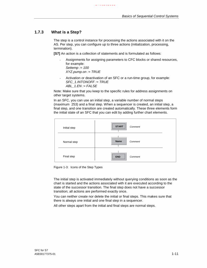
In an SFC, you can use an initial step, a variable number of normal steps(maximum 253) and a final step. When a sequencer is created, an initial step, afinal step, and one transition are created automatically. These three elements formthe initial state of an SFC that you can edit by adding further chart elements.
Name Comment
Comment
Comment
Normal step
Initial step
Final step
START
END
Figure 1-3: Icons of the Step Types
The initial step is activated immediately without querying conditions as soon as thechart is started and the actions associated with it are executed according to thestate of the successor transition. The final step does not have a successortransition; all actions are performed exactly once.
You can neither create nor delete the initial or final steps. This makes sure thatthere is always one initial and one final step in a sequencer.
All other steps apart from the initial and final steps are normal steps.
17.02.200317.02.200317.02.2003

Basics of Sequential Control Systems
SFC for S71-12 A5E00177375-01
1.7.4 What is a Transition?
A transition contains the condition with which a sequential control system passescontrol from one step to the next. Several conditions can be logically combinedusing Boolean operators. The result of the logic operation decides whether controlis passed to the next step.
CommentName
Figure 1-4: Icon of the Transition
[S7] The result of a transition condition is obtained from a Boolean expressionformed by logic operations on shared addresses, CFC block I/Os, run-time groupstates, and the SFC state.
During compilation, an empty transition is given the default value TRUE. Thisdefault is necessary because while the formulation of a condition is optional, adefined value is required on the AS to allow control to be passed on.
If several transitions become valid at the same time (in alternative sequences, in aloop or in jumps) the system automatically assigns priority from left to right indescending order.
1.7.5 What is a Text?
With the “text" chart element, you can insert any static texts (free texts) in a chartas required.
The text object is a box with a character string with one or more lines. During theanalysis phase, this allows you to insert descriptive texts into the SFC that canlater be replaced by automation functions.
These free texts are not embedded in the topological sequencer structure and aretherefore not repositioned if you change the topology but remain where they are.
17.02.200317.02.200317.02.2003

Basics of Sequential Control Systems
SFC for S7A5E00177375-01 1-13
1.7.6 What is a Sequence and What is a Sequencer?
A sequence is a path made up of steps and transitions that can be created with aselectable length and inserted in the sequential control system.
A self-contained sequence within a sequential control system forms a sequencepath, for example between the divergence and convergence of a parallel oralternative sequence. In the SFC a full sequencer can also be called a sequencepath, this runs from the initial step to the final step (see Figure 1-5).
Self-contained sequence (sequencer)Sequence
Figure 1-5: Sequences
17.02.200317.02.200317.02.2003

Basics of Sequential Control Systems
SFC for S71-14 A5E00177375-01
1.7.7 What is a Simultaneous Sequence?
If the control diverges along two or more sequence paths that should be executedat the same time, simultaneous sequences are used.
A simultaneous sequence consists of at least two sequence paths that areexecuted at the same time.
A simultaneous sequence is always preceded by a transition (or an alternativesequence). The simultaneous sequence paths end in a simultaneous convergencethat is always followed by a transition (or alternative sequences).
The successor transition executes only when all actions of the steps at the end ofevery sequence path have been executed (apart from the “termination" action) andthe condition for passing on control is satisfied (synchronization).
Sequence path
Successor transition
Figure 1-6: Example a Simultaneous Sequence with Four Sequence Paths
17.02.200317.02.200317.02.2003

Basics of Sequential Control Systems
SFC for S7A5E00177375-01 1-15
1.7.8 What is an Alternative Sequence?
If control diverges into two or more sequence paths of which one and only oneshould be executed, alternative sequences are used.
An alternative sequence consists of at least two sequence paths, of which only onewill be executed dependent on the state of the first transition in the individualsequence paths. This means that the path selected is the path whose transition issatisfied first. If more than one transition is true simultaneously, the sequence pathfurthest left with a true transition is executed.
Alternative sequences must be preceded and followed by a step (or simultaneoussequence).
Sequence path
Successor step
Figure 1-7: Example of an Alternative Sequence with Four Sequence Paths
17.02.200317.02.200317.02.2003

Basics of Sequential Control Systems
SFC for S71-16 A5E00177375-01
1.7.9 What is a Loop?
If you want a section of the sequencer to be repeated depending on a transition,you use a loop.
A loop consists of a sequence and a return path with a transition that encloses thesequence (see Figure 1-7). The start of the loop must be immediately following astep and the return path must converge again immediately before a step.
Return path
Successor transition
Sequence
Figure 1-8: Example of a Loop
The transition of the return path is queried after the successor transition.
If the successor transition and the return path transition are true at the same time,the step (or simultaneous sequence) following the successor transition is executed.
Note:
Return paths from within or into simultaneous or alternative sequences are notpossible.
17.02.200317.02.200317.02.2003
Basics of Sequential Control Systems
SFC for S7A5E00177375-01 1-17
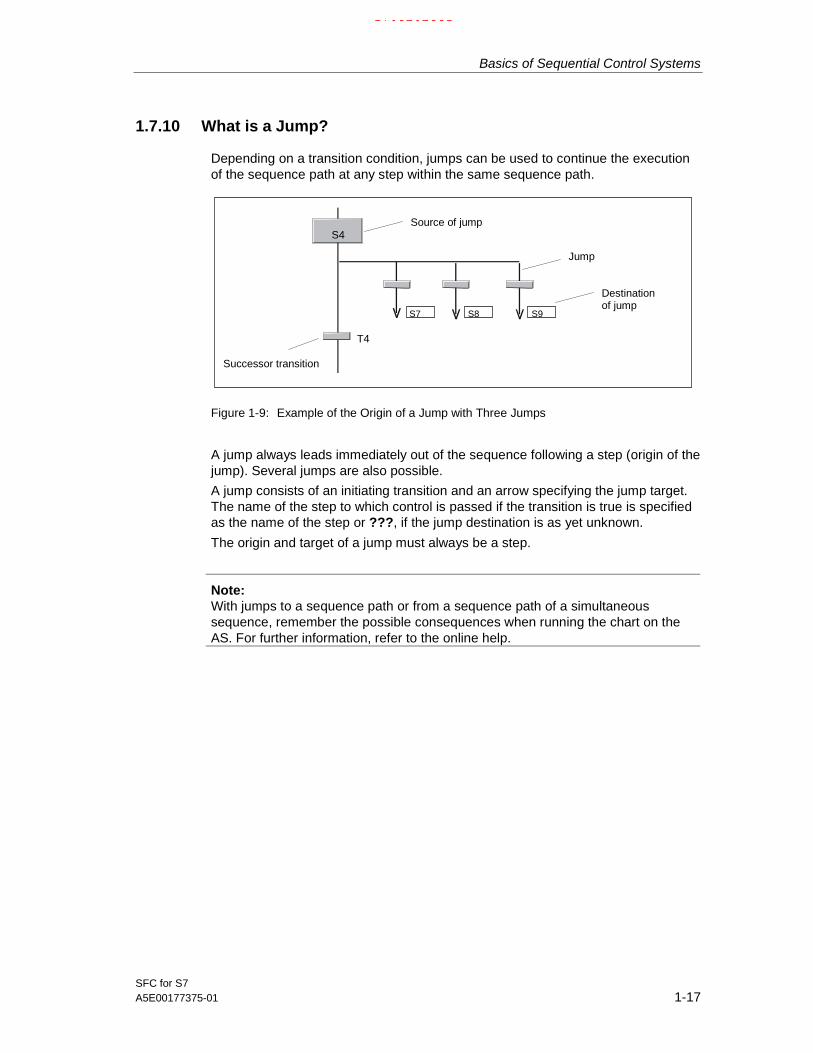
1.7.10 What is a Jump?
Depending on a transition condition, jumps can be used to continue the executionof the sequence path at any step within the same sequence path.
Successor transition
S7 S8 S9
Jump
Destinationof jump
Source of jumpS4
T4
Figure 1-9: Example of the Origin of a Jump with Three Jumps
A jump always leads immediately out of the sequence following a step (origin of thejump). Several jumps are also possible.
A jump consists of an initiating transition and an arrow specifying the jump target.The name of the step to which control is passed if the transition is true is specifiedas the name of the step or ???, if the jump destination is as yet unknown.
The origin and target of a jump must always be a step.
Note:With jumps to a sequence path or from a sequence path of a simultaneoussequence, remember the possible consequences when running the chart on theAS. For further information, refer to the online help.
17.02.200317.02.200317.02.2003

Basics of Sequential Control Systems
SFC for S71-18 A5E00177375-01
17.02.200317.02.200317.02.2003

SFC for S7A5E00177375-01 2-1
2 Working with the SFC Editor
IntroductionWith the SFC editor, you can create sequential control systems graphically andspecify the actions and step control conditions. From beginning (creating the chartor type) to end (compiling and downloading to the AS), the editor provides all thefunctions required.
How to use the editor is described in this chapter.
2.1 Working with Charts, Types, and Instances
2.1.1 How to Create a Chart
• SIMATIC Manager
You create an SFC chart with the SIMATIC Manager by opening the chartfolder of the project in the component view or the hierarchy folder in theplant view and insert the chart there ("Insert > S7 Software > SFC" or "Insert >Technological Objects > SFC"). The chart is given a standard name by thesystem, for example SFC(1) that you can change. The name must be uniqueon the CPU. This is checked by the system.
• SFC Editor
Open the “New" dialog box in SFC using the menu command “SFC > New...".Select the project and the chart folder in the component view.
[S7] In the plant view or the process object view, open the hierarchy folderof the project in which you want to create the chart.
In the "Object type" box, select "SFC" from the drop-down list box and enter achart name in the "Object name" box. The name must be unique in the chartfolder; this is checked by the system. When you click “OK", a new window isopened with the SFC chart (initial status).
17.02.200317.02.200317.02.2003

Working with the SFC Editor
SFC for S72-2 A5E00177375-01
2.1.2 [S7] Creating an SFC Type
You create an SFC type as follows:
• In the component view of the SIMATIC Manager with the chart folder selected,right-click to open the context-sensitive menu ("Insert New Object > SFCType") or select the menu command "Paste > S7 Software > SFC Type".
• In the SFC editor with the menu command "SFC > New...". In the "New" dialogbox, select "SFC Type" in the drop-down list box of the "Object type" box.
The next free FB number is automatically reserved for the SFC type and this iscopied to the block folder as a type template. This allows you to configuremessages and instances of the type once it is created without having to compilethe type. The FB number can be modified later in the Object Properties dialog.
When you first create an SFC type, the blocks required for compiling are copied tothe current program and then managed on the ES. The blocks are included in thesupplied block library.
Note: SFC types cannot be assigned to a hierarchy folder in the plant view, sincethey themselves are not relevant to the running of a project (from the point of viewof the process being automated).
2.1.3 [S7] Creating an SFC Instance
You create an SFC instance by dragging the SFC type from the block catalog tothe CFC chart in CFC.The SFC types in the chart folder are displayed in the CFC block catalog (in "Allblocks" and in the folder of the family if they are assigned to a family, otherwise inthe "Other blocks" folder).
The SFC instance is represented like a CFC instance block. If there is not enoughspace to position the SFC instance; in other words, it overlaps one or more existingobjects, it is displayed as an "overlapping block" (light gray and without visibleI/Os). After moving them to a free position in the chart, the overlapping blocks aredisplayed as "normal" blocks again.
You can assign parameter values to the SFC instance in the CFC chart andinterconnect it.
17.02.200317.02.200317.02.2003

Working with the SFC Editor
SFC for S7A5E00177375-01 2-3
2.1.4 Opening a Chart or Type
• SIMATIC Manager:You can open a chart or type in the SIMATIC Manager by double-clicking onthe required icon in the project in the Charts folder of the S7 program. The SFCeditor is then started and the selected chart or type is opened.
• SFC Editor:In the "Open" dialog of the SFC editor, you select "SFC" or "SFC type" from thedrop-down list box in the "Object type" box and then select the required object.
In the “SFC" menu of the SFC editor, you will see the last SFCs to be editedshown as menu entries. If you select one of these names, the relevant chart ortype is opened or, if it is already open, is displayed in the foreground.
2.1.5 [S7] Opening an SFC Instance
You can open SFC instances in the CFC chart. The SFC is started with thetopology of the SFC instance. This topology is only viewable in the edit mode andcannot be modified. The properties of the SFC instance and the interface can bemodified.
2.1.6 Copying Charts
With the SIMATIC Manager, you can copy charts; in other words, you can transfertested substructures or even entire structures from one CPU to another CPU of thesame type or copy them within the same CPU. Existing references are not lost ifthe relevant charts are copied together at one time.
For more detailed information on copying, refer to the SFC online help.
2.1.7 [S7] Copying and Moving SFC Types
SFC types are copied in the SIMATIC Manager. The run-time objects belonging tothe SFC type are also copied. If the SFC type is not up to date (time stamp of theFB is older than the time stamp of the SFC type), a message will be displayed. Ifthe SFC type already exists at the destination (SFC type with the same name), thisis overwritten following a prompt for confirmation and any properties that differ fromthe previous type are passed on to the SFC instances.
SFC types are moved in the SIMATIC Manager. SFC types can only be movedwhen there are no SFC instances of the SFC type in the source. The run-timeobjects belonging to the SFC type are also moved. If the SFC type already existsat the destination (SFC type with the same name), this is overwritten following aprompt for confirmation and any differences compared with the previous type arepassed on to the SFC instances.
17.02.200317.02.200317.02.2003

Working with the SFC Editor
SFC for S72-4 A5E00177375-01
2.1.8 [S7] Copying and Moving SFC Instances
You can copy or move SFC instances in the CFC chart, between CFC charts orindirectly by copying/moving the CFC chart in the SIMATIC Manager. The run-timeobjects belonging to the SFC instance are also copied/moved.
If you copy an SFC instance within a CFC chart or between CFC charts of thesame chart folder or copy a CFC chart within a chart folder, the SFC instance isalso copied. The run-time objects belonging to the SFC instance are also copied. Ifyou copy an SFC instance between CFC charts from different chart folders or copya CFC chart to a different chart folder, the SFC type is also copied.
If you move an SFC instance within a CFC chart, you merely change the positionof the SFC instance. If you move an SFC instance between CFC charts of thesame chart folder, the SFC instance is also moved. The run-time objects belongingto the SFC instance are retained. If you move an SFC instance between CFCcharts from different chart folders or move a CFC chart to a different chart folder,the SFC type is also copied or moved.
2.1.9 Deleting Charts and Types
You delete SFC charts and SFC types only in the SIMATIC Manager.
• You delete SFC charts in the same way as other objects (hierarchy folders, OSpictures, ...) by selecting the object and pressing the DEL key.
• [S7] You can only delete SFC types, when no SFC instances of the SFC typeexist. If instances of an SFC type exist, a message to this effect is displayed.
The run-time objects belonging to the SFC type are also deleted.
You cannot delete charts or types in the SFC editor.
2.1.10 [S7] Deleting SFC Instances
You delete SFC instances in the CFC chart or indirectly by deleting the CFC chartin the SIMATIC Manager. The run-time objects belonging to the SFC instance arealso deleted.
17.02.200317.02.200317.02.2003

Working with the SFC Editor
SFC for S7A5E00177375-01 2-5
2.1.11 Representation and Interconnection of the External View
The interface of the SFC chart is displayed as a graphic "external view" in a CFCchart.
With the menu command "View > External View", you open CFC with a windowdisplaying the external view of the SFC chart.
Display
The external view displays the SFC like a block; in other words with the standardinterface derived from the SFC run-time system. To distinguish it from CFC blocksand hierarchical charts, the external view has the "SFC chart" icon in theheader. The block name is the same as the SFC chart name and cannot bemodified.
Interconnection
You can assign textual interconnections to the I/Os and/or interconnect them withcompatible I/Os of other objects or with shared addresses. All interconnections arevia the sheet bar which means that you cannot place any objects (for example,blocks) in this window.
You cannot make modifications to the interface here, in other words, you cannotopen the editor.
Properties
You can display the object properties for the entire interface (double-click in theheader of the external view) or for the individual I/Os (double-click on aninterconnection).
17.02.200317.02.200317.02.2003
Working with the SFC Editor
SFC for S72-6 A5E00177375-01
2.2 Properties of Charts and Types
2.2.1 Adapting Chart Properties
You can modify the chart properties for the active chart. With the menu command“SFC > Properties", you open the properties dialog box.
You can modify the chart properties in the following three tabs.
• GeneralThis tab is used to enter or modify the chart name, the author and thecomment.
• Operating Parameters ASHere, you can make the settings for the initial status of the chart. Theseinclude: "step control mode", "mode", "command output", "cyclic operation" and"time monitoring" as well as the options for starting the chart: "Autostart" and"Use default operating parameters when SFC chart starts".
• OSIf the “Transfer chart to OS for visualization" option is set, the SFC chart istransferred to the OS automatically with the next OS compilation.
For a description of the operating parameters, refer to Section 3.2, How the SFCRunss and in the SFC online help.
2.2.2 [S7] Adapting Type Properties
You can display and modify the properties for the active SFC type. The "SFC >Properties..." menu command opens a dialog box. You can modify the properties inthe following three tabs.
• GeneralThis tab includes the entry and modification of the type name, the author, theversion, the family, the FB number, and the comment.
• Operating Parameters ASIn this tab, you can set the defaults for the initial status of the SFC instancescreated from this type. These include: "step control mode", "mode", "commandoutput", "cyclic operation", and "time monitoring" as well as the options forstarting the SFC instance: "Autostart" and "Use default operating parameterswhen SFC chart starts".
17.02.200317.02.200317.02.2003

Working with the SFC Editor
SFC for S7A5E00177375-01 2-7
• OptionsIn this tab, you can classify the SFC type for SIMATIC BATCH:
- The category"None" � there is no classification"EOP" � the SFC type is classified as an "operation type""EPH" � the SFC type is classified as a "phase type".
- Allow operator instructions on the OS; in other words, allow input of valuesin the operator dialog.
2.2.3 [S7] Adapting Instance Properties
You can display and modify the properties for the SFC instance opened in theCFC. The "SFC > Properties..." menu command opens a dialog box with the threefollowing tabs:
• GeneralThis tab is used to enter or modify the instance name and the comment. Allother properties (see SFC type) can only be read and not modified.
• Operating Parameters ASIn this tab, you can change the SFC instance operating parameters (see SFCType).
• OptionsIn this tab, you can display the options set for the SFC type for SIMATICBATCH:
17.02.200317.02.200317.02.2003

Working with the SFC Editor
SFC for S72-8 A5E00177375-01
2.3 The Run-Time Properties
The run-time properties of an SFC chart or SFC instance determine how the SFCis included in the execution of the entire structure on the AS. These properties arevital to the performance of the AS in terms of reaction times, dead times, or thestability of time-dependent structures, for example control loops.
An SFC instance is treated like a CFC block and therefore only the SFC chart isdealt with below.
You edit the Run Sequence with the run sequence editor. This is started with the
menu command "Edit > Run Sequence..." or with the button in the toolbar .
2.3.1 Run Sequence
Each SFC chart is installed in a run sequence.
Each SFC chart must be installed in at least two tasks; in the
• task for the startup behavior ( [S7] OB100)
• task for normal execution ( [S7] e.g. OB35).
Changing the Run SequenceTo change the run sequence, select the SFC chart icon, select “Cut", then selectthe required task and then “Paste". If you have selected a task, the SFC chart isinstalled at the beginning of the task. If you have selected an object within the task,the SFC chart is installed after it.
As an alternative to cut / paste, you can also drag a chart from an open task toanother task with the mouse.
Removing an SFC Chart from a TaskTo remove a chart from a task, select the chart and delete it with the "Delete"function or with the DEL key. Before the chart is deleted, you are prompted toconfirm your intention.
Installing an SFC Chart in a Run-Time GroupYou create a run-time group with the menu command “Insert Run-Time Group..."for the selected task (in the “Edit" menu or in the context-sensitive menu). In thedialog box, you enter the name and any comment you require and the run-timeattributes for the scan rate and phase offset.
Install the SFC chart in the run-time group as usual (same procedure as installationin a task).
17.02.200317.02.200317.02.2003

Working with the SFC Editor
SFC for S7A5E00177375-01 2-9
2.3.2 Run-Time Groups
SFC charts can be installed in run-time groups if you want them to have theattributes scan rate and/or phase offset. The attributes can be set only with theobject properties of the run-time group; in other words, all charts of the run-timegroup have the same “scan rate" and “phase offset".
By using SFC charts in run-time groups, technologically-oriented groups can beformed in conjunction with CFC charts. From a technological point of view, a betterstructuring of the project can be achieved that promises a considerableimprovement in performance when configurations are changed (among otherthings due to shorter compilation times).
2.3.2.1 Run-Time Attributes of the Run-Time Group
A run-time group has the following three attributes:
• Enable
• Scan rate
• Phase offset
[S7] The Enable AttributeThe run-time group is activated and deactivated with the enable attribute (on=1,off=0). As long as 0 is set, the run-time group will not be run regardless of anyother conditions.
The enable attribute can be set dynamically. In this case, for example, the value ofa block output or the statement of a step decides whether or not the run-time groupis activated or deactivated.
[S7] The Attributes “Scan Rate" and “Phase Offset"These attributes cannot be assigned directly to an SFC chart. Charts can only begiven these attributes by installing them in a run-time group from which they inheritthe selected attributes.An SFC chart that is not installed in a run-time group has the default: “scan rate =1" and “phase offset = 0".
If you want different SFC charts on a CPU to run with different run-time attributes,they must be installed in different run-time groups.
Note: Since the SFC chart does not have its own (modifiable) run-time properties,the object properties of the selected SFC chart cannot be opened in the runsequence.
17.02.200317.02.200317.02.2003

Working with the SFC Editor
SFC for S72-10 A5E00177375-01
[S7] Changing the Scan Rate and Phase OffsetIf you want to modify the run-time attributes, select the SFC chart in the RunSequence window and select the “Object Properties" menu command (context-sensitive menu or “Edit" menu).
• Scan rate:The scan rate specifies whether the SFC chart is executed by the task eachtime the task is run or only in every nth run. Where “n" is an integer (n=2t,where 0 <= t <= 15). The steps are a multiple of the basic cycle rate of thetask.Default: 1 (execute every run)
Example:Basic cycle of a cyclic interrupt (OB33): 500 msPossible cycle rates with scan rate: 1s, 2s, 4s, 8s, 16s etc.
• Phase offset:The phase offset can be used to achieve a better distribution of load on theCPU. It must be considered in conjunction with “n", the scan rate. The SFCchart is processed as often as specified by “n", offset in each case by “m" unitsof the cycle.Where “m" is an integer and 0 ≤ m ≤ (n-1)Default: 0 (no phase offset)
Example:Basic cycle of a cyclic interrupt (OB33): 500 msScan rate: 16. The SFC chart is executed every 8 seconds (0.5s x 16).Phase offset: 3. The SFC chart is executed after 1.5s; 9.5s; 17.5s etc.
! Caution!Whenever possible, you should only use the scan rate and phase offset in thetasks that execute in defined cycles; in other words, with cyclic interrupts. In allother tasks you should be extremely careful, particularly with hardware interruptsand special tasks. Here, you should not change the default scan rate=1 andphase offset=0.
17.02.200317.02.200317.02.2003

Working with the SFC Editor
SFC for S7A5E00177375-01 2-11
2.4 Configuring Sequential Control Systems
RequirementsBefore you can configure sequential control systems, you must first create therequired basic control functions with CFC and/or STEP 7 tools. At the same time,the AS blocks to be used in the SFC charts or SFC instances are also inserted.Automation functions that do not yet exist can be added later and then used in anSFC.
Procedure
When you configure a sequential control system (SFC chart or SFC type),
• create the sequence topology with the required number of sequencers and therequired arrangement of SFC elements.
• configure the start condition, the preprocessing, and the postprocessing in theProperties dialog of the sequencers.
• configure the steps and transitions, the actions and conditions in the Propertiesdialog of the steps and transitions. These procedures are dealt with in greaterdetail in the following topics.
Color SettingsThe objects of a chart are displayed in different colors depending on their currentstate. The elements of an unselected sequential control system, for example, aredisplayed in “white" (parameters not set) or “gray" (parameters set) and in “blue"when they are selected.
With the “Options > Customize > Colors..." menu command, you can select yourown color scheme for certain elements.
17.02.200317.02.200317.02.2003

Working with the SFC Editor
SFC for S72-12 A5E00177375-01
2.4.1 Creating the Sequencer Topology
Appearance of the Sequencer
in its initial state, the new SFC consists of one sequencer; this can, however, beextended to up to 8 (SFC chart) or 32 (SFC type) sequencers. Each sequencer iscreated in a separate working window; You can change from one sequencer to thenext with the tabs at the lower edge of the window.
A newly created sequencer ("Insert > Sequence > ..." menu command) is insertedin its initial status consisting of an initial step, transition and final step, at a selectedposition in the SFC and a tab is added at the lower edge of the window. Each tabcontains the name of the sequencer (RUN, SEQ1, ...).
See also Section 2.4.2, Configuring Several Sequencers
If you insert or delete SFC elements in the sequencer, its layout is changedautomatically according to predefined rules. These determine the spacing betweenelements, the size of steps and transitions, the alignment of alternative sequencesetc. You can change the display/layout rules at any time (Options > Customize >Display... menu command).
You can center the sequencer topology in the window. With the zoom functions,you can increase or reduce the size of the display (in percentage steps determinedby the zoom factor).
Adding ElementsTo add further elements to the SFC, select the icon of the required element in theelement bar.
The mouse pointer changes its appearance from an arrow to the selected symbolwith a positioning cross. To insert the sequence element, position the cross at therequired position (the insert position is indicated by a green line) and then click theleft mouse button. The inserted elements are selected and displayed in color.
Syntax Rules
The sequencer topology is formed by the sequences of steps and transitions. Thefundamental rule of the sequencer topology is that a step (S) must be followed by atransition (T) and a transition must always be followed by a step (sequence : S-T-Sor T-S-T). The editor automatically adheres to the rules.
Example:
If you insert a simultaneous sequence in a sequencer following a transition andbefore a step, a transition is created automatically before the step since the syntaxrules require a transition before and after a simultaneous sequence.
17.02.200317.02.200317.02.2003
Working with the SFC Editor
SFC for S7A5E00177375-01 2-13
2.4.2 Configuring Several Sequencers
An SFC can contain several sequencers that can be used for different applications.By specifying different start conditions, you can arrange for a particular sequencerto start when a particular event occurs. You can, for example, configure a separatesequencer for every operating state (ready, active, error, ...) or for every controlstrategy (heating, cooling, tempering, ...).
Note:
There are ready-made sequencer templates available in the "SFC Library". Youcan copy these templates and adapt them to your own purposes.
[S7] Start Condition of the Sequencers
The first sequencer of a chart or type has the condition "SFC.RUN=1"; the startcondition of every further sequencer you add is empty and therefore not satisfiedand it will never execute. In contrast to newly created transitions that are alwayssatisfied, a new sequencer must always be given a defined start condition(Sequencer Properties > Start Condition tab).
Since it is possible that several start conditions can be satisfied at the same time,you can assign different priorities to the individual sequencers (SequencerProperties > General tab, Priority: 1 to 32).
You can formulate the start condition of a sequencer so that the status of theoperating state logic is checked and the appropriate sequencer executes when theSFC is in a particular state.
Examples
Example 1: You configure a sequencer with a start condition that queries one ofthe control strategies of the SFC. The formulation is, for example, "SFC.QCS=1". Ifthe SFC is set to this control strategy, the sequencer executes and is notdependent on the operating state of the SFC.
Example 2: You configure a sequencer with the start condition "SFC.IDLE=1". Thissequencer executes when the operating state is "Ready".
Example 3: Any process status can also be queried as the start condition. Youinterconnect it with the external signal "LOCKERROR" (input of the SFC) �, theSFC changes to the "Error" state if the error signal is applied. You also configure asequencer for handling the problem whose start condition is, for example,"SFC.ERROR=1 AND process status=1".
Example 4: As an alternative to example 3, problem handling can also executewithout a state change. To achieve this, you configure a sequencer with the startcondition "process status=1" and assign it high priority. This sequencer alwaysexecutes when the problem occurs and the sequencer currently executing has alower priority than the sequencer for handling the problem. In this case, you do notinterconnect the process status with the "LOCKERROR" input otherwise this wouldmean a change to the "Error" state.
17.02.200317.02.200317.02.2003

Working with the SFC Editor
SFC for S72-14 A5E00177375-01
Notes on Configuration
• You can insert a new sequencer consisting of an initial step, a transition and afinal step with the menu commands "Insert > Sequence > Before CurrentSequence" or "Insert > Sequence > At End".
• Ready-made sequencers are already available for various standard scenarios.These sequencer templates are available in the "SFC Library". You can copythese templates and adapt them to your own purposes.
• You can copy sequencers and paste them again or move them to change theirorder.
• The names of the steps and transitions must be unique within a sequencer, thesame names can be used in different sequencers.
• You can also configure a cyclic action for each sequencer. The cyclic actionconsists of a part that is executed before the cyclic sequencer processing, thepreprocessing and a part that is executed after the cyclic sequencerprocessing, the postprocessing. You configure both parts in the "SequencerProperties" dialog box. The dialog box contains the "Preprocessing" and"Postprocessing" tabs whose structure corresponds to the processing phasesof steps.
17.02.200317.02.200317.02.2003
Working with the SFC Editor
SFC for S7A5E00177375-01 2-15
2.5 Creating SFC Elements
2.5.1 Creating a Sequence
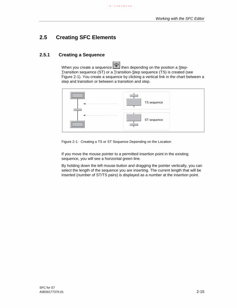
When you create a sequence then depending on the position a Step-Transition sequence (ST) or a Transition-Step sequence (TS) is created (seeFigure 2-1). You create a sequence by clicking a vertical link in the chart between astep and transition or between a transition and step.
ST sequence
TS sequence
Figure 2-1: Creating a TS or ST Sequence Depending on the Location
If you move the mouse pointer to a permitted insertion point in the existingsequence, you will see a horizontal green line.
By holding down the left mouse button and dragging the pointer vertically, you canselect the length of the sequence you are inserting. The current length that will beinserted (number of ST/TS pairs) is displayed as a number at the insertion point.
17.02.200317.02.200317.02.2003

Working with the SFC Editor
SFC for S72-16 A5E00177375-01
2.5.2 Creating and Extending a Simultaneous Sequence
When you create a simultaneous sequence two sequence paths aregenerated each consisting of one step. Depending on the point of insertion, afurther transition is added automatically before or after the simultaneous sequenceto ensure that the syntax is maintained.
If you open a lasso (in the Edit mode) around the elements of a sequence path, theenclosed elements become part of the left sequence path of the generatedsimultaneous sequence.
S5
S6
S9S5
S6Lasso
T4 T4
T5
T6
T5
T6
You can add further sequence paths to a simultaneous sequence or delete pathsand also insert them in a different sequence. You can move a sequence pathwithin a simultaneous sequence or to any other position in the chart (except in thereturn branch of a loop). If you delete the second last path, the remaining path issimply integrated in the surrounding structure and the simultaneous sequence iseliminated.
To add further sequence paths, simultaneous sequences, or alternative sequencesto a simultaneous sequence, change to the required insert mode and click themouse with the positioning cross located on the upper or lower double line.
If you move the mouse pointer to a permitted insertion point in the existingsequencer, you will see a horizontal green line. Within the simultaneous sequence(in the vicinity of the upper simultaneous divergence or lower simultaneousconvergence), the vertical green line indicates that you are inserting a furthersequence path. If, for example, you insert an alternative sequence beside asequence path, an extra step is created before and after the sequence to maintainthe correct syntax.
17.02.200317.02.200317.02.2003
Working with the SFC Editor
SFC for S7A5E00177375-01 2-17
2.5.3 Creating and Extending an Alternative Sequence
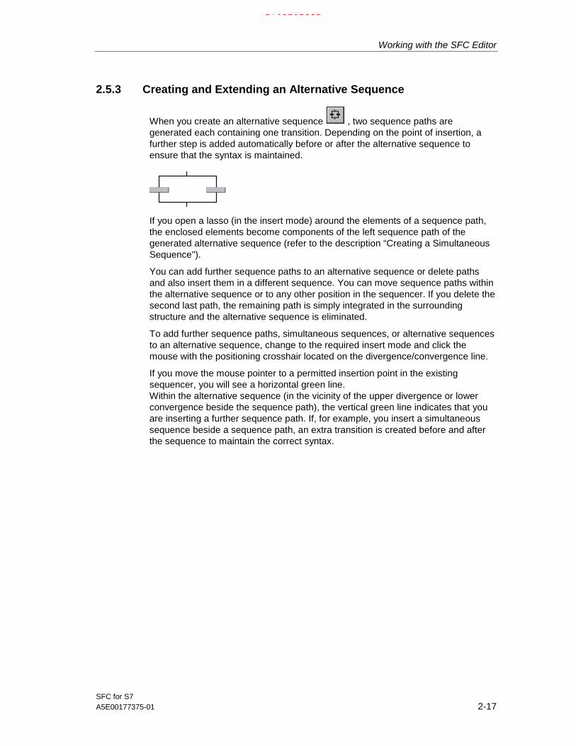
When you create an alternative sequence , two sequence paths aregenerated each containing one transition. Depending on the point of insertion, afurther step is added automatically before or after the alternative sequence toensure that the syntax is maintained.
If you open a lasso (in the insert mode) around the elements of a sequence path,the enclosed elements become components of the left sequence path of thegenerated alternative sequence (refer to the description “Creating a SimultaneousSequence").
You can add further sequence paths to an alternative sequence or delete pathsand also insert them in a different sequence. You can move sequence paths withinthe alternative sequence or to any other position in the sequencer. If you delete thesecond last path, the remaining path is simply integrated in the surroundingstructure and the alternative sequence is eliminated.
To add further sequence paths, simultaneous sequences, or alternative sequencesto an alternative sequence, change to the required insert mode and click themouse with the positioning crosshair located on the divergence/convergence line.
If you move the mouse pointer to a permitted insertion point in the existingsequencer, you will see a horizontal green line.Within the alternative sequence (in the vicinity of the upper divergence or lowerconvergence beside the sequence path), the vertical green line indicates that youare inserting a further sequence path. If, for example, you insert a simultaneoussequence beside a sequence path, an extra transition is created before and afterthe sequence to maintain the correct syntax.
17.02.200317.02.200317.02.2003

Working with the SFC Editor
SFC for S72-18 A5E00177375-01
2.5.4 Creating a Loop
When you create a loop a sequence path (that can consist of a single step)and a return path with a transition are generated.
You can create loops around existing sequences. You select the beginning andend of the loop by positioning the mouse pointer on the vertical link, holding downthe left mouse button and dragging vertically to the required position and releasingthe button. The syntax is maintained by adding whatever elements are necessary.If, for example, you create a loop around a transition, the enclosed sequence thenconsists of this transition and a step before and after it. Below the loop, a furthertransition is added.
The start and end point of a loop cannot be modified later. You can, however,move the elements you want to be included in the sequence of the loop into theloop and achieve the same result.
17.02.200317.02.200317.02.2003

Working with the SFC Editor
SFC for S7A5E00177375-01 2-19
2.5.5 Creating a Jump
When you insert a jump , a transition is created with an arrow and informationabout the destination of the jump.
???
When inserting loop, click on the vertical connecting line of the sequenceimmediately following a step. With a single click, you create a jump with anundefined destination. The destination is displayed as question marks (???).
If you require more than one jump from a step, click on the horizontal line of thejump branch. The branch with the jumps is then extended by a jump with eachclick.
When you insert the jump, you can also select the jump destination directly. Dragthe mouse from the point of origin of the jump directly to the destination step andthen release the mouse button. Instead of the question mark, the name of the stepis now entered as the jump destination.
Note:With jumps to a sequence path or from a sequence path of a simultaneoussequence, remember the possible consequences when running the chart on theAS.For further information, refer to the online help.
Changing the Destination of a JumpYou specify the destination of the jump by changing the name (???) in the objectproperties of the destination. Double-click the destination to open a dialog box. Allthe existing steps of the chart are listed and can be sorted. From this list, youselect the step name for the destination of the jump.
Note:If the jump destination is deleted, all the jumps to this step become undefined.If the step name of a jump destination is changed later, all the jumps to the stepare automatically adapted.
17.02.200317.02.200317.02.2003

Working with the SFC Editor
SFC for S72-20 A5E00177375-01
2.5.6 Creating and Editing Text Objects
You can insert, delete, copy, and move a text object at any (free) position in thechart (you cannot drag to other charts).
After inserting a text object using the button in the toolbar or selecting the"Insert > Text" menu command, an open text box is displayed in the window. Thetext cursor is active and you can begin editing immediately. A line break is addedautomatically at the right edge of the box. If you enter more text than can bedisplayed in the box, the size of the box is not increased automatically and the textis moved out of the visible area. You can make the entire text visible by increasingthe size of the box manually.
To change the size of a box, click on the box handles and drag with the mouseuntil the required size is reached. If you change the width of the box, the length ofthe text lines is automatically adapted. You can pick up the box using the handlesof the frame and move it to any position in the window.
When you open a text box, the cursor is positioned at the point in the text at whichyou clicked with the mouse. You can exit the editing mode and close the text boxby clicking outside the text box with the mouse.
Note: If elements of the sequence topology are covered by the text object, the textobject is displayed as a frame with a transparent surface (no content). The chartelements below it remain visible.
Copying, Moving, DeletingWith the mouse pointer over the selected text box (displayed in a frame), open thecontext-sensitive menu with the right mouse button. This contains the menucommands: "Cut Text Object", "Copy Text Object", Delete Text Object".
To paste, click on a free position in the chart and then select the “Paste" menucommand (context-sensitive menu or “Edit" menu). Click again at the requiredposition to insert the text object (the mouse pointer is displayed as a symbol for“inserting" or “copying").
17.02.200317.02.200317.02.2003

Working with the SFC Editor
SFC for S7A5E00177375-01 2-21
2.6 Editing SFC Elements
In the “Edit" menu (and in the context-sensitive menu), you will find furtherfunctions for editing the SFC.
Copy:You can copy the selected elements of a sequence path that form a syntactical unit(sequence of elements without gaps) and position them at a different, syntacticallycorrect position within the sequence path or in a different sequence path on thesame or another CPU. If necessary, new names may be assigned to the copiedelements automatically. The copied elements contain the same actions orconditions as the originals.Copying jumps: If you copy a sequence that contains a jump and the step of thejump destination, the jump destination is adapted appropriately in the copy.If you copy a sequence that contains a jump but the destination of the jump is notwithin the copied object, the jump destination is undefined (???).
Cut and Paste: You can move the selected elements of a sequence that form asyntactical unit (no gaps) to another syntactically correct position within thesequencer or to another sequencer of the same or a different CPU (cut and paste).
Delete: The selected elements are removed from the sequencer topology followinga prompt for confirmation ("Do you really want to delete the selected objects?"). Ifyou delete only one element from a syntactical unit, the syntax is immediatelyrestored by entering a new element to suit the syntax (this has no parametersassigned). This means that you have only deleted the parameter settings for theobject.
The last step of a sequence in a simultaneous sequence cannot be deleted. Todelete a sequence consisting of only one last step, you must select the sequencepath by clicking on the vertical link.The same principle applies to alternative sequences.
If you only select the transition in a jump, its content is deleted; if you select thejump destination (transition and jump destination are selected), the jump is deleted.
17.02.200317.02.200317.02.2003

Working with the SFC Editor
SFC for S72-22 A5E00177375-01
2.7 Editing in the Object Properties Dialog
The steps and transitions entered in the sequence topology must now be linked tothe “block world" or basic control. You do this in the "Properties" a dialog for thesteps and transitions (Sections 2.7.1 and 2.7.2).
2.7.1 Editing Object Properties: Step
You open the object properties by double-clicking the step you want to edit or usingthe menu command “Object Properties..." of the “Edit" menu or the context-sensitive menu if a step is already selected. A dialog box is displayed in which youspecify the properties or formulate the actions.
When you edit the step, the Properties dialog is divided into four tabs:
“General" Tab
In the "General" tab, you can enter or modify the step name, minimum andmaximum execution time, the comment for the step and the OS comment. In the"Number" box, you can see the unique number of the step in the sequencer asassigned by SFC.
By clicking the “Confirmation" check box, you can assign a flag to the step. Thisflag determines the behavior of the step when the chart is run on the AS in the “T /T and C" mode in other words, transitions following a step with this flag onlybecome active and pass control to successor steps when they are satisfied andconfirmed by the operator (as in the “T and C" mode). Without these flags, thesuccessor transitions become active once their conditions are satisfied (as in the“T" mode).
In the Minimum: box, you can set the minimum time that a step should remainactive regardless of whether the successor transition is already satisfied.
With the Maximum: setting, you can specify a time for the time monitoring limitingthe maximum time that the step can be active.
Comment and OS comment boxes, you can enter comment text, for example,describing the actions to be executed by the step (maximum characters for step:80, for OS: 512). The OS comment is used in process control for visualizing thestep.
17.02.200317.02.200317.02.2003

Working with the SFC Editor
SFC for S7A5E00177375-01 2-23
Initialization/Processing/Termination TabsThe tabs for the actions (processing phases) Initialization, Processing andTermination are structured identically. Here, you configure the statements that willcontrol the process during the initial, normal, and final processing of the step (seeSection 3.3.7, Phases of a Step).The statements are adopted as OS comments if the check box is selected in therelevant line.
Formulating ActionsYou enter the statements for actions in a formatted dialog. For each step, you canformulate up to 50 statements per action. Ten of these are visible in the dialog box.You can scroll the list with the scroll bar.
If you position the mouse pointer on an input box, the complete entry is displayedas fast information including the data type and object type. Example:
3. DP666\Reactor1\Motor3\\CFC8.Ctrllr2.P_SEL [BOOL] CFC
A double backslash ( \\ ) is displayed between the path and the CFC name.
In unselected lines, you can use the “Copy/Paste Action" functions in the context-sensitive menu to copy the statements of a complete action and paste them intoanother action. Using this function, you can, for example, copy the statements fromthe “Initialization" action to the “Termination" action and then change the settings“TRUE" to “FALSE".
You will find the formulation options in the online help for SFC.
Entering AddressesUsing the “Browse" dialog: When you browse (for example through CFC charts), all the available objects ofthe chart folder are found and displayed. Using a filter, you can list the I/Os that areof interest in this particular phase of configuration. The filter is active only when thecriteria are clearly defined; in other words, if an address is, for example, a constant,all I/Os are displayed unfiltered and can be selected for the second address.You can insert the selected I/O in the address field with “Apply", by double-clickingor by dragging.
From the I/O window:You can also drag the I/Os of the SFC directly from the window of the I/Os to theaddress box of the Properties dialog.
From the CFC chart:With the CFC chart open, you can select the block I/Os and can drag them to theaddress box of the Properties dialog.
If you insert a block I/O with a value identifier in the address box, the valueidentifier is also entered in the right (empty) address box. If there is more than onevalue identifier for this I/O, you can open the drop-down list box with the valueidentifiers in the right address field by pressing the key combination ALT + DOWN.In the drop-down list box, you can select the required value identifier for thisaddress.
17.02.200317.02.200317.02.2003

Working with the SFC Editor
SFC for S72-24 A5E00177375-01
To allow the value identifiers to be displayed in SFC, the option “Parameter: Valueidentifier" must be selected in “Options > Customize > Layout...".
By editing:With text entries, make sure that the names are consistent. A symbol that does notexist in the symbol list (or a referenced symbol that is subsequently renamed)cannot be checked in the editor and is set up as a textual interconnection.
In the addresses, you can enter CFC block I/Os whose block does not yet reallyexist in the CFC chart. These instructions are displayed in the statement list on ayellow background and are set up as textual interconnections.
Example: Turning the SFC chart on and off[S7] The statement "<SFCchart>.INTONOFF := TRUE", activates an SFC chart.The statement “<SFCchart>.INTONOFF:= FALSE" deactivates an SFC chart (itsfinal step is executed and then the chart is deactivated).
Note:When you enter statements, they are checked so that correct syntactic andsemantic formulation is guaranteed. The program, for example, also checkswhether the data types of the logically combined addresses are compatible.
With SFC access to CFC blocks, please remember the following:
• Being able to modify a type centrally means that it is possible to replace ormodify blocks of which CFC block instances have already been generated. Thetype changes are also made to the CFC blocks. If there are SFC accesses tomodified blocks, these modifications must also be made to the addresses inactions and transitions.
• Access to CFC blocks can also be modified in the relevant CFC chart. Thismodification is, however, restricted to "rewiring" SFC accesses; in other wordsmoving the access to another block I/O (with ALT + Drag&Drop).
Documenting the ConfigurationYou can document the configured actions of the step.With the "Print" button in the Object Properties dialog, you obtain a log of the stepwith information about the properties and assignments for initialization, processingand termination.
17.02.200317.02.200317.02.2003

Working with the SFC Editor
SFC for S7A5E00177375-01 2-25
2.7.2 Edit Object Properties: Transition
You open the object properties by double-clicking the transition you want to edit orusing the menu command “Object Properties..." of the “Edit" menu or the context-sensitive menu if a transition is already selected. A dialog box with three tabs isopened in which you can specify the properties, the conditions and the OScomments.
“General" TabIn the "General" tab, you can enter or change the name and comment.
“Condition" Tab
In the “Condition", you specify the step control conditions for the selectedtransition.
&
&
&
&
&
&
&
11
12
13
6
7
8
9
10
1
2
3
4
5
14
15
16
Figure 2-2: Logical Combination of Conditions with Three-Stage Transition Logic
17.02.200317.02.200317.02.2003

Working with the SFC Editor
SFC for S72-26 A5E00177375-01
Formulating the Conditions of a TransitionYou formulate a transition as a Boolean expression, that can consist of 2 x 5 and 2 x 3 conditions. The conditions are combined using three-stage transition logic.
The Boolean operators are designed as buttons. With a simple mouse click on theoperator, you can change it from "AND (&)" to "OR (≥1)". To make a “NAND" froman “AND" and a “NOR" from an “OR", click the output of the operator. The negationis displayed by a period in bold print on the output line.
You will find the formulation options in the online help for SFC.
If you position the mouse pointer on an input box, the complete entry is displayedas fast information including the data type and object type.
You should whenever possible enter the addresses using the “Browse" selectiondialog or from the open CFC chart since this means that the addresses are unique.
As when selecting addresses for the steps, you can also enter the value identifiersof the I/Os for the transitions.
Note:When you enter conditions, they are checked for consistency so that correctsyntactic and semantic formulation of the subexpression is guaranteed. Theprogram also checks whether the data types of the logically combined addressesare compatible.
The predefined three-stage logic is normally adequate. If you require morecomplex formulations, you can create them as a CFC chart and enter the resultscalculated in the chart as the address for transition conditions.
17.02.200317.02.200317.02.2003
Working with the SFC Editor
SFC for S7A5E00177375-01 2-27
“OS Comment" TabHere, you can enter a comment text for each condition that is displayed on the OSduring process control.
When you first open the “OS Comment" dialog, the formulated condition is enteredas an OS comment and can then be changed as required.
• Unless you edit and modify the OS comment, the OS comment is adaptedautomatically whenever the compare condition is changed. This automaticupdating also applies to renaming, copying, moving or deleting the referencedCFC blocks.
• If you change the condition belonging to a comment text that you have edited,this is not automatically adapted. In this case, a dialog box is opened tellingyou that you should check the comment text. You can cancel the change in thisdialog box by clicking the “Cancel" button.
• You can initialize an individual OS comment in the SFC editor by deleting theOS comment. The text from the compare condition is then used again as theOS comment and from this time onwards is automatically adapted wheneverthe condition is changed providing you do not edit the OS comment.As an alternative: You can enter the original OS comment (text of thecondition) again using the “Use Default" context-sensitive menu command.
• You can edit the OS comments later.With the "Options > Edit OS Comments..." menu command, a dialog is openedin which you can select how the OS comments are handled in the transitions:
- leave unchanged or
- use all conditions.
In this dialog, you can also decide on the range to which the processing of theOS comments applies:
- entire chart folder
- the current chart
- the selected steps/transitions.
Documenting the Configuration
You can document the configured conditions of the transition. With the "Print"button in the Object Properties dialog, you obtain a log of the transition withinformation about the properties and parameters of the conditions.
17.02.200317.02.200317.02.2003

Working with the SFC Editor
SFC for S72-28 A5E00177375-01
2.8 [S7] Creating an SFC Type
There are two possible ways of creating and modifying an SFC type:
• Creating and modifying in a library has the advantage that the master forthe SFC type is always in the library and that the test project can still run until anew version of the SFC type is adopted.
• Creating and modifying in a project has the advantage that every change tothe SFC type can be checked immediately since you are working directly withthe master.
Creating the SFC Type in the Project
You can only create an SFC type when a PCS 7 project already exists.
Basic Procedure:
• Preparations:
- With LAD/FBD/STL: Definition of which I/Os of the blocks (of the blocklibrary you are using) need to be connected to the SFC types (using thesystem attribute "S7_contact" for the block contacts). (This has alreadybeen done for the technological blocks from the PCS 7 library.)
- In CFC: Import the blocks ("Options > Block Types...")
• Creating (SIMATIC Manager):
- Create a new SFC type ("Insert New Object > SFC Type")
- Adapt the SFC type name
- Open the SFC type
• Adaptation (SFC Editor):
- Adapt the properties ("SFC > Properties...");"General" tab: Author, Version, Family, FB number, Comment;"Operating Parameters AS": Options for "Defaults" and "Start Options".
• Characteristics (SFC Editor), see Section 2.9
- Definition of the characteristics ("View > Characteristics")
- Add the control strategies
- Add the setpoints
- Add the process values, block contacts etc.
17.02.200317.02.200317.02.2003
Working with the SFC Editor
SFC for S7A5E00177375-01 2-29
• Sequencers (SFC Editor)
- Adding/editing the sequencers
- Editing the start condition (sequencer properties)
- Possibly editing preprocessing/postprocessing of the sequencer
- Configuring Sequencers
Note:
There are ready-made sequencer templates available in the "SFC Library". Youcan copy these templates and adapt them to your own purposes.
17.02.200317.02.200317.02.2003

Working with the SFC Editor
SFC for S72-30 A5E00177375-01
2.9 [S7] Configuring in the Characteristics Dialog
What are characteristics?
A characteristic is the technology-oriented functionality of an SFC type asdescribed by a set of attributes.
A characteristic is described as follows:
• by the attributes such as data type, initial value, upper limit, ...
• by the I/O names and the I/O group, this is the interface description of the I/Osrequired for the characteristic.
• by mapping the attributes to the I/Os of the I/O group or to the faceplate.
The following characteristics are available for creating the type:
• Control strategiesControl strategies are used for the structuring of an SFC type as required forprocess control. With the Characteristics dialog, you can define controlstrategies so that these can be used in the sequencers (for example heating,cooling, ...). The control strategy can be set by the operator or by a higher-levelcontroller such as SIMATIC BATCH. The control strategies are optional.
• SetpointsSetpoints are used to control the SFC type. These can be set by the operatoror by a higher-level controller such as SIMATIC BATCH. When using controlstrategies, all setpoints are initially assigned to all control strategies. Using theObject Properties dialog of a setpoint, the setpoint can be assigned selectivelyto specific control strategies.
• Process valuesProcess values are used to control the SFC type based on process signals (forexample, the value for the fill level).
• Control valuesControl values are used to control external logic with this SFC type.
• ParametersParameters are used to modify the behavior of the instances of the SFC type.
• Bit memoryBit memory is used to store values temporarily. Memory bits are created asstatic variables, that are not visible in the interface displayed in SFC.
• TimersTimer objects are used to configure time-driven sequences in an SFC type.Timer objects are implemented with a standard timer block (TIMER_P) thatsupports various modes (pulse, extended pulse, on delay, latching on delay, offdelay). The TIMER_P instance is created when the SFC type is compiled andis embedded as a multiple instance block in the SFC type.
17.02.200317.02.200317.02.2003

Working with the SFC Editor
SFC for S7A5E00177375-01 2-31
• Instruction textsInstruction texts are additional texts for display in the faceplate. Here, text linescontaining additional information for the operator can be displayed. Via anoutput (OPTIPNO) in the interface, the texts defined in the Characteristicsdialog can be displayed by setting the output in a step. These can beacknowledged by the operator.There are various standard instruction texts that are displayed, for exampleduring the setpoint check (for example "lower limit violated").An instruction text is not connected to the message system.
• Block contactsBlock contacts represent blocks of the basic control. In the interface of the SFCtype, elements are defined that can be used in the sequencers (see alsoSection 2.10, The I/O Groups).
• Position textsThe position text is used to display the current position within the sequencers.It consists of a number and an assigned text. The text is displayed in the SFCfaceplate as an alternative to the step text.The number of the position can be evaluated by a higher-level control system(for example BATCH or SFC).The position number is set from within individual steps. Using the samenumber, various steps can be grouped together.
17.02.200317.02.200317.02.2003

Working with the SFC Editor
SFC for S72-32 A5E00177375-01
2.10 [S7] The I/O Groups
To define I/O groups, there are templates that describe which I/Os are required fora characteristic. The names of the individual I/O elements are made up of the I/Onames configured in the characteristic and a fixed part.
The interface descriptions for the characteristics control strategies, setpoints,process values, control values, parameters, bit memory, timers, instruction texts,and position texts are predefined. Apart from the control strategies, instructiontexts, and position texts where the I/O group is used exactly once with definableenumerations, instances of the characteristics can be used more than once.
Block Contacts
To link the blocks of the basic control using block contacts, you can define blockI/O groups for the block types. These are specified by selecting I/Os of the blocktype.
The I/O groups are defined for a block type in the programming language of theblock type as the system attribute "S7_contact". When necessary, you can makeproject-specific adaptations to the I/O groups for the supplied block types:
The system attribute "S7_contact = true" means that the corresponding I/O belongsto the I/O group of the block type. There is one block I/O group for each block type.
If different I/O groups are required for a block type, this can be achieved as follows:
• The I/O group is defined as a set of all required I/Os
or
• The block type is copied or an empty block is created with the block interfaceof the original block reduced to the I/Os required as the I/O group. The requiredI/O group is defined in the created block type. The resulting block contact (theSFC instance) can later be interconnected with an instance of a different"suitable" block type.
By defining an instance of an I/O group (in other words the characteristic "blockcontact") in the characteristics dialog, the selected block I/Os are then created inthe SFC type. The I/Os of the type IN and OUT are created as their opposites inthe SFC type. The IN_OUT I/Os of the block type are created as OUT in the SFCtype. This allows a concrete CFC instance of the block type to be interconnectedwith the corresponding I/Os of an SFC instance. An instance of the "block contact"characteristic is therefore always assigned to exactly one block type. Which blocktype this is, can be seen in the Block column in the right-hand pane.
This allows the independent configuration, commissioning and visualization ofblocks of basic control. At the same time, SFC types can be configured on thebasis of block contacts and later interconnected with the blocks of basic control.
17.02.200317.02.200317.02.2003

Working with the SFC Editor
SFC for S7A5E00177375-01 2-33
2.11 [S7] Configuring Messages
Configuring Messages in SFC
You can start configuring messages in SFC with the menu command “SFC >Messages...".
You can configure specific message texts for each SFC chart/SFC type. You canmodify the message texts in a dialog (for example, for distinguishing messages ofdifferent charts/types).
Note:
You must have already configured messages for the SFC type before you createSFC instances. Subsequent changes to the message properties are notautomatically passed on the SFC instances.If you want SFC instances to have the new message properties, you must recreatethe instances.
Two message events have standard texts:
• Operator prompt
• Step Timeout
With an SFC type, an additional 10 status messages have default texts.
Operator Prompt
The operator prompt is a message that does not require acknowledgment and thatis signaled in an SFC chart with the NOTIFY message block and in an SFC typewith NOTIFY_8P.
Step timeout
The "step error" is a process control message that must be acknowledged and issignaled along with 3 associated values using the message block ALARM_8P. Theremaining 7 free messages and associated values can be used as required.
The standard interface therefore has I/Os via which messages can be triggered(SIG_2 ... SIG_8) and associated values AUX_PR04 ... AUX_PR10 (only with anSFC type).These I/Os can be used by having interconnections in the actions of the steps orby having direct block interconnections.
When configuring messages, please remember that the messages of ALARM_8Pmust only be assigned message classes with mandatory acknowledgment.
17.02.200317.02.200317.02.2003

Working with the SFC Editor
SFC for S72-34 A5E00177375-01
2.12 Compiling and Downloading
General Aspects of Compiling
When compiling (scope: entire program) all charts, SFC types, and SFC instancesof the current chart folder are converted to source language and then compiled.After modifying the SFC chart (SFC type, SFC instance), you can compile so thatonly the changes are compiled.
When you compile, first all SFC types then all SFC instances and then all SFCcharts are compiled. Finally the CFC charts are compiled.
The SFC type is compiled only when a modification has been made to the typesince the last compilation that is relevant for compilation.
After providing the SFC type with an interface, a function block type is generatedcontaining the I/Os defined in the interface and the configured sequencers. As withthe SFC chart, an action and transition FC are also generated.
Saving Settings without Compiling/DownloadingYou can save the settings in the dialog box without starting compilation or adownload (“Apply" button). This can, for example, be useful when you want to usethe "Compile and download function" function in the SIMATIC Manager. Refer tothe online help of the SIMATIC Manager.
17.02.200317.02.200317.02.2003

Working with the SFC Editor
SFC for S7A5E00177375-01 2-35
2.12.1 Compile
[S7] Customizing the CompilerWith the “Customize > Compilation..." command in the “Options" menu, you open adialog box in which you will see information about the resources used inconjunction with compiling charts. Here, you can
• decide which warning limits will apply so that possible dangers are detectedbefore you download.
• decide which resources should remain unused during compilation of the chartsof the current chart folder.
• view the statistics showing how many resources (DBs, FCs) are available forcompiling and how many are already being used.
[S7] Compiling
The "SFC > Compile..." menu command opens a dialog box in which you canselect one of the option buttons "Entire program" (all objects are compiled) or"Changes only" (only the objects changed since the last compilation are compiled).
• Option Delete empty run-time groups: If this option is set, the empty run-timegroups are deleted prior to compilation.The empty run-time groups can occur as a result of copying when branchingand merging projects. When these empty run-time groups are created, theoriginal names of the run-time groups are lost due to implicit incrementation ofthe numbers.
• Close textual interconnections option: If this option is set, all textualinterconnections for which the referenced interconnection partner exists areclosed and turned into real interconnections.
Note: If the option is not set or if the textual interconnections cannot be closed,they are ignored during compilation. A warning is entered in the log indicatingwhich I/Os still have a textual interconnection. One unclosed Textualinterconnection is also tolerated in a download.
• The options "generate module drivers" and "update sampling time" areused in CFC and are relevant only when CFC charts have been modified thatare also compiled in this S7 program.
Select the type of compilation you require ("Entire program" or "Changes only") andstart the compilation with "OK".The charts of the current program (chart folder) are checked for consistency andthen compiled.
17.02.200317.02.200317.02.2003

Working with the SFC Editor
SFC for S72-36 A5E00177375-01
Consistency CheckDuring compilation, a consistency check is run automatically. The messages arewritten to a log file.
If errors and warnings occur, you can jump to the relevant SFC by double-clickingthe message.
You can also run the consistency check without a full compilation by selecting“SFC > Consistency Check...".
LogsFollowing the consistency check or compilation, you can display and print out themessages of both activities using the menu command “Options > Logs".
"Options > Logs ..." menu command).
[S7] AS ComparisonIf you want to compare the time stamp of the last modifications beforedownloading, you can start the “Compare" function in the “AS" menu. A dialog boxwith the date and time of the following is displayed:
• The last download-relevant change
• The last offline program change
• The last online program change
If the time stamp of the last download-relevant change is older than the last offlineprogram change, this has no further effects on the program execution on the CPU;you do not need to download the program again.
If the time stamp of the offline program modification is older than the download-relevant modification, you must compile the charts and download them to the CPUso that they match.
If the time stamp of the online program modification is older than the time stamp ofthe offline program modification, you must download the user program from thePC/PG to the CPU so that they match.
Note on H CPUs: If the H CPU is in the solo mode, for example after the failure ofa CPU and there was a CPU failover, an online access results in a dialog beingdisplayed. In this dialog, you can select the required CPU. In the redundant mode,this dialog does not appear.
17.02.200317.02.200317.02.2003

Working with the SFC Editor
SFC for S7A5E00177375-01 2-37
2.12.2 [S7] Downloading
After you have compiled, you can download the user program to the AS.
The following requirements must be met before you can download:
• There must be a connection between the CPU and your PG/PC.
• The Edit mode is set.
With the programs created in SFC, you must always download to the AS from SFC(or CFC), since only this download function guarantees the consistency of theconfiguration data with the AS data. The same download function is also used ifyou select the "AS > Compile and Download Objects" menu command in theSIMATIC Manager.
On the other hand, copying blocks in the "Offline Block Folder" to insert them in the"Online Block Folder" is not permitted.
If these requirements are met, you can start the download with the menu command“AS > Download...".If you have made download-relevant changes in the configuration and have notcompiled since you made the changes, you will be prompted to compile before youdownload. If the compilation is free of errors, the download will be startedautomatically when compilation is completed.
In the "Download" dialog, you can choose between "Entire program" (CPU inSTOP) and "Changes" (CPU can be in RUN-P).
Downloading the Entire Program
If you select "Entire program", all the charts of the active chart folder aredownloaded to the CPU. After prompting you for confirmation, the CPU is set to"STOP" and all the blocks on the CPU are deleted.
Note on H CPUs: If the H CPU is in the solo mode, for example after the failure ofa CPU and there was a CPU failover, an online access results in a dialog beingdisplayed. In this dialog, you can select the required CPU. In the redundant mode,this dialog does not appear.
Downloading Changes OnlyIf you select “Changes only" in the “RUN-P" CPU status, you can download theconfiguration changes to the AS without needing to change the CPU to STOP.With this type of download, you only download changes that have been madesince the last download.
17.02.200317.02.200317.02.2003
Working with the SFC Editor
SFC for S72-38 A5E00177375-01
[S7] Notes on Downloading Changes
• If the sequencer topology of SFC charts/SFC types has been changed (stepsor transitions have been added, deleted, copied, moved, jump destinationchanged...), and if the modified sequencer is active, these charts or allinstances of the type must be deactivated. Deactivating before the downloadand reactivating after the download is handled by the downloader followingpositive acknowledgment of a query. Otherwise, the download is aborted.
• Modifications to the interface of the SFC type are transferred to the SFCinstances immediately. The SFC instances must therefore be deactivatedduring downloads and execution stopped on the CPU. Deactivating before thedownload and reactivating after the download is handled by the downloaderfollowing positive acknowledgment of a query. Otherwise, the download isaborted.
• If SFC charts/types/instances have been modified (chart properties, objectproperties are the steps/transitions) without changing their structure, you candownload the charts after they have been compiled while the CPU is in RUNwithout needing to deactivate be modified SFC chart.
• If you have not changed the SFC itself, but only the objects that are accessed(for example a symbol in the symbol table, run-time groups, block I/O), you donot need to deactivate the SFC before downloading changes.
• After downloading changes, the halted SFC is not started with the property“Autostart: on" but must be started again by the operator or via the externalview/SFC instance.
• F systems: You can only download changes to programs with modified Fcomponents after entering an F password. Without this legitimization,downloading is aborted.
• H systems: f you download program changes to a CPU operating in the solomode and then "switchover with modified configuration" (menu command "AS> Operating Mode..."), these changes are lost and you then have to downloadthe entire program.Remedy: Download in the redundant mode. In this case, you must make surethat the operating mode remains unchanged until the download is completed.
! Caution!Read the information about the causes of stoppages when downloading changesin the online help.
17.02.200317.02.200317.02.2003

Working with the SFC Editor
SFC for S7A5E00177375-01 2-39
2.13 [S7] Parameter-Controlled Operation
Below, you will find brief information about parameter-controlled operation and howit is configured. For a more detailed description with examples, refer to the onlinehelp of SFC.
What does parameter control mean?Apart from fixed sequential control systems, parameter-controlled systems areused in batch processes. Parameter-controlled sequential control systems havevariable parameters.
These variable parameters are located in a shared data block (recipe data block).You can give the recipe data block a symbolic name, for example “RecParDB".
The variables of the recipe data block are values assigned to the parameters of thebasic control during configuration.
Configuring Parameter-Controlled OperationYou configure parameter-controlled operation with the SFC editor. The procedureis basically the same as when configuring the sequential control system. Duringprocessing in the Object Properties dialog, you assign the values from the recipedata block to the parameters of the basic control.
Modification on the OSBy changing the content of the recipe data block, parameter-controlled operation ispossible with different parameter sets. The parameters are changed on the OS.
17.02.200317.02.200317.02.2003

Working with the SFC Editor
SFC for S72-40 A5E00177375-01
17.02.200317.02.200317.02.2003

SFC for S7A5E00177375-01 3-1
3 Sequential Control System on the AS
IntroductionThis chapter describes the functions of sequential control systems on the AS, whensteps and transitions are processed, and the effects of a statement in theprocessing phase (action) of a step.
3.1 General
Requirements
The SFC created with the SFC editor is defined by the sequencers (start conditionand pre/postprocessing) and their topologies, by the actions of the steps, theconditions of the transitions, and by the run-time properties, the program has beencompiled and downloaded to the AS.
State of the Sequential Control SystemAfter downloading to the AS, the sequential control system is in a defined state.This defined state is specified with the SFC editor (default: "Ready"). By assigningstart conditions and specifying the order of execution for the sequencers, differentprogram sequences are executed on the AS depending on the SFC state.
You can modify how a chart is executed either by changing the operatingparameters using the SFC editor during test and commissioning or on the OS, forexample by changing the step control mode “step control with transition only (T)" to“step control confirmation by operator (C)" or changing the time monitoring from“Off" to “On".
Interaction with the Basic ControlThe sequential control system on the AS has links with the basic control in the formof action and transition functions. If the controller also requires parameters, thereare also links to the parameter data.
Each SFC has a certain run behavior assigned to it. The basic control with theblocks placed in the CFC charts can execute differently from the SFC itself. Thiscan be controlled by placing the external view of an SFC chart in the CFC chart. Inthe same way, an SFC instance is controlled by the blocks placed in the CFCchart.
17.02.200317.02.200317.02.2003

Sequential Control System on the AS
SFC for S73-2 A5E00177375-01
The structure of the run-time system allows the sequential control system and theblocks of the basic control to run in different cycles to reduce the cycle load. In thesame way, SFCs can be installed in run-time groups and can then have differentscan rates/phase offsets.
3.2 How the SFC Runs
3.2.1 [S7] Mode
The mode decides whether the running of the program is controlled by the operatoror is automatically controlled by the AS program.
The following modes are possible for an SFC chart:
• AUTO (process mode)Control is automatic. The step control modes “T" (SCT input) and "T / T and C"(input SCT_TAC) can be set. Control by the AS program is implemented in theCFC chart by suitable assignment of parameter values or interconnection ofinputs of the external view of the SFC chart or SFC instance.
• Manual (operator mode)Execution of the chart is controlled manually by an operator (for exampleduring commissioning or with SFV). All step control modes are permitted.
Enabling the changeover to AUTO can also be set in the external view or in theSFC instance; in other words, AUTO can be enabled explicitly by the operator perSFC with a central command or by the program.
3.2.2 [S7] Step Control Mode
The way in which control is passed on by the transitions can be specified withvarious step control modes. It is possible to change the step control modes in alloperating modes. The individual step control modes are mutually exclusive.
Table 3-1: Step Control Modes
Abbreviation Step control mode...
T Transition
C Confirmation by operator
T and C Transition and confirmation by operator
T or C Transition or confirmation by operator
T / T and C Step-specific confirmation by the operator
For a more detailed description of the step control modes, refer to the online helpof SFC.
Note
In the step control modes “C" and “T or C", the minimum run time of the step canbe overridden by the operator.
17.02.200317.02.200317.02.2003

Sequential Control System on the AS
SFC for S7A5E00177375-01 3-3
3.2.3 Chart Execution Options
With the chart execution options (for example cyclic operation, time monitoringetc.), you can specify how the sequential control system executes. The individualexecution options can be combined: The following chart execution options areavailable and can be changed in the "SFC > Properties: Operating Parameters AS"tab:
• If "cyclic operation: on" is set, execution continues automatically with "Starting"following on from "Completed".A sequencer to be processed in the "Completed" state is exited immediately incyclic operation; in other words only the initial and final step are processed.
If "cyclic operation: off" is set, the sequential control system remains in the"completed" state.As long as no command to exit the state is received, "completed" continues tobe processed cyclically.Note: This applies to all states that can only be exited as a result of acommand.
• With "time monitoring: on", after a step has been activated, the active time ofthe step is continuously compared with the monitoring time (object propertiesof the step, "General" tab, option "Maximum run time") and a step error isreported if the time is exceeded.
With "time monitoring: off", the active time and monitoring time are notcompared.
• An SFC with the "Autostart: on" property starts immediately without any furtheroperator input after a CPU restart; in other words, it changes to the "starting"state. After downloading changes (CPU does not change to STOP), there is noautomatic start and the SFC must be started again by the operator or theprogram (for example, external view in CFC).
The setting for "Autostart" can only be changed in the "Chart > Properties"dialog in the “Operating Parameters AS" tab.
• With “Use default operating parameters when SFC starts: on", all the defaultsettings / options set in the run-time properties become effective again whenthe SFC chart is started. The options may, for example, have been changed inthe test mode.
The defaults for the execution options are listed in Section 3.3.
17.02.200317.02.200317.02.2003
Sequential Control System on the AS
SFC for S73-4 A5E00177375-01
3.3 How the Sequential Control System Behaves duringOperation
What Determines How a Sequential Control System Behaves?The behavior of a sequential control system depends on the operating parameters:operating state, mode, step control mode, and the chart execution options.
You can set the operating parameters when testing and commissioning or at theOS with SFC Visualization (except for the "Autostart" parameter that can only beset in the Properties dialog for the SFC chart or SFC type in the "OperatingParameters AS" tab).
The defaults of the operating parameters are as follows:
• Operatingmode
Manual
• Step controlmode
T
(operator mode)
(process-controlled)
• ChartExecutionOptions
- Command output on
- Cyclic operation off
- Time monitoring off
• Start upOptions
- Autostart off
- Use default operating parameterswhen SFC starts
off
The following operating mode is set after the CPU has started up:
Ready (when Autostart = off)Starting (when Autostart = on)
17.02.200317.02.200317.02.2003

Sequential Control System on the AS
SFC for S7A5E00177375-01 3-5
3.3.1 [S7] The Operating States
How is the operating state influenced?
• In the test mode with the commands.
• In the process mode (AUTO) by interconnections with the external view of theSFC chart and parameter settings from a higher-level control program, forexample, SIMATIC BATCH.
What does the operating state indicate?
The operating state of the sequential control system indicates the current stateand, for example, whether operator intervention is necessary for continuedoperation or which commands are possible to change to a different operating state.
What are the tasks of the operating state logic?
The operating state logic of SFC (SFC-OSL) describes
• the states that can be adopted by an SFC chart or an SFC instance.
• the state changes possible in a particular state.
• the events that bring about a state change.
In addition to the SFC-OSL, there is also a separate simpler operating state logicfor the sequencers configured in an SFC, the sequencer OSL. This describes
• the states that can be adopted by a sequencer.
• the state changes possible in a particular state.
• the events that bring about a state change.
The relationship between SFC-OSL and sequencer OSL results from the possibilityof being able to execute one (of several) sequencers of the SFC in every state ofthe SFC-OSL.
17.02.200317.02.200317.02.2003
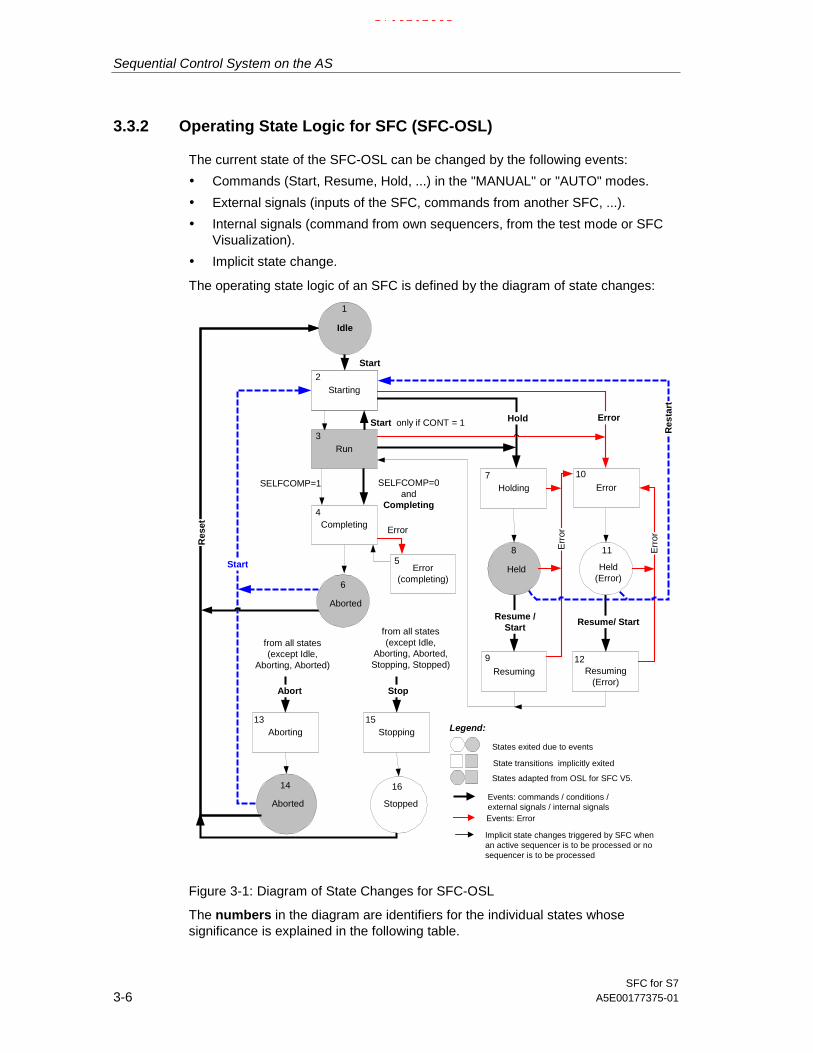
Sequential Control System on the AS
SFC for S73-6 A5E00177375-01
3.3.2 Operating State Logic for SFC (SFC-OSL)
The current state of the SFC-OSL can be changed by the following events:
• Commands (Start, Resume, Hold, ...) in the "MANUAL" or "AUTO" modes.
• External signals (inputs of the SFC, commands from another SFC, ...).
• Internal signals (command from own sequencers, from the test mode or SFCVisualization).
• Implicit state change.
The operating state logic of an SFC is defined by the diagram of state changes:
Aborting
from all states(except Idle,
Aborting, Aborted)
Start
ErrorHolding
Resuming(Error)
Resuming
Resume /Start
STARTING
Completing
Stopping
from all states(except Idle,
Aborting, Aborted,Stopping, Stopped)
Err
orError
Starting
Idle
Hold
Error(completing)
Err
or
Start
Run
1
2
3
4
13 15
14 16
7 10
8 11
9 12
5
Error
States exited due to events
State transitions implicitly exited
Events: commands / conditions /external signals / internal signals
Implicit state changes triggered by SFC whenan active sequencer is to be processed or nosequencer is to be processed
States adapted from OSL for SFC V5.
Events: Error
Legend:
Completed
Res
tart
Held(Error)
Resume/ Start
SELFCOMP=1 SELFCOMP=0and
Completing
Res
et
Abort Stop
Start only if CONT = 1
Aborted Stopped
Aborted
6
Held
Figure 3-1: Diagram of State Changes for SFC-OSL
The numbers in the diagram are identifiers for the individual states whosesignificance is explained in the following table.
17.02.200317.02.200317.02.2003

Sequential Control System on the AS
SFC for S7A5E00177375-01 3-7
Operating States (SFC-OSL)
Table 3-2: Operating States: SFC
No. Status Meaning
1 Ready Basic state; waiting for start command.
2 Starting Processing start after start command.
3 Active Normal execution after completing startup.
4 Completing Completing execution after the complete command orimplicit completion.
5 Error (completing) Error processing during completion.
6 Completed Final processing completed; waiting for reset or startcommand.
7 Holding Processing hold after hold command.
8 Held Hold processing completed; waiting for resume command.
9 Resuming Processing resume after resume command.
10 Error Error processing after error.
11 Held (error) Error processing completed and error no longer present;waiting for resume command.
12 Resuming (error) Processing resume after resume command.
13 Aborting Processing abort after abort command.
14 Aborted Abort processing completed; waiting for reset or startcommand.
15 Stopping Processing stop after stop command.
16 Stopped Stop processing completed; waiting for reset command.
For more information on the state changes and state control via SFC I/Os, refer tothe SFC online help, topic "Operating State Logic for SFC".
17.02.200317.02.200317.02.2003

Sequential Control System on the AS
SFC for S73-8 A5E00177375-01
3.3.3 Operating State Logic for Sequencers (sequencer OSL)
The processing of sequencers is controlled by the sequencer OSL.
The sequencer OSL is run through independent of the SFC-OSL when asequencer executes. This means that the sequencer has a state that must bedistinguished from the state of the SFC. The SFC-OSL can, for example, be in the"holding" state, whereas (due to the processing of the sequencer for the "holding"state), the sequencer OSL is in the "active" state. The processing of the sequencerOSL is subject to the SFC OSL so that state changes in the SFC OSL usuallymean a state change in the sequencer OSL.
The operating state logic of the sequencer is defined by the diagram of statechanges for the sequencer OSL:
Hold
Start
Start
Start
Abort
completed
Idle
Run
Completed
1
2
3
45
States exited due to commands
Operator commands
Implicit state changes triggered by SFC
Legend:
Aborted HeldResume
Restart
Figure 3-2: Diagram of State Changes for Sequencer OSL
17.02.200317.02.200317.02.2003

Sequential Control System on the AS
SFC for S7A5E00177375-01 3-9
The states of the sequencer OSL
Table 3-3: Operating States: Sequencers
No. Status Meaning
1 Ready Basic state; waiting for start command.
2 Active Normal execution.
3 Completed Normal execution completed; waiting for reset or startcommand.
4 Held Hold processing completed; waiting for resume command.
5 Aborted Abort processing completed; waiting for reset or start command.
17.02.200317.02.200317.02.2003

Sequential Control System on the AS
SFC for S73-10 A5E00177375-01
3.3.4 Commands
With the following commands, you can set or modify the operating states of theSFC (in the test mode or in SFC Visualization):
All commands are permitted both in the "AUTO" and in the "MANUAL" mode; in the"MANUAL" mode, they do, however, depend on a command enable.
If several commands are pending at the same time (for example, external andinternal commands), an interconnection error is displayed (LI_ERR=1). How thecommands are then processed, is described in the SFC online help, topic "Priorityof the Commands".
Table 3-4: Commands for the SFC
Button Command Meaning
Start Trigger start processing by changing to the"Starting" state.
Hold Trigger hold processing by changing to the"Holding" state.
Resume Trigger resume processing by changing to the"Resuming" or "Resuming (error)" state.
Abort Trigger abort processing by changing to the"Aborting" state.
Complete Trigger complete processing by changing to the"Completing" state.
Stop Trigger stop processing by changing to the"Stopping" state.
Restart Trigger start processing by changing to the"Starting" state.
Reset Change to the"Ready" state.
Error Trigger error processing by changing to the"Error" or "Error (completing)" state.
Table 3-5: Commands for the Sequencer
Command Meaning
Start / Resume Trigger or resume sequencer execution by changing to the "Active" state.
Hold Hold sequencer execution by changing to the "Held" state.
Restart Restart sequencer execution by changing to the "Active" state.
Abort Abort sequencer execution by changing to the "Aborted" state.
17.02.200317.02.200317.02.2003

Sequential Control System on the AS
SFC for S7A5E00177375-01 3-11
3.3.5 Sequencer Execution
In the following description of the basic principles of cyclic execution of an SFC, itis assumed that the SFC contains several sequencers with freely defined startconditions.
Sequence
The execution of the SFC depends on the input signals applied to the SFCinterface and the internal status of the SFC. After downloading a chart folder to theprogrammable controller, all the SFCs are in the "Ready" state.
• The mode, commands, and external and internal signals are queried toestablish how the SFC will execute, in other words, which state the SFC shouldadopt based on the input signals.
• All the start conditions of the sequencers are checked to determine whichsequencer will execute on the basis of the checks made up to now.
SFC State Unchanged
If the SFC state is unchanged, the sequencer that will execute is the one whosestart condition is satisfied and that has the highest priority of all sequencers with asatisfied start condition. If there are several sequencers with a satisfied startcondition and the same priority, then (analogous to the execution of alternativesequences) the sequencer with the tab furthest left in the editor will execute. If thesequencer that was executing is different from the newly selected sequencer, theprevious sequencer aborts and the new sequencer starts.
The start condition triggers the start of a sequencer. While the sequencerexecutes, it is not necessary for the start condition to remain satisfied. Thesequencer executes until it is completed or until a sequencer with a higher priorityand satisfied start condition needs to execute or until the sequencer is aborted orheld due to a status change.
In the "Ready", "Completed", "Aborted", "Stopped", "Held", "Held (error)", "Error"and "Active" states (when SELFCOMP=0), sequencers execute until the state isexited due to a command. As a result, a sequencer is repeated any number oftimes if the start condition is satisfied and there is no command applied. If you wantto avoid this, the last transition of the sequencer must be configured with anunsatisfied condition. As a result, the sequencer "hangs" at this transition and thisstate is exited only with a command.
17.02.200317.02.200317.02.2003

Sequential Control System on the AS
SFC for S73-12 A5E00177375-01
SFC State Changed
If the SFC state has changed, the SFC executes the previous and the newsequencer depending on the state change that occurred, as follows:
If the state change is from "active" to "holding", the previous sequencer is held oraborted (depending on RUNHOLD) and the new sequencer starts.
There is a state change from "resume" or "resuming (error)" to "active" when theprevious sequencer has executed to completion. The new sequencer resumes orstarts at the change from "resuming" (depending on RUNHOLD) and starts at thechange from "resuming (error)".
If there is an implicit state change, the change of sequencer takes place when thefirst sequencer is completed. If there is no sequencer with a satisfied startcondition, the implicit change is made immediately and the new sequencer isstarted.
With all other state changes resulting from commands, external or internal signals,the previous sequencer aborts if it has not yet completed and the new sequencerstarts.
Notes
• When a sequencer aborts, the active steps always execute completely andthen the final step executes. The completion of the active steps and theinitialization or execution of the final step take place in one cycle.
• In an SFC, a sequencer can execute even if the SFC has not received a startcommand. This is the situation, for example, when the start condition of one ormore sequencers is satisfied in the "Ready" state or when the start condition isnot dependent on states.
Target Step for the Sequencer
the start response of a sequencer that will become active in the future can beinfluenced by setting a target step for this sequencer in step actions of the currentlyactive sequencer (SFC.TARGETSEQ:=2; SFC.TARGETSTEP:=5). Thiscorresponds to setting a target step manually during testing and commissioning,the difference in this case is, however, that all other target steps including those setmanually are reset. This means that the required initial step is specified for thesequencer that will start later.Please note that target steps cannot be set in simultaneous sequences.
A target step is taken into account when a sequencer starts or resumes and is thendeleted.
Since the required execution and also the target step generally depend on theprevious execution of the SFC, the last active sequencer and the last active stepcan be checked in a transition condition (SFC.LASTSEQ:=3; SFC.LASTSTEP:=2)to allow you to set different target steps depending on how the SFC executed priorto this.
Sequencers and steps are identified by their numbers. These are displayed in theproperties dialogs and can be used to configure target steps.
17.02.200317.02.200317.02.2003

Sequential Control System on the AS
SFC for S7A5E00177375-01 3-13
[S7] The Influence of the Control Strategy
A change in the control strategy is permitted in all states. The state is retained butthe current sequencer is aborted and this is followed by a check to determinewhether a different sequencer should execute. This means that not only a statechange but also a change in the control strategy can influence how an SFC isexecuted.
The processing of the state and control strategy change is handled by theoperating state logic (OSL).
Summary of the Execution of a Sequencer
If you want to put together the processing of the "active" state and the "holding","held", and "resuming" states as an alternative sequence in a sequencer, theRUNHOLD input of the SFC must be set to TRUE. If RUNHOLD is set to FALSE,the mechanism for the sequencer change would not function (a sequencer cannotbe held and then (re)started and then resumed).
17.02.200317.02.200317.02.2003

Sequential Control System on the AS
SFC for S73-14 A5E00177375-01
3.3.6 Starting an SFC (chart or instance)
An SFC stars only when the constraints are satisfied. The start enable must be set(ENSTART=1) and the SFC must be in a state in which starting is permitted. Thefollowing conditions must also be met:
• There is no interconnection error (LI_ERR=1).
• None of the signals INTERROR, LOCKERROR, LOCKCOMPLETE,LOCKHOLD, LOCKABORT or LOCKSTOP is active at the same time.
• There is no operator error (OP_ERR=1) in the MANUAL mode.
For an SFC instance, when using control strategies, one of the defined controlstrategies (CS=<defined control strategy>) must be selected. If CS==0 orCS>CS_HL, it is not possible to start the SFC instance. If no control strategies areconfigured, the I/Os CS, CS_LL, CS_HL are assigned the value 0 duringcompilation and must not be modified.
For an SFC instance, prior to starting in the AUTO mode, parameter transfer(PARAM=1) must be set. The transferred setpoints are then checked and the startdisable is reset (QDIS_START=0) if the parameters could be accepted. The startdisable remains set as long as no parameters have been transferred by settingPARAM. Following a successful start, the start disable is set until the nextparameter transfer.
If one of the conditions listed above is not satisfied, the start disable(QDIS_START=1) is set and the start is not executed and the "Start" button isinoperable.
Starting in the "Active" State
To be able to start in the "active" state, the additional start enable must be set(ENASTART=1) and self completion must be deactivated (SELFCOMP=0).In the AUTO mode, continuous operation must also be activated (CONT=1).
The start condition of the sequencer required to execute in the "active" state mustalso make sure that the sequencer has not already executed to completion(READY_TC=0). This prevents the sequencer being repeated cyclically when thestart condition is satisfied.
When an SFC starts, the ready identifier is reset (READY_TC=0) and is set again(READY_TC=1) on completion of the sequencer executing in the "active" state.
An example of the start condition would then be: RUN==TRUE ANDREADY_TC==FALSE.
17.02.200317.02.200317.02.2003

Sequential Control System on the AS
SFC for S7A5E00177375-01 3-15
3.3.7 Execution of a Sequential Control System
Phases of a StepEach step is divided into three phases (actions):
• Initialization is the action for first-time execution
• Execution is the action for cyclic execution
• Termination is the action for last execution
The schematic shows the phases of a step in conjunction with a successortransition: on the left the elements in the sequencer topology, on the right, thecorresponding phases.
Processing(cyclic execution)
Successor transition notsatisfied
Initialization(first execution)
Termination(last execution)
satisfied
Sx
Tx
Sequencer topology Phases
Figure 3-3: Phases of a Step in Conjunction with a Follow-on Transition
Processing Steps and TransitionsThe initial step is activated when the chart is started without querying conditionsand its actions are executed.
A (normal) step can have the states “active" and “inactive". A step becomes activeafter the preceding transition passes control to it. The actions are then triggeredand executed. A step becomes inactive after the successor transition is satisfied.
If there is an abort, the termination processing of the previously active step isexecuted and the initialization of the final step is started (overlapping in the samecycle).
17.02.200317.02.200317.02.2003

Sequential Control System on the AS
SFC for S73-16 A5E00177375-01
A transition has the states “FALSE" and “TRUE". The state of the successortransition of the active step is queried. If the successor transition is true (thecondition is true), the previous step is deactivated and the next step activated. If aminimum run time is configured, the transition is queried depending on the stepcontrol mode only after a this time has elapsed.
The actions of the final step are executed once only.
S4
S5
active
inactive
active
inactive
not satisfied
satisfied
Initialization
Processing
Termination
Initialization
Processing
Termination
Step S5
Step S4
Transition T4T4
Cycles
Actions S4
Actions S5
Figure 3-4: Time Response in Executing Steps and Transitions in a Sequential Control System
When the chart progresses from one step to the next, the predecessor step isterminated in the same cycle as the first action (initialization or execution) of thenext step. This allows the “non-latching behavior" specified in IEC 1131 - 3 to beachieved.
Example: In step S4, the execution opens a valve and in the termination phasethis is closed again. If the same valve is opened again in the first action of the nextstep (S5), the overlapping of the two actions (both in one cycle) means that thevalve is not closed.
17.02.200317.02.200317.02.2003

Sequential Control System on the AS
SFC for S7A5E00177375-01 3-17
Special SituationsThe example in Figure 3-4 shows the response when all three actions of a step areconfigured.
Other combinations are also possible:
• If no “initialization" is configured, the execution begins immediately when thestep is activated.
• If no “termination" is configured, the step is deactivated immediately when thetransition is true.
The minimum time in which a step is active depends on the number of configuredactions (for normal steps 1 to 2 processing phases, with the final step up to 3). If aminimum run time is set for a step, the step remains active for at least this timeeven if the transition condition is satisfied earlier.
Processing a Simultaneous SequenceThe simultaneous sequence paths are executed more or less simultaneously inone cycle (in other words, the entire simultaneous sequence). The simultaneoussequence paths are executed independent of each other.
The transition after the simultaneous sequence becomes true when all steps at theend of the sequence paths are active and the conditions are satisfied.
Processing an Alternative SequenceThe path of an alternative sequence that is executed is the sequence with thetransition whose condition is true first.
If several conditions are true at the same time, the transition furthest left in thechart topology is activated.
Note:In alternative sequences, there must not be no transition without parameters at thestart of a sequence path.Reason: Transitions without parameters are always TRUE and are thereforeautomatically satisfied. This means that they are always true before a transitionwith parameters.
17.02.200317.02.200317.02.2003

Sequential Control System on the AS
SFC for S73-18 A5E00177375-01
Processing a LoopFigure 3-5 illustrates the phases of a loop: To the left the elements in the charttopology, to the right the corresponding phases.
Initialization
Processing
Successor transition
Loop transition
Termination
Termination
satisfied
not satisfied
not satisfied
Figure 3-5: Phases of a Loop
Processing a JumpThe jump is executed when the transition of the jump is satisfied.
S8 S9 S8 S9
T5
T6
T7
T8
S5 S6
Alternativesequence
Successor transition
T4
S4S4
Jump
Figure 3-6: Example: Jumps from a Successor Transition and an Alternative Sequence
If there is more than one jump following the origin of a jump (S4), then (just as inalternative sequences), the jump whose transition is satisfied first is executed. Ifseveral transitions are true at the same time, the transition furthest left is activated.If the next element in the sequence is not a successor transition (such as T4 on theleft in Figure 3-6 but an alternative sequence, all the transitions of the alternativepaths (T5 and T7) are queried before the transitions of the jumps.
17.02.200317.02.200317.02.2003

SFC for S7A5E00177375-01 4-1
4 Test and Startup
OverviewTo support you when you put a new program into operation, the SFC editorprovides test functions that allow you to monitor the operation of the charts on theCPU, to control the running of the chart, and to change settings.
This chapter describes how to monitor and control the sequential control systemwhen testing.
4.1 Activating the Test
Requirements for TestingThe sequential control system (chart or instance) to be tested and the basic controlfunctions (CFC charts) must be loaded on the CPU.
The chart is opened in SFC or the SIMATIC Manager, the SFC instance in theCFC chart.
[S7] The Modes for TestingBefore you switch over to testing, you can select between the "process mode" andthe "laboratory mode".
In the process mode, the communication for online dynamic display of the SFCsis restricted and causes only limited extra load on the CP and bus. If overloadoccurs in this test mode, a message is displayed to indicate the limit of bus loadhas been reached. In this case, you should stop the testing of the SFCs that arenot absolutely necessary for the test.
The laboratory mode allows convenient and efficient testing and commissioning.In the laboratory mode, in contrast to the process mode, communication for onlinedynamic display of SFCs is unrestricted.
You set the mode for testing with the menu commands “Debug > Process Mode" or“Debug > Laboratory Mode".
17.02.200317.02.200317.02.2003

Test and Startup
SFC for S74-2 A5E00177375-01
Switching over to the Test Mode
You change from the edit mode to the test mode by clicking the button in thetoolbar or by selecting the "Debug > Test Mode" menu command. During the Testmode, you can change to the Edit mode at any time.
The mode change relates to the currently active SFC. This SFC is displayeddynamically in its overview and is cyclically updated (you can set the watchingcycle with the “Debug > Test Settings..." menu command.)
Note:If you change the test settings, you change the watching cycle for all charts of thisCPU.
After you change to the Test mode, the current state of the chart is displayed. Thismeans that a sequential control system that has already started cannot always bemonitored or controlled from the start. This is, for example, the case with chartsthat are started immediately after they are downloaded to the CPU without anyoperator command being required (autostart).
[S7] Note on H CPUs: If the H CPU is in the solo mode, for example after thefailure of a CPU and there was a CPU failover, an online access (in this case,download) results in a dialog being displayed. In this dialog, you can select therequired CPU. In the redundant mode, this dialog does not appear.
17.02.200317.02.200317.02.2003
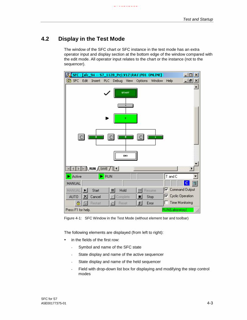
Test and Startup
SFC for S7A5E00177375-01 4-3
4.2 Display in the Test Mode
The window of the SFC chart or SFC instance in the test mode has an extraoperator input and display section at the bottom edge of the window compared withthe edit mode. All operator input relates to the chart or the instance (not to thesequencer).
Figure 4-1: SFC Window in the Test Mode (without element bar and toolbar)
The following elements are displayed (from left to right):
• in the fields of the first row:
- Symbol and name of the SFC state
- State display and name of the active sequencer
- State display and name of the held sequencer
- Field with drop-down list box for displaying and modifying the step controlmodes
17.02.200317.02.200317.02.2003

Test and Startup
SFC for S74-4 A5E00177375-01
• in the fields of the second row:
- The current mode (MANUAL / AUTO)
- "CONTINUOUS" state flag for smooth switchover (for example, inSIMATIC BATCH to avoid having to turn off the SFC being used whenchanging from one recipe operation to another. Displayed when the CONTinput is set to 1.
- Status display "READY T.C." when the SFC is not self terminating(SELFCOMP = 0) and waits for the "complete" command in the activestate.
- The display for an interconnection error (or empty field)
- The display for an operator error (or empty field)
- The display for a step error (or empty field)
- The display for an operator prompt (or empty field)
- The Confirm All button
• The Buttons
- for selecting the "MANUAL" or "AUTO" mode
- for enabling the switchover to "AUTO" .
When this has been enabled, the button changes to .
• The buttons for the commands:
Start Hold Resume
Abort Complete Stop
Restart Reset Error
• The check boxes for activating and deactivating the execution options"command output", "cyclic operation", "time monitoring".
Operator PromptThe operator prompt (not with step control mode “T") is displayed in a box besidethe transition icon.
After clicking on the field (or ) and continuing execution, the operator promptdisappears again.
17.02.200317.02.200317.02.2003

Test and Startup
SFC for S7A5E00177375-01 4-5
Displaying the States
In the test mode of the SFC, both the SFC and the sequencers with their startconditions are made dynamic. The current states of the SFC and sequencer aredisplayed in the operator input and display section of the SFC (see above).
The various states of the sequential control system, the steps, the transitions arevisualized by different colors and icons.
In addition to the color frame of the steps, a status display also appears. The iconof the status display is therefore an additional indicator of the current states in thechart in case the colors cannot be clearly distinguished. The colors of the statedisplays cannot be changed.
Table 4-1: Appearance of the State Displays
Step state Step color Symbol
inactive (not executed) gray
inactive (executed) dark green
active light green
held yellow
error red
Transition State Transition Color
inactive gray
satisfied dark red
not satisfied dark green
Display of the CPU modeThe operating mode of the CPU is displayed in the status bar (right informationbox) in color (green = RUN, red = STOP). The test mode (Laboratory) or (Process)is also indicated.
17.02.200317.02.200317.02.2003

Test and Startup
SFC for S74-6 A5E00177375-01
4.3 Operator Control and Monitoring of the SequentialControl System
Setting the Test EnvironmentWith the "Debug > Test Settings..." menu command, you can open a dialog box inwhich you can change the watching cycle for the current program (default 2 s). Youcan set cycles from 1 to 9 and in steps of ten from 10 to 90 seconds.
The same cycle time as for CFC is stored in the chart folder. This means that thesame monitoring cycle is valid for both applications (SFC and CFC).
Operator Control and MonitoringYou operate and monitor the SFC in the overview display. Here, you can changethe statuses, modes, step control modes, and the chart options as required.
This always relates to the sequencer in the foreground selected by its tab; in otherwords, there is no implicit changeover to the current sequencer.
If you double-click on a step or a transition, a dialog box appears resembling theobject properties dialog in the Edit mode. You can also display the objectproperties for step and transition at the same time by selecting the requiredtransition and opening both dialog boxes by double-clicking a step (or the otherway round by selecting a step and double-clicking the transition). To be able to seeboth dialog boxes at the same time, the step and transition do not need to belongtogether.
A selected element is indicated by a blue background.
Confirming in the Sequencer and in the Object Properties DialogIf a button is displayed for operator intervention or to confirm an error for themonitored step or transition in the sequence path, the dialog box with the objectproperties also has the corresponding button or buttons added to it.
Note: After a step run-time error has been acknowledged, the appearance of thestep returns to the state before the error occurred (for example active = “lightgreen").
Changes during a Test Run (SFC chart only, not SFC instance)
The step attributes (confirmation, minimum/maximum run time, constant inassignments) and transition attributes (constant in conditions) that can be modifiedin the Test mode are adopted on the AS and in the ES data management when thechange is made and do not require recompilation and download.
Note: If you want to modify the existing SFC instances, you must exit the testmode and then modify the corresponding SFC type. After compiling the changesand downloading them, all the instances are automatically adapted.
17.02.200317.02.200317.02.2003

Test and Startup
SFC for S7A5E00177375-01 4-7
4.3.1 The Object Properties of a Step during Testing
The Properties dialog is divided into four parts. These are the tabs: “General",“Initialization", “Processing" and “Termination".
• “General" Tab
The “Name" box in the “General" tab is in a frame, the frame color correspondsto the operating state of the step and is updated constantly (colors: see table in“Default Colors" in the online help).
You can activate or deactivate the “Confirmation" option and which sets orresets a flag that is evaluated in the “T / T and C" step control mode (step-specific confirmation by user). The sequential control system operates asfollows:
- process-controlled for steps without the “Confirmation" option.Each satisfied successor transition of a step without the “Confirmation"option passes control without operator intervention (corresponds to “T").
- operator-controlled for steps with the “Confirmation" option.If the successor transition of an active step with the “Confirmation" option issatisfied, an operator prompt is set and control passes to the next step orsteps after the prompt has been confirmed (corresponds to “T and C").
[S7] By setting the "Target step" option, the current step is selected as thetarget step. This means that
- The stopped sequencer starts at the selected target step instead of at theinitial step with the next "Start" command.
- the held sequencer resumes at the target step after correct processing ofthe interrupted steps when the “Continue" command is set.
[S7] The target step marker is valid only for the next “Start" or “Continue"command. When you restart the CPU, the target step marker is deleted.
You can also select several steps as the target steps. The user is responsiblefor selecting the target steps so that the processing is feasible; in other word,that no blockages or endless loops result. See also Section 3.3.5, EditingSequencers.
If you use "programmed target steps", the target steps sent by the operator inthe corresponding sequencers are deleted.
You can change the values of “Run Times Minimum" and “Run TimesMaximum". By clicking in the input box, you open a dialog in which you canchange the current setting. Any changes you make are entered in the ES datamanagement when you confirm with OK and take effect in the next processingcycle.
With the boxes “Run Times - Current", “Time to minimum" and “Time tomaximum" you can monitor the run time.If no values were configured for the run times (time = 0), then “- - -" is displayedin the boxes.
• "Initialization, Processing, Termination" Tabs
The current value of the 1st address is shown in a box to its left. The field to
17.02.200317.02.200317.02.2003

Test and Startup
SFC for S74-8 A5E00177375-01
the right beside the 2nd address contains the current setpoint that you canmodify (SFC chart only). If you click the box, you open the “Change Value"dialog box, in which you can enter the new value.
After you close the dialog box, the changed value is written to the ES datamanagement and becomes effective in the next processing cycle.
If the monitoring of the step detects a time error, the confirm button is addedto the buttons This allows you to acknowledge the error from the dialog box.
After a step run-time error has been acknowledged, the appearance of the stepreturns to the state before the error occurred (for example active = “light green").
Using the “Go To" button, you can jump from the current field of an operand to itspoint of use (block in the CFC chart, SFC chart, I/O address in HW Config.).
17.02.200317.02.200317.02.2003

Test and Startup
SFC for S7A5E00177375-01 4-9
4.3.2 The Object Properties of a Transition during Testing
The Properties dialog of a transition is divided into four parts. These are as follows:
• GeneralThe “Name" box in the “General" tab is in a frame, the frame color correspondsto the operating state of the step or transition and is updated constantly (colors:refer to the table in “Default Colors" in the online help).
• The current condition (Current Cond.)shows the current state of the conditions
• The last condition ("Current Cond. -1")shows the state of the condition of the previous execution cycle.
• The condition after error ("Cond.after Error")shows the state of the condition that led to an error.
Changing AddressesTo the left of the first address and to the right of the second address there arefields with the current value of the address. In the SFC chart, you can change thecontent of both fields (not possible with an SFC instance). If you click one of theboxes, the “Change Value" dialog box is displayed in which you can enter a newvalue for the address.
After you close the dialog box, the changed value is written to the ES datamanagement and becomes effective in the next processing cycle.If there is an operator prompt for the monitored transition in the sequencer and thebutton displayed beside the transition, the dialog box with the object properties alsohas this button added to it. This allows you to acknowledge the operator promptfrom the dialog box.
Using the “Go To" button, you can jump from the current field of an operand to itspoint of use (block in the CFC chart, SFC chart, I/O address in HW Config.).
Status of the Logic OperationThe results of the logic operations of the conditions using Boolean operators arevisualized as colored links of varying thickness. A broad, green line means“satisfied", a thin, red line means “not satisfied" and a thin, black line means“inactive".
Update
The content is updated continuously in the “Current Cond." tab. In the “CurrentCond. -1" and “Cond. after Error" tabs also include the "Update" button. The stateof the transition is entered here as it was at the time when the object propertieswere opened. Using the “Update" function, you can display the current state in apermanently open dialog box.
17.02.200317.02.200317.02.2003

Test and Startup
SFC for S74-10 A5E00177375-01
17.02.200317.02.200317.02.2003

SFC for S7A5E00177375-01 5-1
5 Documentation
OverviewThis chapter describes how you create the documentation for your SFCcharts/types/instances. This includes printing the SFC in various views and printingthe parameter assignment, the properties, and chart reference data.
5.1 Printing an SFC
You can print the current chart or type by clicking the button in the toolbar orusing the "SFC > Print..." menu command. In the dialog box that opens, you canmake settings relating to the scope of the printout (Print What) and the layout(Options).
Print What: properties, I/Os, external view (with SFC chart) or alternativelycharacteristics (with SFC type/instance). For sequencers: properties, normalsize, overview, steps/transitions. You can select either normal size or overview,but not both.
• Options (only for "normal size"): alternative sequence left-aligned,comment/text.
Note:The selected range is always printed for the entire SFC. If you only require aprintout of a step or a transition, use the print functions of the in the “ObjectProperties" dialog of the selected element.
17.02.200317.02.200317.02.2003

Documentation
SFC for S75-2 A5E00177375-01
5.2 Defining Footers
With the SFC > Footers... menu command, you can open a dialog box in whichyou enter the text printed in the footers of every printed page.
With the DOCPRO optional package, you can print the SFC chart/type along withfooter data. In the footer data, a distinction is made between global data and localdata specific to an SFC.
You can enter the global data for the project using DOCPRO or the SIMATICManager; the local specific data must be entered with the SFC editor. Rememberthat the data specific to an SFC overwrites the entries of the global data for theparticular SFC.
You can also enter specific data even when you have not installed the DOCPROoptional package. This data is saved and can be printed later when DOCPRO isavailable for print jobs.
You can enter the SFC-specific footer data in the active fields of the tabs "Part 1"to "Part 4" and "Free fields". These include the type of document, date created,document number, dates modified, free texts etc.
In the global footers, you can enter keywords that are replaced by the actual textswhen you print out. The keywords that can be used and their meaning (origin) areexplained in the online help of SFC.
5.3 Chart Reference Data
With the "Options > Chart Reference Data..." menu command or by clicking ,you start an application that creates comprehensive documentation listing, forexample, the run sequence, the cross-references of the addresses etc.
With a search function, you can search for specified addresses, symbols, I/Os etc.
This helps you to check your configuration structure. With the “Cross-ReferencesChart Element -> Address" list, you can, for example, check which addresses areused and how often and whether the write access is synchronized.
You do not need to close the window with the chart reference data if you want tocontinue working with the SFC editor. This means that you can view the lists whileworking with the SFC editor.
For a detailed description of the “Chart Reference Data", refer to the CFC onlinehelp.
17.02.200317.02.200317.02.2003

SFC for S7A5E00177375-01 A-1
A Technical Specifications
A.1 Technical Specifications
Hardware Requirements
• PG or PC with:
- Pentium Processor
- RAM 256 Mbytes (or more)
- Hard disk 500 Mbytes (less RAM)
- Graphics card VGA 640 x 480(recommended: SVGA 1024 x 768 or higher)
• SIMATIC S7-400
Software Requirements
• Microsoft Windows NT (SP 5) / Windows 2000 (SP 3)
• STEP 7
• SCL Compiler
• CFC
An authorization for STEP 7, SCL, CFC and SFC must be installed.
General Numeric Data
Object Number
Steps per chart 2 - 255
Transitions per chart 1 - 255
Statements per step and action • 50
Conditions per transition • 16
Sequencers per SFC chart • 8
Sequencers per SFC type • 32
Steps per sequencer 2 - 255
Transitions per sequencer 1 - 255
12.03.200317.02.200317.02.200317.02.2003

Technical Specifications
SFC for S7A-2 A5E00177375-01
12.03.200317.02.200317.02.200317.02.2003

SFC for S7A5E00177375-01 B-1
B Abbreviations
C Step control mode: confirmation by operator
C / C++ High-level language for programming computers
CFC Continuous Function Chart
CPU Central processing unit
DB Data block
ES Engineering system
FB Function block (function block with memory)
FC Function (function block without memory)
HID Higher level designation
IEA Import-Export Assistant
OB Organization block
OCM Operator control and monitoring (WinCC)
OS Operator station
PC Personal computer
12.03.200317.02.200317.02.200317.02.2003

Abbreviations
SFC for S7B-2 A5E00177375-01
PCS 7 Process control system (SIMATIC)
PG Programming device
PH Plant hierarchy
PLC Programmable controller
PLC Programmable logic controller
SFB System function block
SFC Sequential Function Chart
SFV SFC Visualization
STEP 7 Software development environment for SIMATIC S7 / M7
T Step control mode: transition only
T / T and C Step control mode: step-specific confirmation by operator
T and C Step control mode: transition and confirmation by operator
T or C Step control mode: transition or confirmation by operator
12.03.200317.02.200317.02.200317.02.2003

SFC for S7A5E00177375-01 Glossary-1
Glossary
A
AccessSFC elements or block I/Os can access addresses, charts, block I/Os, or run-timegroups. A distinction is made between read and write access.
ActionActions allow the activation or deactivation of run-time group and SFC charts, aswell as modifications to blocks and shared resources and their input parameters.The actions are formulated in SFC in the Properties dialog.
AddressAn address is the identifier of the location of data or an area containing data,examples: input I12.1; memory word MW25; data block DB3. Addresses can bespecified in absolute or symbolic form.
An address is part of a STEP 7 instruction and tells the processor what it shouldperform an operation on.
In SFC, the address is part of a statement (step) or condition (transition).
Addressing, absolute
If data is addressed in absolute form, the absolute ↑address is used to access thevalue with which the operation will be performed. Example: The address Q4.0identifies bit 0 in byte 4 of the process output image (PIQ).
Addressing, symbolic
If data is addressed using symbols, the ↑ address to be processed is specified as asymbol (not as an absolute address). Symbols are assigned to addresses in thesymbol table.
Alternative sequence
A structural element of an SFC, that consists of at least two ↑sequence paths. Onlythe path whose transition condition is satisfied first is processed by the PLC.
12.03.200317.02.200317.02.200317.02.2003

Glossary
SFC for S7Glossary-2 A5E00177375-01
B
Basic control
Basic control is the configuration of the programmable controller (PLC). Theconfiguration tools available are the CFC and SFC editors.
BlockBlocks are separate parts of a user program that are distinguished by theirfunction, their structure, or purpose.
CFC works with ready-made block types that are placed (inserted) in a CFC chart.When a block type is inserted in the chart, a block instance is created. These blockinstances and their graphic representation are blocks in the sense of CFC.
Block categoryThe block category identifies different forms of blocks. Block categories include, forexample, data blocks (DBs), function blocks (FBs), and functions (FCs).
Block icon
Graphic representation of the most important information of a technological, blockthat can be controlled and monitored on the PLC. The block icon is typically placedin an OS overview picture. The corresponding faceplate can be called up using theblock icon.
Block input
Block I/O that can be interconnected with block outputs and ↑ addresses of thesame data type or can have parameters assigned to it.
Block instanceA block instance is the implementation of a block type. A block type inserted in aCFC chart becomes an instance. After it is inserted, the block instance has run-time properties and name that is unique within the chart.
Block I/OBlock input or block output
Block output
Block I/O that can be interconnected with block inputs and ↑ addresses of thesame data type.
12.03.200317.02.200317.02.200317.02.2003

Glossary
SFC for S7A5E00177375-01 Glossary-3
C
Catalog
Window in CFC, that can be switched between the catalogs of blocks, charts,libraries, and unplaced blocks (if unplaced blocks exist). You can insert blocks,charts and text boxes from the catalog into a chart.
CFCContinuous Function Chart.
1. Function chart (CFC chart) with the graphic interconnection of technologicalfunctions (blocks).
2. An editor for plant/oriented, graphic configuration of automation tasks. UsingCFC, entire software structures are created (CFC charts) from ready-madeblocks.
Chart
Depending on the context, a chart in the ES is
• a CFC chart consisting of 1 to 26 chart partitions each with 6 sheets andpossibly also overflow pages.
• a nested chart that results when one chart is inserted in another (chart-in-chart).
• an SFC chart consisting of between 1 and a maximum of 8 tabs. Each tabcontains a sequencer.
Chart elementChart elements of the SFC chart are the basic elements (step, transition, text) andstructure elements (sequence, simultaneous sequence, alternative sequence, loopand jump).
Chart folderFolder in the project structure containing charts of a user program.
Chart reference dataChart reference data is data available to the user in addition to the graphic chartdisplay in the form of lists, for example the list of accesses to shared addresses.
Component viewDevice-oriented view in the SIMATIC Manager. The project is displayed with itscomponents (station, module, program ... );alternative to the ↑ plant view or ↑ process object view.
12.03.200317.02.200317.02.200317.02.2003

Glossary
SFC for S7Glossary-4 A5E00177375-01
Consistency checkChecks the consistency of block types, shared addresses etc. of the chart folder.
ConditionConditions in a transition allow you to do the following:
• to read values of block I/Os or shared addresses
• To logically combine the read values with a constant or another read valueusing Boolean operators (=, >, <, ...)
The result of a condition is a Boolean variable that can be logically combined withthe results of other conditions.
Cycle timeThe cycle time is the time required by the CPU to execute the user program once.
D
Data block (DB)
Data blocks are data areas in the user program containing user data. There areshared data blocks that can be accessed by all logic blocks and instance datablocks that are assigned to a particular FB call. In contrast to all other blocks, theycontain no instructions.
Data typeA data type specifies how the value of a variable or constant is used at a block I/O."BOOL", for example, defines a binary variable; "INT" defines a 16-bit integervariable.
Drag-and-drop
With the drag-and-drop function, you can move, copy and insert objects using themouse.
Using drag and drop:
1. Select the objects by clicking them or by drawing a lasso round them.
2. Position the mouse pointer on an object, press the left mouse button and holdit pressed.
3. If you want to copy, hold down the CTRL key as well (the mouse pointer hasthe "+" symbol added to it).
4. Move the mouse pointer to the required position and release the button - theobjects are inserted.
12.03.200317.02.200317.02.200317.02.2003

Glossary
SFC for S7A5E00177375-01 Glossary-5
Dynamic displayIn the dynamic display, input and output values of a block in a CFC chart oraddress values in an SFC chart are updated from the CPU in the Test mode.
E
Edit mode
(Alternative to the ↑ test mode)In CFC blocks can be inserted, copied, moved, deleted, renamed, have parametervalues assigned, or be interconnected.In SFC the sequential control system is created in this mode. Chart elements canbe inserted, copied, moved, deleted, renamed, and assigned parameters.
ESAbbreviation for "Engineering System". This is a user-friendly, visual configurationsystem in which the process control system can be created and adapted todifferent situations.
External view
The external view is the graphic representation of a SFC chart as block (withinterface) that allows external interconnection of the I/Os. The external viewcontains the standard interface that is derived from the SFC run-time system.
The external view of the SFC can be interconnected with any objects (CFC blocks,nested charts, run-time groups, textual references, shared addresses). This meansthat the SFC chart can also be controlled directly by CFC interconnections.
The external view is displayed in a separate window in the CFC. Other objectscannot be placed in this window. Interconnections to other CFC objects areimplemented solely via the sheet bar.
F
Forced manual switchoverSwitchover by the operator from the "AUTO" mode to the "MANUAL" mode withouta prior enable.
12.03.200317.02.200317.02.200317.02.2003

Glossary
SFC for S7Glossary-6 A5E00177375-01
H
Hierarchy folder
The hierarchy folder is used to structure the plant in a hierarchy. It can containfurther hierarchy folders and objects such as CFC / SFC charts, process pictures,reports, additional documents (Excel, Word, ...). The HID of an object is obtainedfrom the name of the hierarchy folder (path) and the object name.
Higher level designation (HID)The HID is used to identify parts of a plant according to their functions. This ismade up of the hierarchical path of the plant hierarchy.
I
Installation and startupThe CFC/SFC editors provide test functions to allow you to monitor, modify, andchange parameter settings on the PLC during installation and startup.
Installing
Procedure with which a block/SFC chart is placed in a ↑ run-time group so that it isregistered with an ↑ organization block (OB).
InstanceWhen you insert an SFC type or a block type in a CFC chart, an instance iscreated. Instance in this sense means that it is an instance or usage of theselected SFC type or block type.
InterconnectionIn CFC, the connection of an I/O to another element. The value of theinterconnected input is fetched from the other end of the interconnection during runtime. Read or write access from an SFC chart to a block I/O in a CFC chart is alsoknown as an interconnection.
I/OThe input or output of a block or chart. I/Os of the same data type can beinterconnected or connected to shared addresses. An I/O is parameter, thataccepts data for further processing (input) and transfers the resulting data (output).
12.03.200317.02.200317.02.200317.02.2003

Glossary
SFC for S7A5E00177375-01 Glossary-7
J
JumpA jump is a structure element of SFC, with which the execution of an SFC can becontinued at a different step in the same SFC depending on a transition condition.
L
Laboratory mode
One of the test modes.The laboratory mode allows convenient and efficient testing and commissioning. Inthe laboratory mode communication for online dynamic display of SFCs isunrestricted.
As an alternative to the laboratory mode, you can also select the ↑ process mode(restricted test mode). It is not possible to switch over between the process andlaboratory modes when testing is active (only in the edit mode).
LibraryA folder for objects that can be used again and again. A library is not project-related. Blocks are made available in block libraries sorted according to certaincriteria (block families, alphabetical order etc.). Different block libraries are useddepending on the PLC or situation.
Loop
Structure element in SFC consisting of a ↑ sequence and a return path; thesequence encloses and contains exactly one transition.
M
Master project
A master project is a project that has had parts of it (for example, charts)distributed into other projects (branch projects) to allow more efficient engineering.After they have been worked on, the parts are merged back into the original project= master project.
Messages, configuringCreating messages with their attributes and texts. Messages can be configuredfrom within SFC.
12.03.200317.02.200317.02.200317.02.2003

Glossary
SFC for S7Glossary-8 A5E00177375-01
Mode1. CPU:Using the mode selector of the CPU, you can set the following operating modes:
• RUN with access to the STEP 7 user program,for example, with programming device ("RUN-P"),
• RUN with access protection ("RUN"),
• STOP and
• Memory Reset ("MRES").
2. SFC:The mode decides how the execution of an SFC is controlled.
• AUTO (process mode): Execution is controlled automatically, for example, viathe external view of an SFC chart..
• MANUAL (operator mode): Execution of the chart is controlled manually by anoperator, for example during commissioning or with SFV (SFC Visualization inWinCC).
O
Online/offline
In the SIMATIC Manager, objects of the programmable controller are displayed inthe online view and the objects of the ES in the offline view. Online, there is a dataconnection between the PLC and the programming device/PG, offline there is noconnection.
Operating mode
1. The programmable controllers of SIMATIC S7 can adopt the followingoperating modes: STOP, STARTUP, RUN and HOLD.
2. SFC has the following operating states Ready, Starting, Active, Completing,Error (completing), Completed, Holding, Held, Continuing, Error, Held (error),Resuming (error), Aborting, Aborted, Stopping, Stopped.
Operating systemGeneral term for all the functions that control and monitor the execution of the userprograms, the distribution of resources to the individual user programs, and themaintenance of the operating mode in conjunction with the hardware (for examplestandard operating system MS-WINDOWS).
12.03.200317.02.200317.02.200317.02.2003

Glossary
SFC for S7A5E00177375-01 Glossary-9
Operating state logic (OSL)
The operating state logic of SFC describes
• the states that can be adopted by an SFC chart or an SFC instance.
• the state changes possible in a particular state.
• the events that bring about a state change.
In addition to the SFC-OSL, there is also a separate simpler operating state logicfor the sequencers, the sequencer OSL. This describes the states that can occur ina sequencer.
Organization block (OB)Organization blocks form the interface between the operating system of the CPUand the user program. The order of execution of the user program is specified inorganization blocks.
An organization block corresponds to a ↑ task.
OSOperator Station. A station for controlling and monitoring the process. In PCS 7,the WinCC software system is used for the OS with which all the processmonitoring and control functions can be implemented.
P
Phase offset
The phase offset shifts the point of activation of the run-time group within a task bya defined time compared with the basic cycle. Phase offset allows a uniformdistribution of load within the CPU. See also ↑ scan rate.
Plant Hierarchy (PH)A hierarchy structured according to technological aspects.
Plant viewView in the SIMATIC Manager based on technological aspects (plant (processcell), unit, function ...); alternative to the ↑ component view and ↑ process objectview.
12.03.200317.02.200317.02.200317.02.2003

Glossary
SFC for S7Glossary-10 A5E00177375-01
PostprocessingA cyclic action can also be configured for each sequencer. The cyclic actionconsists of a part that is executed before the cyclic sequencer processing, thepreprocessing and a part that is executed after the cyclic sequencer processing,the postprocessing.
Preprocessing
See ↑ Postprocessing.
Process
Sequence of chemical, physical, or biological processes for extraction, productionor elimination of substances or products.
Process imageReserved areas in the RAM of the CPU. Signal states of the input and outputmodules are entered here.
Process modeOne of the test modes. In the process mode, the communication for online dynamicdisplay of the SFC charts is restricted and causes only limited extra load on the CPand bus.
As an alternative to the process mode, you can also select the ↑ laboratory mode(unrestricted test mode).
Processing phaseA step is divided into three processing phases: initialization, (cyclic ) processingand termination. Each processing phase corresponds to an action with statements.
Process object view
View in the SIMATIC Manager. With the process object view, all the data of thebasic control of an entire project can be displayed in process control-oriented view.
Process tagA neutral object in terms of resources. It is used to connect the PLC configurationworld (STEP 7, CFC ...) with the OS configuration world (WinCC). It containsinformation about its location during run time (for example the network address andthe memory area on the PLC) as well as information on specific OS-relevantproperties.
12.03.200317.02.200317.02.200317.02.2003
Glossary
SFC for S7A5E00177375-01 Glossary-11
Programmable (Logic) controller (PLC)A programmable controller a SIMATIC S7 PLC, a complete device (PLC withintegrated operator panel) in SIMATIC C7 or an automation computer in SIMATICM7. It is used for closed and open-loop control of processes in process engineeringand manufacturing.
PLC is used as a general term for the unit containing the CPUs on which the userprogram runs. In this case, it includes S7 programmable controllers and M7automation computers.
ProjectA folder for all the automation solutions regardless of the number of stations ormodules and how they are networked.
R
RecipeA recipe is the procedure for manufacturing a product according to a specificprocedure.
Resources
Resources are pools of objects (FBs, FCs, DBs, OBs, bit memory, counters, timersetc.) that can be accessed when configuring and setting parameters for aCFC/SFC chart.
Run-time attributeRun-time groups have run-time attributes that control their activation. All the blocksand/or SFC charts in a run-time group inherit these attributes from it.
In S7 the tasks are implemented as ↑ organization blocks (OBs).
Run-time groupRun-time groups are used to structure tasks. The blocks and/or SFC charts areinstalled in the run-time groups. Run-time groups have run-time attributes and canbe activated and deactivated separately by interconnecting them with a blockoutput or by a statement. If a run-time group is deactivated, none of the objects itcontains will be activated any longer.
Run-time propertiesThe run-time properties of block or SFC chart determine how the block/chart isincluded in the execution of the entire structure on the PLC. These properties arevital to the performance of the PLC in terms of reaction times, dead times, or thestability of time-dependent structures, for example control loops.
12.03.200317.02.200317.02.200317.02.2003

Glossary
SFC for S7Glossary-12 A5E00177375-01
Run sequenceThis is a program sequence with which the blocks and/or SFC charts can beinstalled in the order in which they are executed by the CPU. The run sequence isdisplayed as a separate window in CFC and contains the OBs of the relevant PLC.
S
S7 program
A folder for the ↑ symbol table, the blocks, the source files, and the charts for theprogrammable S7 modules.
Scan rate
The scan rate is a ↑ run-time attribute. It specifies whether a ↑ run-time group isexecuted every time a task is executed or only every nth time. See also ↑ phaseoffset.
SCLA high-level language similar to Pascal complying with IEC 1131-3 forprogramming complex solutions on a PLC, for example algorithms and dataprocessing jobs.
Sequence
Structure element in SFC containing a sequence of ↑ steps and ↑ transitions.
Sequence path
In SFC, a sequence path is a series of elements (in the topology seen as a verticalpath). A simultaneous sequence or an alternative sequence consists of at least twosequence paths arranged side-by-side and containing at least one element.
In SFC, an entire ↑ sequencer can also be understood as a sequence path.
SequencerA sequencer is a functionally self-contained unit within a sequential control system.It consists of a series of steps and transitions and begins with an initial step andends with a final step. Within the SFC, a maximum of 8 (chart) or 32 (type)sequencers can be created and selected using tabs.
Sequencer topologyIn the sequencer topology of the SFC, the elements are displayed according tofixed syntax rules (for example, order, spacing, extent and alignment of theelements). When the topology is created, the syntax rules are adhered toautomatically by the editor.
12.03.200317.02.200317.02.200317.02.2003

Glossary
SFC for S7A5E00177375-01 Glossary-13
Sequential control systemA sequential control system switches from one to the next step dependent onconditions. Sequential control systems are implemented in PCS 7 with SFC charts(with up to 8 sequencers) or SFC types (with up to 32 sequencers).
Shared address
Shared addresses are I/O signals (input/output bits, bytes, words, double words;peripheral input/output bits, bytes, words, double words), memory bits, timers,counters, data block cells, functions, or function blocks. They can be accessed inabsolute and symbolic form by SFC and CFC.
Symbolic access uses names (the symbol) of the shared address in the symboltable. For absolute access, the symbol table is not required. The absolute form ofthe shared address is entered. Symbolic addressing has the advantage that theconnection is retained if the address is changed and the symbol stays the same.
When accessing addresses, make sure that the shared address has the same datatype as the block I/O in the CFC chart or statement / condition in the SFC chart.
SFC
An SFC chart is a ↑ sequential control system that runs as a separate controlsystem within the programmable controller.
SFC instance
See ↑ Instance.
SFC type
See ↑ Type.
SIMATIC ManagerGraphic user interface for SIMATIC users under Windows 95/98/NT/2000/XP. TheSIMATIC Manager is used, for example, to create projects and access libraries.
Start conditionThe start condition triggers the start of a sequencer. While the sequencerexecutes, it is not necessary for the start condition to remain satisfied. Thesequencer executes until it is completed or until a sequencer with a higher priorityand satisfied start condition needs to execute or until the sequencer is aborted orheld due to a status change.
12.03.200317.02.200317.02.200317.02.2003

Glossary
SFC for S7Glossary-14 A5E00177375-01
StatementWithin the action of a step, a statement can be used for the following:
• to write to CFC block I/Os
• to assign shared addresses
• to activate and deactivate SFC charts
• to activate and deactivate run-time groups
A statement always consists of a left (first) address, an operator and a right(second) address.
Step
The step is an element of a ↑ sequential control system and is the control instancefor the execution of the associated ↑ actions. A step is divided into threeprocessing phases: initialization, (cyclic ) processing and termination.
Step control modeAn SFC can be executed in various step control modes. These affect the way inwhich the execution of the steps is enabled. You can select the following modes:
• C = confirmation by operator The sequential control system runs controlled bythe operator.
• T = transition. The sequential control system runs controlled by the process.
• T or C = transition or confirmation by operator The sequential control systemruns controlled by the process or by the operator.
• T and C = transition and confirmation by operator The sequential controlsystem runs controlled by the process and by the operator.
• T / T and C = step-specific confirmation by operator. The sequential controlsystem runs process-controlled in steps without the "confirmation" flag (as in"T") and must be confirmed by the operator at steps with the flag (as in "T andC").
Step typesAn SFC has different types of steps: initial step, normal step, final step.
Structure
A structure is a structured ↑ data type made up of various elements. An elementcan be an elementary or a structured data type.
Structure elementStructure elements in SFC consist of an arrangement of basic elements. Structureelements are: "Sequence", "Simultaneous sequence", "Alternative sequence","Loop" and "Jump".
12.03.200317.02.200317.02.200317.02.2003

Glossary
SFC for S7A5E00177375-01 Glossary-15
SymbolA symbol is a name defined by the user according to certain syntactical rules. Afterits purpose has been defined (for example to represent a variable, data type, jumplabel, block), it can be used in programming and in operator monitoring and control.
Example: address : I5.0, data type: BOOL, symbol: Emer stop.
Symbol tableTable for assigning symbols (= name) to addresses for shared data and blocks.Examples: Symbol Address
Emerstop I1.7,Ctrller FB24
T
Target stepIn the test mode (or in SFC visualization on the OS), a step can be selected as thetarget step. This means that the deactivated ↑ sequencer begins again at theselected step instead of the initial step at the next "Start" command and a haltedsequencer resumes at the target step after completing execution of the interruptedstep(s) when the "resume" command is received.
Task
Tasks form the interface between the operating system of the CPU and the userprogram. The order of execution of the user program is specified in tasks. A taskcorresponds to an organization block in S7.
Test mode
(Alternative to the ↑ Edit mode) Mode of CFC/SFC for testing and optimizing userprogram running online on the CPU. Values of block I/Os and the execution of SFCcharts on the CPU can be monitored and modified.For testing, you can select either the ↑ process mode or the ↑ laboratory mode.
Top chartA CFC chart that is not nested in another chart and can be displayed in theSIMATIC Manager ( ↑ nested charts).
TransitionA transition is a basic element of SFC and contains the conditions according towhich a sequential control system passes control from one step to the successorstep.
12.03.200317.02.200317.02.200317.02.2003

Glossary
SFC for S7Glossary-16 A5E00177375-01
TypeIn SFC, there is not only the object type "SFC chart" but also the object type "SFCtype". The SFC type allows the definition of ↑sequential control systems includingan interface.
The SFC type cannot run alone. Like a function block type, an SFC type must beplaced in a CFC chart to obtain a runnable object, in this case, an SFC instance (↑instance). To run an SFC instance, both the SFC type and the SFC instance areloaded on the PLC.
U
Update cycleIn the Test mode, this specifies the intervals at which the watched values of theblock I/Os are updated.
User programThe user program contains all the instructions and declarations and the data forprocessing the signals allowing a plant or process to be controlled. It is assigned toa programmable module (for example CPU, FM) and can be structured in smallerunits.
In S7, a user program on the ES consists of the ↑ symbol table, the source files,the blocks, and the charts.
V
Value identifier
Symbolic substitute (text) for defined values of block I/Os of the data types BOOL,BYTE, INT, DINT, WORD and DWORD.
17.02.2003

SFC for S7A5E00177375-01 Index-1
Index
AAction ...........................................................1-11Actions
formulating ...............................................2-23Address selection
browsing...................................................2-23editing.......................................................2-24from a CFC chart......................................2-23
Alternative sequence....................................1-15creating/extending ....................................2-17
AS comparison.............................................2-36
BBasic control...................................................3-1Bit memory ...................................................2-30Block contact................................................2-31Block contacts ..............................................2-32
CC ...................................................................3-2Changes only ...............................................2-37Changing the destination of a jump..............2-19Characteristics .............................................2-30Chart
copying.......................................................2-3opening ......................................................2-3
Chart elementscutting and pasting ...................................2-21deleting.....................................................2-21
Chart execution options..................................3-3Chart reference data ......................................5-2Color settings ...............................................2-11Commissioning...............................................4-1Compiling .....................................................2-35Consistency check .......................................2-36Control strategy...................................2-30, 3-13Control value ................................................2-30Copying ........................................................2-21Creating an SFC type............................2-2, 2-28Creating/editing text objects .........................2-20Customize
colors........................................................2-11compilation ...............................................2-35
Customizing the compiler .............................2-35Cut................................................................2-21
DDefaults (operating parameters) .................... 3-4Delete .......................................................... 2-21DOCPRO....................................................... 5-2Download..................................................... 2-37Downloading F programs............................. 2-38
EEntire program............................................. 2-37Execution on the AS
sequential control system ........................ 3-15External view .......................................... 1-8, 2-5
FFinal step ..................................................... 1-11Formulating conditions................................. 2-26
GGeneral numeric data ....................................A-1
HHardware requirements .................................A-1
II/O groups.................................................... 2-32Instruction texts............................................ 2-31
JJump............................................................ 1-17
copying .................................................... 2-21creating.................................................... 2-19
KKeywords (DOCPRO).................................... 5-2
LLaboratory mode............................................ 4-1Logs...................................................... 2-36, 5-3Loop............................................................. 1-16
creating.................................................... 2-18
17.02.2003

Index
SFC for S7Index-2 A5E00177375-01
MMaster data library ......................................... 1-4Mode.............................................................. 3-2Move ............................................................ 2-21Multiproject .................................................... 1-4
NNormal step ................................................. 1-11
OObject properties
step .......................................................... 2-22transition .................................................. 2-25
Operating state .............................................. 3-5Operator mode (manual)................................ 3-2OS comment................................................ 2-27
PParameter .................................................... 2-30Parameter-controlled operation ................... 2-39Paste............................................................ 2-21Phase offset................................................. 2-10Plant hierarchy............................................... 1-3Point of use............................................. 4-8, 4-9Position text ................................................. 2-31Postprocessing ................................... 2-11, 2-14Preprocessing..................................... 2-11, 2-14Process mode................................................ 4-1Process mode (Auto) ..................................... 3-2Process value .............................................. 2-30Processing on the AS
alternative sequence................................ 3-17jump ......................................................... 3-18loop .......................................................... 3-18simultaneous sequence ........................... 3-17step / transition......................................... 3-15
Project structure............................................. 1-4Properties
chart........................................................... 2-6type ............................................................ 2-6
Properties dialogstep .......................................................... 2-22transition .................................................. 2-25
RRecipe data block ........................................ 2-39Reference data .............................................. 5-2Return path .................................................. 1-16Run-time attributes......................................... 2-9Run-time group .............................................. 2-9Run-time properties ....................................... 2-8
SScan rate......................................................2-10Sequence .....................................................1-13
creating.....................................................2-15Sequence path .............................................1-13Sequence path elements..............................1-10Sequencer....................................... 1-3, 1-5, 1-9Sequencer OSL..............................................3-8Sequencer topology .....................................2-12Sequential control system ..............................1-1
configuring................................................2-11Sequential control system behavior................3-4Setpoint ........................................................2-30SFC
printing........................................................5-1SFC chart
creating.......................................................2-1SFC elements.................................................1-9
copying.....................................................2-21editing.......................................................2-21
SFC instance..................................................1-7SFC instances
copying and moving ...................................2-4SFC type ........................................................1-7
opening.......................................................2-3SFC types
copying and moving ...................................2-3SFC-OSL........................................................3-6SIMATIC Manager..........................................1-2Simultaneous sequence ...............................1-14
creating/extending ....................................2-16Single project..................................................1-4Software requirements .................................. A-1start condition .................................................3-1Start condition ........... 1-5, 2-13, 2-29, 3-11, 3-14Start step......................................................1-11Starting an SFC............................................3-14Statement .....................................................1-11Statements ...................................................2-23Status display .................................................4-5Step..............................................................1-11
during test...................................................4-7editing.......................................................2-22initialization...............................................2-23processing ................................................2-23termination................................................2-23
Step control condition...................................2-25Step control mode ..........................................3-2
confirmation by operator.............................3-2step-specific confirmation by the operator ..3-2transition.....................................................3-2transition and confirmation by operator ......3-2transition or confirmation by operator .........3-2
Syntax rules..................................................2-12
17.02.2003

Index
SFC for S7A5E00177375-01 Index-3
TT ...................................................................3-2T / T and C .....................................................3-2T and C ..........................................................3-2T or C .............................................................3-2Target step ............................................3-12, 4-7Test settings...................................................4-6Testing
laboratory modeprocess mode.........................................4-1
Text ..............................................................1-12Time monitoring ...........................................2-22Time stamp ..................................................2-36Timers ..........................................................2-30
Transition..................................................... 1-12condition .................................................. 2-25during test .................................................. 4-9editing ...................................................... 2-25OS comment............................................ 2-27
Transition condition...................................... 1-12Type/instance concept................................... 1-7
VValue identifier ............................................. 2-23
WWatching cycle............................................... 4-6
17.02.2003

Index
SFC for S7Index-4 A5E00177375-01
17.02.2003