Preface€¦ · 0.1 Physics GRE Tricks The Physics GRE tests not only tests knowledge of physics....
48
1 Preface The preparation for the Physics GRE is the undergraduate physics syllabus. There is no shortcut for it. This manual is not a substitute for the entire undergraduate physics syllabus. It is instead a collection of important points for the exam. The reader is advised to learn the material from physics textbooks, while using this manual for a quick gist of formulae and shortcuts that may be difficult to locate in a comprehensive textbook. In addition, this manual points out cases that may appear often in the Physics GRE. Elaborate derivations are omitted from this manual and final results are presented. The contents are condensed for easier browsing and quick learning. Focus is placed on preparing for the Physics GRE rather than comprehensive mastering of undergraduate physics curriculum. The manual does not include all materials tested in the Physics GRE. Readers may solve past questions and refer to textbooks for questions that do not relate to the contents of this manual. Despite its limitations, it is hoped that the manual will serve to provide assistance and guidance to test-takers. It is wished that the reader will be able to extract positives from it in some capacity.
Transcript of Preface€¦ · 0.1 Physics GRE Tricks The Physics GRE tests not only tests knowledge of physics....
1
Preface
The preparation for the Physics GRE is the undergraduate physics
syllabus. There is no shortcut for it. This manual is not a substitute for the entire
undergraduate physics syllabus. It is instead a collection of important points for
the exam. The reader is advised to learn the material from physics textbooks,
while using this manual for a quick gist of formulae and shortcuts that may be
difficult to locate in a comprehensive textbook. In addition, this manual points out
cases that may appear often in the Physics GRE.
Elaborate derivations are omitted from this manual and final results are
presented. The contents are condensed for easier browsing and quick learning.
Focus is placed on preparing for the Physics GRE rather than comprehensive
mastering of undergraduate physics curriculum.
The manual does not include all materials tested in the Physics GRE.
Readers may solve past questions and refer to textbooks for questions that do not
relate to the contents of this manual.
Despite its limitations, it is hoped that the manual will serve to provide
assistance and guidance to test-takers. It is wished that the reader will be able to
extract positives from it in some capacity.
2
Chapter 0: Basics and Tricks
0.1 Physics GRE Tricks
The Physics GRE tests not only tests knowledge of physics. Solving Physics GRE
problems requires promptness in applying appropriate formulae, shortcuts and
comparisons. The time constraint in the exam compels the examinees to resort to such
tricks, in lieu of elaborate calculations. Also, since answers need to be selected from a
given set of five choices for each problem, it is important to be able to eliminate choices.
Below are some tricks that test-takers are advised to keep at the tops of their heads while
taking the exam:
Recall formulae related to the subject matter of the problem
Remember units of quantities considered; sometimes in problems with seemingly
elaborate calculations, dimensional analysis can be used to eliminate choices
Think of limits – analyse what happens to the quantity under consideration when
certain factors approach zero or infinity
For realistic scenarios, eliminate non-pragmatic answer choices; knowledge of the
magnitudes of factors (such as wavelength of light, speed of electrons in wire,
etc.) can be helpful in estimating scales of answer choices
Mentally convert decimal numbers to nearest fractions for quick mental
calculations; writing on paper consumes time
Imagine graphs of the relevant quantities, without actually drawing them on
paper, to help discern change in one quantity upon change in another
Relate approximations to known quantities, e.g. polygon to circle

3
0.2 Practice for the Physics GRE
Apart from learning the material and solving practice problems, the following exercises
maybe helpful for the physics GRE:
Becoming comfortable with fractions and ratio arithmetic, including quick
additions and subtractions of fractions with different denominators and inverting
fractions
Practising multiplication and divisions of exponents, including roots and powers
of 10
Visualising vector quantities drawn on paper and deducing directions of cross-
products
Identifying important quantities from a written description of the problem for
applying formulae
Memorizing approximations of sin and cos functions at small angles
Understanding shapes of polynomial curves
Getting familiar with units, including base units of quantities like force and
energy, and developing quick dimensional analysis skills; knowledge of base
units of permittivity and permeability may be useful too

4
Chapter 1: Mechanics
1.1 One Dimensional Collisions
Inelastic Collisions
Kinetic energy is not conserved in inelastic collisions. Therefore, in questions involving
inelastic collisions, only momentum is conserved.
Elastic Collisions
Kinetic energy is conserved in elastic collisions. Both principle of conservation of
momentum and principle of conservation of kinetic energy are applicable in such
situations.
Special Case:
A common scenario encountered in the PGRE is the elastic collision of two
bodies, where one is initially at rest and the other is moving at a non-relativistic
speed prior to the collision.
Supposing (in appropriate units):
Mass of moving body = m1
Mass of stationary body = m2
Initial speed of moving body = u
m1 m2
At rest before collision Speed before
collision is u
5
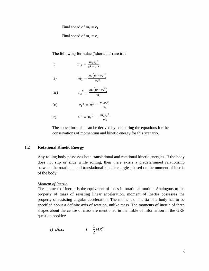
Final speed of m1 = v1
Final speed of m2 = v2
The following formulae (‘shortcuts’) are true:
–
–
The above formulae can be derived by comparing the equations for the
conservations of momentum and kinetic energy for this scenario.
1.2 Rotational Kinetic Energy
Any rolling body possesses both translational and rotational kinetic energies. If the body
does not slip or slide while rolling, then there exists a predetermined relationship
between the rotational and translational kinetic energies, based on the moment of inertia
of the body.
Moment of Inertia
The moment of inertia is the equivalent of mass in rotational motion. Analogous to the
property of mass of resisting linear acceleration, moment of inertia possesses the
property of resisting angular acceleration. The moment of inertia of a body has to be
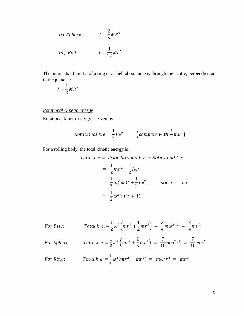
specified about a definite axis of rotation, unlike mass. The moments of inertia of three
shapes about the centre of mass are mentioned in the Table of Information in the GRE
question booklet:
6
The moments of inertia of a ring or a shell about an axis through the centre, perpendicular
to the plane is:
Rotational Kinetic Energy
Rotational kinetic energy is given by:
For a rolling body, the total kinetic energy is:
7
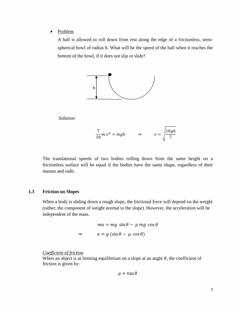
Problem
A ball is allowed to roll down from rest along the edge of a frictionless, semi-
spherical bowl of radius h. What will be the speed of the ball when it reaches the
bottom of the bowl, if it does not slip or slide?
h
Solution:
The translational speeds of two bodies rolling down from the same height on a
frictionless surface will be equal if the bodies have the same shape, regardless of their
masses and radii.
1.3 Friction on Slopes
When a body is sliding down a rough slope, the frictional force will depend on the weight
(rather, the component of weight normal to the slope). However, the acceleration will be
independent of the mass.
Coefficient of friction
When an object is at limiting equilibrium on a slope at an angle , the coefficient of
friction is given by:

8
1.4 Motion under Gravitational Field
Gravitational field is an inverse-square force. For a planet orbiting the sun in a circle, the
following is true:
Some important points to notice here:
i) The motion is independent of the mass of the planet (true for non-circular
orbits too)
ii) The speed (and hence angular speed) is dependent on mass of sun
iii) (Kepler’s third law)
For elliptical orbits, speed of planet is not constant – it is maximum at perigee and
minimum at apogee.
1.5 Lagrangian and Hamiltonian Equations
For each degree of freedom, the equation of motion for it can be obtained by solving the
Hamiltonian or Lagrangian equation.
9
Chapter 2: Thermal Physics
2.1 Boltzmann Distribution
Molecules at any given temperature can occupy different energy levels. As temperature
increases, higher energy levels are occupied with more and more molecules.
T = 0 K, all molecules occupy the lowest energy level existing.
As T → ∞, all the available energy levels are uniformly occupied (after allowing
for degeneracy).
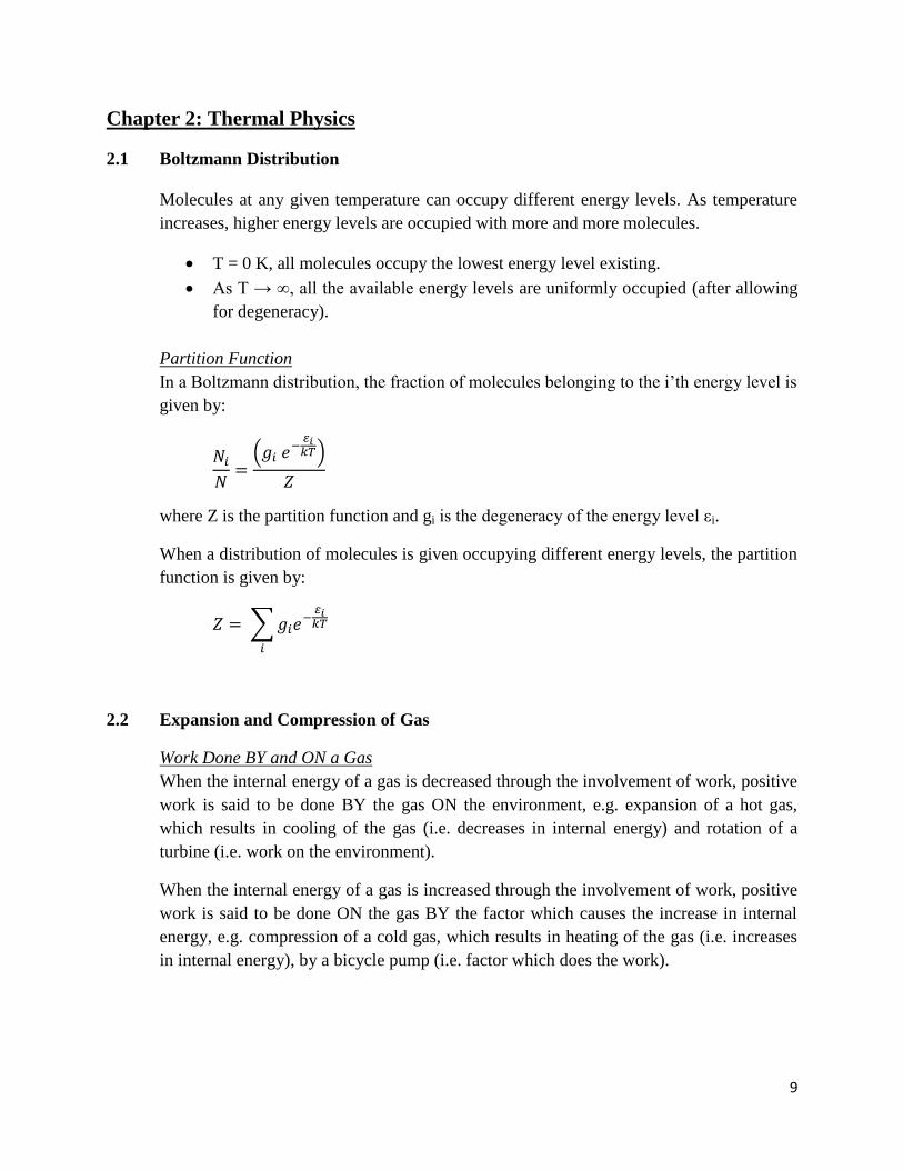
Partition Function
In a Boltzmann distribution, the fraction of molecules belonging to the i’th energy level is
given by:
where Z is the partition function and gi is the degeneracy of the energy level εi.
When a distribution of molecules is given occupying different energy levels, the partition
function is given by:
2.2 Expansion and Compression of Gas
Work Done BY and ON a Gas
When the internal energy of a gas is decreased through the involvement of work, positive
work is said to be done BY the gas ON the environment, e.g. expansion of a hot gas,
which results in cooling of the gas (i.e. decreases in internal energy) and rotation of a
turbine (i.e. work on the environment).
When the internal energy of a gas is increased through the involvement of work, positive
work is said to be done ON the gas BY the factor which causes the increase in internal
energy, e.g. compression of a cold gas, which results in heating of the gas (i.e. increases
in internal energy), by a bicycle pump (i.e. factor which does the work).

10
Work done is given by the formula:
The following pressure-volume diagram illustrates the visual interpretation:
Pressure
W
V1 V2 Volume
For an ideal gas, work done by n moles of gas in an isothermal change is given by:
Some useful shortcuts regarding natural logarithms and work done:
For 0 < x <1, log x is negative (i.e. compression is negative work done by gas)
For x = 1, log x = 0 (i.e. work done is zero if V1 = V2)
For x = 2, log x = 0.69 (i.e. work done is 0.69nRT if volume is doubled)
For x = e, log e = 1 (i.e. work done is 2nRT if volume is expanded 2.71 times)
Work done in an adiabatic change (ΔQ = 0) is always smaller than in an isothermal
change for the same change in temperature.
2.3 Degrees of Freedom
In gases, each degree of freedom contributes
to the . The of the gas is the sum
of the individual contributions of each degree of freedom. Therefore, the of a gas is
the product of the number of degrees of freedom and
.
Area
representing
work done
Upon expanding from V1 to V2:
Work done BY gas =
Work done ON gas =
Vice-versa is true for a compression from V2 to V1

11
Monoatomic Gas
A monoatomic gas is able to move in three directions, and hence possesses three degrees
of freedom.
Diatomic Gas
In addition to the three translational degrees of motion, a diatomic gas at room
temperature is able to rotate on two axes. At higher temperature, the diatomic molecule is
able to rotate on three axes, but the contribution by rotation around the third axis is
negligible.
At even higher temperature, vibration is possible. Vibration adds two degrees of freedom
– one for the translational motion and the other for the potential energy of vibration. This
adds R to .
Consequently, the of a 3D oscillator is 3R.
x
z
y
For a diatomic molecule aligned along the x-axis:
At room temperatures, rotation around the z-axis
and y-axis are permitted.
At higher temperatures, rotation around x-axis is
also possible, but its contribution to Cv is negligible.
12
2.4 Entropy
For a reversible process, entropy change is given by:
For an irreversible process,
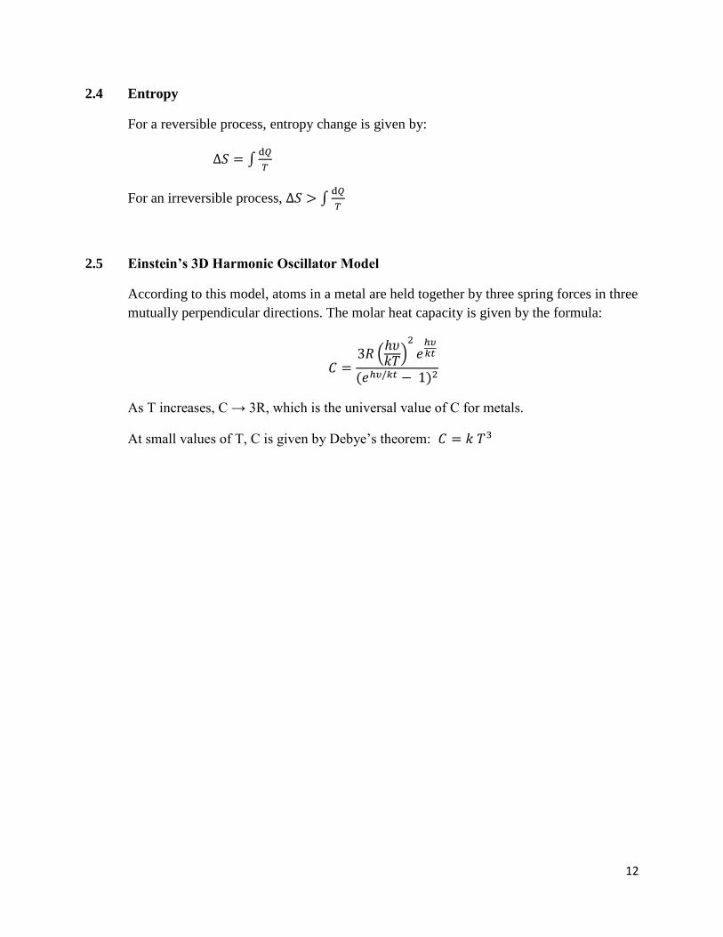
2.5 Einstein’s 3D Harmonic Oscillator Model
According to this model, atoms in a metal are held together by three spring forces in three
mutually perpendicular directions. The molar heat capacity is given by the formula:
As T increases, C → 3R, which is the universal value of C for metals.
At small values of T, C is given by Debye’s theorem:
13
Chapter 3: Modern Physics
3.1 Relativistic Transformation
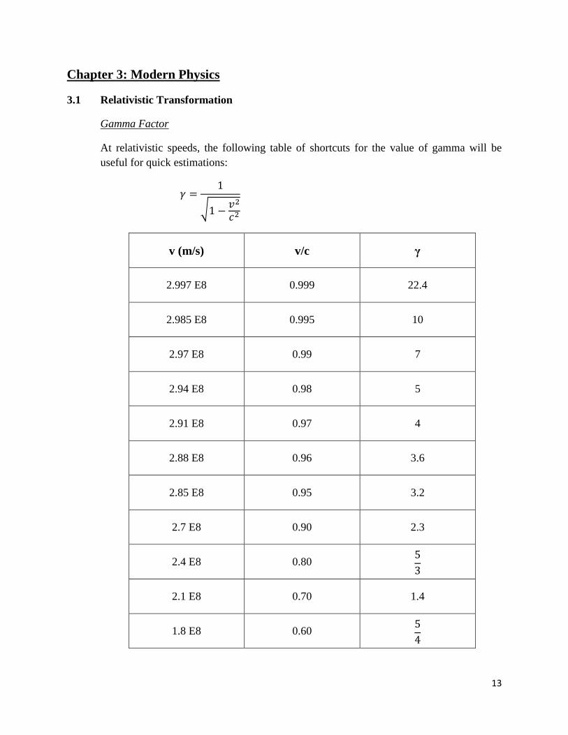
Gamma Factor
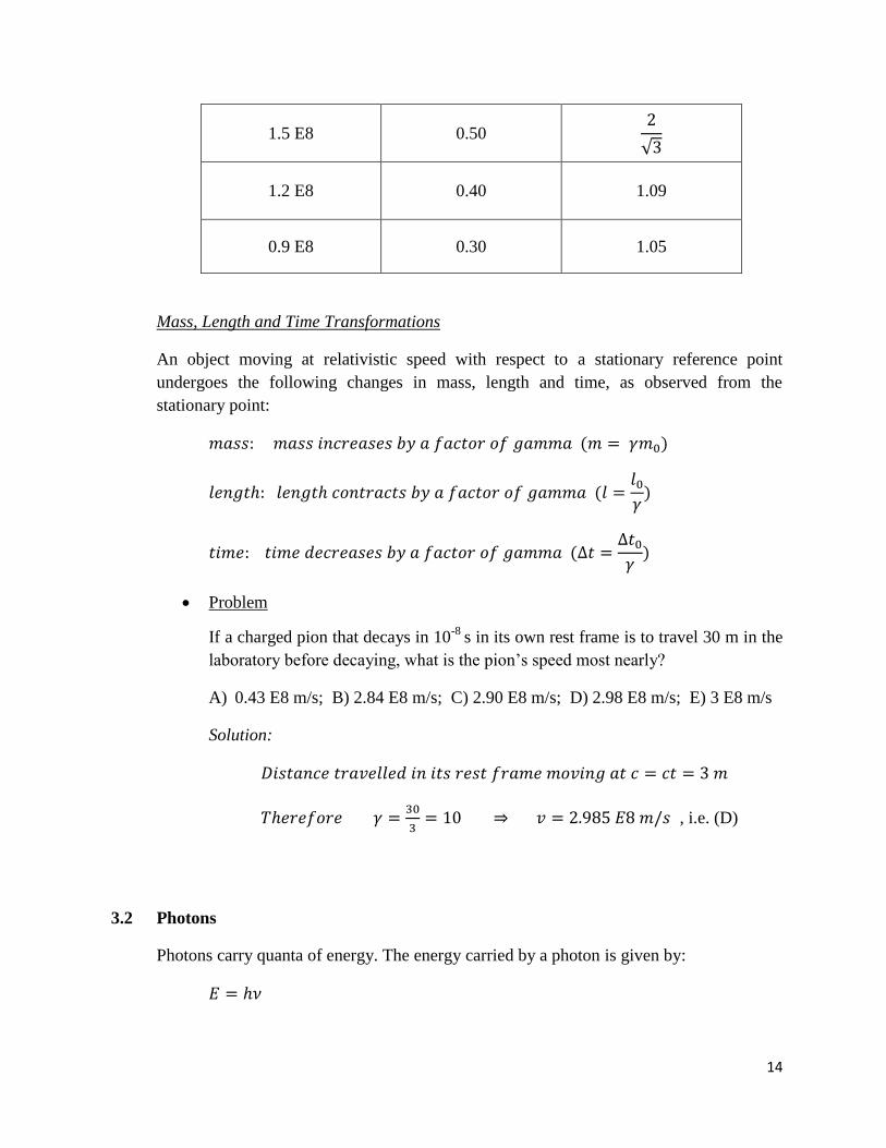
At relativistic speeds, the following table of shortcuts for the value of gamma will be
useful for quick estimations:
v (m/s) v/c γ
2.997 E8 0.999 22.4
2.985 E8 0.995 10
2.97 E8 0.99 7
2.94 E8 0.98 5
2.91 E8 0.97 4
2.88 E8 0.96 3.6
2.85 E8 0.95 3.2
2.7 E8 0.90 2.3
2.4 E8 0.80
2.1 E8 0.70 1.4
1.8 E8 0.60
14
1.5 E8 0.50
1.2 E8 0.40 1.09
0.9 E8 0.30 1.05
Mass, Length and Time Transformations
An object moving at relativistic speed with respect to a stationary reference point
undergoes the following changes in mass, length and time, as observed from the
stationary point:
Problem
If a charged pion that decays in 10-8
s in its own rest frame is to travel 30 m in the
laboratory before decaying, what is the pion’s speed most nearly?
A) 0.43 E8 m/s; B) 2.84 E8 m/s; C) 2.90 E8 m/s; D) 2.98 E8 m/s; E) 3 E8 m/s
Solution:
, i.e. (D)
3.2 Photons
Photons carry quanta of energy. The energy carried by a photon is given by:
15
Photoelectric Effect
In atoms, valence electrons are bound to the atom by a certain amount of energy, called
its work function. When a photon carrying at least that amount of energy strikes the atom,
the electron is ejected.
Compton Effect
When photons are scattered off particles, some of the energy carried by the photons are
absorbed by the particles, while the scattered photons undergo a change in wavelength
given by:
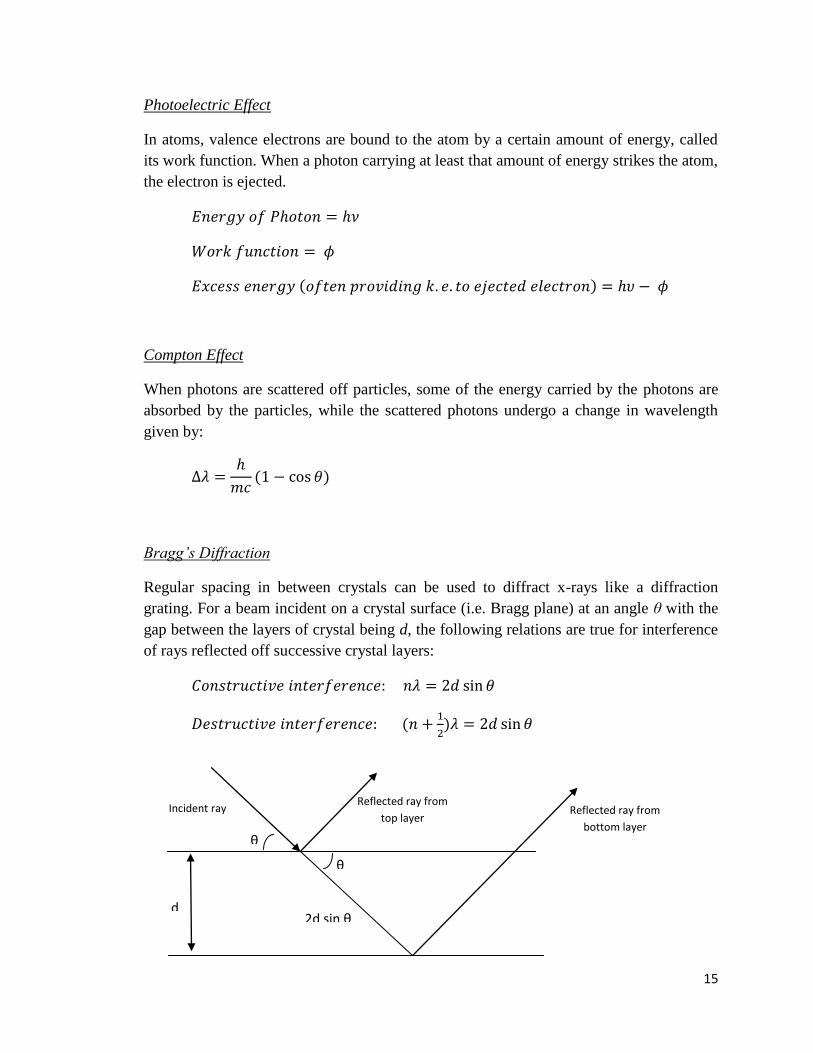
Bragg’s Diffraction
Regular spacing in between crystals can be used to diffract x-rays like a diffraction
grating. For a beam incident on a crystal surface (i.e. Bragg plane) at an angle θ with the
gap between the layers of crystal being d, the following relations are true for interference
of rays reflected off successive crystal layers:
d
Incident ray
Reflected ray from
top layer
Reflected ray from
bottom layer
2d sin θ
θ
θ

16
3.3 Mass-Energy Equivalence
The energy content of mass is given by:
For a mass moving at a relativistic speed, the total energy content of the mass is given by:
De Broglie Wavelength
The De Broglie wavelength is the wavelength of a particle when its wave properties are
considered:
For particles with small momentum, wavelength is large, and vice-versa.
Kinetic energy is given by:
Binding Energy of Nuclei
Nuclei are bound by certain amounts of binding energy dependent on the number of
nucleons. The binding energy per nucleon is greatest for iron-56 isotope (~8.8
MeV/nucleon). During nuclear fission and fusion, the binding energy of the new isotopes
formed increase towards the binding energy of iron-56.
Binding
Energy per
nucleon
Mass Number
Fe-56 (8.8 MeV)

17
3.4 Atomic Absorption and Emission Spectra
When electrons in atomic orbit absorb photons containing certain energy quanta, they
jump to a higher energy level. Similarly, upon transition of electrons from higher to lower
energy levels, photons are emitted. These photons appear as spectral lines when
observed.
Hydrogen-Like Atoms
In hydrogen-like atoms, i.e. atoms containing a single electron, the energies of photons
emitted by transitions of electrons from infinity (i.e. from very far away from the atom)
to any energy level are related by the following formulae:
Important Point: The energy required to remove the second electron is always greater
than the energy required to remove the first electron. As a result, the total energy required
to remove two electrons is more than double the energy required to remove the first
electron.
Special Case 1: Hydrogen Atom
For hydrogen, Z = 1.
For Physics GRE questions, it might be helpful to memorise the above numbers.
18
Also, questions regarding ratios of wavelengths and frequencies of photons can be
answered using the following relations:
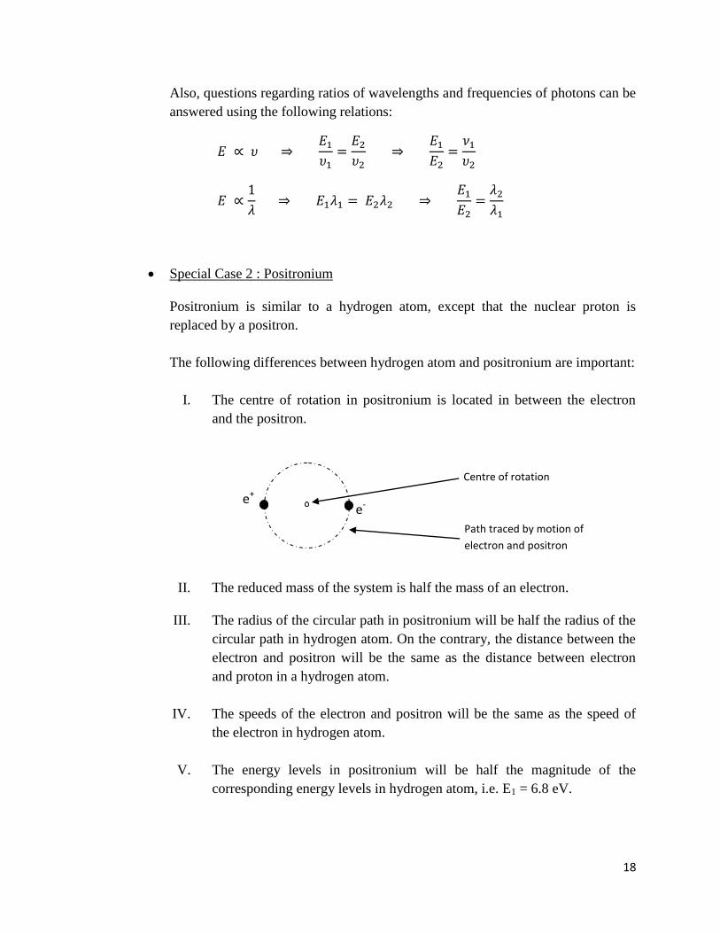
Special Case 2 : Positronium
Positronium is similar to a hydrogen atom, except that the nuclear proton is
replaced by a positron.
The following differences between hydrogen atom and positronium are important:
I. The centre of rotation in positronium is located in between the electron
and the positron.
II. The reduced mass of the system is half the mass of an electron.
III. The radius of the circular path in positronium will be half the radius of the
circular path in hydrogen atom. On the contrary, the distance between the
electron and positron will be the same as the distance between electron
and proton in a hydrogen atom.
IV. The speeds of the electron and positron will be the same as the speed of
the electron in hydrogen atom.
V. The energy levels in positronium will be half the magnitude of the
corresponding energy levels in hydrogen atom, i.e. E1 = 6.8 eV.
e- e+
Path traced by motion of
electron and positron
Centre of rotation
19
3.5 Wien’s Law and Stefan’s Law
Wien’s Law
Of the radiation emitted from a black body, the wavelength emitted with greatest
intensity is inversely proportional to the temperature of the body.
Stefan’s Law
The power per unit area radiated by a black body is directly proportional to the fourth
power of the temperature of the black body.
20
Chapter 4: Electricity and Magnetism
4.1 Circuits
Resistors
Resistors in Series
When connected in series, the total resistance of the combination is the sum of the
individual resistances.
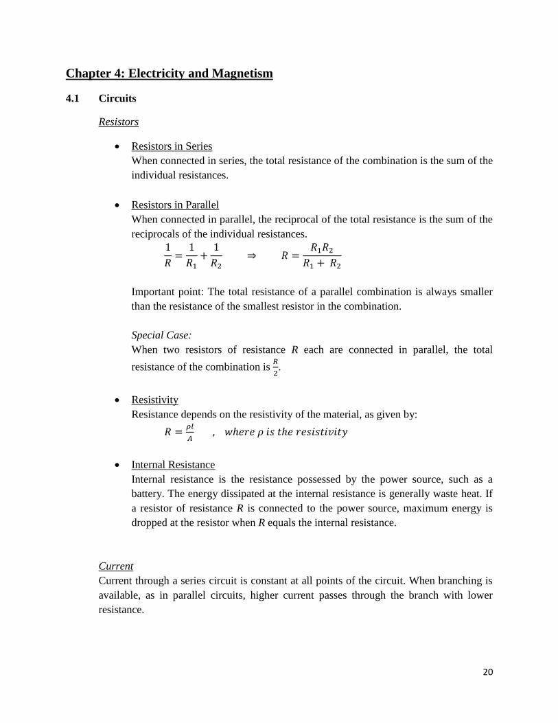
Resistors in Parallel
When connected in parallel, the reciprocal of the total resistance is the sum of the
reciprocals of the individual resistances.
Important point: The total resistance of a parallel combination is always smaller
than the resistance of the smallest resistor in the combination.
Special Case:
When two resistors of resistance R each are connected in parallel, the total
resistance of the combination is
.
Resistivity
Resistance depends on the resistivity of the material, as given by:
Internal Resistance
Internal resistance is the resistance possessed by the power source, such as a
battery. The energy dissipated at the internal resistance is generally waste heat. If
a resistor of resistance R is connected to the power source, maximum energy is
dropped at the resistor when R equals the internal resistance.
Current
Current through a series circuit is constant at all points of the circuit. When branching is
available, as in parallel circuits, higher current passes through the branch with lower
resistance.

21
Speed of charged particles in a current-carrying wire is related by:
The speed of electrons in a metal wire is in the order of cm/s.
Capacitors
Capacitors in Series and Parallel
When connected in series, the total capacitance of the combination is given by a
similar formula as the one for resistors in parallel:
The total capacitance in a series connection is always smaller than the capacitance
of the smallest capacitor.
For capacitors connected in parallel, the total capacitance is given by the sum of
the individual capacitances.
Charges Stored in Capacitors
The charge stored in a capacitor is given by:
For an a.c. voltage, the amount of charge accumulated in a capacitor depends on
the frequency of the voltage. For high frequency, i.e. small time interval between
voltage switching, charge accumulation in capacitor is small, and vice-versa.
The accumulation of charge opposes flow of current through the capacitor, and
hence reduces the rate of accumulation of charge, creating the exponential
relation:
Accordingly, while a capacitor is discharging, the rate of discharging decreases as
charge content decreases.
Voltage Across Capacitors
The voltage across a capacitor increases as it accumulates charge, and vice versa.
22
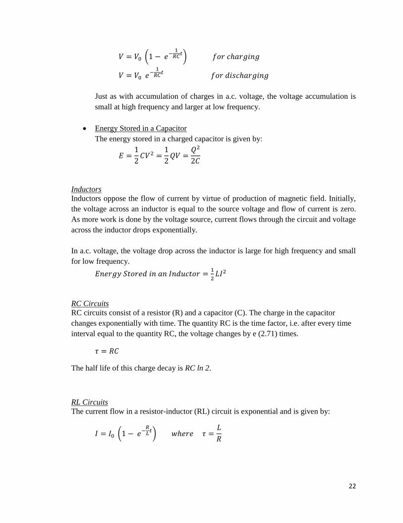
Just as with accumulation of charges in a.c. voltage, the voltage accumulation is
small at high frequency and larger at low frequency.
Energy Stored in a Capacitor
The energy stored in a charged capacitor is given by:
Inductors
Inductors oppose the flow of current by virtue of production of magnetic field. Initially,
the voltage across an inductor is equal to the source voltage and flow of current is zero.
As more work is done by the voltage source, current flows through the circuit and voltage
across the inductor drops exponentially.
In a.c. voltage, the voltage drop across the inductor is large for high frequency and small
for low frequency.
RC Circuits
RC circuits consist of a resistor (R) and a capacitor (C). The charge in the capacitor
changes exponentially with time. The quantity RC is the time factor, i.e. after every time
interval equal to the quantity RC, the voltage changes by e (2.71) times.
The half life of this charge decay is RC ln 2.
RL Circuits
The current flow in a resistor-inductor (RL) circuit is exponential and is given by:
23
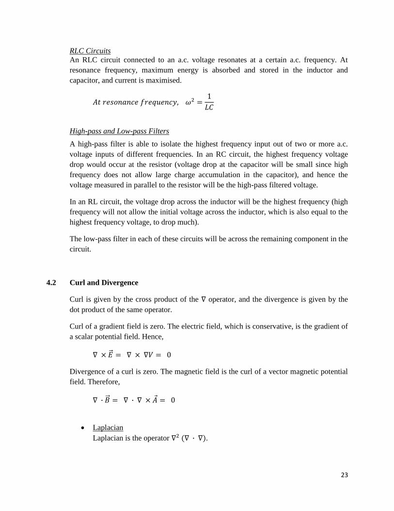
RLC Circuits
An RLC circuit connected to an a.c. voltage resonates at a certain a.c. frequency. At
resonance frequency, maximum energy is absorbed and stored in the inductor and
capacitor, and current is maximised.
High-pass and Low-pass Filters
A high-pass filter is able to isolate the highest frequency input out of two or more a.c.
voltage inputs of different frequencies. In an RC circuit, the highest frequency voltage
drop would occur at the resistor (voltage drop at the capacitor will be small since high
frequency does not allow large charge accumulation in the capacitor), and hence the
voltage measured in parallel to the resistor will be the high-pass filtered voltage.
In an RL circuit, the voltage drop across the inductor will be the highest frequency (high
frequency will not allow the initial voltage across the inductor, which is also equal to the
highest frequency voltage, to drop much).
The low-pass filter in each of these circuits will be across the remaining component in the
circuit.
4.2 Curl and Divergence
Curl is given by the cross product of the operator, and the divergence is given by the
dot product of the same operator.
Curl of a gradient field is zero. The electric field, which is conservative, is the gradient of
a scalar potential field. Hence,
Divergence of a curl is zero. The magnetic field is the curl of a vector magnetic potential
field. Therefore,
Laplacian
Laplacian is the operator .
24
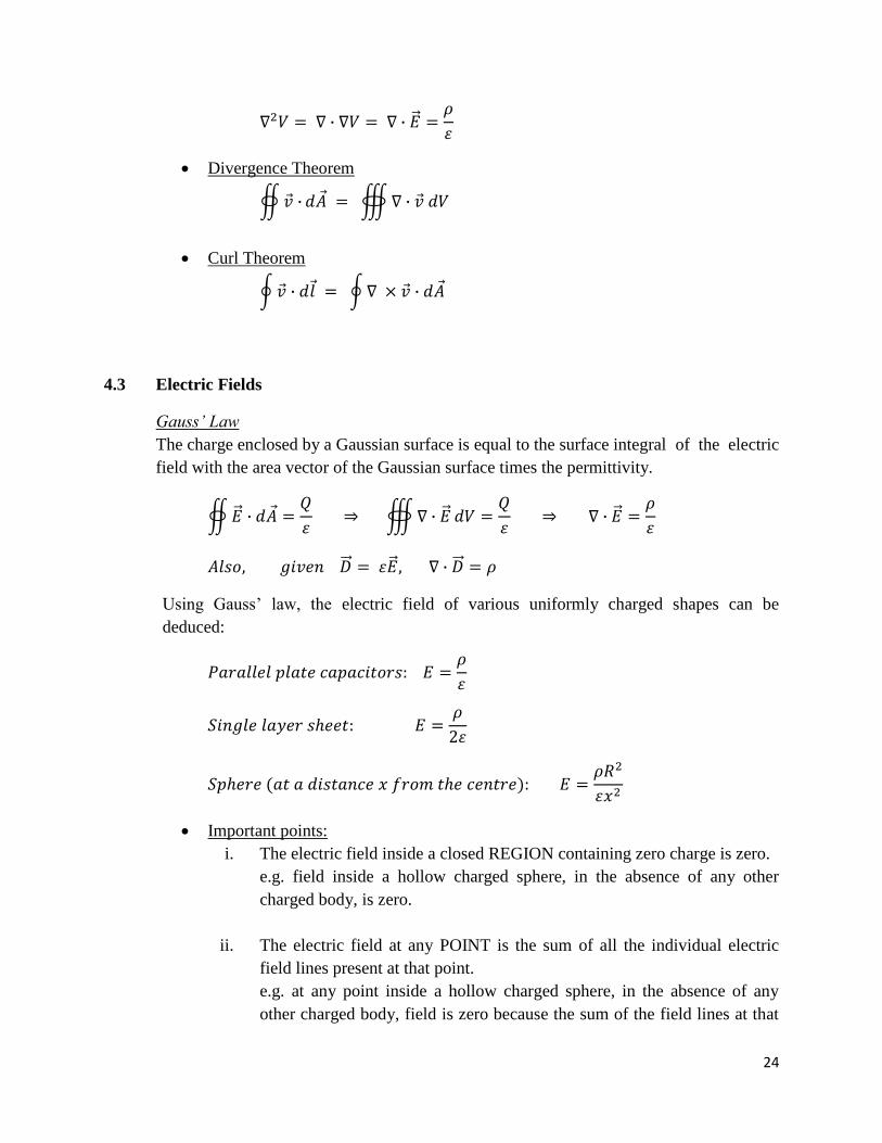
Divergence Theorem
Curl Theorem
4.3 Electric Fields
Gauss’ Law
The charge enclosed by a Gaussian surface is equal to the surface integral of the electric
field with the area vector of the Gaussian surface times the permittivity.
Using Gauss’ law, the electric field of various uniformly charged shapes can be
deduced:
Important points:
i. The electric field inside a closed REGION containing zero charge is zero.
e.g. field inside a hollow charged sphere, in the absence of any other
charged body, is zero.
ii. The electric field at any POINT is the sum of all the individual electric
field lines present at that point.
e.g. at any point inside a hollow charged sphere, in the absence of any
other charged body, field is zero because the sum of the field lines at that
25
point is zero. However, in the presence of an external charged body, the
field at that point will not be zero, but will be equal to the field strength of
the charged body at that point.
iii. Gauss’ law is true only because electric field is an inverse-square field.
Coulomb’s Law
Coulomb’s law gives the force exerted by a point charge on another point charge.
Curl of Electric Field
Since electric field is a conservative field, in the absence of any changing magnetic field,
the closed line integral of an electric field is zero.
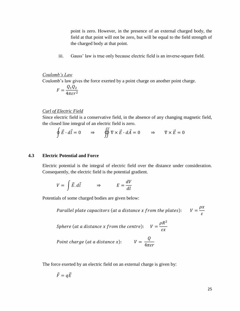
4.3 Electric Potential and Force
Electric potential is the integral of electric field over the distance under consideration.
Consequently, the electric field is the potential gradient.
Potentials of some charged bodies are given below:
The force exerted by an electric field on an external charge is given by:

26
Earnshaw’s Theorem
Earnshaw’s theorem implies that an electrically or magnetically charged particle cannot
be held at equilibrium by the fields of a finite number of other charged particles. The
potential at the location of the particle cannot be a local minimum or maximum, although
it can be a saddle point.
Mirror Charges
The concept of a mirror charge simplifies problems involving a charged body and a
surface at a fixed potential.
e.g. A plane placed at a distance r from a charge q is grounded to maintain a zero
potential. What is the electric field at the midpoint between the charge and the plane?
The situation can be modeled using a mirror charge placed on the other side of the plane
at a distance r, and ignoring the plane altogether. The field at the specified distance is the
sum of the fields of the two charges:
4.4 Magnetic Fields
Right-Hand Grip Rule
For a straight wire carrying a current, the magnetic field is given by the right-hand grip
rule. According to this rule, the wire is gripped with the right-hand with the thumb
pointing in the direction of the current. The direction of the field is given by the direction
of the fingers.
q r r Mirror Charge( –q)
27
Force Between Two Parallel Wires
If two parallel wires carry current in the same direction, then there is attraction between
the wires. If the wires carry current in opposite directions, then there is repulsion.
Biot-Savart Law
The Biot-Savart law gives the magnetic field produced by an electric current.
Curl and Divergence
The divergence of a magnetic field is zero.
This implies that a single point exhibiting properties of a single magnetic pole does not
exist. Magnetic poles must exist in opposite pairs, producing a magnetic field which
starts from the north pole and ends at the south pole. The surface integral of this field
over any closed surface will be zero, since the total number of field lines entering the
surface equals the number of field lines leaving the surface.
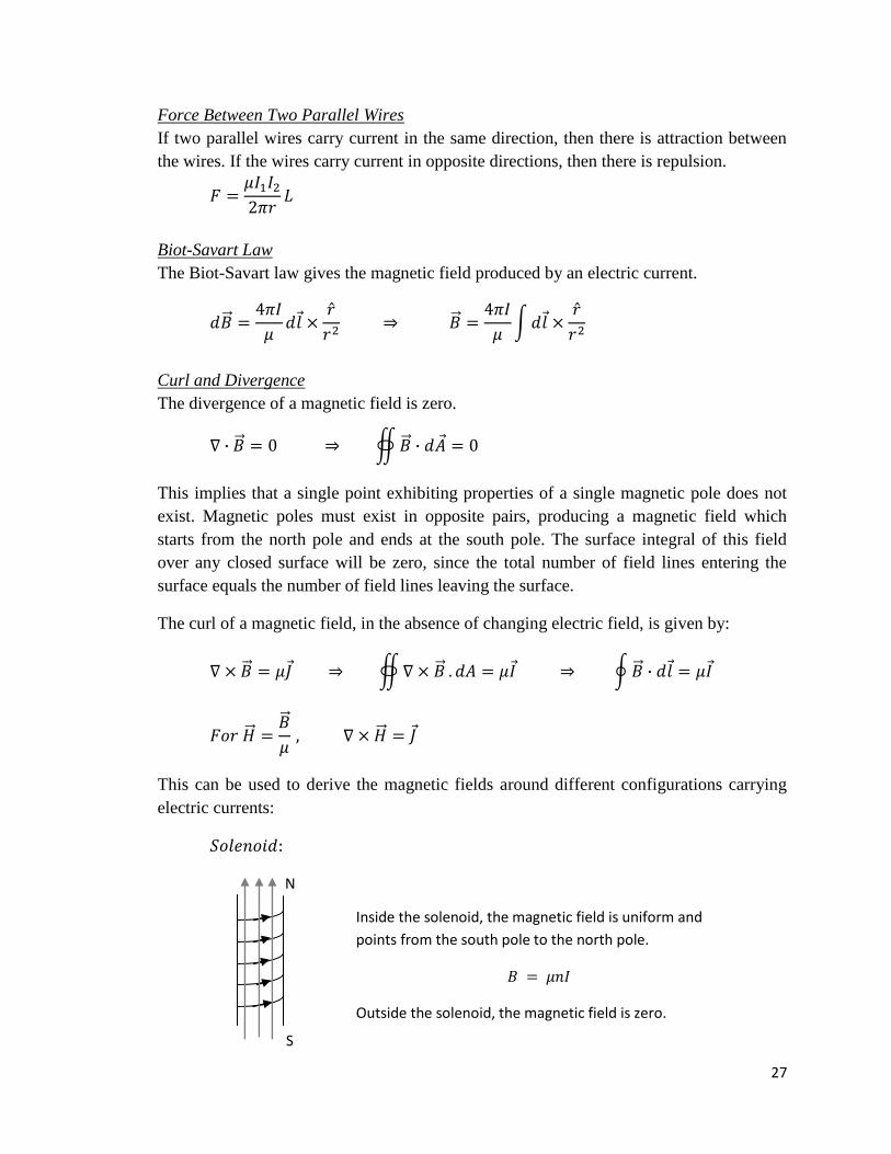
The curl of a magnetic field, in the absence of changing electric field, is given by:
This can be used to derive the magnetic fields around different configurations carrying
electric currents:
N
S
Inside the solenoid, the magnetic field is uniform and
points from the south pole to the north pole.
Outside the solenoid, the magnetic field is zero.
28
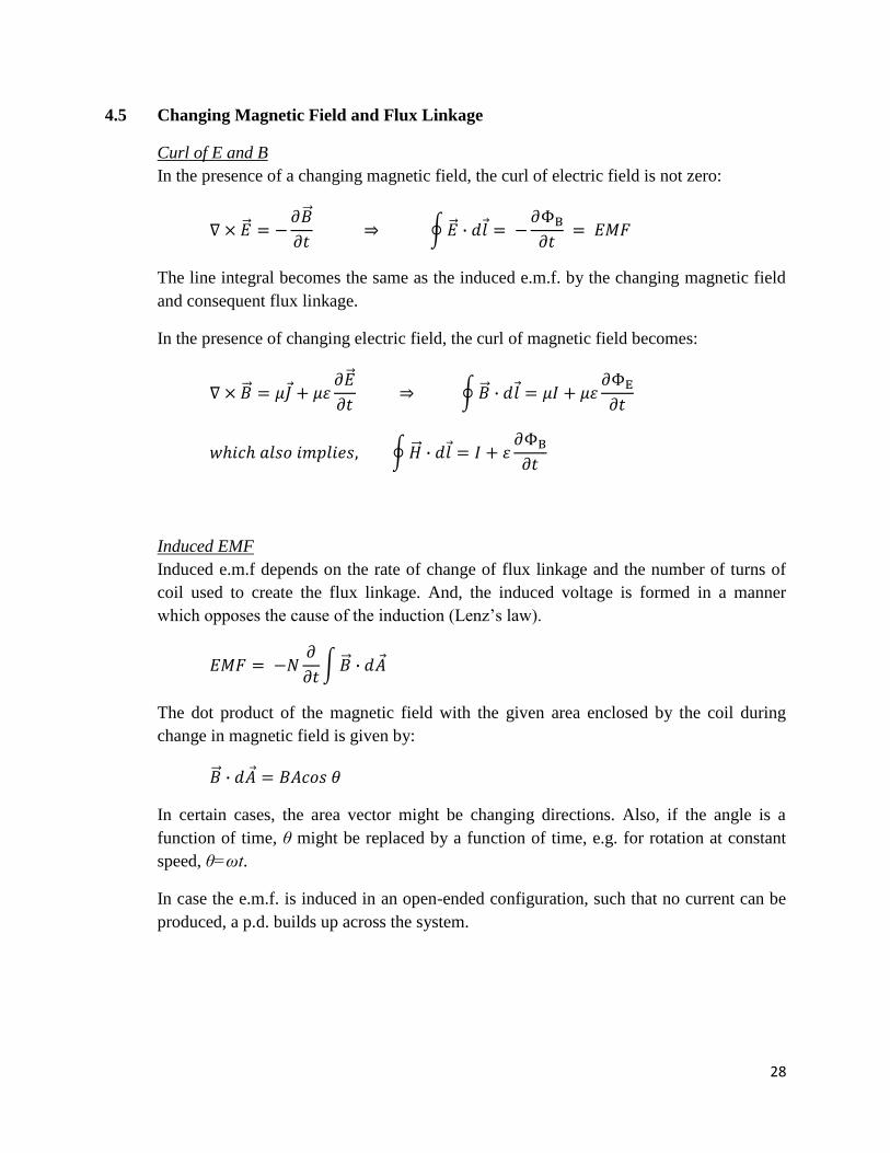
4.5 Changing Magnetic Field and Flux Linkage
Curl of E and B
In the presence of a changing magnetic field, the curl of electric field is not zero:
The line integral becomes the same as the induced e.m.f. by the changing magnetic field
and consequent flux linkage.
In the presence of changing electric field, the curl of magnetic field becomes:
Induced EMF
Induced e.m.f depends on the rate of change of flux linkage and the number of turns of
coil used to create the flux linkage. And, the induced voltage is formed in a manner
which opposes the cause of the induction (Lenz’s law).
The dot product of the magnetic field with the given area enclosed by the coil during
change in magnetic field is given by:
In certain cases, the area vector might be changing directions. Also, if the angle is a
function of time, θ might be replaced by a function of time, e.g. for rotation at constant
speed, θ=ωt.
In case the e.m.f. is induced in an open-ended configuration, such that no current can be
produced, a p.d. builds up across the system.
29
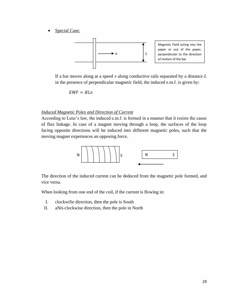
Special Case:
If a bar moves along at a speed v along conductive rails separated by a distance L
in the presence of perpendicular magnetic field, the induced e.m.f. is given by:
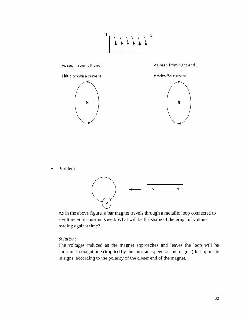
Induced Magnetic Poles and Direction of Current
According to Lenz’s law, the induced e.m.f. is formed in a manner that it resists the cause
of flux linkage. In case of a magnet moving through a loop, the surfaces of the loop
facing opposite directions will be induced into different magnetic poles, such that the
moving magnet experiences an opposing force.
The direction of the induced current can be deduced from the magnetic pole formed, and
vice versa.
When looking from one end of the coil, if the current is flowing in:
I. clockwiSe direction, then the pole is South
II. aNti-clockwise direction, then the pole in North
N S S N
L v
Magnetic Field acting into the
paper or out of the paper,
perpendicular to the direction
of motion of the bar
30
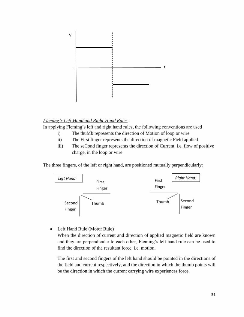
Problem
As in the above figure, a bar magnet travels through a metallic loop connected to
a voltmeter at constant speed. What will be the shape of the graph of voltage
reading against time?
Solution:
The voltages induced as the magnet approaches and leaves the loop will be
constant in magnitude (implied by the constant speed of the magnet) but opposite
in signs, according to the polarity of the closer end of the magnet.
S N
As seen from left end:
aNticlockwise current
curren t
N
S
As seen from right end:
clockwiSe current
S N
V
31
Fleming’s Left-Hand and Right-Hand Rules
In applying Fleming’s left and right hand rules, the following conventions are used
i) The thuMb represents the direction of Motion of loop or wire
ii) The First finger represents the direction of magnetic Field applied
iii) The seCond finger represents the direction of Current, i.e. flow of positive
charge, in the loop or wire
The three fingers, of the left or right hand, are positioned mutually perpendicularly:
Left Hand Rule (Motor Rule)
When the direction of current and direction of applied magnetic field are known
and they are perpendicular to each other, Fleming’s left hand rule can be used to
find the direction of the resultant force, i.e. motion.
The first and second fingers of the left hand should be pointed in the directions of
the field and current respectively, and the direction in which the thumb points will
be the direction in which the current carrying wire experiences force.
V
t
Thumb
First
Finger
Second
Finger
Thumb
First
Finger
Second
Finger
Left Hand: Right Hand:
32
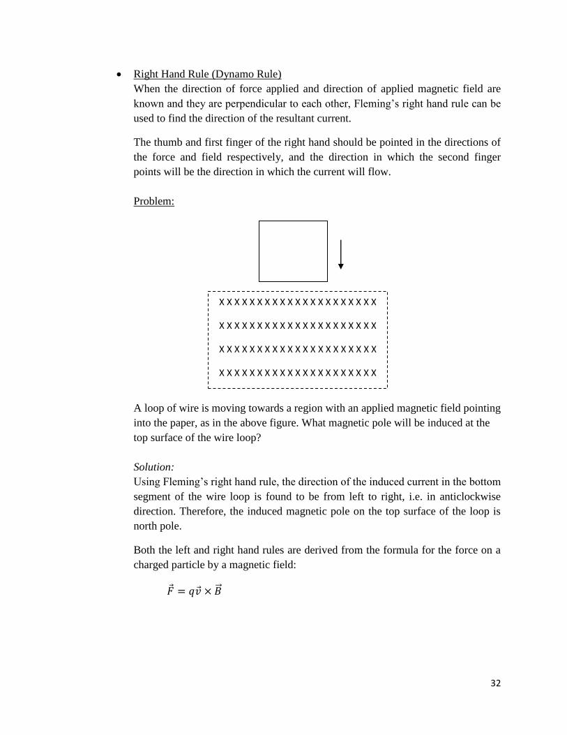
Right Hand Rule (Dynamo Rule)
When the direction of force applied and direction of applied magnetic field are
known and they are perpendicular to each other, Fleming’s right hand rule can be
used to find the direction of the resultant current.
The thumb and first finger of the right hand should be pointed in the directions of
the force and field respectively, and the direction in which the second finger
points will be the direction in which the current will flow.
Problem:
A loop of wire is moving towards a region with an applied magnetic field pointing
into the paper, as in the above figure. What magnetic pole will be induced at the
top surface of the wire loop?
Solution:
Using Fleming’s right hand rule, the direction of the induced current in the bottom
segment of the wire loop is found to be from left to right, i.e. in anticlockwise
direction. Therefore, the induced magnetic pole on the top surface of the loop is
north pole.
Both the left and right hand rules are derived from the formula for the force on a
charged particle by a magnetic field:
X X X X X X X X X X X X X X X X X X X X X
X X X X X X X X X X X X X X X X X X X X X
X X X X X X X X X X X X X X X X X X X X X
X X X X X X X X X X X X X X X X X X X X X
33
4.6 Magnetic Force on Moving Charges
For a charged particle q moving with a velocity in the presence of a magnetic field ,
the force exerted on the charged particle by the magnetic field is given by:
Since current is a flow of charged particles, magnetic force is also exerted on current
carrying wires.
Important Point: The force exerted and the direction of motion is always perpendicular to
the direction of the field. Therefore, the work done by a magnetic field is always zero.
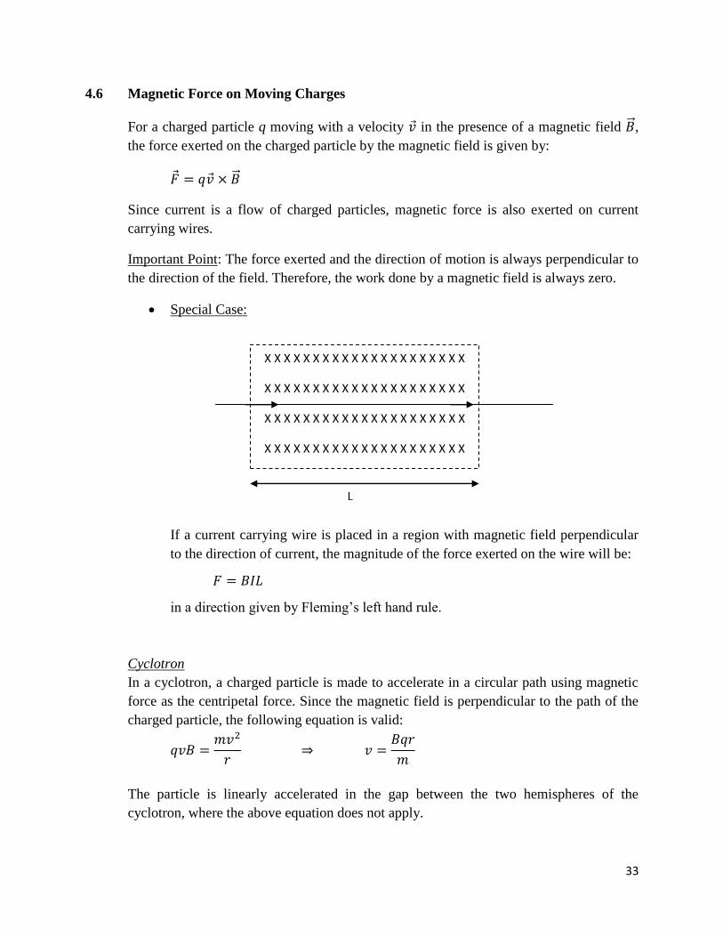
Special Case:
If a current carrying wire is placed in a region with magnetic field perpendicular
to the direction of current, the magnitude of the force exerted on the wire will be:
in a direction given by Fleming’s left hand rule.
Cyclotron
In a cyclotron, a charged particle is made to accelerate in a circular path using magnetic
force as the centripetal force. Since the magnetic field is perpendicular to the path of the
charged particle, the following equation is valid:
The particle is linearly accelerated in the gap between the two hemispheres of the
cyclotron, where the above equation does not apply.
X X X X X X X X X X X X X X X X X X X X X
X X X X X X X X X X X X X X X X X X X X X
X X X X X X X X X X X X X X X X X X X X X
X X X X X X X X X X X X X X X X X X X X X
L

34
Electric and Magnetic Forces Together
When electric and magnetic forces are simultaneously applied on a charged particle, the
resultant force on the particle is:
When the magnetic and electric forces on the charged particle result to zero, the direction
of the electric field must be given by:
Important Point: If the speed of the particle is varied, only the magnetic force changes. If
charge of the particle is varied, magnitudes of both forces are equally affected.
4.7 Electromagnetic Wave
Light is an electromagnetic wave. In the absence of any changing magnetic field or
changing electric field, the electric and magnetic fields satisfy the two wave equations:
It follows that the speed of light in the medium is given by:
Given the direction of propagation of an electromagnetic vector , the directions of the
electric and magnetic field must be oriented such that:
For a plane-polarised wave, the electric and magnetic fields must be constant in direction
and sinusoidal:
The energy density carried by an electromagnetic wave is given by:
35
Chapter 5: Quantum Mechanics
5.1 Wavefunctions
Schrodinger Equation
Locations of particles at quantum energy levels are described using their wavefunctions.
The Schrodinger equation relates the wavefunction of a particle with its energy and
potential applied on it. The time-independent Schrodinger equation, applicable when the
potential is time-independent, is given below:
The solution of the Schrodinger equation gives the shape of the wavefunction under the
given constraints.
Some common wavefunctions, their shapes and energies are listed below:
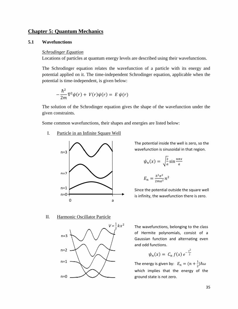
I. Particle in an Infinite Square Well
II. Harmonic Oscillator Particle
Since the potential outside the square well
is infinity, the wavefunction there is zero.
The potential inside the well is zero, so the
wavefunction is sinusoidal in that region.
n=0
n=1
n=2
n=3
V =
The wavefunctions, belonging to the class
of Hermite polynomials, consist of a
Gaussian function and alternating even
and odd functions.
The energy is given by:
which implies that the energy of the
ground state is not zero.
0 a
n=0
n=1
n=2
n=3
36
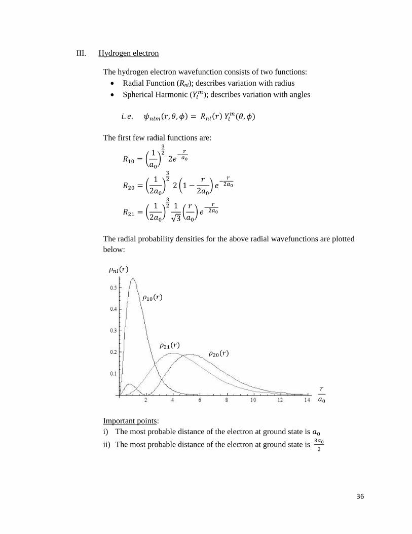
III. Hydrogen electron
The hydrogen electron wavefunction consists of two functions:
Radial Function (Rnl); describes variation with radius
Spherical Harmonic ( ); describes variation with angles
The first few radial functions are:
The radial probability densities for the above radial wavefunctions are plotted
below:
Important points:
i) The most probable distance of the electron at ground state is
ii) The most probable distance of the electron at ground state is

37
Probability of locating a particle in a given region is given by:
For a purely real wavefunction, the complex conjugate of is the same as :
Properties of Wavefunction
A wavefunction must satisfy the following criteria:
i. A wavefunction must be continuous and differentiable everywhere under finite
potential. When travelling from a region of finite potential to a region of infinite
potential, the wavefunction need not be differentiable at the boundaries, though it
still must be continuous, e.g. infinite well boundaries.
ii. The probability of locating the particle over all space (-∞, ∞) must be equal to 1,
i.e. the integral of must be 1. In spherical coordinates, the integral of
must be 1 after inserting an appropriate normalisation constant.
iii. The wavefunction must approach zero as distance increases:
Energy of Wavefunctions
The energy of a wavefunction is the kinetic energy of the particle it represents. A
sinusoidal wavefunction carries positive kinetic energy and an exponential wavefunction
carries negative kinetic energy.
i. The curvature of a sinusoidal wavefunction increases with the kinetic energy.
Higher speed of particle implies higher kinetic energy and greater curvature of its
wavefunction.
ii. Higher speed also indicates lower probability of locating the particle in a given
finite region. This is indicated by the greater curvature of the wavefunction, which
gives a lower value of the integral of .
38
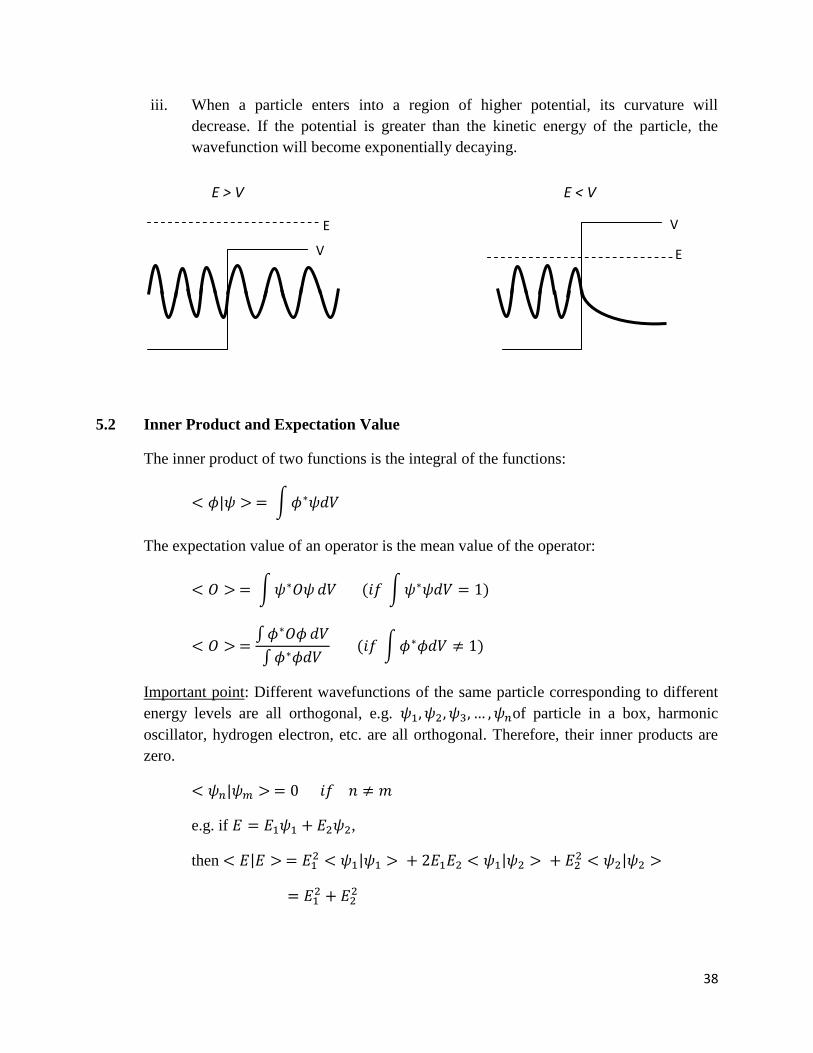
iii. When a particle enters into a region of higher potential, its curvature will
decrease. If the potential is greater than the kinetic energy of the particle, the
wavefunction will become exponentially decaying.
5.2 Inner Product and Expectation Value
The inner product of two functions is the integral of the functions:
The expectation value of an operator is the mean value of the operator:
Important point: Different wavefunctions of the same particle corresponding to different
energy levels are all orthogonal, e.g. of particle in a box, harmonic
oscillator, hydrogen electron, etc. are all orthogonal. Therefore, their inner products are
zero.
e.g. if ,
then
E
V
V
E
E > V E < V
39
Adjoint and Hermitian Operators
If A is an operator, then its adjoint operator (written as A†) satisfies the following
relationship:
Some properties of adjoint operators are listed below:
Matrix Notation
Operators can be represented using matrices. In such a case, the inner product
becomes the matrix product.
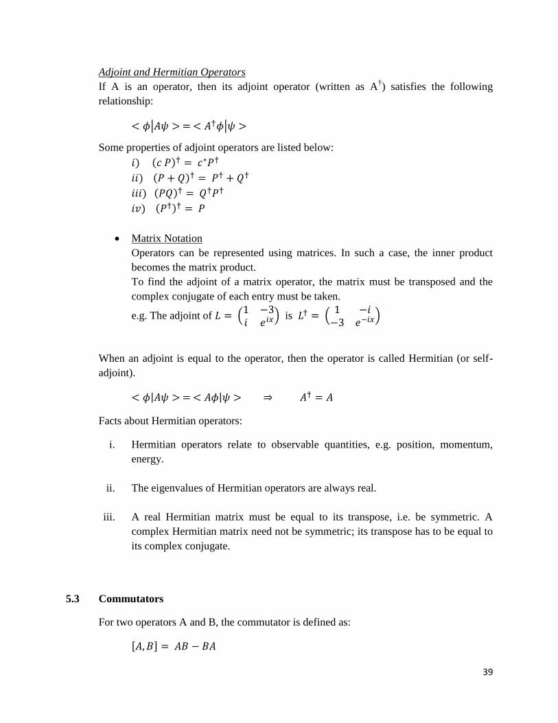
To find the adjoint of a matrix operator, the matrix must be transposed and the
complex conjugate of each entry must be taken.
e.g. The adjoint of
is
When an adjoint is equal to the operator, then the operator is called Hermitian (or self-
adjoint).
Facts about Hermitian operators:
i. Hermitian operators relate to observable quantities, e.g. position, momentum,
energy.
ii. The eigenvalues of Hermitian operators are always real.
iii. A real Hermitian matrix must be equal to its transpose, i.e. be symmetric. A
complex Hermitian matrix need not be symmetric; its transpose has to be equal to
its complex conjugate.
5.3 Commutators
For two operators A and B, the commutator is defined as:
40
When two operators are said to commute with each other, their commutator is zero.
Properties of commutators:
5.4 Quantum Numbers
Pauli’s Exclusion Principle
In an atom, the position of every electron is defined by its unique set to quantum numbers
for that atom. Pauli’s exclusion principle states that no two electrons can have the exact
same four quantum numbers.
Quantum Numbers
The four quantum numbers are:
Principal Quantum Number (n)
It indicates the shell number of the electron, starting from n=1 and increasing.
Angular Momentum Quantum Number (l)
It represents the sub-shell number of the electron. For a shell numbered n, there
are (n+1) sub-shells. It starts from l=0 and goes up to l=n-1. The energy levels at
different sub-shells of the same shell are usually different, although in case of
hydrogen atom they are degenerate.
Magnetic Quantum Number (ml)
It represents the orbital number of the electron. For a sub-shell numbered l, there
are (2l+1) orbitals. It starts from ml=-l and goes up to ml=l, inclusive of ml=0. In
the absence of any strong magnetic field, the orbitals are all degenerate.
Spin Quantum Number (ms)
It represents the spin (intrinsic angular momentum) of the electron. In an orbital,
which can accommodate two electrons, there cannot be more than one electron
with the same spin. It can only have values of
and
, also called
spin-up and spin-down.

41
5.5 Spin
Spin of electrons was discovered through the Stern-Gerlach experiment. When an atom
with a single valence electron is subjected to an inhomogeneous magnetic field, two
distinct fringes are observed, corresponding to the spin-up and spin-down states of the
valence electron.
In matrix notation:
The spin components in the x, y and z directions are represented by the Pauli spin
matrices:
Fermions and Bosons
Particles with half-integer spins (1/2, 3/2, etc.) are called fermions, e.g. electrons,
protons, neutrons.
Particles with integer spins (0, 1, 2, etc.) are called bosons, e.g. photons, pions.
Adding Angular Momenta
Electrons in an atom have both orbital and spin angular momenta. The total angular
momentum is the vector sum of the two momenta:
The value of j ranges from |l-s| to (l+s), changing by 1 for each state.
42
5.6 Stark and Zeeman Effects
Applying an electric field on an atom is analogous to applying a nuclear charge
perturbation. On a hydrogen atom, owing to the electric field, the atom aligns itself to the
direction of the field, i.e. becomes polarized. The change in energy is proportional to the
square of the electric field:
This effect is called the quadratic Stark effect.
For an excited hydrogen atom, the change in energy is proportional to the electric field
(not on its square), and the effect is known as linear Stark effect.
When a magnetic field is applied on a hydrogen atom, the magnetic moments of the
orbital angular momentum and spin angular momentum are affected. This is called the
Zeeman effect. The change in energy is given by:
For the strong-field Zeeman effect, the ml degenerate states separate into different energy
levels (e.g. l = -1, 0, 1) and ms states are added to each different ml state. The resultant
states are the new energy levels.
For weak fields, the different mj states separate into different energy levels.
Selection Rules
Transitions in an atom follow the following selection rules:
5.7 Two Electron Systems
Since electrons are fermions, the wavefunctions of electrons must be anti-symmetric
under particle interchange. Consequently, electrons follow the Pauli’s exclusion
principle, and hence all electrons in an atom cannot drop to the ground state.
43
In an anti-symmetric wavefunction, the sign of the wavefunction must be changed when
the two particles making up the wavefunction are interchanged, e.g.
By interchanging m and n, we get .
Symmetric wavefunctions, such as the wavefunction of a collection of bosons, are
unchanged when particles are interchanged, e.g.
and
which are both unchanged upon interchanging m and n.
Spin Wavefunction
The total wavefunction is made up of the spatial wavefunction and the spin wavefunction.
When both of them are symmetric or anti-symmetric, the total wavefunction is
symmetric. When any one of them is symmetric and the other anti-symmetric, the total
wavefunction is anti-symmetric.
Singlet and Triplet Electron Spin States
A singlet state consists of a single ms value, ms = 0. This occurs when s = 0. In a two-
electron system, it means that the spins of the two electrons must be opposite, such that:
This implies that a singlet state has anti-symmetric spin wavefunction, and hence
symmetric spatial wavefunction.
In a triplet state, ms = -1, 0, 1. This occurs for s = 1, and is brought about by two
electrons with same spins:
The triplet state has symmetric spin wavefunction and hence anti-symmetric spatial
wavefunction.
44
Chapter 6: Optics
6.1 Concave Lenses
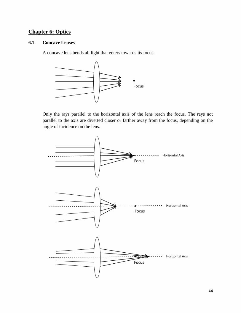
A concave lens bends all light that enters towards its focus.
Only the rays parallel to the horizontal axis of the lens reach the focus. The rays not
parallel to the axis are diverted closer or farther away from the focus, depending on the
angle of incidence on the lens.
Focus
Focus
Horizontal Axis
Focus
Horizontal Axis
Focus
Horizontal Axis

45
Some properties about images formed by concave lenses:
For parallel rays, i.e. rays coming from an object at infinity, the image is real and
formed at the focus.
For an object located at a distance greater than 2f (f is the focal length), the image
is real and formed between f and 2f on the other side.
For an object located at 2f, the image is real and formed at 2f.
For an object located between f and 2f, the image is real and formed at a distance
greater 2f.
For an object located at f, the image is formed at infinity.
For an object located at a distance below f, the image is virtual and observed at f.
The following table summarises the points:
Note: For a single lens arrangement, any real image formed must be located beyond f. For
more than one lens, the image formed may be located at a distance smaller than f.
All real images formed are inverted but the virtual image observed is not inverted.
Magnification
For a single lens, magnification is given by the ratio of the image height to object height,
or by the ratio of the image distance to object distance.
Important Point: If a lens is broken into a smaller piece, the properties of the image
formed remain unchanged except for the brightness. The brightness of the image
decreases since fewer rays of light can enter the lens.
Horizontal
Axis
∞
f 2f
At f
Between f
and 2f Beyond 2f
At 2f At ∞
Virtual Image
observed at f
46
Resolution
In astronomical telescopes, the resolution of the lens allows the viewer to distinguish
between objects with a minimum angular difference between them. This angle is related
to the diameter of the lens and wavelength of light using the formula:
6.2 Pin-Hole Camera
A pin-hole camera uses light entering through a pin-hole to produce an image inside a
dark enclosure. For a certain diameter of the pin-hole, the image formed has the
minimum blur, owing to minimised diffraction at the smallest possible pin-hole diameter.
This diameter is given by:
6.3 Single Slit and Double Slit Interference
When coherent light is projected through a single aperture, the resultant pattern observed
on a screen is described by the following formulae:
When using double slits, the pattern is described by:
For multiple slits, such as a diffraction grating, the equation is:
For light incident at an angle , on a diffraction grating, it follows:
47
6.4 Reflection at Thin Surfaces
When light is reflected and refracted at a surface, the following are true:
If the refractive index of the surface is greater than the refractive index of the
medium through which the incident light propagated, then the phase of the
reflected light will be inverted. If not, then the phase of the reflected light remains
unchanged.
The phase of the refracted light remains unaltered, regardless of the refractive
indices.
The speed and wavelength of the refracted wave changes according to refractive
index, whereas the frequency remains constant. For transition from region of low
to high refractive index, both speed and wavelength decrease, and vice-versa.
When light is incident on a thin surface and reflected off both the top and bottom
surfaces, the reflected waves off both surfaces may interfere constructively or
destructively, depending on the relative refractive indices, surface width and wavelength
of the incident light.
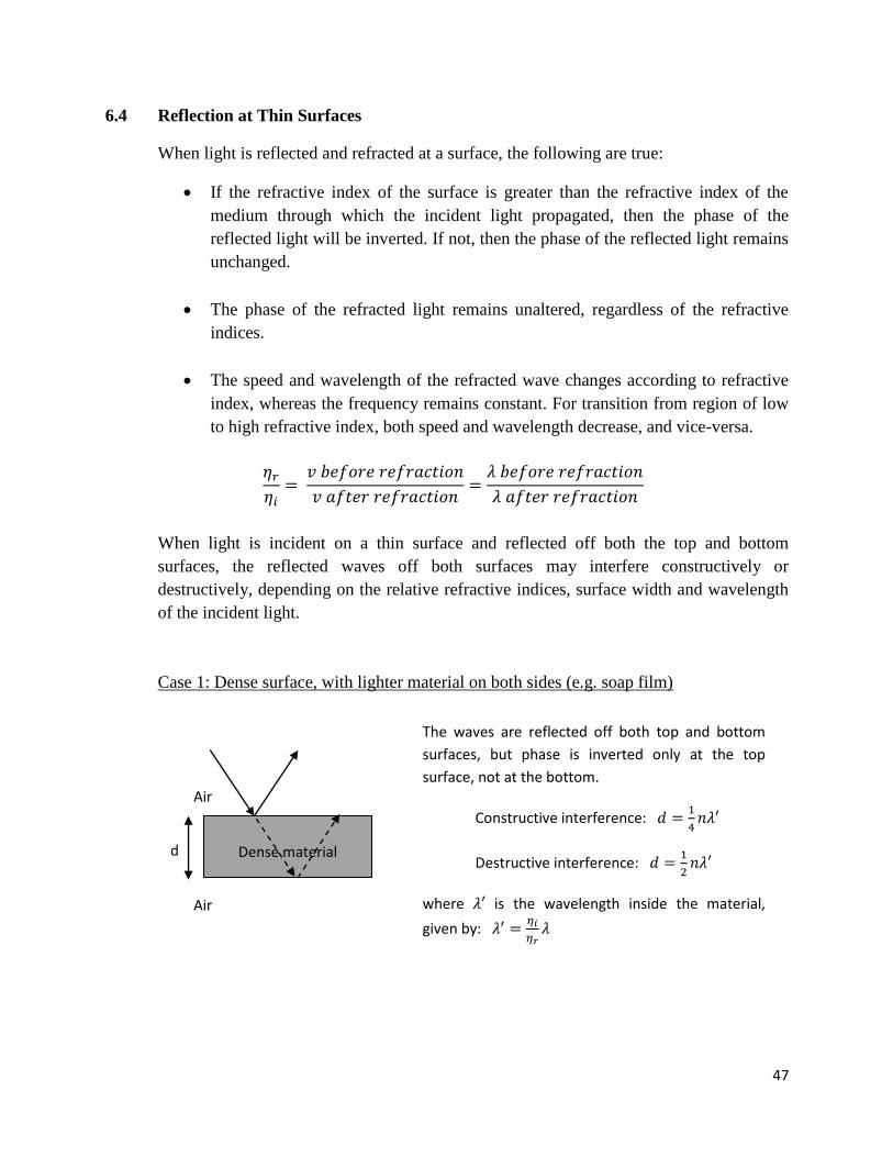
Case 1: Dense surface, with lighter material on both sides (e.g. soap film)
Dense material
Air
Air
The waves are reflected off both top and bottom
surfaces, but phase is inverted only at the top
surface, not at the bottom.
Constructive interference:
Destructive interference:
where is the wavelength inside the material,
given by:
d

48
Case 2: Dense surface, with denser material below (e.g. oil on glass)
6.5 Polarised Light
A beam of light may contain waves oriented in different directions, all of which are
perpendicular to the direction of propagation. By polarising, waves of a particular
orientation only can be filtered out. Polarisation can be carried out using a polariser,
which produces plane-polarised light.
When plane-polarised light is filtered through a polariser at an angle θ, the following
changes occur:
The orientation of the filtered light is rotated by an angle θ.
intensity of the filtered light is given by:
For plane-polarised light passing through two polarisers placed at 450 to each other and
the second lens being perpendicular to the direction of polarisation of the light, the
intensity of the light emerging at the end is a quarter of the original intensity.
Dense material
Air
d
Denser material
The waves are reflected off both top and bottom
surfaces, and phase is inverted upon reflection at
each surface.
Constructive interference:
Destructive interference:
where is the wavelength inside the material,
given by: