· PREFA CE This laboratory manual has been designed primarily for use in the author’s classes...
161
Transcript of · PREFA CE This laboratory manual has been designed primarily for use in the author’s classes...


LA BORA TORY COURSE
IN
ELECTROCHEMISTRY


LA BORA TORY COURSE
ELECTROCHEMISTRY
BY
OLIVER P . WATTS , PH. D .
A S S ISTA NT PR OFES SOR OF A PPLIED ELECTR OCHEM ISTBY
THE UNIV ER S ITY OF W ISCONS IN
FIR ST EDITION
McGR A W —HILL BOOK COMPANY,INC .
239 WEST 3QTR STREET ,NEW YORK
6 BOUVERIE STREET , LONDON, E . C .
1 9 1 4

COPYR IGHT , 1914, BY THE
MCGRA W - HILL BOOK COMPANY , INC .
T H E . M A P L E . P R E S S . Y O B K O P A

PREFA CE
This laboratory manual has been designed primarily
for use in the author ’s classes in the Univ ersity of Wisconsin , and embodies the notes originally prepared byC . F . Burg ess, former head of the Chemical Engineeringdepartment of the University
,together with many new
experiments and much additional material . It is hopedthat it may prove a useful handbook in applied electrochemical courses elsewhere than at Wisconsin .
Thanks are due to Mr . C . F . Burgess for the use of hisnotes
,and to Mr . Claude N . Hitchcock for the drawings
which illustrate the text,and for the use of figures 13 ,
14 and 15 , which were orig inally published in his paperupon Polarization Single Potentials (vol . 25, Transactionsof Americal Electrochemical Society) .
0 . P . W .
Sept , 1914.
23 4 6 80


CONTENTS
PA GEINTR ODUCTION
LABOR ATORY EQ UIPMENT .
INSTR UCTIONS FOR STUDENTS
Q UA LITATIVE EXPER IMENTS ON ELECTR OLYSISSPECIFIC R ESISTANCE .
POLA R I Z A TIONFA R ADAY’S LA W
POTENTIA L AND ELECTR OMOTIVE FOR CE
DISCHA R GE POTENTIA LSOVERVOLTA GEPA SSIVE STATECOR R OS ION OF META LSELECTR OLYTIC SEPA R A TION OF META LSELECTR OLYTIC ANA LYS IS .
INTERMEDIA TE ELECTR ODES .
ELECTR OPLA TING BA THs .
SOLUTIONS FOR COLOR ING A ND OXIDI Z ING META LS .
PR INCIPLES OF ELECTR ODEPOS ITIONCLEANING AND POLISHINGNICKEL PLA TINGCOPPER PLATINGTHE DEPOS ITION OF ALLOYSBR A SS PLATINGSILVER PLA TINGEXPER IMENTS IN PLA TINGOXIDATION AND R EDUCTION .
OTHER ELECTR OLYTIC PR EPA R A TIONSAPPENDIXINDEX


A LA BORA TORY COUR SE IN
ELECTROCHEMISTRY
INTRODUCTION
The experiments in this manual have been chosen toillustrate the general principles which underlie the moreimportant applications of electrochemistry . No attempthas been made to adapt commercial processes
'
to thelaboratory
,although a few experiments Of this character
,
in which the apparatus lends itself readily to laboratoryuse
,have been included . The electric furnace and
batteries have been omitted , since they are studied asseparate courses by the author ’s classes . Electrolyticanalysis has been developed to such an extent that it nowconstitutes a study by itself
,and cannot be adequately
treated in a book on electrochemistry in general . A l
though a few simple experiments are given , the studentwho wishes to study this branch of electrochemistry isreferred to the well-known texts by Smith and Classen .
Even with the above limitations in scope,it will
probably be impossible for the student to perform allof the experiments in the time available . It will befound
,however
,that under many topics the experiments
are so similar in nature that the method of operation andthe use of the apparatus may be learned from any one ofthem . It is therefore suggested that in such cases theclass or laboratory section work together on the topic , aparticular experiment being assigned to one or two students who report their data and conclusions to the classfor discussion . All data and results may be recorded in

2 A LAB ORATORY COURSE IN ELECTROCHEMISTRY
the notebooks, but credited to the observer, so that eachstudent will have a record of the experiments of others aswell as of his own.
The laboratory work should be accompanied by lectures
,recitations and assigned reading in books and per
iodicals. The latter is valuable,not only for the infor
mation gained,but quite as much for the acquaintance
obtained with electrochemical literature and the men whoare producing it .
Laboratory Equipment
A brief description of the laboratory equipment whichis provided for these experiments may be useful .The laboratory receives current over three pairs of
cables , two from the main switch-board,and one running
directly from the storage battery in the basement . Theadvantage of this direct connection of the battery is thatexperiments cannot be interrupted by the accidentalpulling of the wrong plug from the switch- board . Thetwo pairs of cables from the switch-board are usuallyconnected to 1 10 volts direct and alternating pressurerespectively . From the cables wires are brought downto terminals above and at the back of each student ’splace at the laboratory desk . The 1 10- volt direct current can be used only during the day,
but the 10-voltbattery and alternating pressures are always available .
The battery current is used in the majority of experiments , while the alternating current is useful for drivingmotors and heating electrolytes in experiments that arecontinued over night .The storage battery consists of nine sets connected in
parallel, each set having five 160 ampere- hour cells inseries, making the total capacity 1440 ampere-hours .By means of switches
,any number of sets is readily

A LABORATORY COURSE IN ELECTROCHEMISTRY 3
connected in series for charging . A 6-volt battery ofhalf this capacity would probably prove ample for ordi
nary demands .There is available to each student direct current at 10
and 1 10 volts pressure . Control of either current oras may be required for any particular experi
ment,is secured by portable rheostats
,consisting of small
lamp banks,and the ordinary wire-wound rheostats with
sliding contacts . About a third of the wire rheostatshave resistances high enough to permit their use on the
1 10-volt circuit .A second pair of cables from the battery would be an
advantage,as one pair could then be reserved for experi
ments requiring constancy of line voltage, thus avoidingthe fluctuations produced by the use of the electriccleaner and similar intermittent high- current work.
Ammeters,voltmeters
,rheostats
,etc .
,are kept in
casesin the laboratory, from which they are taken by thestudents at the beginning of the four- hour laboratoryperiod
,and returned at its close . Lamp cord, cut to
difierent lengths , with an inch of bare No . 18 copper wiresoldered to the ends
,is used for electrical connections .
This method of distribution and control of current isrecommended for its simplicity and economy, and forthe practice which it gives the student in setting upelectrical circuits and in the control of the electriccurrent . The last feature is especially important .Ammeters having ranges of 1 and of 10 amperes are
most used,although at least one instrument of 50
amperes capacity should be available . Two or threedouble- scale milliammeters (range 50 and 500) areneeded . Although double- scale voltmeters are not soconvenient for rapid reading as single- scale instruments
,a
considerable saving in cost can be effected by their usefor a large part of the voltmeter equipment . The two


LA BORA TORY COURSE
IN
ELECTROCHEMISTRY

6 A LAB ORATORY COURSE IN ELECTROCHEMISTRY
tion, and as a study of the process of electrolysis ; therefore anything new , or of interest to the student shouldbe recorded . To learn how to set up apparatus and tocontrol the electric current for various purposes is also avaluable part of laboratory practice .
Every electric circuit should contain a switch,in order
that the circuit may be broken promptly in case of accident, and a rheostat suited to the voltage employed .
Knowing the line voltage and the current desired,the
resistance required for the rheostat may be calculated
from the equation representing Ohm ’s Law : R in
which E is the in volts , I is the current inamperes,and R is the resistance in ohms . In connecting a rheostat
,great care should be taken to see that at
the outset it is adjusted for its maximum resistance .
Carelessness in this respect may result in the inj ury,
or even in the destruction of the electrical Instruments .Students are expected to report at once any damage
to instruments,and are held responsible for repairs .
The polarity of all cable terminals in the laboratoryshould be plainly marked , and at least one terminal ofevery ammeter and voltmeter has been marked by themaker . Ammeters should be connected in series , i .a.
,
so that the full current flowing in the circuit must passthrough the instrument . Unless otherwise specificallystated
,voltmeters should be connected across the two
points whose difference of potential it is desired to measure . The positive terminal of the ammeter should beconnected to the wire which has come from the positiveterminal of the line
,and the positive of the voltmeter
shou ldfgo to the anode , i .e.,to the side of the electrolytic
cell which is connected to the positive of the line .
Before closing the switch,the student should trace out
the circuit carefully, to see that the current will go only

A LAB ORATORY COURSE IN ELECTROCHEMISTRY 7
where desired,and that the instruments are connected so
that the current will enter at their positive terminals .
This is best done by starting at the positive terminal ofthe line and following the circuit by actual physical contact of the hand , through the cell and instruments,around to the negative terminal of the line . For takingdown the apparatus there is but one safe rule to follow :after opening the switch , first disconnect both wires from
the line termina ls . This insures that no live wires are onthe desk top
,and all danger of a short- circuit is avoided .
In order to use electrical instruments intelligently andsafely
,it is necessary to understand their construction .
The principles of operation of the Weston direct- currentinstruments will be described .
The millivoltmeter is the basis of both the voltmeterand the ammeter . Examination shows that the millivoltmeter consists of a movable coil of very fine wire, towhich the needle is attached, carefully pivoted on j ewelled be‘arings between the poles of a permanent magnet .Current enters and leaves the coil through very fine steelsprings
,one of which is visible at the upper bearing .
When current passes through the coil,it sets up a mag
netic field,which
,reacting with the field of the permanent
magnet, turns the coil and moves the needle up the scale .
When the current ceases,the springs return the needle to
zero . The delicacy of the springs and coil indicate thatonly extremely small currents can be sent through a millivoltmeter without injuring it .The voltmeter consists of a millivoltmeter with aresistance placed in series with the movable coil . Thescale is marked in volts, and the resistance is made suchthat full- scale deflection is obtained when the voltagefor which the instrument is designed is impressed acrossits terminals . Compare the resistance of a millivoltmeter with the resistances oi several voltmeters of differ
2

8 A LABORATORY COURSE IN ELECTROCHEMISTRY
ent ranges . Compute the current which flows througheach instrument at full- scale deflection . In the doublescale voltmeter
,the series resistance is divided into two
portions,and a third binding post is placed between the
resistance coils . What must be the relation between thetotal resistances of the instrument when using the upperand the lower scales
,if one scale is twice the other ?
Fifty times ? Verify your prediction by looking up theresistances marked on laboratory instruments .
The ammeter is made up of a millivoltmeter, and acarefully made resistance called a shunt . The currentto be measured is sent through the shunt , and the millivoltmeter is connected so that it reads the fall of potentialproduced in the shunt by the current . The scale isusually marked directly in amperes . For currents lessthan 100 amperes
,the shunt is often concealed within the
case of the instrument,but for very large currents, it is
always separate from the millivoltmeter, and is thencalled an external shunt . It is evident that
,by the use of
a second shunt having a different resistance , the range ofthe instrument may be greatly altered .
Danger"The millivoltmeter, usually marked ammeter
,designed for use with an external shunt , must never
be directly connected to the electrical circuit .
Voltmeters may be protected from injury by takingcare to connect them to the circuit so that the deflectionof the needle is in the proper direction
,and by never
connecting them to a source of pressure greater than thescale reading . When in doubt whether a circuit is ofhigh or low pressure
,use a high reading instrument .
Ammeters should be protected by a rheostat of suchresistance that the current will be within the range of theammeter. Fuses may of course be used
,but they are
not necessary for careful students .The number and range of voltmeters and ammeters

10 A LAB ORATORY COURSE IN ELECTROCHEMISTR Y
mance requires constant attention and keen use of theeyes to Observe all that happens . Phenomena demanding attention are the solubility or insolubil ity of anodes
,
the evolution of gas at either or both electrodes , whatclasses of substances are liberated at the anode and whatat the cathode
,and the effect of low and of high- current
densities to 5 amperes per sq . dm . ) The questionswith each experiment are intended as suggestions
,not as
limitations to observation by the student . Litmus paper
will prove useful in detecting changes which might otherwise be overlooked . The reactions occurring at the electrodes or in the electrolyte may be expressed most brieflyby chemical equations .
EXPERIMENT 1
TR F EFFECT OF DIFFERENT ELECTRODES UPON THEPROCESS OF ELECTROLYSIS
Using about an eight percent solution of copper sulphate
,connect three cells in series .
CATHODE
carboncarbonlead
Pass a current of about amperes per sq . dm . andobserve the effect upon the electrodes and the electrolyte .
Increase the current to three or four times its initialvalue, and after five minutes again observe the effects .
What electrodes are insoluble in this electrolyte ? Whatis the gas ?S imilarly use dilute sulphuric acid as electrolyte .
ANODE CATHODEd . lead leade. copper lead

A LABORATORY COURSE IN ELECTROCHEMISTRY 1 1
EXPERIMENT 2
REACTIONS BETWEEN ELECTRODE PRODUCTS
Pass current through three cells in series .
ANODE CATHODE ELECTROLYTEa . lead lead NaN0 3 15 percentb. iron iron NaN0 3 15 percentc. iron iron NaC l 15 percent
What anodes are insoluble ? Explain the formation ofprecipitates . Why the different results in b and c?
What are the gases ? How do you explain the surprising
phenomenon which occurs in b at low- current densities ?C an current pas s without equivalent chemical change?
EXPERIMENT 3
ELECTROLYTIC REDUCTION
Use a lead anode, and a cathode of galena (PbS) indilute sulphuric acid . What chemical changes occur?
EXPERIMENT 4
ELECTROLYSIS OF POTASSIUM BROMIDE
Use an anode of platinum wire,and a cathode of copper
in a ten percent solution of potassium bromide . Placethe electrodes far apart
,and test with litmus paper
between as well as at the electrodes . Use a very smallcurrent at first . Increase this until there is a change inthe action occurring at the anode . Such liberation of
gas at anode or cathode may usually be brought about bythe use of extremely high- current densities . How do youexplain it?

12 A LABORATORY COURSE IN ELECTROCHEMISTRY
EXPERIMENT 5
THE EFFECT OF THE CATHODE MATERIAL UPONELECTROLYSIS
Electrolyze a ten percent solution of salt, using a verysmall ampere) current for the first three minutes
,
and the two cells in series .
a . With carbon electrodes .
b. With a carbon anode and a mercury cathode .
Pour a thin layer of mercury into the electrolytic cell andmake contact with it by means of an insulated wire .
What difference is noted in the two cells on startingelectrolysis ? Is it a case of the passage of current without chemical change at one electrode? After five minutes
,wash the mercury free from the salt solution
,place
5 distilled water on it and set aside in contact withlitmus paper. Repeat the experiment with a fresh portion of mercury using a current of about 1 ampere tohasten action .
The mercury cathode is extensively used in commercialcells for the electrolysis of sodium chloride .
EXPERIMENT 6
THE ELECTRO- DEPOSITION OF LEAD
With lead electrodes electrolyze a fifteen percent solution of lead nitrate or lead acetate . Dilute the solutionwith three volumes of water and repeat .
EXPERIMENT 7
AN EXAMPLE OF THE MAKING OF CHEMICAL COMPOUNDSELECTROLYTICALLY
In Luckow ’s patented process for the manufacture of
white lead,the electrolyte consits of 13 g . sodium chlorate

A LAB ORATORY COURSE IN ELECTROCHEMISTRY 13
and 2 g . sodium carbonate per liter . Carbon dioxidediluted by air is passed in at the cathode .
Use lead electrodes with amperes per sq . dm . inthis electrolyte , stirring occasionally by hand , or continuously by a j et of air, for a quarter of an hour . Thecarbon dioxide may be omitted in this brief experiment .Examine the product for pigment purposes .Now repeat the experiment using as electrolyte a so
lution of 15 g . sodium carbonate per liter . Look up thesolubilities of lead carbonate , lead chlorate and leadhydroxide, if you do not already know them .
What is the use of the sodium chlorate ? Since a basiccarbonate of lead is the product desired
,and sodium car
bonate is necessary for its continuous production,is it not
strange that so little sodium carbonate is used in theelectrolyte . Explain.
The claim is made for this process that the electrolyteis -not used up
,that white lead can be produced continu
ously by hanging in lead anodes , blowing in carbon dioxide and passing the current . C an you demonstrate thisclaim by equations of the various reactions ?C lassify as soluble or insoluble the anodes so far used .
Specific R esistance or R esistivity of Electrolytes
In commercial electrolysis it is desirable that theresistance of the electrolytes used be as low as possible
,in
order to minimize the transformation of electrical energyinto heat by the passage of the current through theelectrolyte . The energy so transformed is directly proportional to the resistance of the electrolyte
,and to the
square of the current , and is usually referred to as theI ’R loss . One of the first questions to be answered concerning any electrolyte proposed for commercial electrolysis is, What is its resistivity ? ” Resistivities are

14 A LAB ORATORY COURSE IN ELECTROCHEMISTRY
expressed in ohms per centimeter cube,and may be
conveniently determined by readings of current andfall of potential across the electrolyte contained in avessel of uniform and known cross section and length .
It is obviously necessary that the electrodes completelyfill the ends of the vessel . Since the resistance of electrolytic conductors is greatly affected by temperature,the thermometer should be read for each determination .
To obtain the total resistance of the solution, apply
Ohm ’s law—RIThe resistivity is obtained by
dividing the total resistance by the length in centi
Battery
FI G . 1 .
meters, and mu ltiplying by the area in square centimeters . Why? A simple way of obtaining the crosssection is to measure the volume of electrolyte
,and divide
this by its length . Polarization may cause serious errorsunless special precautions are taken .
In the experiments immediately following,it is desir
able for comparison of the resistivities of different electrolytes and of the same electrolyte measured by differentmethods, that readings be made at some fixed tempera

A LAB ORATORY COURSE IN ELECTROCHEMISTRY 15
ture in all experiments , 25°C . is suggested . It may be
of interest to obtain readings at other temperatures also .
The continued pas sage of current will raise the tempera
ture of the electrolyte .
The voltmeter,ammeter
,rheostat
,switch and electro
lytic cell may be connected as Shown in Fig . 1 .
EXPERIMENT 8
THE RESISTIVITY OF A NORMA L SOLUTION OF COPPERSULPHATE
In a rectangular vessel about 10 cm . long,and 15 to
20 sq . cm . in section, put 120 to 150 c .c . of solution .
Use electrodes of clean sheet copper,an ammeter of about
1 ampere capacity , a rheostat and voltmeter suited towhatever low pressure
,5 to 10 volts, may be available .
Connect as in Fig . 1 . Measure the distance betweenelectrodes . For this experiment secure one reading at acurrent below ampere
,and one above ampere at
the same temperature . Having secured all data desired,
replace the copper electrodes by clean sheets of lead andrepeat .Does the voltmeter needle return to zero at once in each
Case on opening the switch ? If not,record the highest
reading each time . This is the polarization referred tolater.
Compute the total resistance and the resistivity .
Is there any choice as regards accuracy betweenthe use of a current of and amperes in thisexperiment ?
Polarization
The observed in some cases when the switchis opened is due to polarization . S ince there is a completeelectrical circuit through the voltmeter
,this E .M .F .must

16 A LAB ORATORY COURSE IN ELECTROCHEMISTRY
send a current through the electrolytic cell . What is thedirection of this current compared to that of the originalcurrent when the switch was closed? It is for this reasonthat the E .M .F . which results from the passage of currentthrough an electrolytic cell is often called the CounterElectromotiveForce of Polarization. Its cause is the sameas that of the E.M . .F of any voltaic cell , which may consist of two unlike electrodes making contact with a singleelectrolyte , or even of like electrodes in two differentelectrolytes
,i .e.
,an unsymmetrical electrochemica l
system . Initially,many electrolytic cells consist of
like electrodes in a uniform electrolyte,as in the last
experiment . If the passage of current causes polarization
,investigation will show that the system has become
unsymmetrical by a change in at least one electrode,or a
change in the material,concentration , or temperature of
the film of electrolyte in contact with the electrode .
In all future experiments where polarization is noted,
the student should observe whether it is due to a change inthe material of the electrode
,or electrolyte
,or to a con
centration change in the latter . This is important forthe attainment of a practical knowledge of electrochemical phenomena .
Correction for Errors Due to Polarization
In calculating the resistance of electrolytes by Ohm ’slaw
,it was assumed that the E.M .F . observedwas entirely
spent in forcing current through the electrolyte , but it isevident that part of it was offset by the counter EM F
of polarization, so that the equation Should be :
Recalculate the former values of resistivity, correcting

18 A LABORATORY COURSE IN ELECTROCHEMISTRY
by connecting as in Fig . 3 . If the instrument has twopositive terminals
,as is the case with some makes
,they
must be connected to the switch and to the anode,
instead of to the cathode as shown . This involves transferring the switch to the anode side of the cell .
FIG . 3 .
EXPERIMENT 10
THE RESISTIVITY OF METALS AND ALLOYS
Measure the resistivity of 3 or 4 feet of fine wire .
Between Nos . 22 and 30,copper
,iron
,monel and
nichrome may be used . The current should be smallenough to
'
cause no sensible heating . A millivoltmetermay be substituted for the voltmeter in any case wherethe latter has proved of too high a range . A low- voltagecircuit should be used
,and since the ordinary rheostats
are not of sufficient resistance for use in series,they may
be used in shunt,as shown in Fig . 4 .
The fullline voltage is impressed across the rheostat ,then by the sliding contacts any desired fraction of this ispicked off for use . This method is useful whenever it isdesired to increase the impressed E.M . .F from zero upby small increments .Measure the diameter of the wire by a micrometer and
compute the resistivity . Determine whether the resis

A LABORATORY COURSE IN ELECTROCHEMISTRY 19
tiv ity increases or diminishes with rise of temperature,
by passing a current large enough to heat the wire appreciably; compare the result with the resistivity at thelower temperature . A conductor whose resistanceincreases with rise of temperature has a positive temperature coefficient of resistance . DO you find that ofmetals and alloys to be positive or negative? That ofelectrolytic conductors ?
FIG . 4 .
EXPERIMENT 1 1
RESISTIVITY OF ELECTROPLATING SOLUTIONS
Measure the resistivity of several of the followingplating solutions, either taken from the laboratory platingtanks , or made up according to the formulas on pages72—79.
Nickel solution .
Bras s solution—a deadly poison"Copper cyanide solution— a deadly poison"Acid copper sulphate solution.
Zinc solution .Ch
i-tJ
I—t

20 A LABORATORY COURSE IN ELECTROCHEMISTRY
Avoid polarization by the use of a soluble anode like themetal deposited, or ascertain its amount (pages 16and correct for it . If soluble electrodes are used
,they
must be the same as the metal in solution in order thatthe bath may not be spoiled by the introduction of a
foreign metal .
Correction for the Voltmeter Current
A reference to Fig . 1,page 14, will show that the
ammeter reads the current flowing through the voltmeterin addition to that passing through the electrolytic cell .Look up the resistance of the voltmeter used in experi
ment 1 1,and by applying Ohm ’s law
,compute the volt
meter current for several of your readings . To whatextent does this error afl
’ect the resistivities previously
computed ? Is it desirable to apply the correction ornot ? Why ?This error in the data may be avoided by connecting
the voltmeter so that it includes both the cell and theammeter . Draw a diagram showing this connection .
This arrangement should be used in measurementsinvolving currents of a few hundredths of an ampere
,or
else the correction for the voltmeter current should beapplied to the current readings .
EXPERIMENT 12
MEASUREMENT OF THE RESISTANCE OF A VOLTMETER
The resistance of a voltmeter is usually marked uponthe instrument by the maker
,but this may become oblit
crated , so that it is sometimes necessary to measure theresistance of a particular voltmeter. If another voltmeter of about the same range and known resistance is

A LABORATORY COURSE IN ELECTROCHEMISTRY 21
available,the two are connected in series in a suitable
circuit, and the readings recorded . Since the fall ofpotential over different parts of any electrical circuit isproportional to the resistances
,it is evident that the
resistances of the two instruments are in the same ratioas their respective readings .
Measure the resistances of two voltmeters against thatof a standard instrument .
EXPERIMENT 13
THE MEASUREMENT OF RESISTANCES BY USE OF A VOLTMETER ONLY
Resistances may be measured without the use of anammeter by the connections shown in Fig . 5 .
The voltmeter used must, of course, be adapted to theline pressure employed . First throw the switch
FIG . 5 .
S to the left,and read the line voltage E, then throw
the switch to the right,connecting the cell in series with
the voltmeter,and read E'
. The resistance of the cell isE E
’
found from the formula R R'
XE'
111 W t h
R’ is the resistance of the voltmeter . The principle isthat of experiment 12. E E
’ is the fall of potential
over what?

22 A LABORATORY COURSE IN ELECTROCHEMISTRY
For respectable accuracy it is necessary that E’ lieE 2E
between and —3
In value . The length -and cross sec
tion of the electrolyte may be varied to secure this result .
It may even be necessary to change to a voltmeter ofhigher or lower resistance (probably necessitating achange in line voltage) to secure the above condition .
The use of a high EHM F . lessens the error caused bypolarization . Why?Study this method by measuring the resistivity ofa . Normal copper sulphate .
b. normal copper sulphate .
c. Hydrant water .
EXPERIMENT 14
MEASUREMENT OF RESISTANCE BY USE OF VOLTMETERAND RESISTANCE BOX
If a resistance box is available , the principle of ex
periment 13 may be more conveniently applied byconnecting as in Fig . 6.
LineE M.F.
Cell
FIG . 6 .
S’ is a switch for connecting the voltmeter
successively across the resistance box and the cell . Theresistance should be adjusted until the voltmeter readingacross each is the same ; then the resistance of the cell

A LABORATORY COURSE IN ELECTROCHEMISTRY 23
equals that of the box,except for the error due to polar iza
tion . By opening S when S’ is closed to the left, thepolarization may be read . Having determined thepolarization
,it is easy to correct for it . How?
By this method measure the resistivity of a nickelplating bath and of hydrant water . Add one part of theplating solution to twenty- four parts of water
,and re
measure . What error is caused in each by polarization
when a correction is not applied for it ?
EXPERIMENT 1 5
THE TEMPERATURE COEFFICIENT OF RESISTANCE OFAN ELECTROLYTE
By means of the glass cell Shown in Fig 7 , measurethe resistance of normal copper sulphate between room
FIG . 7 .
temperature and 75° C . taking readings at 10° intervals .
Current is sent through the cell by means of copperelectrodes
,and the fall of potential over a constant length
of electrolyte is read on the voltmeter attached to smallcopper wires introduced through the tubes A and B .
Temperatures are read on the thermometer T . A 1
ampere meter and suitable rheostat should be connected
in series . Using a 1 10-volt circuit this particular elec3

24 A LABORATORY COURSE IN ELECTROCHEMISTRY
trolyte will be heated sufficiently by the current . Toavoid a rise of temperature while the readings are beingmade
,it is suggested that to ampere be used for
heating,and that this be reduced to ampere when it
is desired to take a reading . This change may be madeconveniently by the use of a double- throw switch . Thesmall lamp rheostats are already provided with this .If air bubbles are caught in the tube when filling it
,
what will be their effect upon the results ? Why ? Watchfor the collection of air in the tube at the higher temperatures also . Plot the results in the form of a curve
,and
determine the temperature coefficient, a, for the inter
vals 30° to 40° and 60° to from the formula R‘
R°
(1 at) .F . Kohlrausch ’s method of measuring the resistance
of electrolytes by means of alternating current, usingthe slide-wire bridge and a telephone receiver
,completely
eliminates polarization, but has special errors of its own ,so that on the average it is but slightly more accuratethan the fall- of- potential method . This method isdescribed in Ostwald-Ijuther
’
s Physiko-Chemische Mes
sungen'
,2nd edition , pages 395- 4 1 1 .
EXPERIMENT 16
THE EFFECT OF THE SOLVENT UPON RESISTIVITY
Previous experiments have shown that the resistivityof electrolytes varies with the nature of the dissolvedsubstance
,and with its amount . The solvent also has a
marked effect upon resistivity .
Dissolve 15 g . copper nitrate in 150 c .c. of distilledwater
,also in the same amount of denatured alcohol .
By one of the previous methods measure the resistivity
of each solution .
26 A LABORATORY COURSE IN ELECTROCHEMISTRY
sodium nitrate as it melts . When enough is melted,be
gin taking readings at one minute intervals . Recordtime
,amperes
,volts , and millivolts . When heated
sufficiently,shut off the gas and take readings as it cools .
Solidification should be indicated by a slight lag in therate of c
'
ooling .
Plot the temperature- resistance curve,and note the
location of the point of sharpest inflection as comparedwith the freezing temperature .
Sodium hydroxide may be used in place of the nitrate .
EXPERIMENT 18
THE EFFECT OF HEAT UPON THE INSULATING POWER OFGLASS
Support at both ends over a wing- top burner, a piece ofglass rod 1 4 to 3 8 inch in diameter . Wind two pieces ofNo . 20 nichrome wire tightly about the rod at a distanceof 1 cm . apart
,and connect them to a 1 10-volt circuit
through a low- reading ammeter and a lamp bank . Con
neet a voltmeter across the electrodes . Heat the rodand wires
,read current and pressure and compute the
resistivity of the glass . Is there any polarization ?
EXPERIMENT 19
THE ELECTROLYSIS OF GLASS AT 300° C .
Prepare about 300 gr . of sodium amalgam by alloying three percent of sodium with warm mercury,
or by theelectrolysis of a saturated salt solution with a mercurycathode . Place this in a small iron crucible and supportin its center a test- tube containing pure mercury . Weighaccurately both the test- tube and the mercury . Connectthe crucible as anode and the mercury as cathode witha rheostat
,ammeter and voltmeter ; heat to 300
°C .

A LABORATORY COURSE IN ELECTROCHEMISTRY 27
(pyrometer) and electrolyze for an bornor more . Beforeclosing the circuit, record the of the cell
,and dur
ing electrolysis open the circ uit from time to time and
record the polarization .
Reweigh the mercury and the test- tube, and examinethe latter for any sign of corrosion or chemical action .
Place 2 to 3 c .c . distilled water on the mercury, togetherwith a piece of red litmus paper . Inference? Theampere- hours passed
,multiplied by gives the weight
of sodium in grams which should have been deposited at
100 percent current efficiency . How does this agreewith the gain in weight of the mercury ?
The Internal R esistance of Primary and Storage Cells
Let E the E .M . .F generated by the cell ;Let R its internal resistance, and
Let R’ the resistance of the rheostat connected inseries with the cell
,and assume that the resistance of the
connecting W ires is negligible in comparison,as is usually
the case . When the cell delivers the current I
E IR + IR’or IR
’E —IR .
If new the fall of potential E’ across the rheostat be read,
and this be substituted above,
E E’
E IR or RI
The last equation is the one usually employed in measur
ing the internal resistance of primary and storage cells .Note that for exactness this q Iation requires that Ebe the actual E.M .F generated by the cell whendeliveringthe current I . The value of E is actually found by reading the when the cell is delivering zero current
,i .a .
on open circuit .
‘This open circuit might betaken immediately before or immediately after the current reading . Which will represent more nearly theE .M . .F generated by the cell when the current I flows ?

28 A LABORATORY COURSE IN ELECTROCHEMISTRY
EXPERIMENT 20
THE INTERNAL RESISTANCE OF PRIMARY CELLS
Measure the internal resistance of a wet cell,also of a
new and of an old dry cell . Formeasuring the resistanceof primary cells
,it is best to draw only the smallest cur
rent which will give a suflicient difference between Eand E’ to be read accurately on the instrument used .
Too large currents cause excessive polarization .
Connect in series with the cell to be tested a switch,a low- reading ammeter
,and a rheostat, and connect a
voltmeter across the cell terminals . C lose the circuit,
read the current and open the switch and quicklyread E, which is assumed to be the E.M .F . generated bythe cell . Obtain data for several values of I , and compute the resistance by the equation given above.Is it clear that E’
is the fall of potential over the rheostat
,and not the of the cell itself? If not ,
consult the laboratory instructor.S ince the voltmeter takes appreciable current when
reading the open circuit the assumption that thisequals the voltage generated by the cell is incorrect .
What percent of the true of the cell is E in thefirst and last readings ?Another source of error is due to the fact that your
values for I include the current through the voltmeter .Compute this current for the two readings j ust referredto . How serious is this error?Now correct the first and last values of resistance for
both these errors .
EXPERIMENT 21
THE RESISTANCE OF STORAGE CELLS
Measure the resistance of small storage cells of both thelead and the nickel- iron types . Take care that E—E’ is
sufliciently large for accuracy .

A LABORATORY COURSE IN ELECTROCHEMISTRY 29
How do you explain the difference in resistance betweenthe lead cell and the wet primary cell ?
EXPERIMENT 22
THE RESISTIV ITY OF SODIUM PHOSPHATE
By the fall of potential method using 1 10volts pressure,determine the specific resistance of a strong solution ofsodium phosphate
,first with lead
,then with aluminum
electrodes .Is the difference due to polarization? Repeat the
measurement using one lead and one aluminum electrode .
Now exchange anode and cathode . Keep the cell for thenext experiment .
EXPERIMENT 23
ELECTROLYSIS WITH ALTERNATING CURRENT
In a tumbler electrolyze a solution of copper sulphatewith carbon electrodes using about ampere alternating current . Result ? Now put the cell las t used inexperiment 22 in series in the circuit and pass the samecurrent . Explain .
Faraday’s Law
Faraday said, The chemical decomposing action of acurrent is constant for a constant quantity of electricity .
”
The principle has since been variously stated “Theweight of material dissolved or deposited at either electrode is proportional to t he current
,to the time , and to
the chemical equivalent of the substance .
”
“ One gram equivalent of any substance is dissolved,deposited
,or decomposed by the passage of cou
lombs (ampere- seconds) of electricity .
”
For practical application,the most useful form in
which to memorize this law is : For every ampere

30 A LABORATORY COURSE IN ELECTROCHEMISTRY
hours,1 gram equivalent of any substance is dissolved
,
deposited or decomposed .
The current efficiency of all electrolytic processes isdetermined by a comparison of the product obtained withthe yield calculated by the application of this law . Inorder to do this
,it is necessary to measure the quantity of
electricity in coulombs,or ampere- hours
,and the amount
of the desired product formed in the same time . Intechnical operations
,the average current as read on a
calibrated ammeter may be multiplied by the time inhours
,or the same result may be read directly from the
dials of a recording ampere- hour meter . In laboratoryexperiments involving small currents
,it is customary to
place in series with the electrolytic cell whose efficiency itis desired to investigate
,a coulombmeter as it is now
called— formerly known as a voltameter . For measuringlarge currents
,the coulombmeter may be placed in a
shunt circuit through which,by the use of suitable resist
ances,one- half
,one- tenth or any desired fraction of the
total current is made to pass .The coulombmeter is an electrolytic cell which obeys
Faraday ’s law,and is so arranged that the gas or metal
deposited can be accurately measured or weighed .
While all electrolytic cells obey Faraday ’s law in thesense that the total amount of material deposited at thecathode by a direct current is strictly in accordance withthe law
,some of the metal may be dissolved by an acid
or other corrosive substance present in the electrolyte,or
some other substance may be deposited along with theone desired so that only a portion of the current isusefully employed . In Copper refining , the large amountof sulphuric acid in the electrolyte attacks both anodeand cathode
,with the result that the current efficiency
at the cathode is below,and that at the anode is above 100
percent . The coulombmeter has this advantage over the

A LABORATORY COURSE IN ELECTROCHEMISTRY 31
ammeter ; it gives the ampere- hours with fair accuracyin spite of considerable variation of the current and itrequires no attention ; while with an ammeter, the current must be kept constant by varying the resistance , orthe variations in current must be recorded
,which neces
sitates watching .
The Silver coulombmeter is the world ’s standard bymeans of which the value of the ampere is fixed . Forordinary laboratory use
,however
,the cheaper and less
troublesome copper coulombmeter is sufficiently accurate .
EXPERIMENT 24
THE CONSTRUCTION OF A COPPER COULOMBMETER
Oettel, Practical Exercises in Electrochemistry , pp . 16,
22 . The electrolyte should consist of 150 g . of coppersulphate
,50 g . of sulphuric acid
,50 g . of alcohol and
1 liter of water . A rectangular battery jar makes agood container . Two anodes of heavy sheet coppershould be cut with projections for hanging them on thetop of the jar . The single cathode of thin sheet coppershould be accurately weighed . For tests of several hours ’
duration,the electrolyte Should be stirred by a jet of
hydrogen,or a mechanical stirrer . With good circula
tion,3 amperes per sq . dm . of cathode surface may be
u sed . At the end of the test,wash the cathode with
distilled water,rinse with alcohol and dry quickly over a
flame . Oettel gives g . of copper deposited perampere- hour
,corresponding to a current efficiency of
percent .
EXPERIMENT 25
THE ELECTROLYSIS OF WATER MADE CONDUCTIVE BY
SODIUM HYDROXIDE
Fill the graduated glass apparatus for the decompo
sitionof water with a ten percent solution of purest sodium

32 A LABORATORY COURSE IN ELECTROCHEMISTRY
hydroxide , and connect in series with it a rheostat, anaccurate ammeter of low range and a small copper coulombmeter made as above . Current should be passedfor a few minutes to saturate the solution with the gasesbefore any gas is collected for measurement . Hold thecurrent constant during the test by adjusting the rheostat
,which must be capable of very fine adjustment .
Calculate the ampere- hours from the weight of copper
deposited,and determine the current efficiency of hydro
gen and oxygen production,and the error of the ammeter .
The necessary constants for hydrogen and oxygen follow .
HYDROGEN OXYGEN1 liter gas at 0
° and 760 mm.
weighs 0. 089873 g . g .
1 ampere- hour liberates g . g .
To read the volume of gases collected,adj ust the level
of liquid in the open tube to that in the gas tube , readthe volume and temperature of each gas
,and the height
of the barometer in millimeters . To obtain the pressureunder which the gas was measured
,subtract from the
height of the barometer the tension of aqueous vapor
at the temperature of the gas. Change the gas temperature from centigrade to the absolute scale by adding 273 .
The gas volume may be reduced to the standard, 0°C .
and 760mm . by use of this equation
273
absol . temp
State the two gas laws involved in the above equation ;also that involved in the subtraction of the tension ofaqueous vapor from the height of the barometer . Is anerror introduced by the fact that the gases are measuredover a solution of caustic soda instead of over pure water?

34 A LABORATORY COURSE IN ELECTROCHEMISTRY
positive terminal of the voltmeter. To avoid injury tothe voltmeter by an E.M . .F in the wrong direction, firsttest the direction of E. .M F . in each combination bybarely touching for an instant the tip of the electrode
to the solution .
A rrange the electrodes in the order of their potentials,calling the lowest zero
,and assigning a numerical value
to each of the others . From your measurements shouldcopper be called electro- positive to zinc , or vice versa?
The current entered the voltmeter at the positive ter
minal ; in which direction, then , did it flow through thevoltaic cell ?Also measure the potential of the other electrodes
against lead peroxide,and arrange a similar series with
lead peroxide as zero . Compare the values of a combination of the same two electrodes in each series .
During measurements,note changes of due to
polarization at one electrode .
Single Potentials
Further measurements would bring out even moreclearly the additive nature of the E.M .F of voltaiccells
,that the is the sum of the potentials of
the separate electrodes .It is evident that, if the potential of some particular
electrode be chosen as the standard or zero,by measur
ing the between this and other electrodes , ascale of electrode potentials can be arranged similar
to our thermometer scales of temperature differences .
This has been done,and the situation in regard to po
tential scales in use today Is strikingly like that of thethermometer scales . We have three thermometer scalesin use
,two of them with different zero points , and all of
them requiring negative values to indicate the range of

A LAB ORATORY COURSE IN ELECTROCHEMISTRY 35
temperatures encountered in the world . There are
two full potential scales in use,and measurements are
occasionally made in terms of other incomplete scales,
used only for special purposes . The potential scalesare also like our temperature scales in that they requirenegative values to express the potentials of many
substances .The student should particularly observe that a negative
value for the single potential does not,of itself
,denote
anything unusual or distinctive about that metal,but
that the negative Sign results from the arbitrary locationof the zero at a particular place in the scale . Had thezero been located at the bottom , all potentials wouldhave been positive ; and if at the top, all potentialswould be negative, yet the order of the series , and thephysical
,chemical and electrochemical properties of
the electrodes would remain absolutely unchanged .
Several of the standard electrodes referred to have beenused for the purpose of following the changes in potentialoccurring at the plates of the lead storage cell duringdischarge and charge. The zinc electrode formerlyused for this purpose has now been superseded by cad
mium,on account of its more constant potential and
less rapid corrosion by the battery acid . A lead peroxideelectrode has also proved satisfactory for this purpose
,
if allowed to stand twenty hours after forming before it isused . The
.
method of using these is to connect oneterminal of the voltmeter to the standard electrodeand the other to that plate of the cell whose potentialis desired . Polarization caused by the voltmeter currentis negligible in this case, for the cadmium is alwaysanode so that the only effect of the voltmeter currentis to dissolve the cadmium at the rate of 15 or 20milligrams per hour . Since the composition of the electrodeand the
’
electrolyte in contact with it remain practically

36 A LABORATORY COURSE IN ELECTROCHEMISTRY
unchanged,the potential is constant . The plates of
even a small storage cell expose an enormous surfaceto the electrolyte so that the trifling amount of hydrogenliberated on them by the voltmeter current does notaffect their potential appreciably . (For a discussionof Polarization
,see page
With the small electrodes which it is frequentlynecessary to use in the laboratory, the use of a voltmetercauses a considerable change in the potential at one orboth electrodes . For measuring accurately the E.M .F
between small electrodes,the potentiometer described on
page 37 is far more satisfactory than "the voltmeter .
The Normal Calomel Electrode
The standard of potential most generally used is thenormal calomel electrode . A convenient form of thisconsists of a wide mouth bottle of 120 c .c . capacity
,
with a layer of mercury 1 cm . deep in the bottom,
on which is the same depth of mercurous chloride ,
prev iorisly washed with normal potassium chloridesolution and shaken with mercury to remove any mer
curic chloride . The bottle is nearly filled with normalpotassium chloride solution . Connection with themercury is made by a platinum wire sealed in the tipof a glas s tube containing a little mercury, from whicha Copper wire makes contact with the external circuit .Connection with the electrolytic cell , the electrode ofwhich it is desired to test, is made by means of potassium chloride solution contained in a glass tube whichmakes contact with the main body of solution in thecalomel electrode . To this glass tube is attached a shortrubber tube ending in another glass tube bent at rightangles and drawn down to a small point . A plug offilter paper or asbestos is fitted tightly into the end of

A LAB ORATORY COURSE IN ELECTROCHEMISTRY 37
the glas s tube to hinder diffusion of solutions into thenormal electrode . The bottle should be closed hermetically (Why?) by a three- hole rubber stopper, thethird hole of which carries a small dropping funnel filled
with normal potassium chloride solution , by means ofwhich the plug of filter paper is washed out after use .
This electrode has several features to recommend it .The materials are cheap and readily obtainable , it iseasily constructed and does not polarize (change potential) with the passage of a minute current in eitherdirection . The student should explain its freedom from
polarization by considering the chemical changes whichoccur when the mercury is anode
,and when cathode .
See page 39 for precautions in its use .
The value volt has been assigned to its potential .The scale of electrode potentials constructed with this
as a basis resembles the Fahrenheit scale of temperaturesin that no constant of nature happens to coincide withzero of the scale .
On account of the high resistance of the calomelelectrode , a voltmeter cannot be used for measuringthe E M . .F between this and other electrodes . For thispurpose a potentiometer is required .
A Simple Potentiometer and its Use
A two- dial rheostat consisting of nine 100- ohm coils,
and ten 10- ohm coils makes a cheap and satisfactory
potentiometer. Connections should be made to x y,
the points whose is to be measured,as shown
in Fig . 9 .
The middle posts,C
,D
,of the potentiometer
,to which
the sliding arms are attached, are to be connected in
series with the short- circuit key K , the galvanometer G ,
and the points x y . A source of indicated at

38 A LABORATORY COURSE IN ELECTROCHEMISTRY
B , and slightly greater than that to be measured, isconnected across the outer terminals E, F, of the potentiometer. One or two good dry cells will serve for thispurpose and their should be measured fromtime to time during use by an accurate voltmeter. In
stead of using a voltmeter, the unknown E.M . .F maybe compared with a standard cell by connecting thelatter across one end of a switch
,the circuit
FIG . 9 .
x y, C ,K
,across the other end, and the binding posts
C , D, to the blades of the switch .
The unknown must be connected so that itopposes B as shown in the diagram . The dials are ad
j usted until the galvanometer indicates no current , whenthe unknown E . .M .F at x y equals the fall of potential between D and C . The value of this is obtained bymultiplying the E.M .F. of B by the reading of the potentiometer expressed as thousandths . The third decimalplace is obtained from the swings to the right and leftof the g alvanometer needle as one of the 10- ohm coilsis introduced and cut out between C and D .

A LABORATORY COURSE IN ELECTROCHEMISTRY 39
EXPERIMENT 28
THE EFFECT OF THE MATERIAL OF THE ELECTRODE UPONPOTENTIAL
In a normal solution of sodium or potassium sulphate,
measure the E .M . .F between the normal calomel electrode and electrodes of cadmium
,carbon
,copper
,iron
,
lead,lead peroxide
,silver
,tin and zinc .
Connect the calomel electrode at y and the metal at x.
When so connected,i .e. the wire from the calomel elec
trode leading to the positive terminal of the potentiometer,
the reading should be marked positive,but if it is found
necessary to change the calomel to the negative side inorder to secure a balance
,the potentiometer reading
should be marked negative . This change is most conv eniently made by a pole- reversing switch in the batterycircuit , by which the polarity of the potentiometer isreversed, leaving the galvanometer circuit undisturbed .
A convenient tabular form of record follows :
In case the E. .M F . varies with time,this variation Should
be recorded .
Compute the electrode potential by multiplying thepotentiometer reading by the E . .M .F impressed across itsterminals . The product is the E .M .F . of the cell consisting of the metal and the calomel electrode . To this addalgebraically the potential of the calomel electrode
and the result is the potential of the metallicelectrode .

40 A LABORATORY COURSE IN ELECTROCHEMISTRY
Form an electrochemical series by arranging theelectrodes in the order of their potentials .
EXPERIMENT 29
THE EFFECT OF THE COMPOSITION OF THE ELECTROLYTE
UPON POTENTIAL
Measure the potential of the same electrodes in atenth normal solution of potassium cyanide
,and com
pare the results with those obtained in the lastexperiment .
EXPERIMENT 30
THE EFFECT UPON POTENTIAL OF CONCENTRATION OFTHE ELECTROLYTE
Measure the potentials of copper, iron , and zinc in asaturated solution of salt, and in the same diluted to atenth
,a hundredth
,and a fiv e- hundredth of the original
concentration .
EXPERIMENT 31
THE EFFECT OF TEMPERATURE UPON ELECTRODEPOTENTIAL
Measure the potentials of copper, iron, and zinc in aten percent salt solution at room temperature
,at about
0°C .
,and at 100° C .
EXPERIMENT 32
THE EFFECT OF DISSOLVED A IR UPON ELECTRODEPOTENTIAL
Measure the potential of platinum, copper and zinc ina ten percent salt solution at atmospheric pressure
,then
exhaust the air by means of the laboratory filter pump,
taking readings Of time and potential .For doing this , put the electrolyte into a bottle similar
to the calomel electrode . Drill a very small hole through

42 A LABORATORY COURSE IN ELECTROCHEMISTRY
of the copper plate . Read E . .M F . and potential,then
close the switch,and take readings at intervals of two to
three minutes . What is the cause of the change ?
PRECAUTION . In order to avoid including the IRdrop through the electrolyte in the potential reading
,the
tip of the calomel electrode should be placed as'
close tothe copper as possible
,and behind the electrode
,i .e. out
of the line of current flow . The other alternative is toopen the switch a fraction of a second before depressingthe key of the galvanometer . Test both methods .
FIG . 10.
EXPERIMENT 35
POLARI Z ATION IN A LECLA NCHE TYPE W ET CELL
Connect the cell in series with a rheostat,ammeter and
switch,put the tube of the calomel electrode into the
electrolyte of the cell and connect with the potenti
ometer circuit as in Fig . 10.
Connect a voltmeter (3 volt range) to the blades of aD . P . D . T . switch , and connect one end of the switch tothe wet cell
,the other to the single dry cell which ener

A LABORATORY COURSE IN ELECTROCHEMISTRY 43
gizes the potentiometer, so that all E .M .FS . may be readon the same instrument . Read the open E M . .F of thecell and the potential of its cathode . Close the switch S ,adj ust the rheostat for 1 ampere current
,and read
E . .M .F and potential at fiv e-minute intervals .
Electromotive Force of Decomposition
Experiments 1 to 7 consisted of a qualitative study ofsome of the chemical changes which occur in electrolysis .
It is now proposed to study another phase of electrolysis,
viz .
,the relation between current and impressed E .M . .F
as the latter in gradually increased in magnitude .
EXPERIMENT 36
THE E . .M F . OF DECOMPOSITION OF SODIUM CHLORIDE
The apparatus required consists of a voltmeter,
(range 5 to 6 volts) an ammeter (range 1 ampere) a
FIG . 1 1 .
slide-wire rheostat of 150 to 200 ohms resistance , aswitch
,and two carbon or graphite plates of 8 to 10
square inches area .
Place the carbon electrodes in a ten percent salt solution
,connect the fixed terminals of the rheostat to a 6
or 10-volt circuit,and by means of the sliding contact
transfer to the electrodes increasing fractions of the

44 A LAB ORATORY COURSE IN ELECTROCHEMISTRY
fall of potential over the rheostat . The voltmeter
should be connected as in Fig . 1 1,so that the current
traversing it is not registered by the ammeter.
Do not close the switch until ready to record data .
Adjust the rheostat to give the least possible E M . .F
across the cell,and read the E. .M .F and current . In
crease the E M . .F by -volt intervals until the limit of
the voltmeter or ammeter is reached,reading the current
corresponding to each E.M .F . Does the current corre
spond to that calculated from Ohm’s law ? Using values
of E. .M .F as abscissae and of current as ordinates, plot
the current curve .
The results are characteristic of electrolysis with in
soluble electrodes . The E M . .F at which the current
rises suddenly is called the E M . .F of decomposition .
What is its value in this cas e? Some have attemptedto fix upon a definite value by extending the straight partof the curve backward until it cuts the E M .F . axis ,calling the point of intersection the of decom
position . Draw such a line to your curve .
EXPERIMENT 37
THE COUNTER E. .M .F OF POLAR IZATION
Why does Ohm ’s law not apply to the relation of current to E M . .F in the last experiment ? To learn this
,
repeat the experiment Opening the switch after readingthe current at each value of and as quickly as
possible read the counter E M . .F of polarization . P lotthe current curve as before
,and on the same
sheet plot the polarization-E M . F . curve,marking
values of polarization as ordinates on the right marginof the sheet .Why does an impressed 0 one volt produce
no current,while at three volts current
'
passes? Follow

A LAB ORATORY COURSE IN ELECTROCHEMISTRY 45
the polarization curve,comparing the polarization with
the at several points . Is their relation a con
stant one throughout the curve ? Has it any causalconnection with the current curve?
M easurement of the Polarization at Anode and
Cathode
We have seen that the passage of current through anelectrolytic cell may develop a counter E .M .F . of con
FIG . 12 .
siderable magnitude . It is of interest to learn whetheronly one
,or both electrodes contribute to this E .M . .F
This may be learned by introducing a metal plate whichis not connected to the electrolyzing circuit , and measur
ing the between this and each of the activeelectrodes at the outset
,and for each value of the
polarization . The connections are given in Fig . 12 .
82 is a D . P . D . T . switch,83 a S . P . D . T . switch, R a
S lide-wire rheostat, A the anode, C the cathode, and N

46 A LAB ORATORY COURSE IN ELECTROCHEMISTRY
the reference electrode . To read the total polarizationthrow 82 to the right and then open the line switch Sfor an instant . For the E .M .F between N and thecathode throw S2 to the left and 83 down ; for the anodethrow 83 up while S2 is thrown to the left . By comparing the between each electrode and thestandard during electrolysis
,with its initial value
,the
polarization (change of potential caused by the passageof current) may be determined . Note that in voltaiccells the positive terminal of the voltmeter is alwaysattached to the cathode ; therefore the other electrodeis the more electro- positive of the two .
EXPERIMENT 38
THE E.M .F OF DECOMPOSITION AND ANODE ANDCATHODE POLARIZATION FOR ZINC BROMIDE
In the above manner,determine the E M . .F of decom
position,the total polarization
, and the polarization ateach electrode
,using carbon electrodes in a solution of
zinc bromide,with a sheet of zinc 5 X 3 inches
,scoured
with pumice,as the reference electrode .
It will be noted that with increase of impressed EHM F .
the anode becomes more and more electro-negative,
while the cathode becomes less so .
Plot the current curve with values of currentat the right
,and the three polarization curves (total ,
anode and cathode) with values of polarization at theleft . The zero of polarization should be placed suffi
ciently high so that all negative values for anodepolarization fall upon the sheet .Instead of zinc , carbon might have been used as a
reference electrode . This would be adv antangeous inthat the polarization of each electrode could be readdirectly, bu t the carbon is more likely to change itspotential during the experiment than the zinc . Why ?

A LAB ORATORY COURSE IN ELECTROCHEMISTRY 47
EXPERIMENT 39
THE OF DECOMPOSITION OF SULPHURIC ACID'AND THE POLARIZ ATION OF LEAD ELECTRODES
By the method of the previous experiment,determine
the E M . .F of decomposition,total polarization
,and the
polarization at anode and cathode , using lead electrodesin normal sulphuric acid . The reference electrodemay be lead peroxide or roughened sheet lead . Theformer has the advantage of greater constancy . Ifused
,it should be prepared as follows : Charge a strip
from the positive plate of a lead storage cell as anode for
six to ten hours,until oxygen is vigorously evolved
,then
use as cathode at a low current for twenty minutes , andallow to stand over night in dilute sulphuric acid beforeuse . A piece of the negative plate from a storage cell
,
charged as cathode,makes a good substitute for a sheet
lead reference electrode . Plot curves as in experiment 37 .
of Decomposition by Observation with a Lens
Another method of determining the E M . .F of decomposition is by using as electrodes platinum wires
,sealed
into glass tubes with 5 to 6 mm . exposed,watching
with a lens for the first product of decomposition appearing at either electrode . A voltmeter is connected acrossthe electrodes to measure the E . .M .F applied
,which
should be very gradually increased until decompositionis attained . The E. .M F . may be controlled as shown inFig . 12 . Several trials are usually necessary
"
to findthe minimum pressure at which decomposition occurs .
EXPERIMENT 40
THE OF DECOMPOSITION BY OBSERVATION
By the above method determine the E.M .F . of decom
position of normal sulphuric acid,of a; normal solution

48 A LABORATORY COURSE IN ELECTROCHEMISTRY
of copper sulphate,and of fifteen percent nitric acid . Do
products appear simultaneously at both electrodes inevery case ? If not
,continue to raise the pressure until
deposition occurs at the other electrode . Decompositionmust have occurred when the first product was liberated ;why then did not the product appear at the other electrode also ?The use of the voltmeter for measuring potentials
requires electrodes of several square inches area inorder to prevent serious alterations of potential bythe current required to operate the voltmeter . Platinum electrodes of this size are often unavailable
,in
which case the potentiometer should be substitutedfor the voltmeter.
EXPERIMENT 41
THE MEASUREMENT OF POLARIZATION BY USE OF THEPOTENTIOMETER
With platinum electrodes,a potentiometer and
milliammeter,determine the decomposition and the
counter E .M .F of polarization of normal hydrochloricacid
,hundredth normal hydrochloric acid, fifteen percent
nitric acid,and normal sulphuric acid .
Connect as in Fig . 1 1 (page 43) except that thepotentiometer (Fig . 9) is substituted for the voltmeter ,and the negative terminal of the latter is changed to theother side of the switch . Why ? For each value ofE M . .F read the current
,then open the switch and in
stantly tap the galvanometer key . If a special combinedswitch- and-key (described on page 52) is available, theinterval between opening the switch and closing thegalvanometer circuit may be Shortened . Note theE M F at which products of decomposition are evolvedat the electrodes .

50 A LABORATORY COURSE IN ELECTROCHEMISTRY
Further Study of the Polarization of Electrodes and Its
R elation to the Process of Electrolysis
ReferencesR ichards and Landis, Trans . Amer. Electrochem . Soc .
,
Vol . 4,pp . 1 19—125 .
Watts, Trans . Amer. Electrochem . Soc . , Vol . 19, pp .
91—106 .
Hitchcock , Trans . Amer. Electrochem . Soc., Vol . 25 .
Lehfeldt , Electrochemistry , p . 173 .
EXPERIMENT 44
E. .M .F OF DECOMPOSITION AND POLARIZATION AT THEELECTRODES BY THE POTENTIOMETER
With electrodes 1 or 2 cm . square,a voltmeter
,milli
ammeter, potentiometer and calomel electrode, studythe electrolysis of the following solutionsa . Normal sulphuric acid with platinum electrodes .b. Normal hydrochloric acid with platinum electrodes .0. Hundredth normal hydrochloric acid platinum elec
trodes .d . Fifteen percent nitric acid .
6 . Ten percent zinc bromide with silver electrodes .
f . Ten percent Z inc bromide with silver cathode and
platinum anode .
If possible,carry current up to 200 to 400milliamperes .
a . Compare values with those obtained in experiment39, and explain the differences . With the maximumE . .M .F at the end of the experiment
,open the line
switch and follow the rate of diminution of polarization at the electrodes by readings at two-minuteintervals for ten to fifteen minutes .
b. and 0. Why the difference in curves of anode polarization? Compare the cathode curve with that in a .
d . Why does not hydrogen from nitric acid produce the

A LABORATORY COURSE IN ELECTROCHEMISTRY 51
same cathode polarization as hydrogen from sul
phuric acid in a ?
e. When maximum polarization is attained,open the
line switch Seand follow the rate of depolarization as
10Volts
0.Elect .
FIG . 13 .
directed in a . Explain the different rates of depolarization observed in a and c.
The electrical connections are shown in Fig . 13 .

52 A LABORATORY COURSE IN ELECTROCHEMISTRY
Although this looks complicated , it is easily under
stood by observing that it consists of four distinct
circuits :1 . The electrolyzing circuit comprising a source of
a line switch Se, a rheostat R ,milliammeter MA ,
switch- key K,and electrolytic cell .
2 . The potentiometer circuit,consisting of battery B
,
reversing switch S 4, potentiometer, key K , galvanometer ,cell
,and switch 82 .
3 . Switches 82 and Sa for substituting in the potenti
ometer circuit the calomel electrode in place of either
anode or cathode .
4 . Switch S 5 by which either the E .M .F . of the electrolytic cell or of the battery B may be read on the voltmeter .The key K is a combination of a short- circuit galvan
ometer key (binding posts b , c , d,) and a double- pole lineswitch (binding posts mn and m
’n’
) operated by a singlelever . Normally the line circuit is closed , the galva
nometer is short- circuited, and the potentiometer circuit isopen . On depressing the key , the line is opened and thenthe potentiometer circuit is closed .
It may require three hours to set up the apparatus .
Once set up,it should be left in position for use by other
members of the class .
A convenient tabulation for data and results follows
Potentiometerreadings
Volts, polarization

A LABORATORY COURSE IN ELECTROCHEMISTRY 53
The line switch S 6 must not be closed until after taking one set of readings to find the initial potential of each
Volts
Volts
electrode . Increase the impressed E M . .F by steps ofvolts . Note the first appearance of gas at each electrode ,and watch the behav ior
‘
of the milliammeter for any infor

54 A LABORATORY COURSE IN ELECTROCHEMISTRY
mation which this may give in regard to the nature ofelectrolysis . A comparison of the difference between
Volts
Volts
anode and cathode potentials with the total polarizationgives a check on the accuracy of the measurements .

A LABORATORY COURSE IN ELECTROCHEMISTRY 55
For computing the polarization from the potentiometerreadings, see page 38.
Plot curves of current, and polarization vs . asindicated in Fig . 14
, which shows the electrolysis ofnormal sulphuric acid with platinum electrodes 1 cm .
square,placed 1 cm . apart .
In your experiments does the polarization of a platinum cathode by hydrogen follow the same curve in differont electrolytes ? Explain . What have the varioushydrogen-ou- platinum curves in common?Further light on the nature of electrolysis may be ob
tained by the use of electrodes of unequal size. Fig .
15 Shows three separate experiments with platinumelectrodes, one of 1 cm .
,the other of a hundred square
centimeters area, a centimeter apart in normal sulphuricacid .
Not only is the polarization at anode and cathodedependent on the relative size of the electrodes
,but the
total polarization curve T,and the current curve I are
also cons iderably modified .
Experiment 1 was made with a cathode 1 cm . square,
and an anode a hundred times as large . The first pointof interest is that hydrogen is evolved at an E .M . .F ofvolts , which is volts below the usual value for
the decomposition of water,although the curve for the
total polarization is as usual . Note that anode andcathode polarize about equally up to the point at whichhydrogen is first evolved, and that beyond this the polarization of the anode increases rapidly .
Before starting experiment 2,the electrodes were
removed from the cell,rinsed
,and heated to redness to
expel any gases that might have been absorbed by theplatinum . They were then returned to the same electrolyte. Although there was a difference of potential of
volts between the electrodes when they were re
5

56"
A LABORATORY COURSE IN ELECTROCHEMISTRY
moved at the end of experiment 1,they are seen to be at
the same potential when returned at the beginning ofexperiment 2, which was merely a repetition ofNo . 1 . Theresults of this
,so far as the polarization of the separate
electrodes is concerned, are quite different from thefirst trial . The polarization of the cathode increasesmuch more rapidly than before
,while the potential of
the anode remains almost unchanged up to an impressedE.M .F . of volts . Other experiments have shown thatsolutions which have stood long enough to becomesaturated with air have a marked depolarizing action onthe cathode
,and prevents its potential from rising as it
would do if the dissolved oxygen were not present.In experiment 3 the smaller electrode is used as anode,
and the larger as cathode in a fresh lot of the originalsolution which
,of course
,contained dissolved air. The
result is that the potential of the large cathode remainspractically unchanged up to an impressed ofvolts
,when oxygen is evolved at the anode . Beyond
this the cathode potential rises rapidly . Notice thathydrogen was obtained in only two of the three experi
ments . Study the curves and predict what E .M .F.
would have been required for the evolution of hydrogenin experiment 3 . The current rose steadily beyondvolts E . .M .F Explain this difference from No . 1 andNo . 2 . The curves of total polarization in No . 1 andNo . 2 coincide . That for No . 3 coincides with theothers for only half its length . Why not throughout ?
Discharge Potentials
The potential which an electrode must attain in orderthat a particular substance shall be evolved or depositedupon it has been termed the discharge potential of that
substance.

58 A LABORA TORY COURSE IN ELECTR OCHEMISTRY
Overvoltage
In experiments 45 and 46 it was seen that the dischargepotential of hydrogen varied with cathodes of differentmaterials . The discharge of hydrogen has been foundto take place upon platinized platinum at a lower potential than on any other metal . The difference in voltsbetween the discharge potential of hydrogen on platinized platinum and on any other metal is called theovervoltage of hydrogen on that metal . The overvoltage of oxygen at insoluble anodes has also beeninvestigated, but less completely than that of hydrogen .
Overv oltage is an important factor in determining thecorrosion of metals , the reducing power of differentcathodes
,and the oxidizing power of anodes .
EXPERIMENT 48
THE OVERVOLTAGE OF HYDROGEN
In tenth normal solutions of sulphuric acid and sodiumchloride
,measure the discharge potential of hydrogen
on lead,cadmium and tin and find the overvoltage of
hydrogen on these metals by comparison with the discharge potential ou platini zed platinum . With theaid of a lens
,find the lowest potential for the permanent
clinging of bubbles of hydrogen to the electrode .
Rise of potential with increase in current density varieswith different cathodes . Also find the potential for acurrent density of 1 ampere per sq . dm . Potentialreadings should be made on open circuit .
The Passive State of M etal s an Electrochemical
Phenomenon
When iron is immersed in fuming nitric acid , it is fora time rendered immune to attack by dilute nitric or

A LABORATORY COURSE IN ELECTROCHEMISTRY 59
sulphuric acid . Several other metals may similarly berendered passive or inert to chemicals which ordinarilyattack them . The discovery of the passive state ofmetals is usually attributed to Schoenbein in 1836
,but
instances of passivity were observed at mu‘
ch earlierdates . In the Philosophical Transactions for 1790,
page 374,Bergman notes that silver dissolved in strong
red nitric acid is not precipitated by iron . In the sameyear Kier found iron dipped in fuming nitric acidinsoluble in the same acid of ordinary strength .
EXPERIMENT 49
THE PASSIVE STATE OF IRON
a . Dip small strips of cleaned sheet iron,or wire nails
freed from grease,into dilute solutions of silver
nitrate and copper nitrate .
b. Immerse clean iron in fuming nitric acid, removeand at once dip into the above silver and coppersolutions .
c. Measure the potential of cleaned iron in fumingnitric acid
,interposing a small vessel containing
Sodium or potassium nitrate solution betweenthe nitric acid and the calomel electrode to keepthe acid from the latter . It is sometimes saidthat iron is ennobled by dipping in fuming nitricacid ; can you justify this statement ?
EXPERIMENT 50
THE PASSIVITY OF IRON ANODES IN CERTAINELECTROLYTES
By grmding or pickling, remove the scale from twostrips of Sheet iron
,rinse
,and use as electrodes in a ten
percent solution of sodium or potassium nitrate contain

60 A LABORATORY COURSE IN ELECTROCHEMISTRY
ing a few drops of concentrated nitric acid . Connectin the circuit a low- range ammeter
,a voltmeter
,and a
calomel electrode . Arranged to read the potential of thesheet which is to become anode . How Should the voltmeter be connected ? Before closing the line switch ,determine the potential of the anode . C lose the switch,read current
,and polarization as the
is increased by intervals of volts . Compute the
current density for each value of current .
EXPERIMENT 51
PASSIVITY v s . POTENTIAL
In strong solutions of potassium chlorate (faintlyacidified by nitric acid) and of potassium dichromate,measure the potentials of iron and cadmium anodes atcurrent densities of zero
,about and 1 ampere per
sq . dm.
EXPERIMENT 52
THE PASSIVE STATE MA Y SOMETIMES BE UTILIZED INREMOVING A COATING OF ONE METAL FROM ANOTHER2
Number and weigh accurately several cleaned strips ofsheet iron . Electroplate one with copper
,another with
brass, and a third with nickel . Weigh again . Connectthese as anodes with iron cathodes in three cells in series,with an electrolyte consisting of sodium nitrate
,a small
amount of sodium or potassium nitrite and a little nitricacid . Pass 2 amperes for ten to fifteen minutes . R e
weigh . What is the cause of the exception?
The Corrosion of M eta ls
For over a half century the corrosion of metals has re
ceiv ed much attention from chemists, engineers and3 A Practical Utilization of the Passive State of Metals, C . F.
Burgess, Trans . Am . Electrochem . Soc . ,Vol . 4 , pages 31- 36.

A LABORATORY COURSE IN ELECTR OCHEMISTRY 61
technical men in general . In later years the corrosionand preservation of steel has become a subj ect of vasteconomic importance . It is now generally admitted thatelectrolysis and voltaic action play an important part inthe corrosion of iron
,other metals and alloys .
ReferencesThe Corrosion of Iron and Steel—J. N . Friend .
Corrosion and Preservation of Iron and Steel—Cushmanand Gardner.
The Corrosion of Iron from the Electrochem ical Standpoint—C . F . Burgess , Trans . Am . Electrochem . Soc . ,
Vol . 21,pages 17—54 .
Effect of Substances on Corrosion of Iron by SulphuricAcid—O . P . Watts
,Trans . Am . Electrochem . Soc . , Vol .
21 pages 337- 353 .
EXPERIMENT 53
THE EFFECT OF CONTACT WITH OTHER METALS ON THECORROSION OF IRON
C lean a sheet of iron,cut it into strips 1 X 10 cm .
,
number,and weigh them . To each strip fasten in the
form of the letter V,one of the following : carbon
,copper
,
lead,tin and zinc (scour the metals with pumice first) ,
and place the combinations inverted in vessels containinga ten percent solution of ammonium chloride . Leaveseveral days until there is marked corrosion of some of thestrips . Note time, remove, clean off rust
, (see page 90)and weigh . Explain results .
EXPERIMENT 54
THE EFFECT OF CERTAIN SALTS ON THE CORROSION OFIRON BY SULPHURIC ACID
Dilute one volume of concentrated sulphuric acid by20volumes of water, put 200 c .c . into each of a number of

62 A LABORATORY COURSE IN ELECTROCHEMISTRY
tumblers,place them in a thermostat at 30° C or some
other convenient temperature,and cover by a watch glass .
To one add a drop or .two of a solution of platinumchloride ; to another, 1 g . sodium arsenate ; to others,1 g . copper sulphate
,1 g. tin chloride, 1 g . cadmium
sulphate,1 g . silver nitrate, and to one make no addition .
C lean,number and weigh strips of rather heavy sheet
iron 3 X 3 cm . and put one in each tumbler . At theend of twenty- four hours or more, remove the strips
,
brush clean,dry and weigh . How do you account for the
various results ?
EXPERIMENT 55
ACCELERATED CORROSION
It is sometimes desirable to hasten the corrosion of ametal
,in which case the principle illustrated in the last
two experiments may be utilized .
Prepare dilute sodium amalgam by electrolyzing astrong salt solution in a broad shallow dish with a mercurycathode and a platinum or carbon anode . D ivide theamalgam between three tumblers half filled with distilledwater . Into one drop a few pieces of chromium
,into
another drop a carbon rod . Guess at the relative ratesof corrosion of the sodium in the three cases .By arranging to collect the hydrogen in graduated
apparatus , an exact determination of the rates may bemade . Try the effect of a few drops of acid in thethird cell .How would iron
,copper or zinc
,act in place of the
chrominum ? What are the qualifications of a satisfactory material for this purpose ? W hat may be theeffect of metallic impurities in the mercury of commercialcells for the electrolysis of salt ?

A LABORATORY COURSE IN ELECTROCHEMISTRY 63
EXPERIMENT 56
EFFICIENCY OF THE DEPOSITION OF ALKA LI METALSFROM VARIOUS SOLUTIONS
Operate three cells in series with equal weights ofmercury as cathode
,with electrolytes of three normal
solutions of sodium and potassium chlorides and sodiumsulphate . Use anodes of platinum or carbon in thefirst two
,and platinum or lead in the last . Electrolyze
an hour with occasional stirring of the mercury . Washthe amalgam quickly
,decompose in equal volumes of
distilled water by the use of chromium,and titrate the
the alkali formed . What was the strength of amalgam ?The current efficiency ? What reasons can you give forthe different results ?
The Electrolytic Separation of M etal s
When two metals are in the same solution,it is often
possible to pass an electric current through the solutionunder such conditions that only one metal will bedeposited , thus effecting a separation of the two .
The more important factors contributing to the successor failure of this process are :1 . The relative position of the two metals in the series
of Single potentials . If the metals are far apart,they
can probably be separated,but if of about the same
potential , both deposit together, though there is atendency for the metal of lower potential to be depositedfirst .2. The nature of the electrolyte often determines
success or failure . For example,in sulphate solutions
the potentials of zinc and copper differ by a volt, andseparation is easy
,but in cyanide solution their poten
tials are about the same, and an alloy is deposited .

64 A LAB ORATORY COURSE IN ELECTROCHEMISTRY
3 . The acidity,alkalinity or neutrality of the electro
lyte is important . Acidity is especially so,if the poten
tial of hydrogen lies between the potentials of the twometa ls which it is desired to separate . The additionof acid then renders separation more certain . Inalkaline solutions
,the magnitude and relative order
of the potentials of several of the common metals aregreatly changed .
4 . The current density at the cathode affects the re
sult,even when there is a sufficient difference of potential
between the two metals to render a separation probable .
So long as there is enough of the metal of lower potentialin actual contact with the cathode to carry all thecurrent
,that metal alone is deposited . If, however,
metal is being deposited faster than diffusion can supplyit
,enough of the second metal will be deposited to make
up for the lack of the first metal,unless hydrogen comes
between the two,in which case that may be deposited
instead of the second metal .5 . Circulation . The function of circulation is to
assist diffusion in maintaining in contact with thecathode a sufficient amount of the first metal to carryall the current .6. Concentration of the electrolyte . It is evident
from 4 and 5 that current density , circulation and concentration are interdependent factors— that any change
in one of these permits,or makes necessary
,a change
in one of the others .It should be noted that some metals , e.g . lead
,man
ganese and cobalt may be deposited partly or whollyat the anode as oxides .For the experiments immediately following, prepare
five percent solutions of the sulphates of copper,iron
,
nickel and zinc .

66 A LABORATORY COURSE IN ELECTROCHEMISTRY
EXPERIMENT 60
THE DEPOSITION OF BRASS
Mix equal volumes of two percent zinc sulphate andtwo percent Copper sulphate solutions . Electrolyze withbrass anode and a lead cathode . Result ? Now slowlyadd dry sodium carbonate with stirring, until evolutionof carbon dioxide ceases
,then add a solution of potas
sium cyanide—(deadly poison)—until the blue color disappears and the precipitate is almost, but not quite ,dissolved . Electrolyze again . Explain .
Electrolytic Analysis
Chemical analysis by the electrolytic method is nowdeveloped to such an extent that it cannot be adequatelytreated in a book on general electrochemistry . Forinformation on this subj ect , the student should consult
E . F . Smith—Electro Analysis .
Neumann-Kershaw—Electrolytic Methods of Analysis .
Classen-Boltwood—Analysis by Electrolysis .
One of the greatest improvements in this method ofanalysis is the Shortening of the time from the ten ortwelve hours formerly required to fifteen or thirtyminutes .
It is evident that any method for the rapid depositionof metals must provide for vigorous circulation in orderto bring every atom of metal in contact with the cathodein the limited time allowed for the process . A description of various forms of apparatus suitable for rapidelectrolysis may be found in the 5th edition of Smith ’sElectro Analysis pages 39—67 . Since 1909 the author hasused a cheap and convenient arrangement
,consisting
of a cylinder of platinum gauze 5 cm . in diameter and

A LABORATORY COURSE IN ELECTROCHEMISTRY 67
4 cm . high, weighing with the two conducting wires9 g . and a motor- driven centrifugal pump of hardrubber with a platinum wire anode wound spirally aboutit . The strip of gauze used as cathode is 16 X 4 cm . ,
meshes per sq . cm ., wire mm . diam . (50meshes
per square inch,wire inches diam .) Its actual sur
FIG . 16 .
face, calculated by the formula S 21rdlbx/fi, in which1 length of gauze
,b breadth and 11 number of
meshes per sq . cm .,is 13 sq . cm . The maximum cur
rent is fixed by the carrying capacity of the conductingwires . A recent modification consists in substituting agauze anode for the wire . The electrolyzing vessel may

68 A LAB ORATORY COURSE IN ELECTROCHEMISTRY
be a tall type beaker, or an inverted bottle with thebottom removed and a tube passing through the rubberstopper for drawing off the electrolyte . The cathodeshould be held centered by a frame of light glass rod .
The stirring is very effective,Since there is circulation
from top to bottom as well as rotation of the electrolyte
,and the j ets thrown by the pump pass directly
through the gauze cathode . The apparatus is shownin Fig . 16 .
EXPERIMENT 61
THE ELECTROLYTIC DETERMINATION OF COPPER
Weigh accurately about 1 g . of c . p . copper su lphate,
dissolve it in 150 c .c . of warm distilled water,add five
drops of strong nitric acid and electrolyze in the apparatus j ust described . Test for complete precipitation bydrawing out 1 c . c . of the solution
,making alkaline by
ammonia then acidifying by acetic acid,and adding a
few drops of a solution of potassium ferrocyanide . A
brownish color or precipitate indicates the presence of
Copper. After precipitation is complete,without in
terrupting the current, displace the electrolyte by waterso that the copper shall not be attacked by the freeacid present ; or the cathode may be removed v eryquicklyafter interrupting the current, plunged into water, rinsedwith distilled water, then with absolute alcohol, anddried by hot air .
Note the current , time required , speed of rotation and appearance of the deposit . Too large a currentwill produce a dark or spongy deposit . Make one ortwo check analyses .
EXPERIMENT 62
THE ELECTROLYTIC DETERMINATION OF NICKEL
Dissolve about 1 g . of pulverized nickel ammonium
sulphate , or g . nickel sulphate in 120 c .c . of water,

A LAB ORATORY COURSE IN ELECTROCHEMISTRY 69
add 4 g . ammonium sulphate and 30 c .c . of strongammonia . Electrolyze as above . Test for completeprecipitation by adding a solution of hydrogen sulphideto 1 c .c . of the electrolyte . A brown color indicatesnickel . The nickel must be entirely removed from theplatinum by the use of warm sulphuric or nitric acid .
Some Electrochemical Puzzles
EXPERIMENT 63
INTERMEDIATE ELECTRODES
Electrodes which carry current without metallicconnection with the external circuit are
'
called inter
mediate electrodes .
In each end oi an oblong rectangular glass vessel
5 or 6 inches long, place a small carbon electrode andbetween these suspend horizontally a carbon rod or
p latinum wire 2 —3 inches long,with its ends toward
the electrodes . Fill the cell with an eight percent solution of potassium bromide (or sodium chloride) . Isthe carbon rod a better or a poorer conductor than the
electrolyte beside it ? Predict how current will flowthrough the central part of the cell where it has a choice
of passing by electrolytic or metallic conduction.
Connect a voltmeter to the terminal electrodes,
apply an increasing by increments of volt,
and note results . Explain .
EXPERIMENT 64
A R OTATING INTERMEDIATE ELECTRODE
(W. D . Bancroft,Trans . Am . Electrochem . Soc.
, Vol . 7,p . 171 )
Across the middle of a rectangular glass jar fit avertical partition consisting of a pine board 1 inch thick .

70 A LAB ORATORY COURSE IN ELECTROCHEMISTRY
Boil this in melted paraffine until well impregnated . Inthe middle of the top bore a 1 inch hole to a depth of 4inches
,and fix a pivot in the bottom of the hole . Drill a
hole in one end of a graphite rod (1 inch diam .) to fit thepivot
,fix another bearing at the upper end
,and cut a
groove near the top to carry a twine belt , so that the rodcan be rotated about a vertical axis by a motor . Thisleaves the graphite rod exposed to the electrolyte on eachside of the board diaphragm .
Fill the cell with a solution of 100 g . copper sulphate and about 10 g . sulphuric acid per liter
,put
electrodes of sheet copper in the ends of the cell,and con
nect an ammeter (range 1 ampere) , a voltmeter, and a
rheostat as in Fig . 1 1,page 43 .
Obtain data for current curves,first with the
graphite rod stationary , then when it is revolving . Trydifferent speeds of revolution . Explain .
EXPERIMENT 65
ALUMINUM ELECTRODES
Insert weighed aluminum electrodes in a gas coulombmeter
,fill it with fifteen percent aluminum chloride solu
tion,and with an accurate ammeter, electrolyze, at aboutampere . Collect
,measure
,and identify the gas at
each electrode . Determine the current efficiency for
metal and gas at each electrode . Explain the anomaly .
Elect mplating
The following books on electroplating should avail
able for consultation by students :
Barclay and Hainsworth—Electroplating .
Field—Principles of Electro- deposition .
Langbein-Brannt—Electro—deposition .

A LABORATORY COURSE IN ELECTROCHEMISTRY 7 1
Watt-Philip—Electroplating and refining .
Trans . Amer . Electrochemical Soc ., Vol . 23 .
The Brass World and The Metal Industry contain many articles concerning commercial electroplating,and the questions and answers in each issue reflect troublesand current practice .
Students are advised to read the following articles
1 . Composition of Electroplating Solutions—Keith , Trans . A .
E. S ., 3, 227
- 44
2 . Chem istry of Electroplating—Bancroft , Tr. A . E. S . ,
6, 27—43 .
3 . Physical Character of Metal Deposits—Burgess and Hambuechen, E. and M . I . 1 , 204
—7 .
4 . Physical Characteristics of Electro -deposited MetalsJohnson
,E . Jr M . I . ,
1,212—4 .
5 . Alloying of Metals as a Factor in Electroplating—Kahlenberg , E . Jr M . I .
,1,201—2 .
6 . Tests on Elliptical Anodes—Burgess and Hambuechen,
E . Jr M . I . ,1, 347—8.
7 . Adhesion of Electrolytic Metal Deposits—Burgess and Hambuechen
,J . Phys . Chem .
, 7 , 409—15 .
8 . Electro-deposition of Nickel—Kern and Fabyan , School ofM ines Quarterly , 29, 342—70.
9 . Deposition of Nickel—Johnson , Tr . A . E . S . , 3, 255- 9 .
10. Efficiency of theNickel Plating Tank—Brown , Tr. A . E. S .
,
4, 83
- 99 .
1 1 . Injurious Effect of Acid Pickles on Steel—Burgess , E .
M . I . , 4 , 7—1 1 .
12 . Phenomena of Metal Depos iting—Betts, Tr. A . E. S . ,
8, 63—79 .
13 . Function of Addition Agents in Electrolytes—Kern, Tr .
A . E . S . ,15 , 441
—74 .
14 . Electra -deposition of Lead from Perchlorate BathsM athers , Tr. A . E . S .
,17 , 261
- 72 .
15 . Unsolved Problems in Electroplating—Hogaboom , Tr.
A . E . S .,19, 53
—9 .
16. A Modern Electroplating Plant—M . dz Ch . E ., 8, 274
—5 .
6

72 A LABORATORY COURSE IN ELECTROCHEMISTRY
The Composition of Plating Solutions
A collection of the various solutions that have beenproposed for the electro—deposition of the more commonmetals may be found in several papers published in Vol .23 of the Transactions of the American Electrochemical
Society . A perusal of these papers will suggest manyinteresting experiments .The composition of the following plating solutions is
stated in grams of solids for 1 liter of water . Currentdensities are given in amperes per sq . dm .
,and resistivities
in ohms per centimeter cube .
1 . Brass Bath—R oseleur’s, from Pfanhauser’s Elek
troplattirung
Sodium carbonate , dry , NazCOa 10 g .
Cupric acetate,pulv . Cu (C 2H302) 2
°
H20 14 g .
Sodium bisulphite, NaHSOs 14 g .
Zinc chloride,fused
,211012 14 g .
Potassium cyanide, 100percent ,KON 40 g .
Ammonium chloride , NH4C 1 2 g .
Current density ampere . E M . .F volts . R esis
tiv ity Specific gravity (7 1 2°Bé) .
Current yield Sixty-fiv e percent . Deposit in one hour,
mm .
Prepare the solution by dissolving the sodium salts in
400 c .c . of warm water , stir the copper and zinc salts with
200 c .c . of water and slowly stir this into the first solution .
D issolve the cyanide in the remainder of the water,and
stir into the other portion of the bath , when the precipitateshould dissolve . Add the ammonium chloride and boilfor an hour
,replacing the water evaporated .

74 A LABORATORY COURSE IN ELECTROCHEMISTRY
Potassium ferrocyanide, K4Fe(CN) e 15 g .
Sodium carbonate, dry Na2C0 3 15 g .
Gold chloride , A uC la g .
Current density E.M .F. v o'ts. Resistivity
Specific gravity (3 Bé) . Current yieldninety-fiv e percent . Deposit in one hour mm.
Since gold anodes are insoluble, carbon anodes may beused . Temperature 50° C .
6. Iron Bath .
Ferrous sulphate, FeSO4 -7H20 150 g .
Ferrous chloride, FeC'2-4H20 75 g .
Ammonium sulphate, NH4) 280 4 100 g .
Current density 1 ampere . This bath is suitable forrefining iron and yields good deposits an inch thick .
At 20° C . the deposit is hard and brittle, but electrolysis
at 80°—90° yields a softer metal .7 . Lead Bath for refining .
Lead (as PbSiFe) 50g . to 80 g .
Hydrofluorsilicic acid ,s iFo 100 g . to 150 g .
Gelatine g .
Current density to amperes . For plating, the
amount of free acid may be diminished to two or threepercent .8. Nickel Bath for iron and steel .
Nickel ammonium sulphate , Ni(NH4) 2
(80026 11 20 75 g .
Current density ampere . volts . R esis
tiv ity Specific gravity (6 Currentyield percent . Deposit in one hour, mm .
Cast anodes should be half the area of cathode .

A LAB ORATORY COURSE IN ELECTROCHEMISTRY 75
9. Nickel Bath for brass and copper, not for iron .
Nickel sulphate, NiSO4-7H20 50 g .
Ammonium chloride, NH4C l 25 g .
Current density ampere . EM . .F volts . R esis
tiv ity Specific gravity (5°Bé) . Current
yield percent . Deposit in one hour, mm .
Cast anodes should be half the area of the cathode .
10. Nickel Bath for pointed obj ects and for the directnickeling of zinc .
Nickel sulphate 40 g .
Sodium citrate 35 g .
Current density ampere . volts . R e
sistiv ity Specific gravity 2°Bé) . Current
yield ninety percent . Deposit in one hour mm.
Rolled anodes should have two and a half times the areaof the cathode .
1 1 . Nickel Bath for thick deposits .
Nickel sulphate, NISO4 '7H20
Ammonium tartrate (neutral) , (NH4) 20 411 40 6
Tannin
Current density ampere .
12. Black Nickel .
Nickel ammonium sulphate
Ammonium sulphocyanideZinc sulphate
,cryst .
Use nickel anodes three to four times the surface of thecathode . Current density volt . Thedeposit takes on any metal which can be nickeled, butis best over white nickel . The full black is obtainedonly on polished metal . The solution must be kept

76 A LABORATORY COURSE IN ELECTROCHEMISTRY
strictly neutral by addition of nickel carbonate, as acidmakes the deposit gray or streaky , and alkali causesbrittleness and flaking off .
13 . Platinum Bath—R oseleur’s.
Ammonium phosphateSodium phosphatePlatinum, as platinumchloride g . 10 g .
Current density 1 to 2 amperes , 3 to 4 volts .Dissolve the platinum chloride in 100 c .c . of water .
Dissolve the ammonium phosphate in 200 c . c . of waterand add to the solution of platinum chloride. Dissolvethe sodium phosphate in 700 c .c . of water and stir it intothe platinum solution
,when the precipitate previously
formed will dissolve . Boil until the odor of ammoniahas disappeared and add water to make up for evaporation . The bath should have an acid reaction , and shouldbe used hot .14 . Platinum Bath—Bottger’s .
Citric acidCaustic soda to neutralizeAmmonium platinic chloride from g . PtC l4
Dissolve the citric acid in 400 c .c . of water,neutralize by
caustic soda,and to the boiling solution add the ammo
nium platinic chloride formed by dissolving the platinumchloride in a small amount of water and precipitating itby g . of ammonium chloride dissolved in a few c .c . ofwater . Make up to 1 liter with water .
15 . Silver Bath—for heavy plating .
Silver as silver cyanidePotassium cyanide

A LABORATORY COURSE IN ELECTROCHEMISTRY 77
Current density ampere . volts . R esis
tiv ity Specific gravity (4 3 Currentyield ninety-nine percent . Deposit in ourmm . Area of anodes equals area of cathode .
16. Silver Bath—for ordinary plating .
Silver as silver chloridePotassium cyanide, 100 percent
Current density E M . .F volts . Resistivity35 . Specific gravity (2 Bé) . Current yield100 percent . Deposit in one hour mm .
17 . Silver Striking Solution.
Silver as silver cyanidePotassium cyanide
18. Brightener for Silver Bath .
Carbon bisulphide,CS2 45 g . or c .c .
Regular silver bath 1000 c . c .
Shake thoroughly and allowto stand twenty- four hoursbefore use . Some advise adding a volume of ether equalto the carbon bisulphide . For use, add c .c . of theabove to each liter of the silver bath . This may bestbe done by putting the proper amount of brightener ina large bottle, adding a liter or two of the silver bath andshaking until a uniform solution is obtained . This is tobe thoroughly stirred into the bath in the plating tank .
Larger amounts of brightener give a dull deposit, and anexcess spoils the deposit .19. Ama lgamating Solution or Q uick Dip.
Mercuric oxide (red)Potassium cyanide

78 A LABORATORY COURSE IN ELECTROCHEMISTRY
20. Tin Bath—R oseleur’s.
Sodium pyrophosphate , N3 4P20 7
Tin chloride (fused) , SnC lzTin chloride SnC 12-2HgO
Current density ampere . E .M .F . 2 volts . Resis
tiv ity Specific gravity (5°
Bé) . Currentyield ninety-nine percent . Deposit in one hourmm . Anode area equal to cathode . This solution maybe used for direct deposition on copper, brass, bronze orzinc ; but iron or steel must be coppered first or given apreliminary coat of tin by an immersion bath . The tinanodes do not corrode satisfactorily and tin salts mustbe added occasionally to maintain a sufficient amount oftin in solution .
21 . Tin Baths.
aCaustic soda, NaOH 90g .
Tin chloride,cryst . Sn
C12°2H20
S o d i u m hyposulphite,
Na zszoa’OHzo 15 g .
Sodium chloride,NaC l 15 g .
Use hot or'
cold with anodes of pure tin .
22. Tin Bath —for contact tinning :
Cream of tartar,KHC 4H4OG,
saturated solutionTin chloride
, SDCIz ZZHzO
Small obj ects of copper or brass may be given a thincoating by boiling in this bath in contact with pieces ofgranulated tin .

A LABORATORY COURSE IN ELECTROCHEMISTRY 79
23. Tin Bath—for tinning iron by immersion .
Ammonium alum , (NH4) 2A 12
Tin chloride, fused , SnC lz 2 g .
A bright coating is produced on clean iron by 30 to 60seconds immersion in the boiling solution .
24. Zinc Bath .
Zinc sulphate , Z DSO Q'7H20 100 g .
Ammonium chloride , NH4C 1 25 g .
Ammonium citrate , (NH4) 3C 3H50 7 40 g .
Current density to to R e
sistiv ity Specific gravity (10 Bé) .
Current yield 100 percent . Deposit per ampere- hourmm .
25 . Zinc Bath —(Metal Industry , 1906,
Zinc chloride 60 g .
Ammonium chloride 30 g .
Hydrochloric acid 4 g .
Glycerine 4 g .
Use anodes of zinc and of antimonial lead in equalnumbers. The bath remains clear and gives a fine whitedeposit . (Addition of ammonium sulphate would assistin protecting the lead from corrosion .)26. Zinc Bath—Hansen-Van Winkle Co .
Zinc sulphate , Z nSO4°7HzO 150 g .
Aluminum sulphate, A 12(SO4) 3 ‘18H20 50 g .
Sulphuric acid 1 g .
Coloring and Oxidizing M etals
A few of the many formulae for the production ofvarious colors on metals are given below .

80 A LABORATORY COURSE IN ELECTROCHEMISTRY
27 . Black on Brass.
Ammonia, cone.
WaterSodium carbonate, dry
Copper carbonate freshly precipitated until excessremains undissolved . Heat to 70° C . and immerse thebrass only until the desired color is obtained . The coloris made more permanent by immersion in a hot tenpercent solution of caustic soda .
28. Bright Black on Brass.
Muriatic acid,HC l
White arsenic , A saAntimony chloride , ShC la
This works best hot, and no water should be added .
Dip the brass repeatedly until the desired color is obtained . The color will stand light scratch-brushing .
The addition of 100 g . of ferrous sulphate gives a bluishblack. The solution is said to work best electrolytical lywith steel anodes .29. Olive Green on Solid Brass.
Copper sulphateAmmonium chloride
Water
Boil the obj ects in this solution .
30. Antique Green on Brass .
Nickel ammonium sulphate
Sodium hyposulphite, NazSa °5H20
Water
Heat to 70° C . and dip the obj ects . It gives a dark,slaty green .

82 A LABORATORY COURSE IN ELECTROCHEMISTRY
36. Deep Black on Copper.
Copper nitrate 100 g.
Water 300 c .c .
Immerse the articles or paint on the solution, heat ona hot plate or over a flame to convert the nitrate tooxide . If desired
,this treatment may be followed by
immersion in
Potassium sulphideWaterHydrochloric acid
Black on Iron or Nickel.
Lead nitrate 90 g .
Ammonium nitrate 60 g .
1000 c .c .
Heat the bath to 60° C . , suspend the cleaned articlesas anode by iron wire
,with lead cathodes, and electrolyze
until black . Remove, rinse in hot water, dry in sawdust ,and buff or scratch-brush according to the finish desired .
38. Black on Silver or “Oxidized Silver.
Ammonium carbonate 12 g.
Potassium sulphide 6 g.
Water 1000 c .c .
Heat to 80° C . and immerse the articles five to thirtyseconds . The deposit will stand scratch-brushing . A
one percent solution of barium sulphide acts more Slowly .
39. M etallochromes.—Brilliant multi- colored deposits
of lead peroxide may be produced upon polished nickelor steel used as anode in solutions of several lead salts .
Caustic soda, NaOH 50 g .
Lead nitrate or acetate 5 g.
Water 1000 c .c .
Dissolve the two solids separately in small amounts

A LABORATORY COURSE IN ELECTROCHEMISTRY 83
of water,pour the lead solution into the other
,then dilute
to the proper volume .
For ready reference, data in regard to the foregoingbaths have been collected in the table which follows .
TA B LE 1
Brass Cyanide 0 . 16 65—70
Copper Sulphate 48 4 1 58 98
Copper Cyanide 6 . 3 0 10 81
Cyanide 2 .0 0 03 95
98
Lead Silicofluor
ide
8 Nickel Sulphate 92
13 Platinum
15 Silver Cyanide 99
99
Hyposul . 26"ophite 1 l o. 44
100
Aluminum 34 . 1 1 .04 100

84 A LABORATORY COURSE IN ELECTROCHEMISTRY
In comparing the metal content of the different bathswith the current densities which experience has shownmay be safely used
,the controlling factor is gram
equivalents,not the total weight of metal in the solution .
It is expected that students will consult this table tolearn the current densities that Should be used for theexperiments in plating .
It is the desire of the electroplater to obtain smooth,
solid, tough and adherent deposits of metal . This isby no means easy to secure in all cases . Importantfactors influencing the nature of electrolytic deposits are :
Principles of Electrodeposition
The metal deposited .
The metal receiving the deposit .The chemical composition of the electrolyte .
Gases dissolved in or evolved from the electrolyte .
Insoluble impurities .Temperature .
Current density .
Concentration and circulation of the electrolyte .
Thickness of the deposit .10. Extent of anode surface and arrangement of anodes .
That certain metals have a characteristic form of deposit is illustrated by the spangles in which lead platesout of a solution of its nitrate or acetate
,and the needles
which Silver forms when deposited from a solution of itsnitrate .
The difficulty of securing an adherent plating uponhighly electro- positive metals
,like mangnesium or
aluminum,is well known . Even zinc is sufficiently
electro-positive to cause trouble in plating upon it frommany solutions .
The chemical composition of the electrolyte has longbeen recognized as one of the most important factors .This is attested by the host of formulas extant for the

A LAB ORATORY COURSE IN ELECTROCHEMISTRY 85
deposition of a single metal, e.g .,nickel . Very minute
quantities of material may profoundly affect the natureof the deposit, as recited in the many articles upon theuse of addition agents
,as such substances are called .
Either with or without the use of addition agents it isoften important to use a certain salt of the metal in theelectrolyte . A change in the electrolyte from an acidto an alkaline reaction
,or vice versa, may spoil some
metal deposits .Gas bubbles sometimes cling to the cathode and cause
pits as the metal around them grows in thickness . Thisis especially likely to occur in nickel plating . Another
effect of gases is seen in the hardness and brittleness ofelectro- deposited iron and nickel
,which is generally
attributed to the absorption of hydrogen by the metal .
A solution free from suspended matter is one of therequisites for good plating from stationary solutions ,but in a few cases of deposition on rotating cathodes ,such material is added in large amount to produce apolishing effect on the deposited metal . It is the commonpractice to stir the plating solutions only at the closeof the day’s work . This removes the layer of densesolution from the bottom of the tank and allows timefor the sediment to settle again before the bath is used .
Temperature, current denity,concentration and circu
lation are interdependent factors . The maximum current density allowable without spoiling the depositseems to depend on the maintainance of enough dissolved metal in actual contact with the cathode to carrywhatever current is passing . The rble of concentrationand of stirring is apparent. Rise of temperatureincreases the rate of diffusion of dissolved substancesand so raises the maximum current density permissiblein stationary solutions . It has long been customary touse gold and platinum solutions hot . A glance at

86 A LABORATORY COURSE IN ELECTROCHEMISTRY
Table 1 of page 83 Shows that as usually used , thesebaths stand out from the others as notably deficientin metal . The reason for the better results attained inthe deposition of these two metals from hot rather thanfrom cold solutions is obvious . Many platers are now
reporting more satisfactory results from a hot than froma cold brass solution . Besides improving circulation ,elevation of temperature greatly stimulates corrosion of
the anode, and so lessens a recognized difficulty in theOperation of the brass bath , viz .
, poor anode corrosion .
Still another effect of high temperatures is to lessen theabsorption of hydrogen by nickel and iron
,and so permit
the production of softer and less brittle deposits of thesemetals . As the advantages of hot solutions becomerecognized by platers
,they will be used far more generally
than at present,in spite of the trouble and cost of heating
them .
The stirring of the solutions used in electrolyticanalysis has cut down the time required for the depositionof a given weight ofmetal from about eight hours to fifteenminutes, or even less , but the stirring of plating bathsduring use has met with little favor on account of thesediment always present in platers ’ solutions . In thedeposition of heavy coatings of silver, the importanceof breaking up the film of impoverished solution whichforms around the cathode was long ago recognized , andvarious mechanisms have been used for moving theobj ects during plating . Similar devices are now cominginto use for the rapid production of heavy nickel deposits .
The advantages of a concentrated solution haverecently been recognized in nickel plating , and themarket is flooded with “ high- power nickel salts , soldunder fancy names
, which in their essence are only moresoluble salts than the sparingly soluble double sulphateof nickel and ammonium which has remained the

A LAB ORATORY COURSE IN ELECTROCHEMISTRY 87
standard for so many years . The next logical step would
be the use of a hot nickel solution .
It is comparatively easy to obtain fairly smooth deposits of most metals for several minutes, but with con
tinued electrolysis , as the hours, days and weeks (inrefining) pass , and the deposit becomes thicker, it losesits original smoothness
,and continually grows rougher
and more nodular,so that it is an exceptional electrolyte
that yields a smooth deposit having a thickness exceedinga half inch . In some plating solutions, the deposit ona polished obj ect becomes dull from incipient roughnessin a minute, or less , while in other baths it remainsbright for four or five minutes, even though the metal isdeposited at the same rate in both cases .Extent of anode surface is important in maintaining
a plating bath in its initial condition as regards acidity ,neutrality
,etc . As the current density at the anode
increases,there is a tendency for the efficiency of corro
sion to diminish . When the current efficiency at theanode is less than that at the cathode, there is a production of free acid
,free cyanide , etc .
, in the solution, andwhen the efficiency at the anode exceeds that at thecathode, the solution tends toward alkalinity . It isevident that by suitable proportioning of the extent ofanode and cathode surfaces , it should be possible tomaintain the initial condition of the solution .
Since a deposit of uniform thickness is usually desired,the anodes should be arranged so as to distribute thecurrent uniformly over the cathode . With pointed ob
jects and those of irregular shape , this is frequently amatter of considerable difficulty and sometimes re
quires special anodes, made to conform to the shape to
the obj ects .An ideal plating bath would possess the following
preperties z

88 A LABORATORY COURSE IN ELECTROCHEMISTRY
1 . A current efficiency of 100 percent at both anode andcathode .
2. Simple composition, containing only compounds ofthe metal which is to be deposited .
3 . Very soluble metallic salts,so as to permit the use
of a high current density,and a corresponding saving in
size of the plating equipment .4 . No oxidation or reduction of the dissolved salt as a
result of the passage of current . Because of reduction,
nitrates are unsuitable as electrolytes either for platingor refining .
5 . Low resistance of the solution in order that largecurrents may be used with an of 6 voltsor less .
6. Free solution of the anode under the influence of thecurrent without the formation of a film of oxide or othercompound upon it . The anode should , however, not beattacked when the bath is idle .
Since a current efficiency of 100 percent at both electrodes is usually unattainable, the next best condition is tohave equal efficiencies at both electrodes, in order thatthe metal content of the bath may remain unchangedwith use . There are a few cases, e.g . platinum baths, inwhich it is not possible to use soluble anodes, and metalmust be added from time to time in the form of soluble
salts .While simplicity of composition is desirable , it is
often necessary to add foreign substances to overcomedefects in the operation of the bath . Acids are added todiminish resistance and to improve the corrosion of theanode . Since the solvent action of the acid is added tothe corrosion due to the current
,acid solutions frequently
Show an efficiency at the anode greater than 100 percent .
By dissolving the metal already deposited, free aciddiminishes the current efficiency at the cathode . Withseveral of the more electro- positive metals having a low

90 A LAB ORATORY COURSE IN ELECTROCHEMISTRY
scrubbing with a metal-wire brush,rinse
,dip in lye,
rinse and polish . Hang on sling wire,remove grease
in boiling lye or the electric cleaner,rinse thoroughly ,
and hang in the plating tank immediately . In specialcases a momentary dip in weak acid or an amalgamatingsolution may be required after the removal of grease .
Great care must be taken that none of the solutionsused in cleaning are carried into the plating baths , orthat any of one plating solution gets into another.
Pickle for R emoving Scale from Iron or Steel .
Sulphuric acid, cone. 1 part by weightWater 10 parts by weight
Solution for Iron Rust.
C itric acidAmmonia to make faintly alkalineWater to make one liter.
Requires five to ten hours to remove thick rust withthe cold solution, and ten to twenty minutes if thesolution is boiling . The iron is not attacked by thefresh solution .
Bright Dip for Brass.
Sulphuric acid, conc . 100 g .
Nitric acid,conc . 75 g.
Salt 1 g .
Dry brass obj ects are immersed in this for one secondand instantly plunged into cold water. All water mustbe excluded from the bath .
Lye or Caustic Solution.
Lye 1 lb . per gallon or 120 g . per liter.
To be used boiling hot for the removal of grease from

A LABORATORY COURSE IN ELECTROCHEMISTRY 91
polished articles . Adhering rouge , etc . , may be removedby brushing with a brush made of cotton twine, knownas a potash brush . Five to fifteen minutes may be re
quired for the removal of grease . Only animal or v egetable fats are saponified . Mineral oils must be dissolved by benzine
,etc . The complete removal of grease
is indicated by water flowing from the metal in an even
sheet . The student should test the flow of water fromthe metal before
,and several times during treatment with
lye . Zinc,aluminum
,lead
,and all the alloys of the
latter are attacked by lye, hence these materials mustbe immersed only momentarily The use of the electriccleaner is preferable for such materials .As a substitute for lye
, 1 lb . per gallon of the MineralC leaner ” may be used . It is claimed that this removeseven mineral oils
, and does not inj ure the hands or
clothing .
The Electric Cleaner.
ReferencesC . F . Burgess in Electrical World, 1898, Vol . 32, page 445 .
C . H . Proctor in Metal Industry , Oct . , 1905 .
W. L . Churchill in Metal Industry, Aug . ,1908, page 256.
It has been found that the removal of grease and dirtfrom metal surfaces by hot alkalies is greatly facilitatedby using the obj ect as anode or cathode at very highcurrent densities (40to 80amperes per square foot) . Theaction seems to depend mainly on the tearing off of thegrease by the storm of gas bubbles liberated on thesurface of the metal . When the obj ect is cathode
,the
alkalinity of the film of solution in contact with the metalmust be greatly increased by electrolysis . Some preferto use the object as anode
,others
,as cathode ; the
majority of platers favor the latter practice . Withcathode cleaning, it has been found possible to remove

92 A LAB ORATORY COURSE IN ELECTROCHEMISTRY
grease in neutral solutions such as sodium sulphate orsodium chloride . This may be advantageous in certaincases , but for metals which are not attacked by lye , itis preferable to use this
,or the “Mineral C leaner ” of
half the strength that is employed without the current .The author has found the latter material to be verysatisfactory
,and uses it to the exclusion of lye . Small
additions of potassium cyanide were usually made tothe earlier electric cleaning solutions used by platers,but this dangerous practice has now become less common .
Polishing—Rough surfaces may be first ground on
an emery wheel,then on leather or felt wheels set up
with fine emery powder and glue , and finally polishedon cloth wheels or buffs
,touched from time to time to
a block of tripoli or other polishing composition . For thehighest polish after plating
,rouge may be used, or lamp
black made to a paste with kerosene or alcohol . Deposits of S ilver
,gold and platinum are usually burnished
instead of buffed,i .e. rubbed down with a polished tool
of steel or blood stone , lubr icated with soap suds . Thissaves the usual loss of metal incurred in polishing
,and
hardens the surface .
In plating on a soft metal like copper with nickel,
cobalt or iron,which are very hard when deposited
electrolytically,much labor is saved by giving a good
polish to the surface to be plated .
For producing a bright,metallic luster
,either before or
after plating,upon Obj ects with a rough surface
,wire
wheels or hand brushes should be used . Cloth wheelspolish only the high spots .The remarks which follow upon plating with particular
metals call attention to some of the more importantpoints to be observed, but for complete instru ctions,the books devoted exclusively to plating should beconsulted .

94 A LABORATORY COURSE IN ELECTROCHEMISTRY
the nickel bath any cons iderable amount of a stronglydissociated acid is apparent .
The simultaneous deposition of hydrogen with thenickel causes other troubles besides a low- current effi
ciency. Pitting is troublesome in making heavy depositsof nickel . Here and there bubbles of hydrogen slowlyform on the cathode and cling to it
,cutting off the cur
rent from beneath them, and as the surrounding metalincreases in thickness
,pits are produced .
Surfaces to be nickeled must be more carefully cleanedthan for the deposition of any other metal . The leasttrace of grease or tarnish on the surface may cause theplate to peel off and roll up into little curls . The brittleness and tendency to curl of electrolytic nickel is generally and probably correctly, ascribed to the alloyingof hydrogen with the metal .The passivity of nickel anodes in certain solutions
often causes trouble . Rolled (sheet) anodes are es
pecially liable to become passive in sulphate solutions,resulting in the production of free acid, which in turnaffects deposition at the cathode . Since passivityincreases with rise of current density
,one remedy is
to employ a very great anode surface . It has been foundthat the addition of a little chloride to the bath preventspassivity . The latter remedy according to Langbein ,introduces another trouble when nickeling iron . Itcauses rusting of the iron and separation of the nickelplate . The anodes used should be of the highest purityattainable
,and not the cast anodes usually sold by dealers
in platers supplies, which contain only ninety or ninety
two percent of nickel,the remainder consisting of iron ,
carbon,and copper or tin . It has been pointed out
that too small an anode surface causes the bath to becomeacid ; too large a surface may, in the presence of theammonium salts usually used in nickel baths, give it an

A LAB ORATORY COURSE IN ELECTROCHEMISTRY 95
alkaline reaction,and cause the production of a dark
and poor deposit .It should be remembered that an absolutely clean
surface is indispensable for nickel plating , and oncethe obj ect has been cleaned
,it should be hung in the
plating bath as soon as possible and without touchingit with the
‘
hands . When nickeling brass or copper,
the last thing before hanging the Obj ect in the platingtank , it is dipped in a solution of potassium cyanide todissolve any trace of oxide
,and thoroughly rinsed . Iron
is often coppered before nickeling,but it can be nickeled
directly with very satisfactory results provided it isperfectly clean .
Copper PlatingReference
The Electro-deposition of Copper—C . W . Bennett ,Trans . A . E . S .
,Vol . 23 , pages 233—50.
Baths used for the deposition of copper are of two kinds,
acid and alkaline .
The Acid Copper Bath .-The acid copper bath is
used for refining,electrotyping
,and wherever a thick
deposit or rapid deposition is desired . It cannot beused
,however
,for plating directly on iron
,zinc or tin .
The student should consult the table of potentials insulphate solutions and explain the failure to obtain asatisfactory deposit on these metals . It was found thatany considerable amount of free mineral acid could notbe used in the nickel bath . The amount of free sul
phuric acid used in copper baths v aries from two percentin plating solutions
,to sixteen percent for some refining
solutions . The use of this large amount of acid ispossible because copper is below hydrogen in potential ,and is but slowly attacked by sulphuric acid . Itspurpose is to diminish resistance and improve anodecorrosion .

96 A LABORATORY COURSE IN ELECTROCHEMISTRY
The Alkaline Copper Bath—Alkaline baths are of twoclasses, those made up with cyanide, and those containing an alkali tartrate . S ince the former are usedalmost exclusively , the others will not be considered incommenting on the alkaline copper bath .
The basis of the bath is potassium cyanide . Thecyanides of most heavy metals are insoluble in water
,
but unite with potassium cyanide to form double saltswhich are soluble . The copper bath contains KC u
(CN) 2. The particular advantage of the cyanide overthe acid electrolyte from the standpoint of the plater
,
is the ability to plate upon iron,zinc
,tin , etc . Another
advantage is that the valence of copper is one insteadof two
,and therefore twice as much copper Should be
deposited by the same current as in the acid bath .
The continuous evolution of hydrogen cuts down thecurrent efficiency
,however
, and when heavy depositsare desired
,after the object has been plated for fifteen to
thirty minutes in the alkaline solution,it is removed to
the acid bath . Explain the evolution of hydrogen in thealkaline bath
,and its failure to appear in the acid
solution . The copper cyanide solution plates intohollows and cavities much better than the acid bath
,
or,to use the technical term ,
“ throws ” better .The chemical action at the anode consists in the
union of the cyanogen liberated by the current with theanode
,forming cuprous cyamde. Since this is insoluble
in water,it forms a coating over the anode which would
finally stop the current if not removed . It is thereforenecessary to have potassium cyanide in contact with theanode to combine with the cuprous cyanide and convertit into soluble KCu (CN) 2. Cyanide is therefore addedin excess of that required to formthe double cyanidewith all the copper originally in the bath . This isreferred to as free cyanide . Since a solution of

98 A LAB ORATORY COURSE IN ELECTROCHEMISTRY
(1 ) Copper is more readily deposited , and
(2) The percentage of zinc increases with the currentdensity .
(3) The percentage of zinc increases as the amount ofzinc compound is increased, while
(4) Even with a large excess of zinc compound depositscontaining a fair proportion of copper are readilyobtained .
(5) The effect of dilution is to raise the percentage ofzinc
,on account of the higher necessary
to maintain the same current density,while
(6) A rise of temperature induces the deposition of alarger proportion of copper .
(7) With appreciable amounts of free cyanide thepercentage of copper is always high , even withhigh current density
,while the free cyanide adds
little conductance to the solution , other thanthat it prevents the formation of insoluble singlecyanides at the anodes .”
He summarizes his experiments as followsconclusions drawn from these results are1 . Brass is deposited quantitatively
,or nearly so ,
over wide ranges of composition from a mixture ofcyanides .2 . Even in cyanide solutions the greater ease of deposi
tion of copper is marked in the absence or excess offree cyanide .
3 . Conditions tending to raise the E. .M .F increasesthe percentage of zinc , such as
a . Dilution of solutionb . Decrease of temperature .
4 . Anodes are freely soluble with warm,agitated
solution even in the presence of only small amounts offree cyanides .5 . Theeffect of free cyanide is to

A LAB ORATORY COURSE IN ELECTROCHEMISTRY 99
a . Make zinc more positive with respect to copper,
and thereby increase the percentage of copperin deposits .
b . Increase the evolution of hydrogen , andc . Induce abnormal anode efficiencies .”
The author cannot subscribe to Field ’s third conclusion .
The E M .F . per so, has nothing whatever to do with thecomposition of the deposit .From theoretical considerations, the following con
ditions appear to be of prime importance in the deposition of alloys of two metals :1 . The potentials of the metals in the particular electro
lyte chosen should be near together in order that an alloymay be successfully deposited .
2. By regulation of the relative concentrations ofthe metals
,and of the current density, the composition of
the alloy may be controlled . Dilution of the solution orincrease of current density will cause the deposit to containa larger proportion of the more electro- positive metal .3 . Stirring causes the deposition of a smaller pro
portion of the more electro-positive metal (zinc) , and hasthe same effect on the composition as increasing the concentration or lowering the current density .
4 . Increase of temperature in stationary electrolytesincreases mobility, and therefore should have the sameeffect as stirring—provided the composition of the electrolyte is not changed at the same time through increasedanode corrosion . Pfanhauser, however (page statesthat the opposite occurs in the brass bath .
5 . A moderately dilute electrolyte is a necessity underpresent current conditions . In the deposition of a singlemetal
,a high content of metal in the electrolyte is desir
able Since it permits of more rapid deposition than from adilute solution . A case in point is the modern hi- power”
nickel bath . In depositing alloys the use of very con

100 A LAB ORATORY COUR SE IN ELECTROCHEMISTRY
centrated electrolytes will result in an alloy containingtoo large a proportion of the electro-negative metal . In
crease of the current density for the purpose of securingthe desired proportion of the electro- positive metal in thealloy will probably result in a “ burned ” deposit beforethe proper composition is attained . This should not betaken to mean that no increase in concentration overpresent practice is possible ; but that such increase is morelimited than in the deposition of a single metal , and withthe stronger solutions
,a higher current density must a l
ways be used. The fartherapart the potentials oi the twometals, the more dilute must be the electrolyte .
6 . For proper control of the composition of the alloy inpractical plating it is desirable that the metals and alloyshall differ in color . The failure of Several processes forthe electro- deposition of alloys
,which otherwise seemed to
have good prospects for commercial success,may be laid
to their not fulfilling the above condition .
Of the many alloys which have been deposited electrolytically, brass alone is of commercial importance .
Brass Plating
The brass bath has the reputation of being the mostdifficult of commercial baths to control so that it willyield good deposits of uniform and satisfactory color .
The ratio of copper to zinc varies widely in solutionsrecommended by different platers , but equal weightsgives a bath that is probably as easy to control as any .
Anodes should equal or exceed the cathodes in surface,and should be of cast brass . On account of the unsatisfactory corrosion of brass anodes, some platers recommendthe use of copper anodes and the addition of zinc saltsfrom time to time . Brass anodes are always left in thebath .

102 A LABORATORY COURSE IN ELECTROCHEMISTRY
sequent electrolytic deposit is more adherent . Othersascribe the beneficial effect of “ quicking ” entirely to analloying of the mercury with both metals . Thin obj ectsShould be immersed in the quick dip only a few seconds asa heavy deposit of mercury may make them brittle . The
quicking solution must be entirely rinsed from the Objectsbefore transferring them to the Silver bath , and if theamalgamated article is a dull gray, it should be rubbedbright with a brush . The quick dip is used on copper ,brass and German silver, but is said to be useless for iron ,steel or nickel obj ects .An alternative process to quicking is the use of a
special “ striking bath ” (No . 17 , page 77) to form by thecurrent a thin film of silver before plating in the regularbath . The striking bath is very weak in silver and containsa large excess of cyanide . The Object is plated in thisfor only a few seconds .Langbein says that copper, brass , bronze and Germansilver may be silvered directly, but that iron, steel ,nickel
,zinc
,tin
,lead and Britannia should be coppered
or brassed first . Tin and Britannia may be directlysilvered by the use of a striking bath .
Silver Direct on Steel vs . Preliminary NickelingAll large manufacturers of silver- plated steel cutlerydeposit silver directly on steel . Several smaller firmsnickel first . Evidence is in favor of the former practice ,as many of the large firms used to nickel .” 4
It is recommended that the anodes of purest Sheetsilver be hung by iron wire . The current should be cut
off before removing objects from the bath , else the deposit may have a yellowish tone .
Compare the evolution of hydrogen with that in theother cyanide baths (copper and brass) and explain .
4 Brass World,1912, page 135 .

A LABORATORY COURSE IN ELECTROCHEMISTRY 103
EXPERIMENTS IN PLATING
Deposition by Immersion
EXPER IMENT 66
DEPOSITION OF COPPER ON VARIOUS METALS BY
IMMERSION
Prepare 500 c .c . of a nearly saturated solution of coppersulphate . Clean small sheets of aluminum, brass , copper,iron
,lead
,nickel
,tin and zinc . Dip each for a few
seconds in the solution,examine and test the adhesion of
the deposit,if any. Explain .
EXPER IMENT 67
DEPOSITION BY IMMERSION FROM THE LABORATORYPLATING BATHS
Test the action of the metals of the foregoing experi
ment on the laboratory plating baths for the deposition ofbrass , copper (acid and alkaline) , lead, nickel and zinc .
EXPER IMENTas
THE COPPERING OF IRON BY IMMERSION
Prepare a solution containing 50 g . of copper sulphate and 50 g . of concentrated sulphuric acid perliter . This has been recommended 5 for giving irona light coating of copper . Test it by immersing cleanwire nails . What effect has the time of immersion ?
How does this deposit compare with that from a saturated solution of copper sulphate in appearance? Inadhesion ? Explain .
Gore’s experiments on deposition by immersion are
given in table 7 .
5 Langbein , 6th edition,page 487 .
s

104 A LABORATORY COURSE IN ELECTROCHEMISTRY
Plating by Contact—This method was formerly muchused by platers . It consists in placing in the plating solution
,in contact with the metal to be plated
,pieces of
some more electro-positive metal,generally aluminum
or zinc . The bath is usually heated .
EXPERIMENT 69
NICKELING BY CONTACT
Heat to 70° or 80° C . a solution containing per liter30 g . nickel sulphate and 30 g . ammonium chloride .
In this immerse the cleaned articles to be plated,in
contact with several pieces of aluminum . Stir occasionally . After five minutes
,remove the articles and test the
durability of the deposit on the polishing wheel . Tryusing zinc instead of aluminum .
EXPERIMENT 70
TINNING BY CONTACT
This process is used for the tinning of brass pins andother small obj ects . Boil several small pieces of brassor copper wire in contact with granulated tin in a solution of cream of tartar to which a little stannous chloridehas been added . For a thick deposit
,zinc should be
used in place of the granulated tin . Why ? Langbein,
page 502,gives as a solution for tinning by zinc contact
10 g . cream of tartar and 27 g . of stannous chloride perliter .State the advantages of plating by contact . Itsdisadvantages .Under the names Galv anite
,
” “Voltite and Nick
elite,sev eral plating powders have been put upon the
market,which for their operation depend on plating by
contact .

106 A LABORATORY COURSE IN ELECTROCHEMISTRY
brass and copper . Note the time required for a goodlooking coating
,and plate similar pieces for the same
time in the regular nickel bath . Test the deposits with
the polishing wheel .
EXPERIMENT 72
GA LVANITE NICKELING BY PULVERIZED ALUMINUM
Prepare galv anite nickeling paste with aluminumbronze as the electro-positive metal . Use and test asin experiment 71 . Equal parts of nickel sulphateand ammonium chloride will work better than nickelammonium sulphate . Why?
EXPERIMENT 73
GA LVANITE TINNING
Prepare and test a galVanite tin paste after formulaNO . 20, page 78, with zinc dust . It may be necessary toadd some salt to accelerate corrosion of the zinc ; whatwould you suggest?
Plating by Electro - deposition
In experiments on plating,each student should re
cord data such that another could repeat the experi
ment and obtain the same result . This means securingthe facts in regard to the important factors enumeratedon page 84 .
EXPERIMENT 74
THE EFFECT OF CURRENT DENSITY IN ELECTRODEPOSITION
.Test the effect of current density in the deposition ofnickel from the standard bath
, No . 8. Cut a sheet of

A LABORATORY COURSE IN ELECTROCHEMISTRY 107
copper or brass to fill one end of a rectangular glass jarpolish, and with a knife mark a series of horizontallines across it
,2 cm . apart . C lean the sheet and
immerse it to one of the upper marks . It should fitsnugly against the glass
,so that the current is confined
to one side . Immerse the anode to the same depth atthe other end of the jar . For five minutes plate at thecurrent density specified for nickeling . Examine . Raisethe cathode to the next mark
,raise the anode also, and
increase the current fifty percent . Continue in thisway until the bottom Of the cathode is reached . Com
pute the current densities, and find that at which thedeposit first became dark
,Each deposit should be
examined before proceeding with the next . Where doesthe first dark deposit appear?
‘
Why there ?
EXPERIMENT 75
CIRCULATION AND CRITICAL CURRENT DENSITY
Test the effect of stirring on the solution just used,
by putting a mechanical stirrer into the cell and repeating the experiment .
EXPERIMENT 76
CONCENTRATION AND CRITICAL CURRENT DENSITY
Determine similarly the critical current density forthe “
hi- power ” Prometheus nickel solution, withoutstirring .
EXPERIMENT 77
CRITICAL CURRENT DENSITY IN THE BRASS BATH
After the manner of experiment 74 , determine thecritical current density for the brass bath . Note theeffect of current density on the color of the deposit .

108 A LABORATORY COURSE IN ELECTROCHEMISTRY
EXPERIMENT 78
THE EFFECT OF CIRCULATION ON THE COLOR OF BRASSPLATING
Test the effect of stirring on the color of the brassdeposit . Connect two jars of the brass bath in series,put a mechanical stirrer near the cathode in one cell,and plate at amperes per sq . dm. , or whatever maybe the least current that gives a good yellow brass inthe stationary solution . Compare the deposits . Repeatat double the former current . At four times the initialcurrent . Explain the results .
EXPERIMENT 79
NICKELING POINTED OBJECTS
Compare the suitability of nickel bath No . 8,orNo . 9
with No . 10 for plating on pointed obj ects . Cut equalnarrow triangles of sheet copper or brass
,and plate them
on both sides for twenty to thirty minutes with the twobaths in series . How can you arrange the anodes to assistin securing an even distribution of the deposit? At thesame time plate a similar strip in the large nickel tank inthe plating room
,without taking any precautions about
arrangement of the anodes . The current density shouldbe the same in the large tank as in the others .
EXPERIMENT 80
THE PARTICULAR REQ UIREMENT IN A BATH FORPOINTED OBJECTS
Why is bath No . 10especially recommended for pointed
objects ? Is it due to some Specific action of the citrate,
or merely because the resistances of the two baths aredifferent? The practical plater controls the bath by

1 10 A LABORATORY COURSE IN ELECTROCHEMISTRY
copper before and after plating in the acid copper bath .
Use the large plating solution, and deposit at a currentdensity of 1 ampere for sixty to ninety minutes .Show the distribution of current by a chart . How can amore even distribution of current be secured in plating?
’
Uneven distribution of current is also obj ectionable inelectrolyt ic refining, where cathodes remain in the electrolyte for many days . Can you suggest precautionsfor minimizing this trouble?
EXPERIMENT 84O
CONCENTRATION CHANGES DURING ELECTROLYSIS
Study the changes in concentration which occur in aplating solution . This may be learned by placing thesolution in a glass cell in front of a strong light andexamining it during passage of the current . Afteran hour ’s operation
,considerable changes may have
occurred . Is this action helpful or harmful in plating?In refining ?
EXPERIMENT 85
PLATING IRON WITH COPPER
Clean a piece of iron and plate it with copper .
PLATING ON ALUMINUM
ReferencesLangbein , 6th Ed .
,page 47 1
Wisconsin Engineer, Jan . ,1912, pages 162—5 .
A . Fischer, Electrochemical Industry , 1903 , page 584 .
Burgess and Hambuechen, Electrochemical Industry ,1904, page 85 .
A . Lodygu ine, Trans . A . E. S . , 7 , 153 .
Loeb ’s Method , Brass World , 1909 , page 145 .
Szarv asy’s Method , Bras s World , 1909 , page 280.
0 . Meyer,Metallurgical and Chem . Eng .
,1908, 6, 510.

A LABORATORY COURSE IN ELECTROCHEMISTRY 1 1 1
EXPERIMENT 86
ELECTROPLATING ALUMINUM
C lean a sheet of aluminum 4 by 15 cm . in the electriccleaner
,and plate it in the acid copper bath for twenty
minutes . Plate another piece of aluminum in the alkaline copper bath . Cut away all the edges and try stripping the deposits . Examine for porosity by transmittedlight . Try again
,dipping the aluminum in dilute sul
phuric acid and rinsing, after treatment in the electriccleaner. Try dilute hydrofluoric acid similarly . Inwhich case is the adhesion best ?
EXPERIMENT 87
NICKEL PLATING ON ALUMINUM
Plate aluminum with nickel after the method ofexperiment 86.
EXPERIMENT 88
PLATING ALUMINUM WITH IRON
Plate aluminum with iron by the above method .
EXPERIMENT 89
PLATING ALUMINUM WITH ZINC
Plate aluminum with zinc by the above method .
Compare the adhesion and porosity of the deposits inexperiments 86—89. Comment .
EXPERIMENT 90
THE CURRENT EFFICIENCY OF THE DEPOSITION OFCOPPER
Prepare a coppercoulombmeter“by placing two anodesin a glass cell containing per liter 150 g . copper sulphate,
Oettel,Exercises in ,Electrochemistry, pages 16 and 23 .

1 12 A LABORATORY COURSE IN ELECTROCHEMISTRY
50 g . sulphuric acid,and 50 g . of alcohol . Connect in
series the coulombmeter, a cell containing the copper
cyanide plating bath,an accurate ammeter and two rheo
stats . Electrolyze for an hour at a current density ofamperes
,keeping the current constant by adj ustment of
the rheostats . These should be chosen, one for coarse ,the other for fine adjustment of the current . Use twoanodes
,and a carefully weighed cathode in each cell .
At the end of the time,open the switch , quickly remove
the cathodes,wash
,rinse in distilled water, then in alco
hol,dry by hot air
, and weigh . From the ampere- hours,
compute by Faraday’s law the theoretical amount of
deposit,and the current efficiency in each cell . Oettel
gives g . per ampere- hour for the coulombmeter,instead of g . required by Faraday ’s law . Howdoes your result compare with this?
EXPERIMENT 91
THE CURRENT EFFICIENCY OF THE NICKEL BATH
Using the Copper coulombmeter and ammeter, findthe current efficiency of deposition of the nickel bath usedin the laboratory .
EXPERIMENT 92
THE CORROSION OF ALUMINUM ELE CTRODES
With the coulombmeter or an ammeter, electrolyzein series for an hour at amperes per sq . dm . fifteenpercent solutions of sodium chloride
,and of potassium
sulphate with cleaned and carefully weighed aluminumelectrodes, the former at room temperature, and the
latter at 50° to 60° C . Use the 1 10- volt circuit andsuitable rheostats for accurate control of the current .The electrodes should be marked for identification beforecleaning . Calculate the current efficiency at eachelectrode . Explain .

1 14 A LABORATORY COURSE IN ELECTROCHEMISTRY
centration to use . Then test the electrolyte at variouscurrent densities . Does the deposit contain both metals ?
How do the deposits compare with electrolytic iron andnickel in brittleness
,curling
,hardness , rusting, etc . ?
EXPERIMENT 96
DEPOSITION OF A CADMIUM-COPPER ALLOY
Make a preliminary report as in experiment 95 . Intesting the electrolyte, start with the copper solution ofknown strength
,and to it add the weighed cadmium salt
in small amounts , testing the deposit after each addition .
How does the process compare with the electro-deposition of the series of zinc- Copper alloys ?
EXPERIMENT 97
THE DEPOSITION OF A TIN- CADMIUM ALLOY
All tin-cadmium alloys should be white, and thecadmium- rich alloys“may possibly make a good protec
tive coating for iron . The alloys in the middle of theseries may prove much harder than either metal, andwill probably tarnish less readily .
Make a preliminary report on promising electrolytes .
If any can be found, try them .
EXPERIMENT 98
ARCAS SILVER PLATING—AN ALLOY OF SILVER ANDCADMIUM . WATT-PHILIP , PAGE 473
The bath is patented in England (NO . 1391 of 1892)by S . O . Cowper-Coles, and is claimed to produce analloy that is harder
,and tarnishes less readily than pure
silver . To make the bath , for each liter, dissolve g .
of Silver and g . of cadmium in nitric acid,neutralize

A LABORATORY COURSE IN ELECTROCHEMISTRY 1 15
by sodium carbonate, precipitate by potassium cyanide,avoiding any excess, wash the precipitate, and thendissolve it in potassium cyanide adding a slight excess
of the latter.
Make up 500 c .c . of the bath , and compare the depositon brass with a silver deposit, as to hardness, smoothnessand tarnishing in illuminating gas“
EXPERIMENT 99
DEPOSITION OF A COBALT-NICKEL ALLOY
The alloy containing twenty- fiv epercent cobalt is hardest oi the entire cobalt-nickel series of alloys and should beespecially valuable for facing electrotypes from which agreat number of impressions are desired , or as a substitutefor copper in the production of the entire electrotype
,
provided thick deposits of the alloy can be produced .
Give a preliminary report on a suitable electrolyte .
Make up 500 c .c . of the approved electrolyte, deposit oncopper in series with a nickel bath
,and compare the
deposits . Can thick deposits of the alloy be formedwithout peeling ?
EXPERIMENT 100
DEPOSITION OF SILVER FROM NITRATE AND FROM CYANIDESOLUTIONS
Make up 200 c . c . of a solution of silver nitrate containing the same amount of metal as an equal volume ofthe laboratory silver-plating bath . Plate on copperwith the two baths in series .
EXPERIMENT 101
SILVER PLATING
Plate with silver for fifteen or twenty minutes somesmall article of your own, or a small sheet of brass .

1 16 A LABORATORY COURSE IN ELECTROCHEMISTRY
Compare the appearance of the deposit after one minutewith that when finished . Rinse with distilled water
,
sav ing the wash water to be added to the plating bath .
Burnish or polish the deposit .
EXPERIMENT 102
THE DEPOSITION OF IRON
Set up a cell containing 500 to 600 c .c . of the ironbath , and with anodes of flat bar iron or mild steel ,plate on brass or copper for a half hour, examining thedeposit occasionally . Test the final deposit for flexibility. Finally put in a cathode of clean sheet iron andrun the cell for a week or two . The electrodes shouldclear the bottom of the jar by an inch to allow for thesettling of slime
,and the electrolyte should be stirred
once or twice daily . Why ? If the deposit is thickerupon one part of the cathode than on another , changethe position of the electrodes to secure a more uniformdistribution of the current . The deposit will be usefulas an anode for the production of iron of exceptionalpurity .
EXPERIMENT 103
DEPOSITION OF CADMIUM FROM A CYANIDE ELECTROLYTE
Dissolve 25 g . of cadmium chloride , CdC 12 ~2H20 ,
in 200 c .c . of water, add 10 g . dry potassium or sodiumcarbonate, stir in potassium cyanide solution until theprecipitate is completely dissolved
,and make up to 500
c . c . with distilled water . For the cyanide solution above ,dissolve 40 g . in 200 c .c . water
,and note the amount
required to clear up the precipitate . Keep the remainderto add later if needed to improve the anode corrosion .
Plate for fifteen minutes on polished metal at whatyou consider a suitable current density . Is the deposit

1 18 A LABORATORY COURSE IN ELECTROCHEMISTRY
The anode should be placed in front of the opening ofthe cone and 6 inches or more from it . Plate for anhour or more at suitable current densities, and chart thedistribution of current over the inside of each funnel .
M etallochromes
Brilliant,multi- colored deposits may be obtained at
the anode from solutions of certain lead or manganesesalts .
EXPERIMENT 105
META LLOCHROMES FROM SODIUM PLUMBATE
Dissolve 5 g . lead nitrate in 250 c .c . of water,and mix
with a solution of 50 g . of sodium hydroxide in an equalamount of water ; or formula No . 39 may be used . Thecolors are most brilliant on a mirror- like surface .
Polish a sheet of copper or brass, flash it for thirty toforty seconds in the nickel bath
,and suspend as anode
in the above electrolyte . Determine the current densityand time required for the most satisfactory results . Byusing the point of a wire as cathode, at about 1 cm .
from the anode, colored rings may be produced . Trystars and circles of wire as cathode .
Oxidizing and Coloring M etals
EXPERIMENT 106
BLACK NICKEL . FORMULA No . 12, PAGE 57
This is widely used for the production of a durableblack finish on polished brass and copper . Polish sheetsof aluminum
,brass
,Copper
,iron and zinc
,clean and
plate until a good color is obtained . If deposition occursby immersion
,use a high current for a few seconds to
strike ” the work . Will the deposit stand gentle

A LABORATORY COURSE IN ELECTROCHEMISTRY 1 19
polishing? Bending ? The durability of the finish isincreased by lacquering .
EXPERIMENT 107
ANTIQ UE GREEN ON BRASS . FORMULA No . 30, PAGE 80
This finish is produced without the use of the current .
EXPERIMENT 108
BLACK ON COPPER . FORMULA No . 35
Test the durability of this finish as in experiment 106.
EXPERIMENT 109
BLACK ON COPPER . FORMULA No . 36
Compare this finish with those of experiments 106and 108.
EXPERIMENT 1 10
OXIDIZED SILVER . FORMULA No . 38
Silver plate a Sheet of polished copper, oxidize it inthis solution, and re- polish .
Plate a Sheet of polished copper for ten minutes in the
acid Copper bath to produce a matte surface, plate withsilver and oxidize .
EXPERIMENT 1 1 1
GALVANOPLASTY
This is the reproduction of obj ects in metal by electrodeposition . The steps in the process are :1 . The preparation of a cast from the obj ect , usually
in wax, gutta- percha or plaster of Paris . The lattermust be waterproofed by paraffine or Shellac .
2 . Rendering the surface a conductor by polishing with9

120 A LABORATORY COURSE IN ELECTROCHEMISTRY
finely pulverized graphite, or by brushing with a solutionof silver nitrate, followed by a solution of potassium sul
phide, or fuming in hydrogen sulphide to form a filmof silver sulphide .
3 . Deposition of a thin sheet of copper upon the prepared surface
,requiring ten to twenty hours in the acid
copper bath . The metal shell is then removed,and
may be filled with melted lead or solder, and a lightdeposit of any desired metal may be given to the whole .
For details of the process, consult Langbein or
Pfanhauser.
By this method reproduce a medal or some Similarobject . When finished, it may be oxidized, and thecolor buffed off the high portions so that they stand outagainst the darker background .
EXPERIMENT 1 12
THE ELECTROPLATING OF WOOD , LEAVES, ETC .
Give the obj ect two coats of very thin shellac , treatwith Silver nitrate and hydrogen sulphide as above andplate in the copper bath . It may be necessary to repeatthe process for the formation of silver sulphide severaltimes before attempting to plate with copper . Onlysimple obj ects like oak or holly leaves Should be at
tempted at first .
Electrolytic Preparations
ReferencesAllmand—Applied Electrochemistry,
pages 1 16—135 , 144—147 ,386—406.
Elbe—Electrolytic Preparations, pages 6—15 , 89—90.
Lehfeldt—Electrochemistry .
Perkin—Practical Methods of Electrochemistry , pages 82 ,
195—199, 250—25 1 .
Thompson—A pp lied Electrochemistry, pages 67—79 .

122 A LABORATORY COURSE IN ELECTROCHEMISTRY
action of the electrode material , and what is called theovervoltage of hydrogen . Current density is supposed
to affect only the latter.The variation in the potential required by electrodes
of different metals for visible evolution of hydrogen isusually expressed as the overv oltage of hydrogen ”
on that particular metal,the least potential of platinized
platinum for hydrogen evolution being taken as zero .
Table 2 gives values of the overvoltage of hydrogenobta ined by different observers . The effect of current
TABLE 3 .
-ANODE POTENTIA LS A ND OVERVOLTA GE OF OXYGEN
D = 0 033 amp ./cm2.
Anode
0 12 2 00
F2 . 92
density is also Shown . The discharge potentials,
referred to the calomel electrode (value volt)
1°Coehn and Osaka—Z . A norg . Chem .
,1903, 34 , 86 .

A LABORATORY COURSE IN ELECTROCHEMISTRY 123
have been calculated by the author from the values forovervoltage by the use of W ilsmore
’
s value voltsfor the difference between the calomel electrode and thehydrogen electrode in normal sulphuric acid .
1 1
Oxygen Shows similar overvoltage effects upon anodesof different materials , as shown in table 3 .
The increase of overvoltage with time and its diminution with rise of temperature varies for different metals .
EXPERIMENT 1 13
THE EFFECT OF CATHODES OF DIFFERENT METALS ON
THE REDUCTION OF POTASSIUM NITRATE
Text the reducing action on normal potassium nitratesolution of cathodes of platinized platinum
,smooth plat
inum, and polished zinc . These experiments may mostconveniently be carried out by connecting a standard oxyhydrogen coulombmeter in series with the same apparatus (see experiment 25) containing the special cathode .
If a coulombmeter is not available,a cell may be made
from two wide mouth bottles fitted with two- holerubber stoppers . One hole of each carries a short glasstube connecting the bottles
,and through the other hole
passes a glass tube connected to a gas burette or otherdevice for collecting gases . The electrodes are carriedby stout wires passing through the stoppers .By means of the gas coulombmeter, or an accurate
ammeter placed in series with the experimental cell ,determine the hydrogen equivalent of the current used .
From this and the volume of gas collected,determine
what percent of the current was spent in reduction witheach cathode .
l l Lehfeldt , page 240.

124 A LABORATORY COURSE IN ELECTROCHEMISTRY
EXPERIMENT 1 14
THE OXIDATION OF LITHARGE To LEAD PEROXIDE .
PERKIN,PAGE 215
The electrolyte, consisting of a twenty percent solution of sodium chloride
,should be placed in a rectangular
battery jar,with an anode of platinum or graphite and a
cathode of lead or graphite . The current density at theanode may be 1 to amperes . The cathode should bewrapped in parchment or cloth (why ?) and the electrolytemust be stirred vigorously during electrolysis to keepthe litharge in suspension . Use 25 g . of finely pulverizedlitharge . This becomes darker in color as electrolysisproceeds , and when it is all converted to the peroxide, thecolor is a dark brown .
After passing the current for the number of hours required by theory
,collect the product on a filter
,wash it
free from chloride,and warm it with dilute nitric acid to
remove any unaltered litharge,wash
,dry and weigh .
Ascertain the total yield, grams per ampere-hour and thecurrent efficiency . No chlorine is liberated during electrolysis, since sodium hypochlorite is formed, and it isthis mainly which oxidizes the litharge .
EXPERIMENT 1 15
LEAD PEROXIDE FROM LEAD NITRATE
D issolve 38 g . lead nitrate in 500 c .c . of water,and
12 g . of caustic soda in 400 c .c . of water . Mix the solutions
,add 100 g . of salt and 2 g . of potassium chromate
,
start the stirrer,electrolyze and purify as before . The
purpose of the chromate is to form a diaphragm ofchromium hydrate over the cathode
,and so lessen redue
tion of the hypochlorite by nascent hydrogen . Thecathode need not be covered with parchment in this ex

126 A LABORATORY COURSE IN ELECTROCHEMISTRY
amperes per sq . dm. and that at the cathode as low aspossible to minimize heating . Mueller finds that theyi eld of persulphate is increased by adding small amountsof hydrofluoric acid ; this requires the use of hard rubberor paraflined glass apparatus .
As soon as the electrolyte becomes saturated with theslightly soluble persulphate, the solid salt begins to separate . After a considerable amount has formed , collectand dry the product with the aid of a filter pump
,and
complete the drying over sulphuric acid in vacuo . Determine its purity
,and the current efficiency .
The Estimation of Persulphuric Acid
To the solution of persulphuric acid,add a known
amount of a solution of ammonio- ferrous sulphate,and
titrate the excess of this by permanganate .
11 2820 ; 2FCSO4 F6 2(SO4) 3 11 2804
For persulphates,the addition of ferrous sulphate should
be followed by one- half volume of dilute sulphuric acidand 100 c .c . of boiling water, and the solution should be
titrated by permanganate at once . Potassium or sodium
persulphate may be estimated by determining the loss ofweight on ignition .
K.S.O . K2S0 4 S0 3 O
The preparation of ammonium presulphate requires adiaphragm
,but is more satisfactory than the previous
experiment . A diaphragm may be used in the preparation of potassium persu lphate with good results .
EXPERIMENT 1 18
AMMONIUM PERSULPHATE . ELB S , PAGE 35 ;PERKIN , PAGE 204
The electrodes,current density and temperature
are as in the previous experiment,except that the cathode

A LABORATORY COURSE IN ELECTROCHEMISTRY 127
may be a lead tube carrying cold water . A porous cup ,boiled for several hours in water to expel the air
,serves
as a diaphragm and contains the anolyte—the solutionsurrounding the anode—which consists of 2 percentsulphuric acid saturated at 10° C . with ammonium
sulphate . The strength of the anolyte is maintainedas in experiment 1 17 . To diminish its res istance , theporous cup should be allowed to soak in the anolyteover night . The catholyte consists of 1 volume ofconcentrated sulphuric acid to 1 volumes of water .The anolyte may be regenerated after use by the additionof ammonia saturated with ammonium sulphate
,the
catholyte by the addition of sulphuric acid . Proceed withthe electrolysis
,collection of the product and titration as
in experiment 1 17 .
EXPERIMENT 1 19
POTASSIUM CHLORATE FROM POTASSIUM CHLORIDE .
BLBS,PAGE 26
,29—31 ; PERKIN ,
PAGE 210;HOSTELET ,
PAGE 79
The electrolyte consists of 100 g . potassium chloride,
1 g . potassium carbonate,and 1 g . potassium dichromate
dissolved in 250 c .c . of warm water. The anode Shouldbe platinum gauze or sheet
,and the cathode a sheet of
platinum,nickel
,copper or graphite . The electrodes
should be placed 1 cm . apart . The current densityat the anode should be 20 amperes per sq . dm .
,
but at the cathode should be greater . Why ? During electrolysis the electrolyte should be maintained
at a temperature of 50° to 60° C . kept faintly acid by astream of carbon dioxide
,and gently stirred . Air may
be used for stirring .
6KOH 6C l KC lOa 5KC l
One ampere- hour liberates g . of chlorine . Compute

128 A LABORATORY COURSE IN ELECTROCHEMISTRY
the amount of potassium chlorate which should be formedper ampere- hour . Pass 100 to 400 ampere- hours ,using a coulombmeter or recording ampere- hour meterin series with the cell . Potassium chloride should besupplied from a bag or perforated cup hung in the upperpart of the cell .Af ter cooling , collect the potassium chlorate , recrysta l
lize it once,and weigh it . Evaporate the mother liquor
from the cell to half its volume and cool it . Recrystallizethis product also . Instead of evaporating the contentsof the cell
,the amount of dissolved chlorate may be
determined by volumetric analysis . For the solubilitiesof potassium chloride and potassium chlorate
,see Elbs,
page 27 State the current efficiency based on the totalamount of chlorate formed . It Should exceed 70percentuntil over half the chloride has been converted tochlorate .
EXPERIMENT 120
PREPARATION OF OTHER CHLORATES
The chlorates of sodium,barium
,calcium and stron
tium may be prepared in a manner Similar to that forpotassium chlorate
,but since these chlorates are very
soluble, it is difficult to separate them from the chlorides .Prepare barium or sodium chlorate . How does the current efficiency compare with that of potassium chlorate ?How could you make the latter from your electrolyte?How can you prepare a solution of copper chlorate fromyour product ?
EXPERIMENT 121
POTASSIUM BROMATE FROM POTASSIUM BROMIDE . ELBS ,
PAGE 28 ; PERKIN , PAGE 212
The electrolyte consists of 125 g . potassium bromide,
and 1 g . potassium chromate in 500 c .c . of water. What

130 A LABORATORY COURSE IN ELECTROCHEMISTRY
EXPERIMENT 123
POTASSIUM PERCHLORATE . ELBS , PAGE 33 ; PERKIN ,
PAGE 214 .
The electrolyte consists of a saturated solution ofpotassium chlorate
,with a perforated vessel or bag con
taining crystals of the same salt suspended near the topof the cell . The anode consists of platinum gauze orsheet , and the cathode of a sheet of platinum or copper.
The current density at the anode Should be less than atthe cathode , and may be from 8 to 12 amperes persq. dm . The temperature must be kept below 25
°
C ., and the efficiency is better if a temperature of 10
°C .
is maintained . Occasional but not continuous stirringis advantageous . A current efficiency of about eightypercent may be attained .
100 parts of water dissolves
parts potassium perchlorate at 0°C .
parts potassium perchlorate at 50°
parts potassium perchlorate at 100°
Potassium perchlorate may be prepared with acurrent efficiency of ninety percent by electrolysis of asolution containing per liter 300 to 500 g . of sodiumchlorate
,and at the end of the experiment adding a
quantity of a cold saturated solution of potassiumchloride corresponding to the ampere- hours passed .
NaC lOa O NaC lO4
Each 100 g . of perchlorate requires 61 g . potassiumchloride
,or 190 c .c . of a solution of the chloride saturated
at 20° C . Should the electrolyte become alkaline duringelectrolysis
,it should be made faintly acid by the addi
tion of a few drops of dilute sulphuric acid .

A LABORATORY COURSE IN ELECTROCHEMISTRY 131
EXPERIMENT 124
BARIUM PERCHLORATE . ELB S , PAGE 34
Electrolyze as in experiment 123 a cold solution containing 300 g . barium chlorate , BaC lOa
-HzO per liter .The current efficiency exceeds seventy percent at the outset
,but drops to twenty percent after ninety percent of
the chlorate has been changed to perchlorate . Whatshould be the effect of stirring at the anode at thisstage of the electrolysis ? Since both salts are verysoluble
,a separation of the two in aqueous solution
is not practicable . Evaporate to dryness on a water
bath ; and extract the residue with hot ninety-fiv e percentalcohol
,in which the perchlorate is readily soluble
,
but the chlorate and chloride are almost insoluble .
Cautiously distil off the alcohol . Mixtures of combustible substances with chlorates or perchlorates maybe exploded by heat or percussion . Strong and sudden heating of perchlorates should be avoided as severalof them are explosive .
Barium perchlorate is especially useful for the preparation of perchlorates of other metals for use in electroplating, for which purpose the perchlorates are provingparticularly advantageous . Outline a method for preparing a solution of copper perchlorate from bariumperchlorate .
EXPERIMENT 125
OXIDATION OF CHROMIUM SULPHATE To CHROMICACID . ELBS , PAGE 17
Use as anode a sheet of lead previously per- oxidizedby use as anode in dilute sulphuric acid . The cathode ofsheet lead should be placed in a porous cup which issurrounded by the anode . The anolyte consists of150 c . c . of concentrated sulphuric acid
,200 g . of chrome

132 A LABORATORY COURSE IN ELECTROCHEMISTRY
alum,KC r(SOr) 2-12 HQO,
per liter . This is preparedby pouring the acid slowly into about 750 c .c . of water
,
and stirring in the powdered alum . The catholyte mayconsist of one volume of sulphuric acid to four volumesof water . The temperature should be from 50
° to 60° C .
and the current density at the anode 2 to 3 amperes persq . dm . How could you raise the current densityat the anode without lessening the current effi
ciency? What should be the current density at the
cathode ?
Cr2(so.) 3 6H20 zero3 6H2S0 4
Stir every half hour and draw out a sample for titration
,which can be performed by adding excess of care
fully weighed ferrous ammonium sulphate,and titrat
ing with permanganate . The theoretical yield is g .
C rOa per ampere- hour . Maintain the current constant ,and plot curves of current efficiency and of grams CrOa
per liter vs . time . The current efficiency should exceedninety percent until most of the chromium salt has beenoxidized .
EXPERIMENT 126
CUPROUS AND CUPRIC HYDROXIDES OR OXIDES FROMCOPPER . ELB S , PAGE 40; PERKIN , PAGE 220
Arrange two cells in series,one containing a thirteen
percent solution of sodium chloride,the other a sixteen
percent solution of crystallized sodium sulphate . Thecopper anodes
'
and iron cathodes should be 4 cm . apart ,and the same distance from the bottom of the cells .The anodes should be enclosed in cloth bags or wrappedin parchment . Why ? The electrolyte should be stirred .
At room temperature the hydroxides are formed,but
at 100° C .
,the products are the oxides . Wash
,dry
and weigh the oxides,determine the anode corrosion
,
the current efficiency at the anode,and the current

134 A LABORATORY COURSE IN ELECTROCHEMISTRY
2KzC l‘0 4 OFOSO I 811 280 4 3F9 2(SO4) 3 C I‘z
(SOI) 3 2K280 4 8H20 .
The yield is good . Find the current efficiency at theanode as well as of the production of chromate .
EXPERIMENT 129
THE REFINING OF MERCURY . HOSTELET ,PAGE 88
As electrolyte prepare a solution of mercurous nitrateby the action of nitric acid on excess of mercury . Placethe mercury to be purified as anode in a small crystallizing dish set in a larger one . As cathode use a platinumwire or purified mercury in the outer dish . The currentdensity at the anode may be 1 to amperes per sq .
dm. To prevent the solution about the anode from
becoming saturated,it should be stirred occasionally .
Determine the current efficiency at anode and cathode .
Assuming that the impure mercury from use in thelaboratory had dissolved traces of cadmium, copper ,gold , silver, and zinc , which of these impurities wouldstill be found in the anode
,and which in the electrolyte
at the end of the experiment ? Why ?
EXPERIMENT 130
SCHEELE ’S GREEN, CUHA SO3. POISON"
As electrolyte use 10 g . of crystallized sodium sulphateper liter
,with electrodes of sheet copper placed far apart ,
and suspend near the cathode a cloth bag containingarsenious oxide . Use a current density at the anode of
amperes per sq . dm .
,and stir v igorously . The
products of electrolysis are copper sulphate and causticsoda . The latter dissolves arsenious oxide, formingsodium arsenite, N8 3A 80 3, which reacts with the coppersulphate to form Scheele’s green . Determine the loss

A LABORATORY COURSE IN ELECTROCHEMISTRY 135
of weight of anode,the efficiency of anode corrosion, and
the amount of Scheele’s green produced per amperehour. Discuss the convenience and cost of the electro
lytic vs . the chemical manufacture of this compound .
EXPERIMENT 131
SODIUM HYPOCHLORITE FROM SALT . BLBS,PAGE 21 ;
PERKIN , PAGE 207
When a strong solution of sodium chloride is electro
lyzed cold without a diaphragm,the main product is
sodium hypochlorite .
2NaOH 201 NaOC l NaC l HzO.
As soon as hypochlorite is present in considerable amountit reaches the cathode and is reduced .
NaOC l H NaCl HzO.
Since this reduction is caused only by nascent hydrogen ,a high current density at the cathode is desirable.
With low current density at the anode,there is prae
tically no evolution of gas at first , but as the proportionof hypochlorite increases , oxygen is evolved at the anode ,since hypochlorite is more readily decomposed thanchloride . With high current density at the anode
, the
solution about the anode is kept impoverished in C lOions
,and this undesirable reaction is at a minimum.
As electrolyte use 500 to 1000 c .c . of a clear, saturatedsolution of salt, an anode of platinum, nickel or graphite .
The current density at the anode should be 12 to 16amperes, and that at the cathode 20 to 30 amperes persq . dm. The temperature should be between 15° and20
°C . Above 25° C . there is formation of chlorate .
C irculation may be induced'
by placing the anode onone side of the cell near the top and the cathode on theother side near the bottom . Maintain a constant known
10

136 A LABORATORY COURSE IN ELECTROCHEMISTRY
current, and every half hour stir, remove 10 c .c . of theelectrolyte and titrate by adding excess of potassiumiodide
,acidifying strongly with acetic acid ,
and estimat
ing the: free iodine by tenth normal sodium thiosul
phate . Hydrochloric acid must not be used for acidifying , as is often recommended , since this slowlydecomposes any chlorate present .Plot curves of current efficiency against time
,and
against the percent of hypochlorite formed . For themethod of determining the percent of the total currentwhich is wasted by reduction and in the useless evolutionof oxygen at the anode
,consult either of the references
cited above .
The addition of percent of sodium or potassiumchromate causes the formation of a film of chromiumhydrate over the cathode
,which greatly lessens the
undesirable reduction of hypochlorite . A second experiment may be tried with this addition .
EXPERIMENT 132
THE OXIDATION OF POTASSIUM FERROCYANIDE To THEFERRICYANIDE . V . HAYEK 1 2
A diaphragm is required and the anode compartmentshould have twice the volume of the cathode compartment . The anolyte should be well stirred continuously,and should be kept faintly alkaline and at a temperature
of 25° C . Electrodes of nickel gauze or sheet may beused
,with an anode current density of to amperes
per sq . dm . , depending on circulation and the coneen
tration of the solution, which may be from ten percent
to saturation .
After complete conversion to the ferricyanide, as shownby its no longer producing a blue precipitate with a
1 2 Z . anorg . Chem .
,1904, 39, 240.

APPENDIX
TABLE 4 .- A TOMIC WEIGHTS AND ELECTROCHEMICA L
EQ UIVA LENTS
26. 817 ampere-hours deposit one gram-equivalentsubstance .

APPENDIX 39
5 .-RESIS TIVITY OF META LS . M ICROHMS PER CM ’ .
Annealed 0 0046 Nickel Annealed 12
36 0 Nichrome 95
33 3 Platinum Annealed 9
1
Annealed 10
Annealed Z inc 5
Annealed
TABLE 6 .
—R ESISTIVITY OF ELECTR OLYTES . KOHLR AUS CHHOLBORN

140 APPENDIX
TABLE 6.—R ES ISTIVITY OF ELECTR OLYTES .
—Conlinued .
R A USCH HOLBORN
HC l a t 10°
KOH at 15°
KC l at 18°
KI at 18°
KON at 15°
KOHL

142
TABLE 7 .
—DEPOS ITION BY IMMER S ION .
DEPOS ITION, PAGE 7Solution
01180 4, Cu (N0 3) 2
C11012
AgNOa
Alcoholic A gNOa
AgCN .KCN
A u (CN) aKCN
APPENDIX
Bi,brass
,Germ . Ag
,
Pb,Sn
,Zn .
Fe, Pb , Sn, Zn .
Fe,Pb
,Sn
,Zn .
Bi,Fe
,Pb
,Sn
,Zn .
A s, Bi, Cd , Cu , Sb ,Fe, brass , Pb , Zn .
Pb,Sn , Cd , Zn , Cu ,
Bi,Sb
,Fe
,Ni.
A s, Sb , Bi, Zn, Sn ,
Zn,Pb
,Cu
,brass
,
Ger. Ag .
Zn,Cu
,brass Ger.
GORE ’S ELECTR O
Sb , Cu , Fe, Ni, Au ,Pt
,Ag .
Sb , Bi , brass, Cu , Au ,Pt
,Ag .
Sb , Bi, Cu , Au , Ni,
Sb , Cu, Au , Ni,
Sb , Bi , Cu , Fe,Pb
,Ni
,Pt
,Ag .
Ag , Au , Pt .
Sb,Bi
,Sn , Fe,
Ag,Au
,Pt .
Sb , Bi , Sn , Pb ,Au , Pt .
Pt ,
Ni,

APPENDIX 43
TABLE 8 .—POTENTIA LS OF META LS IN THEIR NORMA L SALTS .
NEUMA NN
+0 522
TABLE 9 .
—ELECTRODE POTENTIA LS - CA LCULATED BY THOMSON’SR ULE . W ILSMORE
indi cates less than normal ionic concentration .
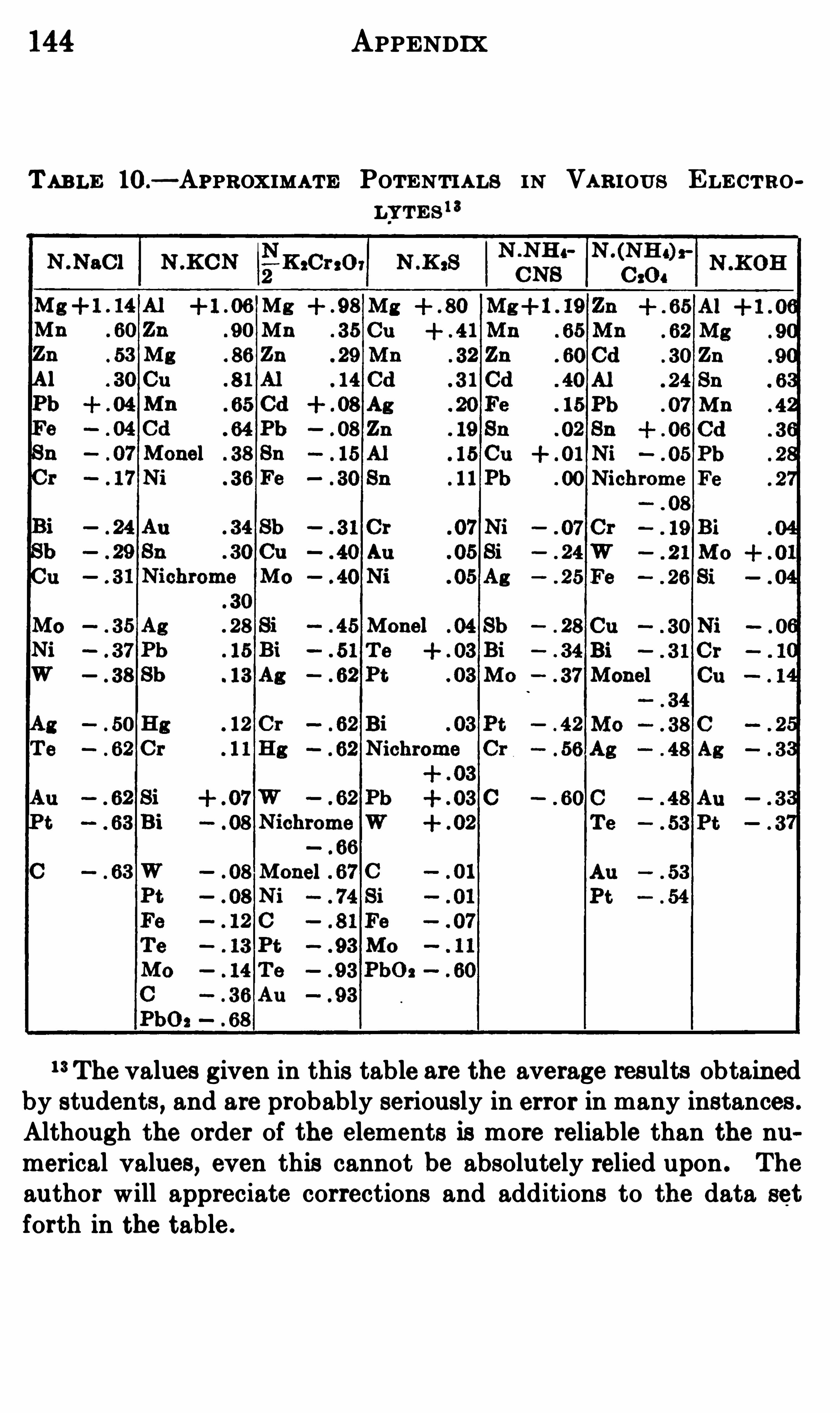
144 APPENDIX
TABLE 10.
—APPROXIMA TE POTENTIA LS IN VA R IOUS ELECTROLYTEs 1 3
1 3The values given in this table are the average results obtainedby students, and are probably seriously in error in many instances .
Although the order of the elements is more reliable than the numerical values, even this cannot be absolutely relied upon . The
author will appreciate corrections and additions to the data set
forth in the table.


Addition agents 84, 89Alloys, electrodeposition of, 65
—1 15Aluminum electrodes, 29
corrosion of, 70, 1 12electroplating of, 1 10, 1 1 1rectifier, 29
Ammonium persulphate, 126Atomic weight
,table of
,138
Barium perchlorate, 131Brass plating, 60, 66, 97—101 ,
107 , 108, 1 13
Calomel electrode, 36, 39Chlorates, preparation of, 127,
128
Coloring metals,1 18, 1 19
Copper plating,95 97, 104
,
Corrosion of metals, 60—62Coulombmeter
, 30, 31 , 1 1 1
Critical current density , 107Current efficiency
, 30, 1 1 1 , 1 12
Decomposition voltage,
see
of decom
position .
Deposition by immersion, 103of metals
,see
“Electrodeposition .
”
Discharge potential,56—57
Electrical instruments, principles of construction ,7
protection from injury, 8
INDEX
Electric cleaning of metals, 60,91
Electrochemical equ ivalents,138
Electrode,aluminum
,29
, 70,
1 12
intermediate, 69normal calomel
, 36, 39
Electro- deposition of alloys,97
101
of brass, 66, 97—101 , 1 13of cadmium , 1 16
of copper, 68, 95—97, 104 ,
of lead,12, 1 13
of iron,1 16
of nickel, 68, 93—95, 104 ,105, 108, 109, 1 1 1
,
1 12
of silver,97
,101
, 102, 105 ,
1 15
principles of 84—89Electrolytic analysis, 66oxidation
,121 , 122, 124
reduction,1 1 , 33, 121
—123separation of metals, 63
Electromotive force, 33, 34of decomposition, 43of copper sulphate
,49
of hydrochloric acid,48,
50
of nitric acid,48
, 50
of sodium chloride, 43of sulphuric acid, 47, 48,50
of zinc bromide, 46, 50

148
Electromotive force, cfiect ofelectrodes of unequalsize upon
,49—55
table of numerical values,145
Faraday ’s law ,29
Fig . 1—R esistivity of electrolytes
,14
2—Resistivity,using a
low-scalevoltmeter,17
3—R esistivity using ad o u b l e-s c a l e voltmeter
,18
4 —R esistivity,of wire
,19
5—Resistivity , w ith voltmeter only , 21
6—R esistivity , by voltmeter and resistancebox
,22
7—Cell for temperaturecoefficient of resistance, 23
8—R esistance of a fusedelectrolyte
,25
9—Potentiometerconnections
,38
10—Polarization in a voltaic cell, 42
1 1 of decomposition
,43
12 of decomposition and polarization
,
45
13 of decomposition and polarizationby the potentiometer,51
14—Curves of polarizationat electrodes, 53
15—Curves for electrodesof unequal size, 54
INDEX
Fig . 16—Apparatus for electrolytic analysis
,67
Ga lv anite plating,105
Galvanometer key, special, 52Galvanoplasty, 1 19Gas volumes, reduction to
standard conditions,32
Hypochlorite of sodium,135
Instruction for students, 5
Laboratory equipment, 2Lead nitrate
,electrolysis of, 12
Mercury cathode, 12refining of
,134
Metallochromes,1 18
Nickel plating, 93—95, 104 , 105 ,
Ohm ’s law , 14
Overvoltage, 58
of hydrogen, 58, 121of
‘
oxygen, 122
Oxidation,121 , 122,
Oxidizing metals, baths for, 8082
experiments, 1 18—1 19
129- 132,
Passive state of metals, 58—60Perchlorates, 130, 131Persulphates, estimation of, 126preparation of, 125—127
Plating baths, composition of,72—79metal content and cur
rent density, 83

150 INDEX
Table of potentials calculated by Table resistivity of metals,Thomson ’s rule, 143 Tin plating
,104
in difl'
erent electrolytes ,144 Voltite plating, 105
in normal solutions, 142resistivity of electrolytes , Water, electrolysis of 31
139 White lead , preparation of,