Predictive Direct DC-link Current Control of IPMSM Drive ...
10
IEEJ Journal of Industry Applications Vol.8 No.3 pp.394–403 DOI: 10.1541/ieejjia.8.394 Paper Predictive Direct DC-link Current Control of IPMSM Drive System Using Electrolytic Capacitorless Inverter for Fine Harmonics Suppression Yousuke Akama ∗ Non-member, Kodai Abe ∗∗ Member Yushi Araki ∗ Student Member, Kiyoshi Ohishi ∗ Fellow Yuki Yokokura ∗ Member, Koji Kobayashi ∗∗∗ Member Tatsuki Kashihara ∗∗∗ Member (Manuscript received June 17, 2018, revised Nov. 13, 2018) This paper proposes a method for direct predictive control of DC-link current using the interior permanent magnet synchronous motor (IPMSM) discrete equation for electrolytic capacitorless inverters. Electrolytic capacitorless in- verters do not have any electrolytic capacitors or power factor correction circuits. Therefore, direct DC-link current control is proposed as a method for controlling the the DC-link current of the inverter to improve the input power factor. However, in the direct DC-link current-control method, an error occurs in the DC-link current due to the one-sample delay in the voltage output. Because of this error, a current harmonic is generated in the input current. The direct pre- dictive DC-link current control proposed in this paper reduces this error, thus satisfying the input-current-harmonics regulation value of IEC 61000-3-2. Keywords: IPMSM, electrolytic capacitorless inverter, source current harmonics 1. Introduction In recent years, a variable-speed drive system for motors has been widely used to save energy (1)–(3) . In general, single- phase to three-phase inverters have been used for variable speed operation of motors. To use a single-phase-to-three- phase inverter, a power factor correction (PFC) circuit and a large electrolytic capacitor are required (4) . However, large electrolytic capacitors increase the size and shorten the life of the inverter system of compressor motor. These problems also occur in a three-phase to three-phase inverter system, and a method for controlling capacitor current by predictive control has been proposed (5)–(8) . In a single-phase to three- phase inverter system, a motor drive system using a film capacitor instead of an electrolytic capacitor has been pro- posed (9) . In this system, because the DC-link part does not have a large energy buffer, the power ripple is absorbed by the kinetic energy accumulated in the moment of inertia of the motor. However the input current oscillates due to the res- onance between the line impedance reactor on the grid side and the DC-link capacitor, and harmonics are generated in the input current. Input current harmonics are regulated by IEC 61000-3-2 class A. IEC 61000-3-2 class A regulates odd ∗ Nagaoka University of Technology 1603-1, Kamitomioka-machi, Nagaoka, Niigata 940-2188, Japan ∗∗ Tokyo Metropolitan College of Industrial Technology 1-10-40, Higashi-oi, Shinagawa-ku, Tokyo 140-0011, Japan ∗∗∗ Sanden advanced Technology 20, Kotobuki-cho, Isesaki, Gunma 372-0052, Japan and even harmonics (10) . The input current harmonics in this system do not satisfy the IEC 61000 3-2 class A. In addition, to improve the input current waveform, direct DC-link current control (DDCCC) has been proposed (11)–(13) . DDCCC controls the DC-link current toward electrolytic ca- pacitorless inverter by modifying the inverter output volt- age directly, and then is not limited by motor-current-control bandwidth. Especially, this method reduces the input current harmonics effectively in high-speed region that the frequency of the spatial harmonics higher than the control bandwidth. However, because the direct DC-link current control method controls the DC-link current in a feedforward manner, an er- ror occurs in the DC-link current due to the motor current that changes during the control period. When the modifica- tion amount of the voltage reference is large, the output volt- age vector is modified to the intersection between the DC- link current line and the voltage-limit. When the voltage ref- erence sharply changes, the motor current changes steeply. The inverter includes one-sample delay in the voltage out- put. Therefore, when the fluctuation of the current in the sampling period is large, the control error of the DC-link current becomes large and causes a high-frequency harmon- ics (14) . Therefore, this paper proposes a new predictive con- trol based on the interior permanent magnet synchronous mo- tor (IPMSM) discrete equation that reduce the error caused by delay in the DC-link current. Moreover, this paper con- firms the effectiveness of the proposed method by experi- ment. c 2019 The Institute of Electrical Engineers of Japan. 394
Transcript of Predictive Direct DC-link Current Control of IPMSM Drive ...

IEEJ Journal of Industry ApplicationsVol.8 No.3 pp.394–403 DOI: 10.1541/ieejjia.8.394
Paper
Predictive Direct DC-link Current Control of IPMSM Drive SystemUsing Electrolytic Capacitorless Inverter
for Fine Harmonics Suppression
Yousuke Akama∗ Non-member, Kodai Abe∗∗ Member
Yushi Araki∗ Student Member, Kiyoshi Ohishi∗ Fellow
Yuki Yokokura∗ Member, Koji Kobayashi∗∗∗ Member
Tatsuki Kashihara∗∗∗ Member
(Manuscript received June 17, 2018, revised Nov. 13, 2018)
This paper proposes a method for direct predictive control of DC-link current using the interior permanent magnetsynchronous motor (IPMSM) discrete equation for electrolytic capacitorless inverters. Electrolytic capacitorless in-verters do not have any electrolytic capacitors or power factor correction circuits. Therefore, direct DC-link currentcontrol is proposed as a method for controlling the the DC-link current of the inverter to improve the input power factor.However, in the direct DC-link current-control method, an error occurs in the DC-link current due to the one-sampledelay in the voltage output. Because of this error, a current harmonic is generated in the input current. The direct pre-dictive DC-link current control proposed in this paper reduces this error, thus satisfying the input-current-harmonicsregulation value of IEC 61000-3-2.
Keywords: IPMSM, electrolytic capacitorless inverter, source current harmonics
1. Introduction
In recent years, a variable-speed drive system for motorshas been widely used to save energy (1)–(3). In general, single-phase to three-phase inverters have been used for variablespeed operation of motors. To use a single-phase-to-three-phase inverter, a power factor correction (PFC) circuit anda large electrolytic capacitor are required (4). However, largeelectrolytic capacitors increase the size and shorten the lifeof the inverter system of compressor motor. These problemsalso occur in a three-phase to three-phase inverter system,and a method for controlling capacitor current by predictivecontrol has been proposed (5)–(8). In a single-phase to three-phase inverter system, a motor drive system using a filmcapacitor instead of an electrolytic capacitor has been pro-posed (9). In this system, because the DC-link part does nothave a large energy buffer, the power ripple is absorbed bythe kinetic energy accumulated in the moment of inertia ofthe motor. However the input current oscillates due to the res-onance between the line impedance reactor on the grid sideand the DC-link capacitor, and harmonics are generated inthe input current. Input current harmonics are regulated byIEC 61000-3-2 class A. IEC 61000-3-2 class A regulates odd
∗ Nagaoka University of Technology1603-1, Kamitomioka-machi, Nagaoka, Niigata 940-2188,Japan
∗∗ Tokyo Metropolitan College of Industrial Technology1-10-40, Higashi-oi, Shinagawa-ku, Tokyo 140-0011, Japan
∗∗∗ Sanden advanced Technology20, Kotobuki-cho, Isesaki, Gunma 372-0052, Japan
and even harmonics (10). The input current harmonics in thissystem do not satisfy the IEC 61000 3-2 class A.
In addition, to improve the input current waveform, directDC-link current control (DDCCC) has been proposed (11)–(13).DDCCC controls the DC-link current toward electrolytic ca-pacitorless inverter by modifying the inverter output volt-age directly, and then is not limited by motor-current-controlbandwidth. Especially, this method reduces the input currentharmonics effectively in high-speed region that the frequencyof the spatial harmonics higher than the control bandwidth.However, because the direct DC-link current control methodcontrols the DC-link current in a feedforward manner, an er-ror occurs in the DC-link current due to the motor currentthat changes during the control period. When the modifica-tion amount of the voltage reference is large, the output volt-age vector is modified to the intersection between the DC-link current line and the voltage-limit. When the voltage ref-erence sharply changes, the motor current changes steeply.The inverter includes one-sample delay in the voltage out-put. Therefore, when the fluctuation of the current in thesampling period is large, the control error of the DC-linkcurrent becomes large and causes a high-frequency harmon-ics (14). Therefore, this paper proposes a new predictive con-trol based on the interior permanent magnet synchronous mo-tor (IPMSM) discrete equation that reduce the error causedby delay in the DC-link current. Moreover, this paper con-firms the effectiveness of the proposed method by experi-ment.
c© 2019 The Institute of Electrical Engineers of Japan. 394

Predictive Direct DC-link Current Control for Harmonics Suppression(Yousuke Akama et al.)
Fig. 1. System configuration of DDCCC
2. Direct DC-link Current Control
In the electrolytic capacitorless inverter system, the DC-link electrolytic capacitor is replaced with a small-capacityfilm capacitor, and the PFC circuit is omitted. As the cur-rent flowing into the capacitor decreases, the input powerfactor is improved by controlling the DC-link current in theelectrolytic capacitorless inverter. However, the input-currentdistortion occurs due to a delay in the motor current controlsystem and the induced harmonics voltage of IPMSM. There-fore, DDCCC improves the power factor by directly control-ling the DC-link current of the electrolytic capacitorless in-verter. The block diagram of the IPMSM drive system towhich DDCCC is applied is shown in Fig. 1. DDCCC is amethod of directly controlling the DC-link current by modi-fying the output voltage of the inverter. DDCCC is appliedwhen the motor speed is in the steady state.
In the inverter, the relationship between the rectified sourcecurrent |iin|, the DC-link current Idc, and the DC-link capaci-tor current ic is as follows:
|iin| = Idc + ic. · · · · · · · · · · · · · · · · · · · · · · · · · · · · · · · · · · · (1)
The average DC-link current Idc is determined by the sum ofthe average values of each phase current as follows:
Idc =12
iαv∗αn +
12
iβv∗βn · · · · · · · · · · · · · · · · · · · · · · · · · · · · (2)
where v∗αn and v∗βn are the normalized α and β axis voltagereferences and iα and iβ are the α and β axis currents, respec-tively. The process of normalization involves dividing thevoltage reference value by the DC-link voltage Vdc and thenmultiplying by 2. On the basis of Eq. (1), the DC-link currentreference I∗dc required to obtain a unity input power factor iscalculated as follows:
I∗dc = |i∗in| − ic · · · · · · · · · · · · · · · · · · · · · · · · · · · · · · · · · · · · (3)
The rectified source current reference |iin|∗ and the DC-linkcapacitor current ic are obtained as follows:
|i∗in| =∣∣∣∣∣ωre
Pτ∗in
1vin
∣∣∣∣∣ · · · · · · · · · · · · · · · · · · · · · · · · · · · · · · · (4)
ic = CdcdVdc
dt= ωinCdcVin cos θin · sgn(sin θin) · · · · · · · · · · · · · · · (5)
Here, Cdc is the capacitance of the DC-link capacitor, ωin isthe angular frequency of the grid, Vin is peak value of thegrid voltage, and θin is the grid phase in Fig. 1. By reformingEq. (2) for v∗βn, the following equation is calculated.
v∗βn = −iαiβv∗αn +
2I∗dc
iβ· · · · · · · · · · · · · · · · · · · · · · · · · · · · (6)
v∗qn = −idiqv∗dn +
2I∗dc
iq· · · · · · · · · · · · · · · · · · · · · · · · · · · · (7)
Equation (6) indicates that the DC-link current, which isequal to its reference I∗dc, is obtained by outputting the volt-age vector on the line. Equation (7) is obtained by convertingEq. (6) into the dq axis. In the control of electrolytic capaci-torless inverters, Eq. (6) and similar equations are commonlyused (11)–(13) (15)–(17). The DDCCC method controls the DC-linkcurrent by correcting the output voltage reference v′o[v′αn, v
′βn]
of the current controller on the DC-link current line, as shownin Fig. 2. Figure 2(a) shows the state of DDCCC in whichvoltage limitation does not occur, and the voltage vector ismodified to a point on the DC-link current line with the samephase as v′o. The phase of the output voltage vectors is equalto the phase of v′o as follows:
v∗βn =v′βnv′αnv∗αn · · · · · · · · · · · · · · · · · · · · · · · · · · · · · · · · · · · · (8)
The intersection point between Eq. (6) and Eq. (8) is calcu-lated as follows:
v∗αn =I∗dc
(v′αniα + v′βniβ)/2v′αn · · · · · · · · · · · · · · · · · · · · · · · (9)
395 IEEJ Journal IA, Vol.8, No.3, 2019

Predictive Direct DC-link Current Control for Harmonics Suppression(Yousuke Akama et al.)
(a) within voltage limitation (b) without voltage limitation
(c) modified voltage ratio limitation
Fig. 2. Output voltage modification by direct DC-linkcurrent control
(a) Input Current Response
(b) dq-axis Current Response
(c) Output dq-axis normalized voltage vector
Fig. 3. Experimental results of conventional DDCCCmethod on condition of Rated speed 3000 rpm, full loadand 16 kHz PWM Switching
v∗βn =I∗dc
(v′αniα + v′βniβ)/2v′βn · · · · · · · · · · · · · · · · · · · · · · ·(10)
In DDCCC, the voltage reference from the current con-troller is modified as shown in Eq. (9) and Eq. (10). Figure 3shows the experimental results of IPMSM control by DD-CCC under the conditions as shown in Table 1 and Table 2.In Fig. 2, the results of (b) are shown on the condition of thevoltage-limit-inscribed circle, and (c) is shown in the con-dition of modified voltage ratio limitation, such as ADDCCC ,which has a lower-limit value of 0.3 and upper-limit value of100. ADDCCC is a gain for modifying the voltage referencevalue which is the current controller output. Modification by
Table 1. Motor parameters
parameter value
Stator resistance Ra 1.034Ωd-axis inductance Ld 14.15 mHq-axis inductance Lq 23.40 mHLinkage flux φa 0.0869 V/(rad/s)Number of pole pairs P 3 pole
Table 2. Experimental conditions
parameter value
DC-link capacitance Cdc 11 μFLine inductance l 0.4 mHLine resistance r 0.5ΩPoles of current control system ωcc 4000 rad/sPoles of speed control system ωsc 80 rad/sPWM carrier frequency fs 16 kHzLine frequency fin 50 HzADDCCC lower limit value 0.3ADDCCC upper limit value 100
Fig. 4. FFT analysis of input current by conventionalDDCCC method on condition of Rated speed 3000 rpm,full load and 16 kHz PWM Switching
ADDCCC is equivalent to modifying the pole of the currentcontrol system. To operate the system sably, it is necessaryto set the lower and upper limitof ADDCCC . The lower limitvalue is set so that the pole of the current controller does notbecome lower than the pole of the speed controller (13). Theupper limit value is set to a large value so that the poles of thecurrent controller are not limited by saturation of the modifi-cation amount. In the experimental results as shown in Fig. 3,the input current harmonics are generated when the voltagereference sharply changes. In the DDCCC, the input currentharmonics occur depending on motor parameters and oper-ating conditions. The fast Fourier transform (FFT) resultsof the input current is shown in Fig. 4, where the regulationvalue of IEC 61000-3-2 is not sometimes satisfied.
3. Predictive Direct DC-link Current Controlbased on IPMSM discrete equation
3.1 Predictive Direct DC-link Current Control withinthe Voltage Limit In the proposed method, the motorcurrent is controlled on the αβ axis and is predicted on the dqaxis. DDCCC is based on Eq. (2), which is based on the in-stantaneous value of the motor current at the sampling pointand includes the error between the DC-link current in Eq. (2)and accurate average DC-link current during control periodin Eq. (11).
Idc[k + 1] =id[k + 1] + id[k + 2]
4v∗dn[k]
+iq[k + 1] + iq[k + 2]
4v∗qn[k] · · · · · · · (11)
Equation (11) is a relative equation of the motor current and
396 IEEJ Journal IA, Vol.8, No.3, 2019

Predictive Direct DC-link Current Control for Harmonics Suppression(Yousuke Akama et al.)
Fig. 5. DC-link current response by conventional DDCCC
the average value of DC-link current. This paper defines the[k] point as the current time point and defines the voltage ref-erence calculated at [k] as v∗dn[k] and v∗qn[k]. In general, thevoltage reference calculated at time point [k] is output fromthe inverter at time point [k+1]. Therefore, as shown in Fig. 5DDCCC has a control error of the DC-link current due to aone-sample delay because the output voltage is not taken intoconsideration in Eq. (2). Therefore, in order to control theDC-link current more strictly, the DC-link current line shouldbe calculated from Eq. (11). The future values of the motorcurrents id[k+1] and iq[k+1] are calculated from the discreteIPMSM equations given by Eq. (12) and Eq. (13). Becausethe motor speed is steady state, ωre is a constant value.
id[k + 1] = A11id[k] + A12iq[k] + b11Vdc[k]
2v∗dn[k − 1]
+ b12Vdc[k]
2v∗qn[k−1]−b12ωreφa · · · · · (12)
iq[k + 1] = A21id[k] + A22iq[k] + b21Vdc[k]
2v∗dn[k − 1]
+ b22Vdc[k]
2v∗qn[k−1]−b22ωreφa · · · · · (13)
The coefficients A and b used for Eq. (12) and Eq. (13) are de-scribed in the Appendix. The right side elements in Eq. (12)and Eq. (13) all have been known values at the time point [k],and id[k + 1] and iq[k + 1] are obtained at the time point [k].Similarly, the future value of the motor current at the timepoint [k + 2] is calculated as follows:
id[k + 2] = A11 id[k + 1] + A12 iq[k + 1]
+ b11Vdc[k + 1]
2v∗dn[k]
+ b12Vdc[k+1]
2v∗qn[k]−b12ωreφa · · · · · (14)
iq[k + 2] = A21 id[k + 1] + A22 iq[k + 1]
+ b21Vdc[k + 1]
2v∗dn[k]
+ b22Vdc[k+1]
2v∗qn[k]−b22ωreφa · · · · · (15)
By substituting Eq. (12), Eq. (13), Eq. (14), Eq. (15), and
I∗dc[k] into Eq. (11) and solving for v∗qn[k], the equation of theDC-link current line considering the motor current that varieswith one sample delay and the output voltage is obtained asfollows:
v∗qn[k] =n1 ± √n2
2a3· · · · · · · · · · · · · · · · · · · · · · · · · · · · · (16)
n1 = −a2 − a5V∗dn[k]
n2 =(a1 + a5v
∗dn[k])2
− 4a3(a2v∗dn[k] + a4v
∗dn[k]2 − I∗dc[k])
a1 =1
2(iq[k + 1] + A21 id[k + 1] + A22 iq[k + 1]
+ b22
(−ωreφ f a
)) · · · · · · · · · · · · · · · · · · · · · · · · · (17)
a2 =1
2(id[k + 1] + A11 id[k + 1] + A12 iq[k + 1]
+ b22
(−ωreφ f a
)) · · · · · · · · · · · · · · · · · · · · · · · · · (18)
a3 =b22
2Vdc[k + 1]
2· · · · · · · · · · · · · · · · · · · · · · · · · · · · (19)
a4 =b11
2Vdc[k + 1]
2· · · · · · · · · · · · · · · · · · · · · · · · · · · · (20)
a5 =
⎛⎜⎜⎜⎜⎝b21
2+
b12
2
⎞⎟⎟⎟⎟⎠ Vdc[k + 1]2
· · · · · · · · · · · · · · · · · · · · (21)
As shown in Table 2, because the poles of the speed con-troller and the line frequency are at least 100 times lower thanthe carrier frequency, the sampling value at time point [k] isused for Vdc[k + 1] and ωre[k + 1] in Eq. (15). In addition,because the voltage reference calculated at time point [k] isoutput from the inverter at time point [k + 1], the DC-linkcurrent reference I∗dc[k] calculated at time point [k] is used asthe I∗dc[k + 1] at time point [k+1]. Equation (15) defines anellipse passing through the vicinity of the conventional DC-link current line as shown in Fig. 6. This equation is called thepredictive DC-link current curve. The proposed method pre-dictively controls the DC-link current by using Eq. (15). Thepredictive DC-link current curve is used in the same manneras the DDCCC, as shown in Fig. 6. In Fig. 6, similarly (b) isshown on the condition of voltage limitation on the hexago-nal voltage aria, and (c) is shown in the condition of modifiedvoltage-ratio limitation, such as the ADDCCC lower limit valueof 0.3 and upper limit value of 100. By using the predictiveDC-link current curve, the error caused by delay in the DC-link current is reduced as shown in Fig. 7.
In the predictive control of the DC-link current using thepredictive DC-link current curve, the DC-link current is con-trolled by modifying the voltage reference from the currentcontroller. When the voltage is not saturated, the amplitudeof the voltage reference v′o from the current controller is mod-ified to be the voltage reference of the predictive DC-link cur-rent curve. Assuming that the voltage reference calculatedfrom the current controller and the decoupling controller arev′o[v′dn[k], v′qn[k]], the line with the same phase as the outputvoltage is as follows:
v∗qn[k] =v′qn[k]
v′dn[k]v∗dn[k] = av∗dn[k] · · · · · · · · · · · · · · · · · · (22)
The intersection of Eq. (21) and the predictive DC-link
397 IEEJ Journal IA, Vol.8, No.3, 2019

Predictive Direct DC-link Current Control for Harmonics Suppression(Yousuke Akama et al.)
(a) within voltage limitation (b) withinout voltage limitation
(c) modified voltage ratio limitation
Fig. 6. Output voltage modification by proposed predic-tive DC-link current curve
Fig. 7. DC-link current response by predictive DC-linkcurrent control
current curve is as follows:
v∗dn[k] =m1 ± √m2
d1· · · · · · · · · · · · · · · · · · · · · · · · · · · · (23)
m1 = −aa2 − a1
m2 = 4I∗dc[k]a2a4 + a2a22 + 4I∗dc[k]aa5
+ 2aa1a2 + 4a3I∗dc[k] + a21
d1 = 2(a2a4 + aa5 + a3
)
The value of v∗qn[k] at the intersection is obtained by substi-tuting v∗dn[k] from Eq. (22) into Eq. (21). When the voltagevector obtained from Eq. (22) is out of the voltage limitation,the prediction control method of the voltage saturation regionis used. When the ratio of the amplitude of the voltage vectormodified by Eq. (22) exceeds the conditions in Table 2, theprediction-control method of the voltage saturation region isused.3.2 Predictive Direct DC-link Current Control in the
Voltage Saturation Region DDCCC modifies the out-put voltage vector to be that on the intersection of the voltagelimit and the DC-link current line. The proposed predictivecontrol of the DC-link current also modifies this output volt-age vector to be that on voltage limit and the predictive DC-link current curve. In this paper, the voltage limit is defined asvoltage-limitation hexagon. The voltage-limitation hexagonis expressed using six straight lines and is generalized as astraight-line equation, as shown by Eq. (25).
v∗qn[k]=−v∗dn[k]tan
⎛⎜⎜⎜⎜⎝θre+nπ
3
⎞⎟⎟⎟⎟⎠+√
2
cos
⎛⎜⎜⎜⎜⎝θre+nπ
3
⎞⎟⎟⎟⎟⎠· · · · (24)
=cv∗dn[k] + d · · · · · · · · · · · · · · · · · · · · · · · · · · · · (25)
The intersection of the Eq. (25) and the predictive DC-linkcurrent curve is shown in Eq. (15).
v∗dn[k] =m3 ± √m4
d1· · · · · · · · · · · · · · · · · · · · · · · · · · · · (26)
m3 = 2d2c2a4 − c2a2 − da5 − a1
m4 = 4c2a4I∗dc[k] + c2a22 + 4cda1a4
− 2cda5a4 − 4d2a3a4 + d2a25
+ 4cI∗dc[k]a5 + 2ca1a2 + 2da1a5
− 4da3a2 + 4a3I∗dc[k] + a21
The value of v∗qn[k] at the intersection is obtained by substi-tuting v∗dn[k] calculated from Eq. (26) for v∗dn[k] in Eq. (25).Equation (26) is calculated for each of the six equations, andthe closest intersection point that has a solution inside eachvertex of the voltage-limitation hexagon is taken as the inter-section point.
4. Performance Analysis between DDCCC andProposed Predictive DDCCC
In DDCCC, the voltage vector is manipulated in a feed-forward manner so as to obtain the desired DC-link currentbased on the sampling value of the continuously changingmotor current. In Fig. 5, because the output voltage is de-layed by one sample period, an error occurs in the DC-linkcurrent. Moreover, because the motor current changes duringthe control period depending on the output voltage, the errorof the DC-link current increases. Therefore, DDCCC usingthe DC-link current line always has an error in the DC-linkcurrent, and the error amount varies depending on the voltageoutput from the inverter.
The error caused by delay in the DC-link current due toDDCCC is obtained by calculating Idc[k] using Eq. (11). Theerror rate between Idc[k] and I∗dc[k] is as follows:
IdcError =
∣∣∣∣∣∣∣I∗dc[k] − Idc[k]
I∗dc[k]
∣∣∣∣∣∣∣ · · · · · · · · · · · · · · · · · · · · · · · (27)
The error rate IdcError distribution in the hexagonal voltagelimit under the conditions shown in Table 1 and Table 3 isshown in Fig. 8. Moreover, Fig. 8 also shows the error IdcError
at the point on the DC-link current line at phase θ∗. In Fig. 8,the difference between DC-link current line and predictiveDC-link current curve is large. In the proposed method, whenthe motor does not cause parameter variation and the outputvoltage vector is within the voltage limit, the error rate IdcError
is 0%.When the harmonics of the magnetic flux density distribu-
tion of the rotor is large, the harmonics of the motor currentincreases. In this condition, the change in motor current dur-ing the sample period increases and the error caused by delayincreases. Such an error arises as long as a method of modi-fying the voltage vector based on the sampled current is used.The error rate IdcError distribution under the conditions shown
398 IEEJ Journal IA, Vol.8, No.3, 2019
Predictive Direct DC-link Current Control for Harmonics Suppression(Yousuke Akama et al.)
Table 3. Calculation parameters (Condition 1)
parameter value
d-axis current id[k] −2.02 [A]q-axis current iq[k] 2.03 [A]DC-link current reference I∗dc 0.962 [A]Electrical angle θre 4.24 [rad]Electrical angular velocity ωe 472 [rad/s]DC-link voltage 266VGrid phase θin 70.12 [deg.]
Fig. 8. Distribution of error rate IdcError (Condition 1)
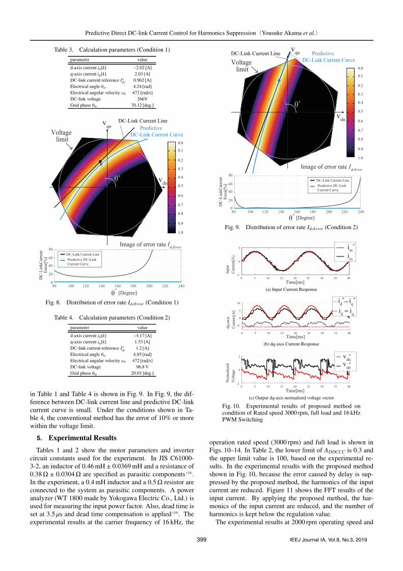
Table 4. Calculation parameters (Condition 2)
parameter value
d-axis current id[k] −4.17 [A]q-axis current iq[k] 1.53 [A]DC-link current reference I∗dc 1.2 [A]Electrical angle θre 4.85 [rad]Electrical angular velocity ωe 472 [rad/s]DC-link voltage 96.8 VGrid phase θin 20.01 [deg.]
in Table 1 and Table 4 is shown in Fig. 9. In Fig. 9, the dif-ference between DC-link current line and predictive DC-linkcurrent curve is small. Under the conditions shown in Ta-ble 4, the conventional method has the error of 10% or morewithin the voltage limit.
5. Experimental Results
Tables 1 and 2 show the motor parameters and invertercircuit constants used for the experiment. In JIS C61000-3-2, an inductor of 0.46 mH ± 0.0369 mH and a resistance of0.38Ω ± 0.0304Ω are specified as parasitic components (18).In the experiment, a 0.4 mH inductor and a 0.5Ω resistor areconnected to the system as parasitic components. A poweranalyzer (WT 1800 made by Yokogawa Electric Co., Ltd.) isused for measuring the input power factor. Also, dead time isset at 3.5 μs and dead time compensation is applied (19). Theexperimental results at the carrier frequency of 16 kHz, the
Fig. 9. Distribution of error rate IdcError (Condition 2)
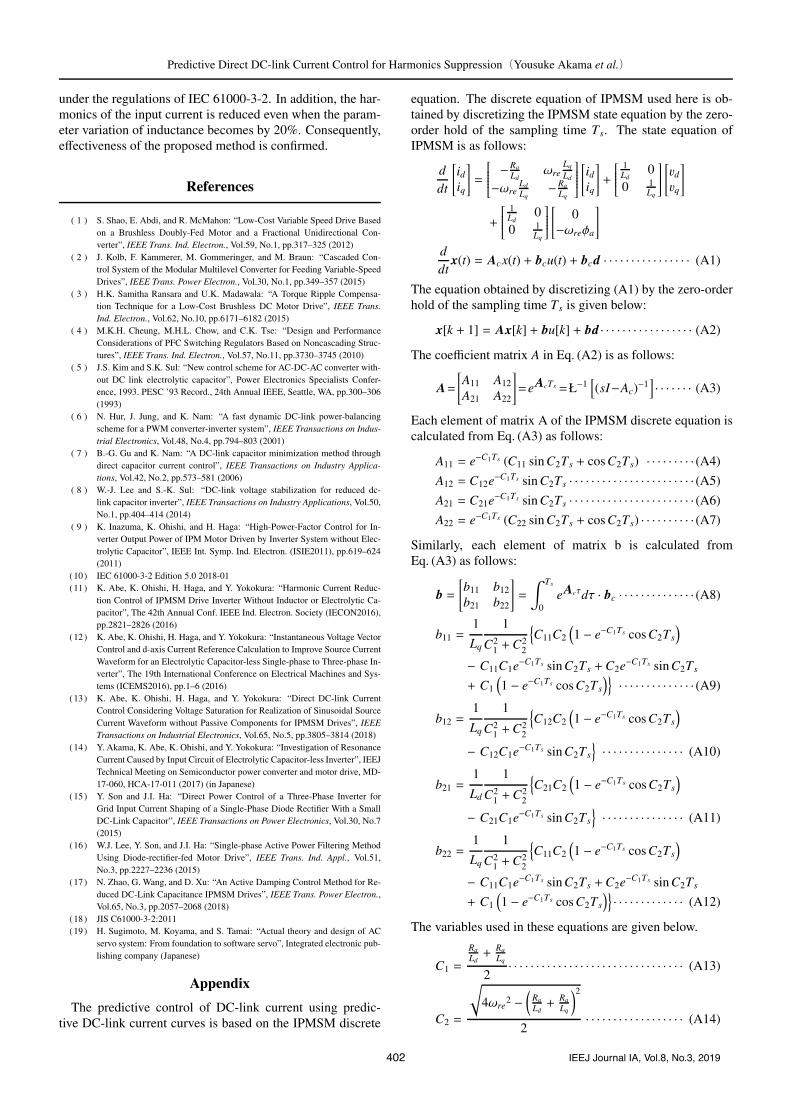
(a) Input Current Response
(b) dq-axis Current Response
(c) Output dq-axis normalized voltage vector
Fig. 10. Experimental results of proposed method oncondition of Rated speed 3000 rpm, full load and 16 kHzPWM Switching
operation rated speed (3000 rpm) and full load is shown inFigs. 10–14. In Table 2, the lower limit of ADDCCC is 0.3 andthe upper limit value is 100, based on the experimental re-sults. In the experimental results with the proposed methodshown in Fig. 10, because the error caused by delay is sup-pressed by the proposed method, the harmonics of the inputcurrent are reduced. Figure 11 shows the FFT results of theinput current. By applying the proposed method, the har-monics of the input current are reduced, and the number ofharmonics is kept below the regulation value.
The experimental results at 2000 rpm operating speed and
399 IEEJ Journal IA, Vol.8, No.3, 2019

Predictive Direct DC-link Current Control for Harmonics Suppression(Yousuke Akama et al.)
Fig. 11. FFT analysis of input current at Rated speed3000 rpm, full load and 16 kHz PWM Switching
(a) Input Current Response
(b) dq-axis Current Response
(c) Output dq-axis normalized voltage vector
Fig. 12. Experimental results of conventional DDCCCmethod on condition of Rated speed 2000 rpm, 60% loadand 16 kHz PWM Switching
(a) Input Current Response
(b) dq-axis Current Response
(c) Output dq-axis normalized voltage vector
Fig. 13. Experimental results of proposed method oncondition of Rated speed 2000 rpm, 60% load and 16 kHzPWM Switching
Fig. 14. FFT analysis of input current at Rated speed2000 rpm, 60% load and 16 kHz PWM Switching
(a) Input Current Response
(b) dq-axis Current Response
(c) Output dq-axis normalized voltage vector
Fig. 15. Experimental results of conventional DDCCCmethod on condition of Rated speed 3000 rpm, full loadand 10 kHz PWM Switching
60% load are shown in Fig. 12 and Fig. 13. In the case of thecondition of low speed and light load, in the conventionalmethod, the harmonics of the input current often remainswhen the voltage reference is steeply operated. In contrast,in the proposed method, the harmonics of the input currentare suppressed well. Fig. 14 shows the FFT results of the in-put current with low speed and low load. By applying theproposed method at low speed and light load, the harmonicsof the input current are reduced well.
The experimental results set the carrier frequency to10 kHz are shown from Fig. 15 to Fig. 17. According to theexperimental results at operating rated speed and full load,as shown in Fig. 15, the harmonics of the input current of-ten remains when the voltage vector is steeply operated, as isalso shown in the results of Fig. 3. In addition, as the con-trol period is extended, the motor current difference betweenid[k] and id[k + 1] increases. In this case, the harmonics ofthe input current due to the motor current harmonics becomeslarge. Even when the control period is extended, by applyingthe proposed method, the harmonics of the input current arereduced. Tables 5 and 6 show the harmonic-reduction ratiosand power factor for each experiment. In each condition, theinput current harmonics and power factor are improved bythe proposed method.
Figures 18–20 shows the experimental results with 20%
400 IEEJ Journal IA, Vol.8, No.3, 2019

Predictive Direct DC-link Current Control for Harmonics Suppression(Yousuke Akama et al.)
(a) Input Current Response
(b) dq-axis Current Response
(c) Output dq-axis normalized voltage vector
Fig. 16. Experimental results of proposed method oncondition of Rated speed 3000 rpm, full load and 10 kHzPWM Switching
Fig. 17. FFT analysis of input current at Rated speed3000 rpm, full load and 10 kHz PWM Switching
Table 5. Harmonics reduction ratio by the proposedmethod
Operating speedDecrease amount of
2-40 th order harmonicsDecrease amount of
41-60 th order harmonics
2000 rpm(16 kHz) 2.62% 44.51%3000 rpm(16 kHz) 20.77% 45.42%3000 rpm(10 kHz) 19.03% 32.68%
Table 6. Input power factor of input current
Operating speed Conventional method Proposed method
2000 rpm(16 kHz) 98.57% 99.07%3000 rpm(16 kHz) 99.31% 99.35%3000 rpm(10 kHz) 96.95% 98.81%
parameter variation in inductance. The effectiveness of theproposed method is maintained even when the parametervaries by about 20%.
6. Conclusion
This paper proposes a new predictive control method forDC-link current using the IPMSM discrete equations. Theconventional DDCCC often has input-current harmonics bythe voltage output delay. The harmonics of the input currentare reduced because the error caused by delay is reduced bythe proposed method. In the experiments, by using the pro-posed method, the harmonics of the input current is reduced
(a) Input Current Response
(b) dq-axis Current Response
(c) Output dq-axis normalized voltage vector
Fig. 18. Experimental results of proposed method oncondition of Rated speed 3000 rpm, full load and 16 kHzPWM Switching (Ld, Lq − 20%)
(a) Input Current Response
(b) dq-axis Current Response
(c) Output dq-axis normalized voltage vector
Fig. 19. Experimental results of proposed method oncondition of Rated speed 3000 rpm, full load and 16 kHzPWM Switching (Ld, Lq + 20%)
Fig. 20. FFT analysis of input current (parameter variation)
401 IEEJ Journal IA, Vol.8, No.3, 2019
Predictive Direct DC-link Current Control for Harmonics Suppression(Yousuke Akama et al.)
under the regulations of IEC 61000-3-2. In addition, the har-monics of the input current is reduced even when the param-eter variation of inductance becomes by 20%. Consequently,effectiveness of the proposed method is confirmed.
References
( 1 ) S. Shao, E. Abdi, and R. McMahon: “Low-Cost Variable Speed Drive Basedon a Brushless Doubly-Fed Motor and a Fractional Unidirectional Con-verter”, IEEE Trans. Ind. Electron., Vol.59, No.1, pp.317–325 (2012)
( 2 ) J. Kolb, F. Kammerer, M. Gommeringer, and M. Braun: “Cascaded Con-trol System of the Modular Multilevel Converter for Feeding Variable-SpeedDrives”, IEEE Trans. Power Electron., Vol.30, No.1, pp.349–357 (2015)
( 3 ) H.K. Samitha Ransara and U.K. Madawala: “A Torque Ripple Compensa-tion Technique for a Low-Cost Brushless DC Motor Drive”, IEEE Trans.Ind. Electron., Vol.62, No.10, pp.6171–6182 (2015)
( 4 ) M.K.H. Cheung, M.H.L. Chow, and C.K. Tse: “Design and PerformanceConsiderations of PFC Switching Regulators Based on Noncascading Struc-tures”, IEEE Trans. Ind. Electron., Vol.57, No.11, pp.3730–3745 (2010)
( 5 ) J.S. Kim and S.K. Sul: “New control scheme for AC-DC-AC converter with-out DC link electrolytic capacitor”, Power Electronics Specialists Confer-ence, 1993. PESC ’93 Record., 24th Annual IEEE, Seattle, WA, pp.300–306(1993)
( 6 ) N. Hur, J. Jung, and K. Nam: “A fast dynamic DC-link power-balancingscheme for a PWM converter-inverter system”, IEEE Transactions on Indus-trial Electronics, Vol.48, No.4, pp.794–803 (2001)
( 7 ) B.-G. Gu and K. Nam: “A DC-link capacitor minimization method throughdirect capacitor current control”, IEEE Transactions on Industry Applica-tions, Vol.42, No.2, pp.573–581 (2006)
( 8 ) W.-J. Lee and S.-K. Sul: “DC-link voltage stabilization for reduced dc-link capacitor inverter”, IEEE Transactions on Industry Applications, Vol.50,No.1, pp.404–414 (2014)
( 9 ) K. Inazuma, K. Ohishi, and H. Haga: “High-Power-Factor Control for In-verter Output Power of IPM Motor Driven by Inverter System without Elec-trolytic Capacitor”, IEEE Int. Symp. Ind. Electron. (ISIE2011), pp.619–624(2011)
(10) IEC 61000-3-2 Edition 5.0 2018-01(11) K. Abe, K. Ohishi, H. Haga, and Y. Yokokura: “Harmonic Current Reduc-
tion Control of IPMSM Drive Inverter Without Inductor or Electrolytic Ca-pacitor”, The 42th Annual Conf. IEEE Ind. Electron. Society (IECON2016),pp.2821–2826 (2016)
(12) K. Abe, K. Ohishi, H. Haga, and Y. Yokokura: “Instantaneous Voltage VectorControl and d-axis Current Reference Calculation to Improve Source CurrentWaveform for an Electrolytic Capacitor-less Single-phase to Three-phase In-verter”, The 19th International Conference on Electrical Machines and Sys-tems (ICEMS2016), pp.1–6 (2016)
(13) K. Abe, K. Ohishi, H. Haga, and Y. Yokokura: “Direct DC-link CurrentControl Considering Voltage Saturation for Realization of Sinusoidal SourceCurrent Waveform without Passive Components for IPMSM Drives”, IEEETransactions on Industrial Electronics, Vol.65, No.5, pp.3805–3814 (2018)
(14) Y. Akama, K. Abe, K. Ohishi, and Y. Yokokura: “Investigation of ResonanceCurrent Caused by Input Circuit of Electrolytic Capacitor-less Inverter”, IEEJTechnical Meeting on Semiconductor power converter and motor drive, MD-17-060, HCA-17-011 (2017) (in Japanese)
(15) Y. Son and J.I. Ha: “Direct Power Control of a Three-Phase Inverter forGrid Input Current Shaping of a Single-Phase Diode Rectifier With a SmallDC-Link Capacitor”, IEEE Transactions on Power Electronics, Vol.30, No.7(2015)
(16) W.J. Lee, Y. Son, and J.I. Ha: “Single-phase Active Power Filtering MethodUsing Diode-rectifier-fed Motor Drive”, IEEE Trans. Ind. Appl., Vol.51,No.3, pp.2227–2236 (2015)
(17) N. Zhao, G. Wang, and D. Xu: “An Active Damping Control Method for Re-duced DC-Link Capacitance IPMSM Drives”, IEEE Trans. Power Electron.,Vol.65, No.3, pp.2057–2068 (2018)
(18) JIS C61000-3-2:2011(19) H. Sugimoto, M. Koyama, and S. Tamai: “Actual theory and design of AC
servo system: From foundation to software servo”, Integrated electronic pub-lishing company (Japanese)
Appendix
The predictive control of DC-link current using predic-tive DC-link current curves is based on the IPMSM discrete
equation. The discrete equation of IPMSM used here is ob-tained by discretizing the IPMSM state equation by the zero-order hold of the sampling time Ts. The state equation ofIPMSM is as follows:
ddt
[idiq
]=
⎡⎢⎢⎢⎢⎢⎣ −Ra
Ldωre
Lq
Ld
−ωreLd
Lq−Ra
Lq
⎤⎥⎥⎥⎥⎥⎦[idiq
]+
⎡⎢⎢⎢⎢⎣1Ld
00 1
Lq
⎤⎥⎥⎥⎥⎦[vdvq
]
+
⎡⎢⎢⎢⎢⎣1Ld
00 1
Lq
⎤⎥⎥⎥⎥⎦[
0−ωreφa
]
ddt
x(t) = Acx(t) + bcu(t) + bcd · · · · · · · · · · · · · · · · (A1)
The equation obtained by discretizing (A1) by the zero-orderhold of the sampling time Ts is given below:
x[k + 1] = Ax[k] + bu[k] + bd · · · · · · · · · · · · · · · · · (A2)
The coefficient matrix A in Eq. (A2) is as follows:
A=[A11 A12
A21 A22
]=eAcTs =Ł−1
[(sI−Ac)−1
]· · · · · · · (A3)
Each element of matrix A of the IPMSM discrete equation iscalculated from Eq. (A3) as follows:
A11 = e−C1Ts (C11 sin C2Ts + cos C2Ts) · · · · · · · · · (A4)
A12 = C12e−C1Ts sin C2Ts · · · · · · · · · · · · · · · · · · · · · · · (A5)
A21 = C21e−C1Ts sin C2Ts · · · · · · · · · · · · · · · · · · · · · · · (A6)
A22 = e−C1Ts (C22 sin C2Ts + cos C2Ts) · · · · · · · · · · (A7)
Similarly, each element of matrix b is calculated fromEq. (A3) as follows:
b =[b11 b12
b21 b22
]=
∫ Ts
0eAcτdτ · bc · · · · · · · · · · · · · · (A8)
b11 =1
Lq
1
C21 +C2
2
{C11C2
(1 − e−C1Ts cos C2Ts
)
− C11C1e−C1Ts sin C2Ts +C2e−C1Ts sin C2Ts
+ C1
(1 − e−C1Ts cos C2Ts
)}· · · · · · · · · · · · · · (A9)
b12 =1
Lq
1
C21 +C2
2
{C12C2
(1 − e−C1Ts cos C2Ts
)
− C12C1e−C1Ts sin C2Ts
}· · · · · · · · · · · · · · · (A10)
b21 =1
Ld
1
C21 +C2
2
{C21C2
(1 − e−C1Ts cos C2Ts
)
− C21C1e−C1Ts sin C2Ts
}· · · · · · · · · · · · · · · (A11)
b22 =1
Lq
1
C21 +C2
2
{C11C2
(1 − e−C1Ts cos C2Ts
)
− C11C1e−C1Ts sin C2Ts +C2e−C1Ts sin C2Ts
+ C1
(1 − e−C1Ts cos C2Ts
)}· · · · · · · · · · · · · (A12)
The variables used in these equations are given below.
C1 =
Ra
Ld+
Ra
Lq
2· · · · · · · · · · · · · · · · · · · · · · · · · · · · · · · · (A13)
C2 =
√4ωre
2 −(
Ra
Ld+
Ra
Lq
)22
· · · · · · · · · · · · · · · · · · (A14)
402 IEEJ Journal IA, Vol.8, No.3, 2019

Predictive Direct DC-link Current Control for Harmonics Suppression(Yousuke Akama et al.)
C11 =
RaLq−C1
C2· · · · · · · · · · · · · · · · · · · · · · · · · · · · · · (A15)
C12 =ωre
Lq
Ld
C2· · · · · · · · · · · · · · · · · · · · · · · · · · · · · · · · (A16)
C21 = −ωre
Ld
Lq
C2· · · · · · · · · · · · · · · · · · · · · · · · · · · · · · · (A17)
C22 =
Ra
Ld−C1
C2· · · · · · · · · · · · · · · · · · · · · · · · · · · · · · (A18)
Yousuke Akama (Non-member) received the B.S. degree in Electri-cal, Electronics and Information Engineering fromNagaoka University of Technology, Nagaoka, Japan.in 2016. Now he is a candidate of the M.S. degree inElectrical, Electronics and Information Engineeringfrom Nagaoka University of Technology, Nagaoka,Japan. His research interests include power electron-ics. He is a student member of the Institute of Elec-trical Engineers of Japan (IEEJ).
Kodai Abe (Member) received the B.E. degree in Production Sys-tems Engineering from the Akita National Collegeof Technology, Akita, Japan, in 2013. He receivedthe M.E. and Ph.D. degrees in energy and environ-mental science from the Nagaoka University of Tech-nology, Niigata, Japan, in 2015 and 2018. Since2018, he has been an Assistant Professor with theTokyo Metropolitan College of Industrial Technol-ogy, Tokyo, Japan. His research interests includepower electronics.
Yushi Araki (Student Member) received the B.S. degree in Produc-tion Systems Engineering from the National Instituteof Technology, Akita College, Akita, Japan in 2017.Now he is a candidate of the M.S. degree in Elec-trical, Electronics and Information Engineering fromNagaoka University of Technology, Nagaoka, Japan.His research interests include power electronics.
Kiyoshi Ohishi (Fellow) received the B.E., M.E., and Ph.D. degreesin electrical engineering from Keio University, Yoko-hama, Japan, in 1981, 1983, and 1986, respectively.Since 1993, he has been with Nagaoka University ofTechnology, Niigata, Japan. He became a Professorin 2003. His research interests include motion con-trol, mechatronics, robotics and power electronics.He received twice ”IEEJ Distinguished Paper Award”from IEEJ in 2002 and 2009, respectively. He is alsoan IEEE Fellow member. From 2004, he has been an
AdCom Member of IEEE Industrial Electronic Society (IES). He receivedthe Outstanding Paper Awards at IECON’85 from IEEE IES. Moreover, hereceived the Best Paper Awards at IECON2002 and IECON2004 from IEEEIES, respectively. He was a General chair of IEEE IECON2015 and IEEEAMC2010, AMC2016 and AMC2018.
Yuki Yokokura (Member) received the B.E. and M.E. degrees in elec-trical engineering from Nagaoka University of Tech-nology, Niigata, Japan, in 2007 and 2009, respec-tively. In 2011, he received Ph.D. degree in integrateddesign engineering from Keio University, Yokohama,Japan. From 2010 to 2011, he was a Japan Societyfor the Promotion of Science (JSPS) Research Fel-low. He was a Visiting Fellow at Keio University, anda Postdoctoral Fellow at Nagaoka University of Tech-nology in 2011. Since 2012, he has been an Assistant
Professor with Nagaoka University of Technology. His research interests in-clude motion control, motor drive, powerelectronics, and real-world haptics.
Koji Kobayashi (Member) received the B.S. degree in materialscience from Toyohashi University of Technology,Aichi, Japan in 1988. He is currently with SandenAdvanced Technology Corporation, Gunma, Japan.His research interests include motor drive and powerelectronics.
Tatsuki Kashihara (Member) recieved the B.E. and M.E. degrees ininformation engineering from Maebashi Institute ofTechnology, Gunma, Japan, in 2005 and 2007. He iscurrently with Sanden Advanced Technology Corpo-ration, Gunma, Japan. His research interests includemotor drive and power electronics.
403 IEEJ Journal IA, Vol.8, No.3, 2019