Prediction Of Worldwide Energy Resource … Of Worldwide Energy Resource (POWER) --- Sustainable...
105
Prediction Of Worldwide Energy Resource (POWER) --- Sustainable Buildings Methodology --- (1.0 o Latitude by 1.0 o Longitude Spatial Resolution) (Version 1.1.1 May 30, 2017) Paul W. Stackhouse, Jr 1 , David Westberg 2 , James M. Hoell 2 , William S. Chandler 2 , Taiping Zhang 2 1 NASA Langley Research Center 2 SSAI/NASA Langley Research Center
Transcript of Prediction Of Worldwide Energy Resource … Of Worldwide Energy Resource (POWER) --- Sustainable...

Prediction Of Worldwide Energy Resource (POWER)
--- Sustainable Buildings Methodology ---
(1.0o Latitude by 1.0
o Longitude Spatial Resolution)
(Version 1.1.1 May 30, 2017)
Paul W. Stackhouse, Jr1, David Westberg
2, James M. Hoell
2,
William S. Chandler2, Taiping Zhang
2
1NASA Langley Research Center
2SSAI/NASA Langley Research Center

2
1. Introduction…………………………………………………………………………….. 1
2. Sustainable Buildings Archive: Parameters & Data Sources ….…………… 2
3. Summary Of Parameter Accuracy …………………………………………………… 6
3.1 Solar Insolation ……………………………………………..…………....... 6
3.2 Meteorology ………………………………………………………………… 10
4. Validation Methodology …………………………………………………….... 14
5. Global SW Solar Insolation & LW Radiative Flux …………………………. 14
5.1 Earth’s Radiation Budget ……………………………………………….. 15
5.2 GEWEX SRB 3.0 SW & LW Radiative Transfer Models ...................... 17
5.3 FLASHFlux SW & LW Radiative Transfer Models …………………… 12
5.4 Validation of SW Solar Insolation & LW Radiative Flux (All Sky Conditions) 18
5.4.1 SRB 3.0 Daily Mean SW Solar Insolation ……………………… 20
5.4.2 SRB 3.0 Daily Mean LW Radiative Flux ……………………….. 21
5.4.3 FLASHFlux Daily Mean SW Solar Insolation …………………….. 22
5.4.4 FLASHFlux Daily Mean LW Radiative Flux ..................................... 25
5.4.5 SRB Monthly 3-Hourly Mean SW Insolation ………………………. 29
5.4.6 SRB Monthly Mean SW Insolation ………………………………. 30
5.4.7 FLASHFlux Monthly Mean SW Insolation ………………………. 31
5.5 Validation of SW Solar Insolation (Clear Sky Conditions) ……………… 32
5.5.1 SRB 3.0 Daily Mean SW Solar Insolation ………………………. 33
5.5.2 FLASHFLux Daily Mean SW Solar Insolation ............................ 34
5.5.3 SRB SW Monthly Mean SW Solar Insolation ................................ 38
6. Diffuse and Direct Normal Radiation on a Horizontal Surface ……………………….. 39
6.1 POWER Method ……………………………………………………………….. 39
6.2 Validation ………………………………………………………………………. 41
6.2.1 Monthly Mean Diffuse (All Sky Conditions) ……………………………….. 41
6.2.2 Monthly Mean Direct Normal (All Sly Conditions) ……………………….. 42
6.2.3 Monthly Mean Diffuse (Clear Sky Conditions) ……………………………. 43
6.2.4 Monthly Mean Direct Normal (Clear Sky Conditions) …………………… 44
7. Insolation on a Tilted Surface ……………………………………………………….. 45
7.1 Overview of RETScreen Method ……………………………………………….. 45
7.2 Validation: Monthly Mean Insolation (All Sky Conditions) ……………………….. 48
7.2.1 GEWEX SRB 3.0 vs RETScreen ……………………………………….….. 49
7.2.2 GEWEX SRB 3.0 vs Direct Measurements of Tilt Insolation ………………… 49
7.2.3 GEWEX SRB 3.0 vs BSRN Based Tilt Insolation …………………………….. 51

3
8. Assessment of Meteorological Parameters …………………………………………… 53
8.1 Temperatures ……………………………………………………………………….. 53
8.2 Relative Humidity ……………………………………………………………. 58
8.3 Dew/Frost Point Temperatures ……………………………………………………. 61
8.4 Precipitation ………………………………………………………………….. 62
8.5 Wind Speed Parameters ………………………………………………………. 66
8.6 Heating/Cooling Degree Days …………………………………………………. 71
8.7 Surface Pressure ………………………………………………………………. 72
9. Parameters for Sizing Battery or Other Energy –Storage Systems…..…………………. 73
9.1 Minimum irradiance as % of average values over consecutive-day period ……………. 74
9.2 Solar Insolation deficits below expected values over consecutive-day period ………… 74
9.3 Equivalent number of NO-SUN days over consecutive-day period …………………… 75
9.4 Available Surplus Insolation Over Consecutive –day period …………………. ………. 75
10. Solar Geometry ……………………………………………………………………… 76
11. References ………………………………………………………………………… 77
Appendix A. Validation Methodology …………………………………………….. 81
APPENDIX B: Averaging Methodology ………………………………………………. 83
APPENDIX C: Solar Geometry ………………………………………………………. 85
Appendix D: Downscaling Assimilation Modeled Temperatures ………………… 90
D.1 Downscaling Methodology ………………………………………… 93
D.2 Global Downscaling ………………………………………………. 95
D.3 Regional Downscaling …………………………………………….. 97
D.4 Heating/Cooling Degree Days ……………………….................... 101

1
1. Introduction
NASA, through its’ Earth science research program has long supported satellite systems and
research providing data important to the study of climate and climate processes. These data
include long-term estimates of meteorological quantities and surface solar energy fluxes. These
satellite and modeled based products have also been shown to be accurate enough to provide
reliable solar and meteorological resource data over regions where surface measurements are
sparse or nonexistent, and offer two unique features – the data is global and, in general,
contiguous in time. These two important characteristics, however, tend to generate very large
data files/archives which can be intimidating for users, particularly those with little experience or
resources to explore these large data sets. Moreover, the data products contained in the various
NASA archives are often in formats that present challenges to new users. NASA’s Applied
Sciences Program (http://appliedsciences.nasa.gov/about.php ) was established to foster the use
of Earth science research results for near-term applications and benefits. The Prediction Of
Worldwide Energy Resource (POWER) project is one of the activities funded by the Applied
Science Program.
The POWER project was initiated in 2003 as an outgrowth of the Surface meteorology and Solar
Energy (SSE - https://eosweb.larc.nasa.gov/project/sse/sse_table) project. The SSE project has
as its focus the development of parameters related to the solar based energy industry. The
current POWER project encompasses the SSE project with the objective to improve subsequent
releases of SSE, and to create new datasets with applicability to the architectural (e.g.
Sustainable buildings) and agricultural (e.g. Agro-climatology) industries. The POWER web
interface (http://power.larc.nasa.gov) currently provides a portal to the SSE data archive, tailored
for the renewable energy industry, as well as to the Sustainable Buildings Archive with
parameters tailored for the sustainable buildings community, and the Agro-climatology Archive
with parameters for the agricultural industry. In general, the underlying data behind the
parameters used by each of these industries is the same – global solar radiation, or insolation, and
meteorology, including surface and air temperatures, moisture, and winds.
The purpose of this document is to describe the underlying data contained in Buildings Archive,
and to provide additional information relative to the various industry specific parameters, their
limitations, and estimated accuracies. The intent is to provide information that will enable new
and/or long time users to make decisions concerning the suitability of the Sustainable Buildings
data for their project in a particular region of the globe. This document is focused primarily on
the Sustainable Buildings parameters, although the underlying solar and meteorological data for
all three POWER archives (SSE, Sustainable Buildings, and Agro-climatology) are the derived
from common data sources.
Companion documents describe the data and parameters in the POWER/SSE and POWER/Agro-
climatology sections of the POWER data portal.
(Return to Content)

2
2. Sustainable Buildings Archive: Parameters & Data Sources: The parameters contained in
the 1-degree Sustainable Buildings Archive are based primarily upon solar radiation derived
from satellite observations and meteorological data from assimilation models. The various
parameters have been selected and developed through close collaboration with industry and
government partners in the buildings community, and a web-based portal provides access to
industry-friendly parameters.
The archive contains:
(1) Monthly averaged primary and derived solar and cloud related parameters over a 24 year
period from January 1984 through December 2007;
(2) Monthly averaged temperature related parameters spanning a 25 year period from
January 1983 – 2007;
(3) Daily solar insolation data are available for the time period July 1, 1983 to within seven
days of present time; and
(4) Daily values of the minimum, maximum, daily averaged temperatures, relative humidity,
precipitation, etc. are available from January 1, 1983 to within 3 days of current time.
All parameters are available globally on a 1-degree latitude, longitude grid. Time series data can
be accessed through the POWER web portal for any user specified latitude, longitude grid.
Parameters in the 1-degree Sustainable Buildings Archive have been developed from various
data sources as summarized in Table 2.1 and Table 2.2.
Table 2.1. Parameters available on user specified 1o latitude/longitude grids as daily time series, temporal
coverage and data Sources.
Parameter Dates Source (see notes below)
All Sky & Clear Sky
Insolation on Horizontal
Surface
July 1,1983 through Dec. 31, 2007 GEWEX SRB 3.0
Jan. 1, 2008 through Dec. 31, 2012 FLASHFlux Version 2(D,E,G,H)
Jan. 1, 2013 through near real time FLASHFlux Version 3 (A,B,C)
All Sky Downward
Longwave Radiative
Flux
July 1,1983 through Dec. 31, 2007 GEWEX SRB 3.0
Jan. 1, 2008 through Dec. 31, 2012 FLASHFlux Version 2(D,E,G,H)
Jan. 1, 2013 through near real time FLASHFlux Version 3 (A,B,C)
Top-of-atmosphere
Insolation
July 1,1983 through Dec. 31, 2007 GEWEX SRB 3.0
Jan. 1, 2008 through Dec. 31, 2012 FLASHFlux Version 2(D,E,G,H)
Jan. 1, 2013 through near real time FLASHFlux Version 3 (A,B,C)
Surface Air Pressure
Jan, 1, 1983 – Dec. 31, 2007 GEOS-4
Jan. 1, 2008 – Dec. 31, 2012 GEOS-5.1 & GEOS 5.2
Jan. 1, 2013 - Dec. 31, 2016 GEOS-5 FP-IT
Jan. 1, 2017 through near real time GEOS-5.12.4 FP-IT
Average Air Temperature
at 2 m
Jan, 1, 1983 – Dec. 31, 2007 GEOS-4
Jan. 1, 2008 – Dec. 31, 2012 GEOS-5.1 & GEOS 5.2
Jan. 1, 2013 - Dec. 31, 2016 GEOS-5 FP-IT
Jan. 1, 2017 through near real time GEOS-5.12.4 FP-IT

3
Table 2.1. Parameters available on user specified 1o latitude/longitude grids as daily time series, temporal
coverage and data Sources. (Concluded)
Minimum/Maximum Air
Temperature
at 2 m
Jan, 1, 1983 – Dec. 31, 2007 GEOS-4
Jan. 1, 2008 – Dec. 31, 2012 GEOS-5.1 & GEOS 5.2
Jan. 1, 2013 - Dec. 31, 2016 GEOS-5 FP-IT
Jan. 1, 2017 through near real time GEOS-5.12.4 FP-IT
Specific Humidity
at 2 m
Jan, 1, 1983 – Dec. 31, 2007 GEOS-4
Jan. 1, 2008 – Dec. 31, 2012 GEOS-5.1 & GEOS 5.2
Jan. 1, 2013 - Dec. 31, 2016 GEOS-5 FP-IT
Jan. 1, 2017 through near real time GEOS-5.12.4 FP-IT
Relative Humidity
at 2 m
Jan, 1, 1983 – Dec. 31, 2007 GEOS-4
Jan. 1, 2008 – Dec. 31, 2012 GEOS-5.1 & GEOS 5.2
Jan. 1, 2013 - Dec. 31, 2016 GEOS-5 FP-IT
Jan. 1, 2017 through near real time GEOS-5.12.4 FP-IT
Dew/Frost Point
Temperature at 2 m
Jan, 1, 1983 – Dec. 31, 2007 GEOS-4
Jan. 1, 2008 – Dec. 31, 2012 GEOS-5.1 & GEOS 5.2
Jan. 1, 2013 - Dec. 31, 2016 GEOS-5 FP-IT
Jan. 1, 2017 through near real time GEOS-5.12.4 FP-IT
Earth Skin Temperature
Jan, 1, 1983 – Dec. 31, 2007 GEOS-4
Jan. 1, 2008 – Dec. 31, 2012 GEOS-5.1 & GEOS 5.2
Jan. 1, 2013 - Dec. 31, 2016 GEOS-5 FP-IT
Jan. 1, 2017 through near real time GEOS-5.12.4 FP-IT
Wind Speed at 10 m
Jan, 1, 1983 – Dec. 31, 2007 GEOS-4
Jan. 1, 2008 – Dec. 31, 2012 GEOS-5.1 & GEOS 5.2
Jan. 1, 2013 - Dec. 31, 2016 GEOS-5 FP-IT
Jan. 1, 2017 through near real time GEOS-5.12.4 FP-IT
Precipitation January 1, 1997 - October 31, 2015 GPCP 1.2
Notes:
1. GEWEX SRB 3.0 NASA’s Global Energy and Water Exchange Project /Surface Radiation Budget
(http://gewex-srb.larc.nasa.gov/ & https://eosweb.larc.nasa.gov/project/srb/srb_table)
2. FLASHFlux NASA’s Fast Longwave And SHortwave Radiative Fluxes (http://flashflux.larc.nasa.gov/ )
3. GEOS -4 http://wiki.seas.harvard.edu/geos-chem/index.php/Overview_of_GMAO_met_data_products
4. GEOS-5.xx.x FP-IT NASA’s Global Model and Assimilation Office Goddard Earth Observing System model
version 5 (https://gmao.gsfc.nasa.gov/GEOS/ ),
5. GPCP 1-degree daily (v1.2) https://precip.gsfc.nasa.gov/gpcp_daily_comb.html
Table 2.2 SUSTAINABLE BUILDINGS ARCHIVE:
PARAMETERS, TEMPORAL COVERAGE & DATA SOURCES MONTHLY MEAN SOLAR INSOLATION: (January 1984 – December 2007 GEWEX SRB 3.0)
All-sky Insolation (Average, Min, Max)
Diffuse horizontal radiation (Average, Min, Max)
Direct normal radiation (Average, Min, Max)
All-sky Insolation at available GMT times
Clear sky insolation
Clear sky diffuse
Clear sky direct normal

4
Radiation on tilted surfaces
Table 2.2 (cont’d) SUSTAINABLE BUILDINGS ARCHIVE:
PARAMETERS, TEMPORAL COVERAGE & DATA SOURCES MONTHLY MEAN ILLUMINANCE: (January 1984 – December 2007 GEWEX SRB 3.0)
Illuminance on tilted surfaces at available GMT times
Illuminance on tilted surfaces over a 24 hour period MONTHLY CLOUDS: (January 1984 – December 2007 GEWEX SRB 3.0)
Daylight cloud amount
Cloud amount at available GMT times
Frequency of cloud amount at available GMT times
PARAMETERS FOR SIZING BATTERY OR OTHER ENERGY-STORAGE SYSTEMS (January 1984 – December 2007 GEWEX SRB 3.0)
Minimum available insolation as % of average values over consecutive- day period
Horizontal surface deficits below expected values over consecutive-day period
Equivalent number of NO-SUN days over consecutive-day period
PARAMETERS FOR SIZING SURPLUS-PRODUCT STORAGE SYSTEMS: (January 1984 – December 2007 GEWEX SRB 3.0)
Available surplus as % of average values over consecutive-day period
MONTHLY MEAN TEMPERATURES: (January 1983 – December 2007 GEOS-4)
Air Temperature at 2 m
Daily Temperature Range at 2 m
Dew Point Temperature at 2 m
Cooling Degree Days above 18o C
Heating Degree Days below 18o C
Arctic Heating Degree Days below 10o C
Arctic Heating Degree Days below 0o C
Specific Humidity
Earth Skin Temperature
Daily Mean Earth Temperature (Min, Max, Amplitude)
Frost Days
Air Temperature at 2 m for available GMT times
MONTHLY AVERAGED PSYCHROMETRIC CHART FOR THE CONTINENTAL UNITED STATES:
(January 1, 1983 through December 31, 2007 GEOS-4)

5
Table 2.2 (concl’d) SUSTAINABLE BUILDINGS ARCHIVE:
PARAMETERS, TEMPORAL COVERAGE & DATA SOURCES
MONTHLY MEAN WIND: (July 1983 – June 1993 GEOS-1)
Wind Speed at 50 m (Average, Min, Max)
Percent of time for ranges of Wind Speed at 50 m
Wind Speed at 50 m for available GMT times
Wind Speed at 50, 100, 150, and 300 m
Wind Speed for several vegetation and surface types
Wind Direction at 50 m
Wind Direction at 50 m for available GMT times MONTHLY MEAN PRECIPITATION: (January 1, 1981 – August 2009 GPCP 2.5-degree monthly re-gridded to 1-degree) DAILY INSOLATION: (July 1, 1983 - December 31, 2007 GEWEX SRB 3.0; January 1, 2008 - Near present FLASHFlux)
Shortwave Insolation on Horizontal Surface
Downward Longwave Radiative Flux
Top-of-atmosphere Insolation
Insolation Clearness Index
Clear Sky Insolation
Clear Sky Insolation Clearness Index DAILY METOROLOGICAL: (January 1, 1983 - December 31, 2007 GEOS-4; January 1, 2008 - Near present GEOS -5)
Surface Air Pressure
Average Air Temperature at 2 m
Minimum Air Temperature at 2 m
Maximum Air Temperature at 2 m
Specific Humidity at 2 m
Relative Humidity at 2 m
Dew/Frost Point Temperature at 2 m
Earth Skin Temperature DAILY PRECIPITATION: (January 1, 1987 - August 31, 2009 GPCP 1-degree daily) DAILY WIND SPEED AT 10M: (January 1, 1983 - December 31, 2007 GEOS-4; January 1, 2008 - Near present GEOS-5) 3-HOURLY TEMPERATURE, HUMIDITY, AND WIND SPEED (January 1, 1983 - December 31, 2008 GEOS-4)
Surface Air Pressure Air Temperature at 2 m
Specific Humidity at 2 m
Relative Humidity at 2 m
Dew Point Temperature at 2 m
Wind Speed at 10 m

6
Solar data in the Sustainable Buildings Archive are based upon an array of satellite observations
which provide global estimates of the surface and top-of-atmosphere irradiance.
(1) For the time period July 1, 1983 – December 31, 2007 the solar parameters are based
upon data from release 3 of the NASA/GEWEX Surface Radiation Budget project
(GEWEX SRB 3.0 - https://gewex-srb.larc.nasa.gov/ &
https://eosweb.larc.nasa.gov/project/srb/srb_table );
(2) For the time period January 1, 2008 to December 31, 2012 the solar parameters are based
upon data from NASA’s Fast Longwave And SHortwave Radiative Fluxes (FLASHFlux
- http://flashflux.larc.nasa.gov/ ) project version 2(D,E,G,H).
(3) For the time period from January 1, 2013 through near real time the solar parameters are
based upon data from FLASHFlux version 2 (A,B,C)
For a discussion of the differences between the various versions of FLASHFlux the User is
referred to
https://eosweb.larc.nasa.gov/project/ceres/quality_summaries/FLASH_SSF_Version2.pdf and
https://eosweb.larc.nasa.gov/project/ceres/quality_summaries/FFv3_SSF_DQS.pdf
Daily temperature data is comprised of results from the GEOS-4 assimilation model (January 1,
1993 – December 31, 2007) and the GEOS-5 assimilation model (January 1, 2008 to within
several days of current time.)
Note that the time series of daily surface insolation and metrological parameters may include
multiple data sources; accordingly, care should be taken when assessing climate trends that
encompass a source change.
(Return to Content)
3. Summary Of Parameter Accuracy: This section provides a summary of the estimated
uncertainty associated with the data underlying the solar and metrological parameters available
through the POWER/Buildings archive. The uncertainty estimates are based upon comparisons
with ground measurements. A more detailed description of the parameters and the procedures
used to estimate their uncertainties is given in the subsequent sections of this document.
Additional validation results have been reported by White, et al. (2008 and 2011) and by Bai, et
al (2010).
3.1 Solar Insolation: Quality ground-measured data are generally considered more accurate than
satellite-derived values. However, measurement uncertainties from calibration drift, operational
uncertainties, or data gaps are often unknown or unreported for many ground site data sets. In
1989, the World Climate Research Program estimated that most routine-operation solar-radiation
ground sites had "end-to-end" uncertainties from 6 to 12%. Specialized high quality research
sites such as those in the Baseline Surface Radiation Network (BSRN BSRN -
http://www.bsrn.awi.de/en/home/ ; Ohmura et al., 1999) are estimated to be more accurate by a
factor of two.

7
Note that the time series of daily surface insolation is comprised of values from the GEWEX
SRB project (July 1983 – December 31 2007) and the FLASHFlux project versions-2(D, E, G,
H) (January 1, 2008 – December 31, 2012), version-3(A ,B, C) (January 1, 2013 – to within one
week of real time). Accordingly, care should be taken when assessing climate trends that
encompass changes in the source data.
Table 3.1.1 summarizes the results of comparing the total or global NASA/GEWEX SRB 3.0
solar shortwave insolation on a horizontal surface to observations from NASA’s Baseline
Surface Radiation Network (BSRN) surface sites for the time period January 1, 1992, the
beginning of the BSRN observations, through December 31, 2007.
3.1.1 Comparisons of all sky and clear sky shortwave (SW) solar insolation and longwave (LW) radiative flux from
NASA/GEWEX SRB 3.0 versus corresponding values from surface observations at NASA’s BSRN for the time
period January 1, 1992 - December 31, 2007
Parameter Region: Bias (%) RMSE (%)
Daily Mean SW
All Sky Insolation
(NASA/GEWEX SRB 3.0)
All Sites
60° Poleward
60° Equatorward
-1.72
-6.94
-1.13
20.47
41.59
17.66
Daily Mean LW
All Sky Radiative Flux
(NASA/GEWEX SRB 3.0)
All Sites
60° Poleward
60° Equatorward
0.16
1.27
-0.03
7.0
13.44
5.73
Daily Mean SW
Clear Sky Insolation
(NASA/GEWEX SRB 3.0)
All Sites -0.84 7.04
3-Hrly Monthly Mean
SW All Sky Insolation (NASA/GEWEX SRB 3.0)
Global
60° Poleward
60° Equatorward
-2.45
-8.91
-1.87
14.96
38.08
12.54
Monthly Mean SW
All Sky Insolation (NASA/GEWEX SRB 3.0)
Global
60° Poleward
60° Equatorward
-3.03
-8.90
-2.18
13.63
32.99
10.26
Monthly Mean SW
Clear Sky Insolation (NASA/GEWEX SRB 3.0)
Global -2.35 3.66
____________________________________________________________________________

8
____________________________________________________________________________
Table 3.1.2 summarizes the results of comparing diffused and direct NASA/GEWEX SRB 3.0
shortwave solar insolation derived from the NASA/GEWEX SRB horizontal insolation to BSRN
observations of the corresponding solar components for the time period January 1, 1992, the
beginning of the BSRN observations, through December 31, 2007.
Table 3.1.2: Comparison of NASA/GEWEX SRB 3.0 versus BSRN monthly mean diffuse and
direct normal shortwave insolation on a horizontal surface for the time period January 1, 1992 -
December 31, 2007 (all sky and clear sky).
Parameter Region:
All BSRN Sites Bias (%) RMSE (%)
Monthly Mean SW All Sky
Diffuse Radiation (NASA/GEWEX SRB 3.0)
Global
60° Poleward
60° Equatorward
-9.19
-15.4
-7.91
24.27
38.57
20.81
Monthly Mean SW All Sky
Direct Normal Radiation (NASA/GEWEX SRB 3.0)
Global
60° Poleward
60° Equatorward
11.08
24.77
8.69
32.83
71.51
23.59
Monthly Mean SW Clear
Sky Diffuse Radiation (NASA/GEWEX SRB 3.0)
Global 3.55 14.29
Monthly Mean SW Clear
Sky Direct Normal
Radiation (NASA/GEWEX SRB 3.0)
Global 1.35 3.85
_____________________________________________________________________________
Table 3.1.3 summarizes the results of comparing shortwave solar insolation on a south facing
tilted surface derived from the NASA/GEWEX SRB 3.0 horizontal insolation to the
corresponding insolation derived from BSRN observations for the time period January 1, 1992,
the beginning of the BSRN observations, through December 31, 2007.
Table 3.1.3: Comparison of NASA/GEWEX SRB 3.0 versus BSRN monthly mean shortwave
insolation on a tilted Surface for the time period January 1, 1992 - December 31, 2007.
Parameter Region:
All BSRN Sites Bias (%) RMSE (%)
Monthly Mean
SW All Sky Tilted
Insolation (NASA/GEWEX SRB 3.0)
Global 2.92 13.70
_____________________________________________________________________________
9
_____________________________________________________________________________
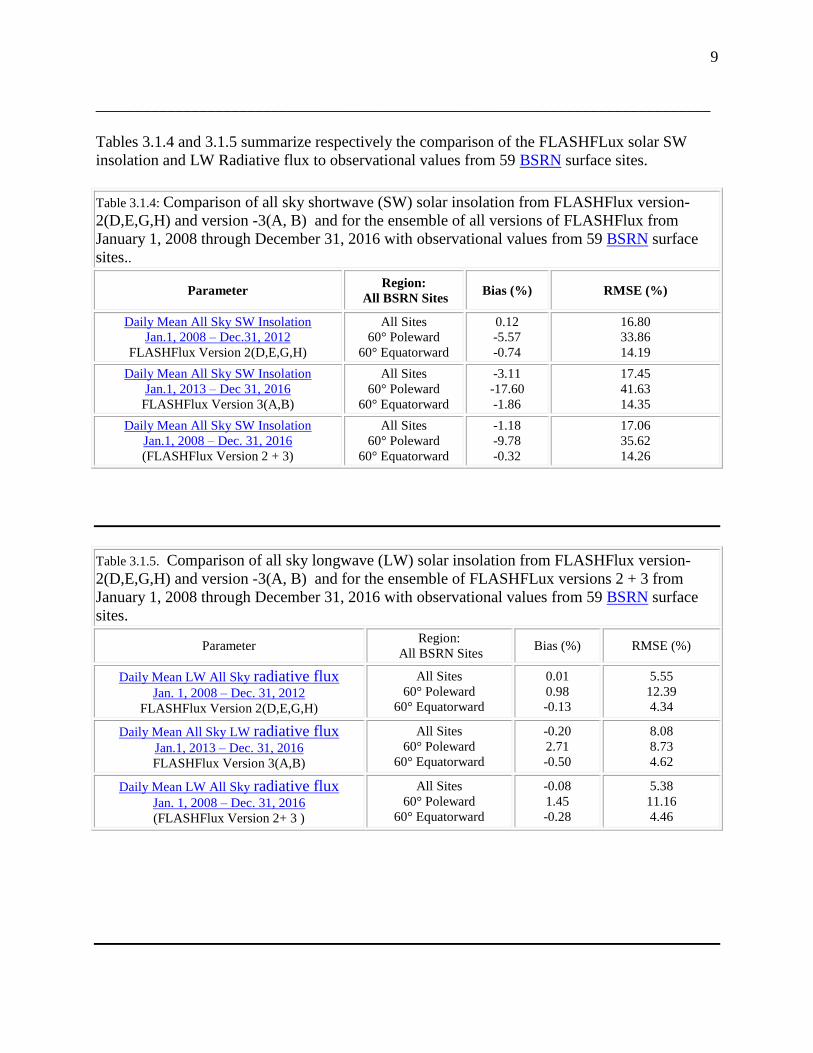
Tables 3.1.4 and 3.1.5 summarize respectively the comparison of the FLASHFLux solar SW
insolation and LW Radiative flux to observational values from 59 BSRN surface sites.
Table 3.1.4: Comparison of all sky shortwave (SW) solar insolation from FLASHFlux version-
2(D,E,G,H) and version -3(A, B) and for the ensemble of all versions of FLASHFlux from
January 1, 2008 through December 31, 2016 with observational values from 59 BSRN surface
sites..
Parameter Region:
All BSRN Sites Bias (%) RMSE (%)
Daily Mean All Sky SW Insolation
Jan.1, 2008 – Dec.31, 2012
FLASHFlux Version 2(D,E,G,H)
All Sites
60° Poleward
60° Equatorward
0.12
-5.57
-0.74
16.80
33.86
14.19
Daily Mean All Sky SW Insolation
Jan.1, 2013 – Dec 31, 2016
FLASHFlux Version 3(A,B)
All Sites
60° Poleward
60° Equatorward
-3.11
-17.60
-1.86
17.45
41.63
14.35
Daily Mean All Sky SW Insolation
Jan.1, 2008 – Dec. 31, 2016
(FLASHFlux Version 2 + 3)
All Sites
60° Poleward
60° Equatorward
-1.18
-9.78
-0.32
17.06
35.62
14.26
Table 3.1.5. Comparison of all sky longwave (LW) solar insolation from FLASHFlux version-
2(D,E,G,H) and version -3(A, B) and for the ensemble of FLASHFLux versions 2 + 3 from
January 1, 2008 through December 31, 2016 with observational values from 59 BSRN surface
sites.
Parameter Region:
All BSRN Sites Bias (%) RMSE (%)
Daily Mean LW All Sky radiative flux
Jan. 1, 2008 – Dec. 31, 2012
FLASHFlux Version 2(D,E,G,H)
All Sites
60° Poleward
60° Equatorward
0.01
0.98
-0.13
5.55
12.39
4.34
Daily Mean All Sky LW radiative flux
Jan.1, 2013 – Dec. 31, 2016
FLASHFlux Version 3(A,B)
All Sites
60° Poleward
60° Equatorward
-0.20
2.71
-0.50
8.08
8.73
4.62
Daily Mean LW All Sky radiative flux
Jan. 1, 2008 – Dec. 31, 2016
(FLASHFlux Version 2+ 3 )
All Sites
60° Poleward
60° Equatorward
-0.08
1.45
-0.28
5.38
11.16
4.46

10
Table 3.1.5. Comparison of clear sky shortwave (SW) solar insolation from FLASHFlux version-
2(D,E,G,H) and version -3(A, B) and for the ensemble of FLASHFlux versions 2+3 from
January 1, 2008 through December 31, 2016 with observational values from 27 BSRN surface
observations.
Parameter Region:
All BSRN Sites Bias (%) RMSE (%)
Daily Mean Clear Sky SW Insolation
Jan.1, 2008 – Dec 31, 2012
FLASHFlux Version 2(D,E,G,H)
All Sites
60° Poleward
60° Equatorward
-3.42
0.21
-3.65
5.44
5.36
5.45
Daily Mean Clear Sky SW Insolation
Jan.1, 2013 – Dec. 31, 2016
FLASHFlux Version 3(A,B)
All Sites
60° Poleward
60° Equatorward
-2.99
-4.53
-2.94
4.40
7.08
4.31
Daily Mean Clear Sky SW Insolation
Jan.1, 2008 – Dec. 31, 2016
FLASHFlux Version 2 + 3
All Sites
60° Poleward
60° Equatorward
-3.25
-0.89
-3.37
5.07
5.78
5.03
Table 3.1.6. Comparison of clear sky monthly mean short (SW) solar insolation from the ensemble FLASHFlux
versions -2 and -3 for the time periods January 1, 2008 – December 31, 2016 with corresponding values from
BSRN surface observations..
Parameter Region:
All BSRN Sites Bias (%) RMSE (%)
Monthly Mean All Sky SW Solar Insolation
Jan. 1, 2008 – Dec 31, 2016
(FLASHFlux Version 2 + 3 )
All Sites
60° Poleward
60° Equatorward
-1.99
-9.72
-1.07
12.64
31.70
9.04
(Return to Content)
3.2 Meteorology This section provides a summary of the estimated uncertainty associated with
the meteorological data underlying the derived parameters available through the
POWER/Buildings archive. As with the solar validations, the uncertainty estimates are based
upon comparisons with ground measurements. B more detailed description of the parameters
and the procedures used to estimate their uncertainties are given in the subsequent sections of
this document.
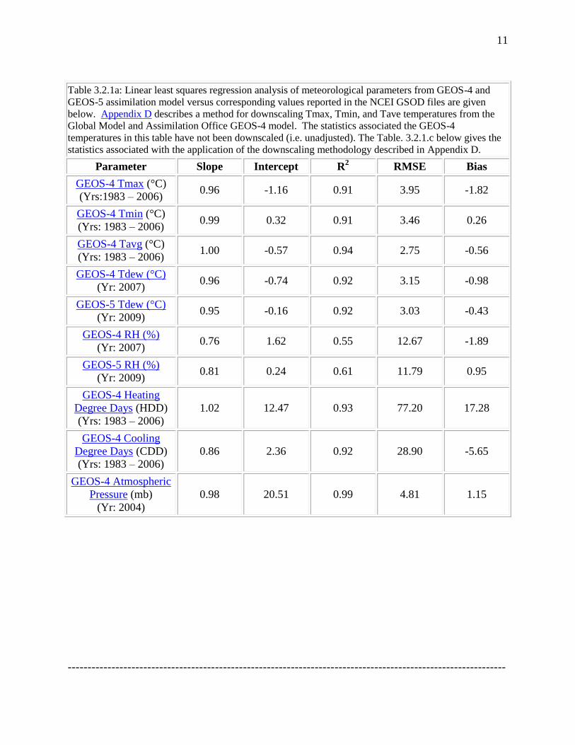
Table 3.2.1a summarizes the results of comparing GEOS-4 meteorological parameters to ground
observations reported in the National Center for Environmental Information (NCEI – formally
National Climatic Data Center) global summary of the day (GSOD) files.
Within the Sustainable Buildings archive a user can download in tabular format, the 25 year
monthly mean GEOS-4 temperatures at a given ground site as unadjusted values or as unadjusted
plus downscaled values(e.g. lapse rate and offset adjusted) based upon the elevation of the
ground site. (See Appendix D for a description of the downscaling methodology.) Table 3.2.1b
and Table 3.2.1c give, respectively, the globally monthly averaged Mean Bias Error (MBE) and
Root Mean Square Error (RMSE) for unadjusted and downscaled 2007 GEOS-4 temperatures
relative to NCEI temperatures.
11
Table 3.2.1a: Linear least squares regression analysis of meteorological parameters from GEOS-4 and
GEOS-5 assimilation model versus corresponding values reported in the NCEI GSOD files are given
below. Appendix D describes a method for downscaling Tmax, Tmin, and Tave temperatures from the
Global Model and Assimilation Office GEOS-4 model. The statistics associated the GEOS-4
temperatures in this table have not been downscaled (i.e. unadjusted). The Table. 3.2.1.c below gives the
statistics associated with the application of the downscaling methodology described in Appendix D.
Parameter Slope Intercept R2 RMSE Bias
GEOS-4 Tmax (°C)
(Yrs:1983 – 2006) 0.96 -1.16 0.91 3.95 -1.82
GEOS-4 Tmin (°C)
(Yrs: 1983 – 2006) 0.99 0.32 0.91 3.46 0.26
GEOS-4 Tavg (°C)
(Yrs: 1983 – 2006) 1.00 -0.57 0.94 2.75 -0.56
GEOS-4 Tdew (°C)
(Yr: 2007) 0.96 -0.74 0.92 3.15 -0.98
GEOS-5 Tdew (°C)
(Yr: 2009) 0.95 -0.16 0.92 3.03 -0.43
GEOS-4 RH (%)
(Yr: 2007) 0.76 1.62 0.55 12.67 -1.89
GEOS-5 RH (%)
(Yr: 2009) 0.81 0.24 0.61 11.79 0.95
GEOS-4 Heating
Degree Days (HDD)
(Yrs: 1983 – 2006)
1.02 12.47 0.93 77.20 17.28
GEOS-4 Cooling
Degree Days (CDD)
(Yrs: 1983 – 2006)
0.86 2.36 0.92 28.90 -5.65
GEOS-4 Atmospheric
Pressure (mb)
(Yr: 2004)
0.98 20.51 0.99 4.81 1.15
--------------------------------------------------------------------------------------------------------------

12
Table 3.2.1b. Globally and monthly averaged MBE and RMSE values associated with
unadjusted 2007 GEOS-4 temperatures relative to 2007 NCEI GSOD temperatures.
JAN FEB MAR APR MAY JUN JUL AUG SEP OCT NOV DEC YR Tmax
MBE -2.00 -2.11 -2.00 -1.64 -1.13 -1.15 -0.84 -1.27 -1.49 -1.85 -1.73 -1.90 -1.89
Tmax
RMSE 4.04 4.00 4.01 3.75 3.73 3.64 3.57 3.64 3.66 3.72 3.71 4.02 3.79
Tmin
MBE -0.24 -0.49 -0.23 0.19 0.56 0.49 0.66 0.61 0.81 0.76 0.50 -0.41 0.27
Tmin
RMSE 4.13 4.02 3.70 3.32 3.25 3.09 3.10 3.13 3.30 3.50 3.84 4.26 3.55
Tave
MBE -1.0 -1.15 -0.88 -0.54 -0.03 -0.06 -0.13 -0.18 -0.15 -0.43 -0.59 -1.08 -0.50
Tave
RMSE 3.20 3.18 2.92 2.62 2.66 2.54 2.55 2.50 2.51 2.56 2.91 3.41 2.80
____________________________________________________________________________
Table 3.2.1c. Globally averaged monthly MBE and RMSE associated with downscaled 2007
temperatures relative to 2007 NCEI GSOD temperatures. The GEOS-4 temperatures were downscaled using the globally and monthly averaged λ and β values given in Table B-4.
JAN FEB MAR APR MAY JUN JUL AUG SEP OCT NOV DEC YR
Tmax
MBE 0.04 -0.07 -0.04 -0.06 0.00 -0.32 -0.08 -0.30 -0.32 -0.29 0.14 0.04 -0.10
Tmax
RMSE 3.35 3.11 3.17 2.97 3.18 3.16 3.18 3.13 3.02 2.98 3.06 3.40 3.14
Tmin
MBE 1.06 0.85 0.87 0.74 0.74 0.52 0.59 0.45 0.57 0.69 0.92 0.56 0.71
Tmin
RMSE 4.11 3.87 3.54 3.13 2.99 2.83 2.86 2.87 3.01 3.26 3.71 4.12 3.36
Tave
MBE 0.52 0.33 0.48 0.28 0.27 -0.04 0.04 -0.11 0.13 0.14 0.41 0.25 0.22
Tave
RMSE 2.94 2.69 2.44 2.11 2.22 2.18 2.24 2.16 2.12 2.20 2.61 3.06 2.41
__________________________________________________________________________
Table 3.2.2a summarizes the comparison statistics for wind speeds. The monthly averaged wind
speeds have been carried over from the Goddard GEOS-4 assimilation model because newer data
sets do not provide enough information about vegetation/surface types to permit an updated
validation of the resulting wind data. The RETScreen Weather Database (RETScreen 2005) was
used to test uncertainties in the GEOS-1 wind speeds.

13
Table 3.2.2a: Estimated uncertainty for yearly averaged GEOS-1 wind speeds for the time period
July 1983 through June 1993
Parameter Method Bias RMSE
Wind Speed at 10 meters for
terrain similar to airports (m/s)
RETScreen Weather Database (documented
10-m height airport sites)
RETScreen Weather Database (unknown-
height airport sites)
-0.2
-0.0
1.3
1.3
_____________________________________________________________________________
Table 3.2.2b summarizes the comparison statistics associated with comparing wind speeds
reported in the NCEI GSOD files with estimates from the GEOS-4 and -5 assimilation models.
Table 3.2.2b: Regression parameters associated with scatter plots the daily averaged GEOS wind
speeds versus ground observations for the indicated time period.
Parameter Slope Intercept R2 RMSE Bias
GEOS-4 Wind Speed at
10 meters (m/s)
(Jan. 1, 2007 – Dec. 31, 2007)
0.55 1.62 0.42 1.76 0.011
GEOS-5 Wind Speed at
10 meters (m/s)
(Jan. 1, 2009 – Dec. 31, 209)
0.65 1.62 0.46 1.83 0.38
______________________________________________________________________________
Table 3.2.3 summarizes the regression statistics associated with scatter plots of the GPCP mean
daily precipitation and the monthly mean precipitation computed from the GPCP daily mean
values versus daily and monthly means values from ground observation reported in the NCEI
GSOD files.
Table 3.2.3: Linear least squares regression parameters associated with scatter plots of GPCP
daily and monthly 1-degree spatial precipitation estimates verses ground observations.
Parameter Slope Intercept R2 RMSE Bias
Daily 1-DD GPCP
precipitation
(mm) (Yr: 2004)
0.42 1.78 0.22 7.02 0.68
Monthly Averaged
GPCP precipitation
(mm) (Yr: 2004 )
0.60 1.43 0.46 1.72 0.68
(Return to Content)

14
4.0. Validation Methodology: The validation of the solar and meteorological parameters is based
upon comparisons of the primary POWER parameters to surface observations of the
corresponding parameters and, where possible, comparisons of the POWER parameters
calculated using the primary data to the corresponding parameters calculated using surface
observations of the corresponding primary parameters. Examples of primary parameters
comparisons include the solar and temperature values compared to surface observations; while
comparisons of relative humidity and Dew point temperature typify comparisons of calculated
parameters using the POWER primary data and the corresponding surface based observational
data.
Statistics associated with the POWER vs. surface based values are reported to provide users with
information necessary to assess the applicability of the POWER data to their particular project.
Scatter plots of the POWER parameter vs. surface based values along with the correlation and
accuracy parameters for each scatter plots are typically provided. The statistical parameters
associated with a linear least squares fit to the respective scatter plots that are reported include:
Pearson's correlation coefficient; the Bias between the mean of the respective POWER parameter
and the surface observations; the root mean square error (RMSE) calculated as the root mean
square difference between the respective POWER and observational values. Additional
parameters typically provided are the variance in the POWER and observational data and the
number of POWER:observational data pairs.
Appendix A provides the equations used to calculate the statistical validation parameters.
(Return to Content)
5.0 Global SW Solar Insolation & LW Radiative Flux: The daily mean solar radiation data for
the time period July 1, 1983 – December 31, 2007 are obtained from the NASA/Global Energy
and Water Cycle Experiment - Surface Radiation Budget Project Release 3.0 archive
(NASA/GEWEX SRB 3.0; see https://gewex-srb.larc.nasa.gov/ &
https://eosweb.larc.nasa.gov/project/srb/srb_table ).
Daily solar radiation data for the time period from January 1, 2008 to within 1-week of current
time are taken from NASA’s Fast Longwave And SHortwave Radiative Fluxes (FLASHFlux;
see https://flashflux.larc.nasa.gov/) project. Specifically, from January 1, 2008 to December 31,
2012 FLASHFLux values are taken from version -2(D, E, G, H); and from January 1, 2013 – to
within one week of real time values are taken from FLASHFlux version -3(A, B, C).
The solar data from these primary sources are produced on a global 1o latitude/ longitude grid.
For a discussion of the differences between the various versions of FLASHFlux the User is
referred to
https://eosweb.larc.nasa.gov/project/ceres/quality_summaries/FLASH_SSF_Version2.pdf and
https://eosweb.larc.nasa.gov/project/ceres/quality_summaries/FFv3_SSF_DQS.pdf
Note that care should be taken when assessing climate trends that encompass changes in the
solar source data.

15
We note here the here that the NASA/GEWEX SRB Project focuses on providing high quality
estimates of the Earth’s Top-of-atmosphere (TOA) and surface solar insolation in support of
NASA’s effort to quantify components of the Earth’s radiation budget, while the focus of the
FLASHFlux project is to provide solar data within one week of satellite observations with well
validated estimates of its accuracy.
While it is not the intent or purpose of this document to provide a detailed description of the
methodology for inferring solar data from satellite observations, a brief synopsis is provided in
the following sections.
(Return to Content)
5.1 Earth’s Radiation Budget: A central focus of the NASA’s satellite programs is to quantify
the process associated with the Earth’s energy budget. Figure 5.1.1 illustrates the major
Figure 5.1.1. The major components/processes associated with the Earth’s Energy Budget. The
values in the yellow rectangles are based upon the updated solar and thermal infrared radiation
estimates in SRB Release 3.0. (Note that all units are in W/m^2; multiplying W/m^2 by 0.024
yields kWh/day/m^2, and by 0.0864 yields MJ/day/m^2.)
components/processes associated with the Earth’s Energy Budget including updated radiative
flux components estimated from SRB Release 3.0 in the yellow boxes. These values are based on

16
a 24 year (July 1983 – Dec. 2007) annual global averaged radiative fluxes with year-to-year
annual average variability of +/- 4 W m-2
in the solar wavelengths and +/- 2 W m-2
in the thermal
infrared (longwave) flux estimates. The absolute uncertainty of these components is still the
subject of active research. For instances, the most recent satellite based measurements of the
incoming solar radiation disagree with previous measurements and indicate this value should be
closer 340.3 W m-2
providing another source of uncertainty. Other uncertainties involving the
calibration of satellite radiances, atmospheric properties of clouds, aerosols and gaseous
constituents, surface spectral albedos are all the subject of research within the GEWEX SRB
project.
(Return to Content)
5.2 GEWEX SRB 3.0 SW and LW Radiative Transfer Models: The surface solar shortwave
(SW) insolation and the longwave (LW) radiative flux available from the POWER data archives
are based upon observational data from a variety of satellites. The basic observational data is the
amount of radiation emerging from the earth’s atmosphere (see Fig. 5.1.1). The amount of
radiation measured is affected by atmospheric absorption, emission and scattering processes as
illustrated in Fig. 5.1.1. Radiative transfer models (i.e. the GEWEX Longwave and Shortwave
Algorithms, and the Langley Parameterized Longwave and Shortwave Algorithms) describing
the processes depicted in Fig. 5.1.1 provide the bases for estimating the SW insolation and LW
radiative flux.
The GEWEX Longwave (LW) Algorithm uses the Fu et al., (1997, JAS, Vol. 54, 2799-2812)
Thermal Infrared radiative transfer code with cloud and surface parameters requiring cloud,
atmospheric profile information, and surface properties. Inputs to the algorithm were obtained
from the following sources: The ISCCP DX cloud pixels were separated into categories of high,
middle and low where middle and low clouds could be composed of ice or water. Cloud fractions
and cloud optical depths were determined within these categories. Cloud particle sizes were
assumed and cloud physical thicknesses were also designed based upon information from
literature. Random overlap is used between the high, middle and low layers to better approximate
under cast conditions.
The GEWEX Shortwave (SW) Algorithm uses a modified method of Pinker and Laszlo (1992)
to solve the radiative transfer equation and provide the GEWEX SRB 3.0 estimates of surface
SW solar insolation. This method involves the use of a radiative transfer model, along with
cloud parameters derived from the DX data of the International Satellite Cloud Climatology
Project (ISCCP; Rossow and Schiffer, 1999, BAMS, 80, 2261-2287) and temperature and
moisture profiles taken from 4-D data assimilation products provided by the Data Assimilation
Office at NASA GSFC and produced with the Goddard Earth Observing System model version 4
(GEOS-4) and ozone column amounts from satellite measurements. Three satellite visible
radiances are used: the instantaneous clear sky radiance, the instantaneous cloudy sky radiance,
and the clear sky composite radiance, which is a representation of a recent dark background
value. The observed satellite radiances are converted into broadband shortwave TOA albedos,
using Angular Distribution Models from the Earth Radiation Budget Experiment (Smith et al.,
1986). The spectral shape of the surface albedo is fixed by surface type. The radiative transfer
model (through the use of lookup tables) is then used to find the absolute value of the surface

17
albedo which produces a TOA upward flux which matches the TOA flux from the conversion of
the clear-sky composite radiance. For this step, a first guess of the aerosol amount is used. The
aerosol used for this purpose was derived from six years (2000-2005) of daily output from the
MATCH chemical transport model (Rasch et al.,1997). A climatology of aerosol optical depth
was developed for each of the twelve months by collecting the daily data for each grid cell, and
finding the mode of the frequency distribution. The mode was used rather than the average so as
to provide a typical background value of the aerosol, rather than an average which includes much
higher episodic outbreak values. The surface albedo now being fixed, the aerosol optical depth is
chosen within the radiative transfer model to produce a TOA flux which matches the TOA Flux
from the conversion of the instantaneous clear sky radiance. Similarly the cloud optical depth is
chosen to match the TOA flux implied from the instantaneous cloudy sky radiance. With all
parameters now fixed, the model outputs a range of parameters including surface and TOA
fluxes. All NASA/GEWEX SRB 3.0 parameters are output on a 10 by 1
0 global grid at 3-hourly
temporal resolution for each day of the month.
(Return to Content)
5.3. FLASHFlux SW and LW Radiative Transfer Model: The Fast Longwave and SHortwave
Flux (FLASHFlux) project is based upon the algorithms developed for analysis and data
collected by the Clouds and the Earth's Radiant Energy System (CERES -
http://ceres.larc.nasa.gov/ ) project. CERES is currently producing world-class climate data
products derived from measurements taken aboard NASA's Terra and Aqua spacecrafts. While
of exceptional fidelity, CERES data products require a extensive calibration checks and
validation to assure quality and verify accuracy and precision. The result is that CERES data are
typically released more than six months after acquisition of the initial measurements. For climate
studies, such delays are of little consequence especially considering the improved quality of the
released data products. There are, however, many uses for the CERES data products on a near
real-time basis such as those referred to within the POWER project. To meet those needs,
FLASHFlux has greatly sped up the processing by using the earliest stream of data coming from
CERES instruments and using fast radiation algorithms to produce results within one week of
satellite observations. This results in the loss of climate-quality accuracy due to bypassing of
some calibration checks, and some gaps in the earliest stream of satellite data.
For speedy retrieval of surface SW insolation, FLASHFlux uses the SW Model B that is also
used in CERES processing. This model is named the Langley Parameterized SW Algorithm
(LPSA) and described in detail in Gupta et al. (2001). It consists of physical parameterizations
which account for the attenuation of solar radiation in simple terms separately for clear
atmosphere and clouds. Surface insolation, Fsd, is computed as
5.3.1 Fsd = Ftoa Ta Tc ,
where Ftoa is the corresponding TOA insolation, Ta is the transmittance of the clear atmosphere,
and Tc is the transmittance of the clouds. Both FLASHFlux and CERES rely on similar input
data sets from the meteorological products and Moderate Resolution Imaging Spectroradiometer
(MODIS). However, it is important to note that even though the FLASHFlux endeavor intends
to incorporate the latest input data sets and improvements into its algorithms, there are no plans
to reprocess the FLASHFlux data products once these modifications are in place. Thus, in
contrast to the CERES data products, the FLASHFlux data products are not to be considered of
18
climate quality. Users seeking climate quality should instead use the CERES data products. In
the following section estimates of the accuracy of the GEWEX SRB 3.0 and FLASHFlux solar
data are provided.
The LW Radiative fluxes are produced via the Langley Parameterized Longwave algorithm
(LPLA). Detailed descriptions of this algorithm can be found in Gupta et al. (1992) - J. Appl.
Meteor., 31, 1361-1367; Gupta (1989) - J. Climate, 2, 305-320, and Wilber et al. (1999) -
NASA/TP-1999-209362.
(https://ntrs.nasa.gov/archive/nasa/casi.ntrs.nasa.gov/20020022720.pdfere )
(Return to Content)
5.4. Validation of SW Solar Insolation & LW Radiative Flux (All Sky Conditions): The
GEWEX SRB and FLASHFlux radiative transfer models described in the preceding sections
produce estimates of the SW solar insolation and LW Radiative flux on a 1o latitude, longitude
global grid. The validation of the SRB and FLASHFlux data is based on this 1o data.
Validation of both the SRB and FLASHFlux solar data is based upon comparisons against
research quality observations from the Baseline Surface Radiation Network (BSRN; Ohmura et
al., 1998). Figure 5.4.1 shows the location of 47 ground stations within the BSRN network used
for the GEWEX SRB 3.0 validation. Figure 5.4.2 shows the location of 59 ground stations
within the BSRN network used for the FLASHFlux validation.
The validation time period for the SRB 3.0 shortwave (SW) insolation and longwave (LW)
Radiative flux values is from July 1, 1983 – December 31, 2007
Daily solar radiation data for the time period from January 1, 2008 to within 1-week of current
time are taken from NASA’s Fast Longwave And SHortwave Radiative Fluxes (FLASHFlux;
see https://flashflux.larc.nasa.gov/) project. Specifically, from January 1, 2008 to December 31,
2012 FLASHFLux values are taken from version -2(D, E, G, H); and from January 1, 2013 – to
within one week of real time values are taken from FLASHFlux version -3(A, B, C).
For a discussion of the differences between the various versions of FLASHFlux the User is
referred to
https://eosweb.larc.nasa.gov/project/ceres/quality_summaries/FLASH_SSF_Version2.pdf and
https://eosweb.larc.nasa.gov/project/ceres/quality_summaries/FFv3_SSF_DQS.pdf .
Care should be taken when assessing climate trends that encompass changes in the solar source
data.
See Section 4.0, Validation Methodology, for additional description of the validation
methodology.

19
Figure 5.4.1. Location of ground stations in the Baseline Surface Radiation Network (BSRN)
used for the validation of the SRB-3.0 SW solar insolation & LW radiative flux.
Figure 5.4.2. Location of ground stations in the Baseline Surface Radiation Network (BSRN)
used to validation of the FLASHFlux SW solar insolation & LW radiative flux.
(Return to Content)

20
5.4.1. SRB 3.0 Daily Mean SW Solar Insolation (All Sky Conditions); Scatter plots of the
total (i.e. diffuse plus direct) surface insolation observed at the BSRN ground sites versus the
corresponding insolation values from the SRB release 3.0 archive are shown in Figure 5.4.1 for
daily mean SW values. The comparison covers the time period January 1, 1992, the earliest that
data from BSRN is available, through December 31, 2007. The statistics given in the upper left
box are for all BSRN sites (Globally), those located 60-degree poleward, and for those located
60-degree equatorward. The Bias is the difference between the mean (μ) of the respective solar
radiation values for SRB and BSRN. RMS is the root mean square difference between the
respective SRB and BSRN values. The correlation coefficient between the SRB and BSRN
values is given by ρ, the variance in the SRB values is given by σ, and N is number of
SRB:BSRN month pairs for each latitude region.
Figure 5.4.1.1. Scatter plot of daily total surface SW solar radiation observed at BSRN ground
sites over the years 1992 - 2007 versus daily values from the GEWEX/SRB Release 3.0 archive
for all sky conditions. (Note that the solar radiation unit is kWh/day/m^2; multiplying
kWh/day/m^2 by 3.6 yields MJ/day/m^2, and by 41.67 yields W/m^2.)

21
Table 5.4.1.1 gives the statistics resulting from comparisons of the monthly averages of the daily
values of SRB and the corresponding BSRN values for each month of the year during the time
period from January 1, 1992 through December 31, 2007. ,
Table 5.4.1.1. Statistics associated with the comparison of the monthly averages of the SRB (V3.0) and BSRN daily mean shortwave insolation from 1992-01 to 2007-12.
Month Bias
(kWh/ m2 da)
RMS (kWh/ m2
da) ρ
μ BSRN
(kWh/ m2 da)
Bias (%)
RMS (%)
N
01 -0.096 0.8664 0.9449 3.1296 -3.09 27.68 9657
02 -0.0912 0.8232 0.9175 3.4536 -2.67 23.86 8781
03 -0.1152 0.8208 0.9207 3.9912 -2.87 20.59 10045
04 -0.0768 0.8064 0.9420 4.5144 -1.72 17.84 9947
05 -0.0648 0.8352 0.9489 5.0112 -1.29 16.67 10354
06 -0.0336 0.8952 0.9486 5.1408 -0.63 17.44 10217
07 0 0.84 0.9499 5.1264 0.01 16.38 10751
08 -0.036 0.7944 0.9428 4.7016 -0.78 16.88 10579
09 -0.0384 0.744 0.9351 4.248 -0.91 17.54 10149
10 -0.0768 0.8376 0.9171 3.6504 -2.09 22.92 10544
11 -0.1032 0.912 0.9273 3.1992 -3.21 28.52 10170
12 -0.1272 0.9384 0.9455 3.1368 -4.05 29.89 10291
Overall -0.072 0.8448 0.9447 4.1256 -1.72 20.47 121485 * As of 2011-06-16.
(Return to Content)
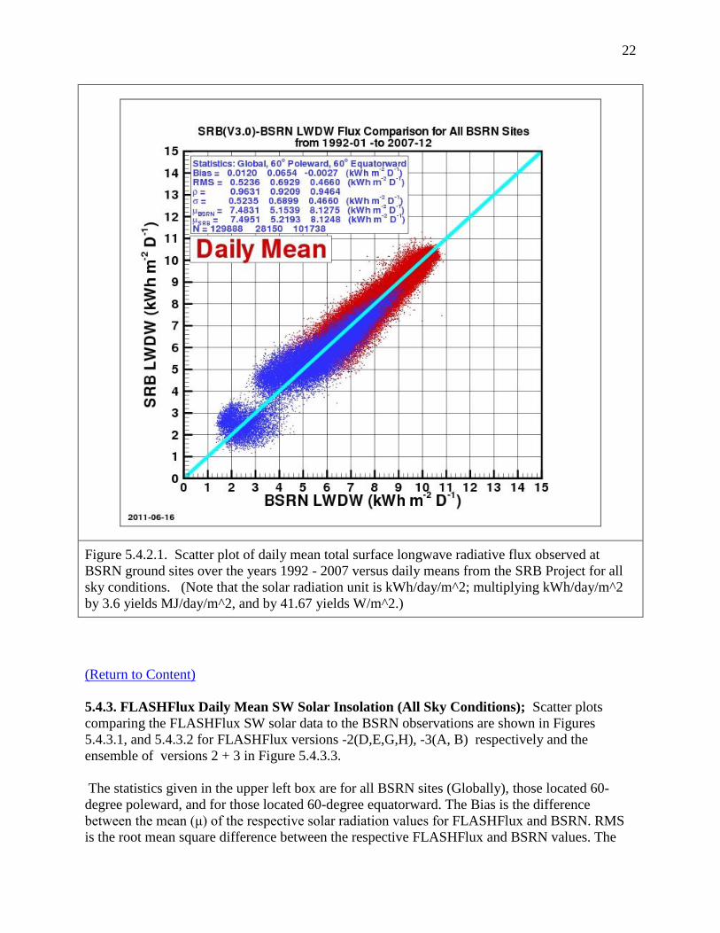
5.4.2. SRB 3.0 Daily Mean LW Radiative Fluxes (All Sky Conditions): The longwave (LW)
radiative fluxes in the time period from July 1983 – December 2007 were taken from release 3 of
the NASA/GEWEX Surface Radiation Budget project (GEWEX SRB 3.0 - https://gewex-
srb.larc.nasa.gov/ & https://eosweb.larc.nasa.gov/project/srb/srb_table . A scatter plot of the
daily mean LW surface insolation observed at the BSRN ground sites versus corresponding
values from the SRB release 3.0 archive is shown in Figure 5.4.2.1. The comparisons cover the
time period January 1, 1992, the earliest that data from BSRN is available, through December
31, 2007. The statistics given in the upper left box are for all BSRN sites (Globally), those
located 60-degree poleward, and for those located 60-degree equatorward. The Bias is the
difference between the mean (μ) of the respective solar radiation values for SRB and BSRN.
RMS is the root mean square difference between the respective SRB and BSRN values. The
correlation coefficient between the SRB and BSRN values is given by ρ, the variance in the SRB
values is given by σ, and N is number of SRB:BSRN month pairs for each latitude region.
22
Figure 5.4.2.1. Scatter plot of daily mean total surface longwave radiative flux observed at
BSRN ground sites over the years 1992 - 2007 versus daily means from the SRB Project for all
sky conditions. (Note that the solar radiation unit is kWh/day/m^2; multiplying kWh/day/m^2
by 3.6 yields MJ/day/m^2, and by 41.67 yields W/m^2.)
(Return to Content)
5.4.3. FLASHFlux Daily Mean SW Solar Insolation (All Sky Conditions); Scatter plots
comparing the FLASHFlux SW solar data to the BSRN observations are shown in Figures
5.4.3.1, and 5.4.3.2 for FLASHFlux versions -2(D,E,G,H), -3(A, B) respectively and the
ensemble of versions 2 + 3 in Figure 5.4.3.3.
The statistics given in the upper left box are for all BSRN sites (Globally), those located 60-
degree poleward, and for those located 60-degree equatorward. The Bias is the difference
between the mean (μ) of the respective solar radiation values for FLASHFlux and BSRN. RMS
is the root mean square difference between the respective FLASHFlux and BSRN values. The

23
correlation coefficient between the FLASHFlux and BSRN values is given by ρ, the variance in
the FLASHFlux values is given by σ, and N is number of FLASHFlux:BSRN pairs for each
latitude region.
Figure 5.4.3.1 Scatter plot of daily total surface solar shortwave radiation observed at BSRN
ground sites over the years January 1, 2008 – December 31, 2012 versus daily values from the
FLASHFlux version-2(D, E, G, H). (Note that the solar radiation unit is kWh/day/m^2;
multiplying kWh/day/m^2 by 3.6 yields MJ/day/m^2, and by 41.67 yields W/m^2.)
(Return to Content)

24
Figure 5.4.3.2. Scatter plot of daily total surface solar shortwave radiation observed at BSRN
ground sites over the years January 1, 2013 – December 31, 2016 versus daily values from the
FLASHFlux version-3(A, B). (Note that the solar radiation unit is kWh/day/m^2; multiplying
kWh/day/m^2 by 3.6 yields MJ/day/m^2, and by 41.67 yields W/m^2.)
(Return to Content)

25
Figure 5.4.3.3. . Scatter plot of daily total surface solar shortwave radiation observed at BSRN
ground sites over the years January 1, 2008 – December 31, 2016 versus daily values from the
FLASHFlux versions 2+3. (Note that the solar radiation unit is kWh/day/m^2; multiplying
kWh/day/m^2 by 3.6 yields MJ/day/m^2, and by 41.67 yields W/m^2.)
(Return to Content)
5.4.4. FLASHFlux Daily Mean LW Radiative Flux (All Sky Conditions): Scatter plots
comparing the FLASHFlux LW solar data to the BSRN observations are shown in Figures
5.4.4.1, and 5.4.4.2 for FLASHFlux versions -2(D,E,G,G,H) and, versions -3(A.B) respectively
and the ensemble of version 2 + 3 in Figure 5.4.4.3. The statistics given in the upper left box are
for all BSRN sites (Globally), those located 60-degree poleward, and for those located 60-degree
equatorward. The Bias is the difference between the mean (μ) of the respective solar radiation
values for FLASHFlux and BSRN. RMS is the root mean square difference between the
respective FLASHFlux and BSRN values. The correlation coefficient between the FLASHFlux
and BSRN values is given by ρ, the variance in the FLASHFlux values is given by σ, and N is
number of FLASHFlux:BSRN pairs for each latitude region.
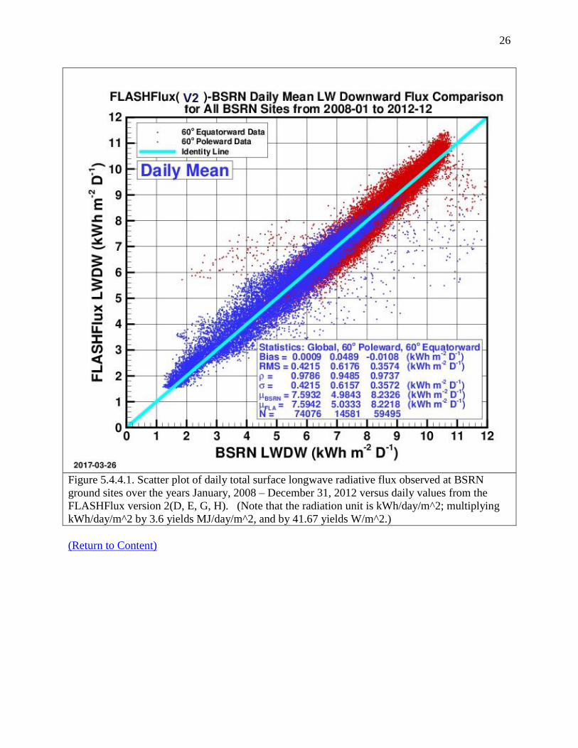
26
Figure 5.4.4.1. Scatter plot of daily total surface longwave radiative flux observed at BSRN
ground sites over the years January, 2008 – December 31, 2012 versus daily values from the
FLASHFlux version 2(D, E, G, H). (Note that the radiation unit is kWh/day/m^2; multiplying
kWh/day/m^2 by 3.6 yields MJ/day/m^2, and by 41.67 yields W/m^2.)
(Return to Content)

27
Figure 5.4.4.2. Scatter plot of daily total surface longwave radiative flux observed at BSRN
ground sites over the years January 1, 2013 – December 31, 2016 versus daily values from the
FLASHFlux versions 3(A,B). (Note that the radiation unit is kWh/day/m^2; multiplying
kWh/day/m^2 by 3.6 yields MJ/day/m^2, and by 41.67 yields W/m^2.)
(Return to Content)

28
Figure 5.4.4.3. Scatter plot of daily total surface longwave radiative flux observed at BSRN
ground sites over the years January 1, 2008 – December 31, 2016 versus daily values from the
FLASHFlux versions 2+3. (Note that the radiation unit is kWh/day/m^2; multiplying
kWh/day/m^2 by 3.6 yields MJ/day/m^2, and by 41.67 yields W/m^2.)
(Return to Content)

29
5.4.5. Monthly 3-Hourly Mean SRB Shortwave Insolation (All sky Conditions): Figure
5.4.5.1 shows the scatter plot comparing the monthly averaged 3-hourly values of SRB v3.0 to
the monthly averaged values from BSRN observations, The statistics given in the upper left box
are for all BSRN sites (Globally), those located 60-degree poleward, and for those located 60-
degree equatorward. The Bias is the difference between the mean (μ) of the respective solar
radiation values for SRB and BSRN. RMS is the root mean square difference between the
respective SRB and BSRN values. The correlation coefficient between the SRB and BSRN
values is given by ρ, the variance in the FLASHFlux values is given by σ, and N is number of
SRB:BSRN pairs for each latitude region.
Figure 5.4.5.1. Scatter plot of 3-hourly monthly mean of total surface solar radiation observed at
BSRN ground sites over the years 1992 – 2007 versus 3-hourly monthly mean values from the
GEWEX SRB 3.0 archive for all sky conditions. (Note that the radiation unit is kWh/day/m^2;
multiplying kWh/day/m^2 by 3.6 yields MJ/day/m^2, and by 41.67 yields W/m^2.)
(Return to Content)

30
5.4.6 Monthly Mean Shortwave Insolation (All sky Conditions): Figure 5.4.6.1 shows the
scatter plot comparing the monthly mean values of SRB v3.0 to the corresponding values from
BSRN observations. The statistics given in the upper left box are for all BSRN sites (Globally),
those located 60-degree poleward, and for those located 60-degree equatorward.
Figure 5.4.6.1. Scatter plot of monthly total surface solar radiation observed at BSRN ground
sites over the years 1992 – 2007 versus monthly values from the GEWEX/SRB Release 3.0
archive for all sky conditions. The daily values illustrated in figure 5.4.2.1 are used to calculate
the monthly averages. The bias differs from the daily value due to differences in sampling
requirements. (Note that the radiation unit is kWh/day/m^2; multiplying kWh/day/m^2 by 3.6
yields MJ/day/m^2, and by 41.67 yields W/m^2.)
The Bias is the difference between the mean (μ) of the respective solar radiation values for SRB
and BSRN. RMS is the root mean square difference between the respective SRB and BSRN

31
values. The correlation coefficient between the SRB and BSRN values is given by ρ, the
variance in the SRB values is given by σ, and N is number of SRB:BSRN pairs for each latitude
region.
(Return to Content)
5.4.7 FLASHFlux Monthly Mean SW Insolation (All Sky Conditions): Figure 5.4.7.1 shows
the scatter plot comparing the monthly mean values of FLASHFlux 2H+3A+3B to the
corresponding values from BSRN observations. The statistics given in the upper left box are for
all BSRN sites (Globally), those located 60-degree poleward, and for those located 60-degree
Figure 5.4.7.1. Scatter plot of monthly mean total surface solar radiation observed at BSRN
ground sites over the years 2008 – 2016 versus monthly means from the FLASHFlux version
2 +3 for all sky conditions. The daily values illustrated in figure 5.4.2.2 are used to calculate the
monthly averages. (Note that the radiation unit is kWh/day/m^2; multiplying kWh/day/m^2 by
3.6 yields MJ/day/m^2, and by 41.67 yields W/m^2.)

32
equatorward. The Bias is the difference between the mean (μ) of the respective solar radiation
values for SRB and BSRN. RMS is the root mean square difference between the respective SRB
and BSRN values. The correlation coefficient between the SRB and BSRN values is given by ρ,
the variance in the FLASHFlux values is given by σ, and N is number of SRB:BSRN pairs for
each latitude region.
(Return to Content)
5.5 Validation of SW Solar Insolation (Clear Sky Conditions): For these comparisons it was
necessary to ensure that the ground observations and the satellite derived solar radiation values
are for equivalent clear sky conditions. Fortunately, observational data from a number of BSRN
ground sites (see Figure 5.5.1) and the satellite observational data provide information related to
cloud cover for each observational period. Cloud parameters from the NASA ISCCP were used
to infer the solar radiation in the GEWEX SRB 3.0 archive. Parameters within the ISCCP data
provide a measure of the clearness for each satellite observation used in the SRB-inversion
algorithms. Similarly, observations from upward viewing cameras at the 27 BSRN sites shown
in Figure 5.5.1 provided a measure of cloud cover for each ground observational period.
Figure 5.5.1. Location of ground stations in the Baseline Surface Radiation Network (BSRN)
with upward viewing cameras.

33
The clear sky comparison data shown in this section utilized ground cameras and the ISCCP data
to match clearness conditions. In particular, the comparison shown below uses clearness criteria
defined such that clouds in the field of view of the upward viewing camera and the field of view
from the ISCCP satellites must both be less than 10%.
(Return to Content)
5.5.1 SRB 3.0 Daily Mean SW Solar Insolation (Clear Sky Conditions): A scatter plot of the
total (i.e. diffuse plus direct) surface insolation observed at the BSRN ground sites versus the
corresponding insolation values from the SRB release 3.0 archive is shown in Figure 5.5.1.1 for
daily mean SW for clear sky conditions. The comparison covers the time period January 1, 1992,
the earliest that data from BSRN is available, through December 31, 2007. The statistics given
in the upper left box are for all BSRN sites (Globally), those located 60-degree poleward, and for
those located 60-degree equatorward. The Bias is the difference between the mean (μ) of the
respective solar radiation values for SRB and BSRN. RMS is the root mean square difference
between the respective SRB and BSRN values. The correlation coefficient between the SRB and
BSRN values is given by ρ, the variance in the SRB values is given by σ, and N is number of
SRB:BSRN month pairs for each latitude region.

34
Figure 5.5.1.1. Scatter plot of the daily total clear sky radiation derived from observations at
BSRN ground sites vs. daily total values from GEWEX SRB 3.0. Clear sky conditions are
defined for less than 10% cloud cover in field-of-view of both the upward viewing ground and
downward viewing satellite cameras. (Note that solar radiation is in W/m^2; multiplying
W/m^2 by 0.024 yield KWh/m^2/day and by 0.0864 yields MJ/day/m^2.)
(Return to Content)
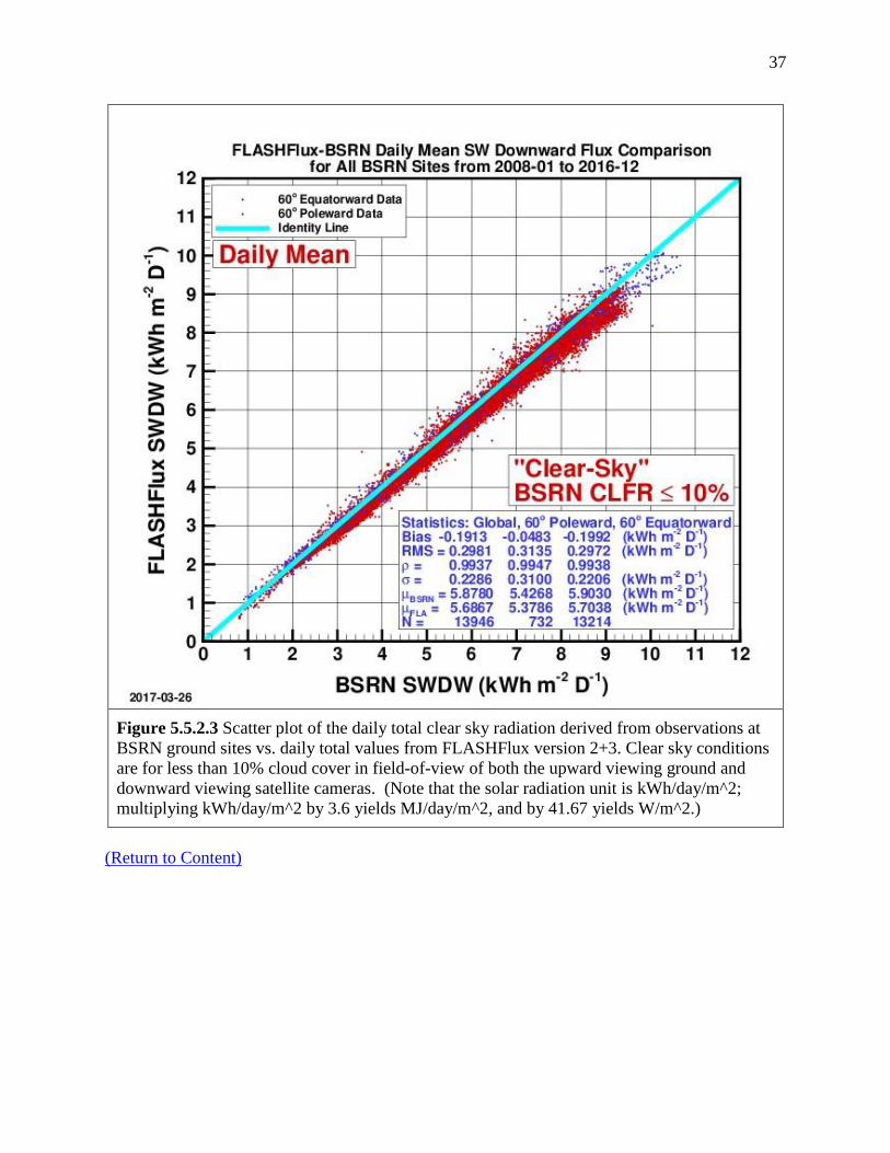
5.5.2 FLASHFLux Daily Mean SW Solar Insolation (Clear Sky Conditions): Scatter plots
comparing the FLASHFlux SW clear sky solar insolation to the BSRN observations are shown in
Figures 5.5.2.1 and 5. 5.2.2 for FLASHFlux versions -2(D, E, G, H) and version-3(A, B) and the
ensemble of versions 2 + 3 in Figure 5.5.2.3. The statistics given in the upper left box are for all
BSRN sites (Globally), those located 60-degree poleward, and for those located 60-degree
equatorward. The Bias is the difference between the mean (μ) of the respective solar radiation
values for FLASHFlux and BSRN. RMS is the root mean square difference between the

35
respective FLASHFlux and BSRN values. The correlation coefficient between the FLASHFlux
and BSRN values is given by ρ, the variance in the FLASHFlux values is given by σ, and N is
number of FLASHFlux:BSRN pairs for each latitude region.
Figure 5.5.2.1 Scatter plot of the daily total clear sky radiation derived from observations at
BSRN ground sites vs. daily total values from FLASHFlux version 2(D,E,G, H). Clear sky
conditions are for less than 10% cloud cover in field-of-view of both the upward viewing ground
and downward viewing satellite cameras. (Note that the solar radiation unit is kWh/day/m^2;
multiplying kWh/day/m^2 by 3.6 yields MJ/day/m^2, and by 41.67 yields W/m^2.)

36
Figure 5.5.2.2 Scatter plot of the daily total clear sky radiation derived from observations at
BSRN ground sites vs. daily total values from FLASHFlux version 3(A, B) for the time period
January 1, 2013 – December 31, 2016 . Clear sky conditions are for less than 10% cloud cover in
field-of-view of both the upward viewing ground and downward viewing satellite cameras.
(Note that the solar radiation unit is kWh/day/m^2; multiplying kWh/day/m^2 by 3.6 yields
MJ/day/m^2, and by 41.67 yields W/m^2.)
37
Figure 5.5.2.3 Scatter plot of the daily total clear sky radiation derived from observations at
BSRN ground sites vs. daily total values from FLASHFlux version 2+3. Clear sky conditions
are for less than 10% cloud cover in field-of-view of both the upward viewing ground and
downward viewing satellite cameras. (Note that the solar radiation unit is kWh/day/m^2;
multiplying kWh/day/m^2 by 3.6 yields MJ/day/m^2, and by 41.67 yields W/m^2.)
(Return to Content)

38
5.5.3 SRB Monthly Mean Shortwave Insolation (Clear Sky Conditions); Figure 5.5.3.1is a
scatter plot of the monthly mean of SRB 3.0 SW insolation versus the corresponding monthly
mean based upon BSRN observation. The monthly mean for the SRB and BSRN values are for
clear sky conditions where clear sky is defined as conditions for which the cloud cover in the
field of view of satellite and surface observations is less that 10%. Results of the comparison are
given in the upper right hand box. The Bias is the difference between the mean (µ) of the
respective solar radiation values for SRB and BSRN; RMS is the root mean square difference
between the respective SRB and BSRN values; the correlation coefficient between the SRB and
BSRN values is given by ρ; the variance in the SRB values is given by σ; and N is number of
SRB:BSRN daily pairs.
Figure 5.5.3.1. Scatter plot of the monthly averaged clear sky total radiation derived from
observations at BSRN ground sites vs. monthly averaged values from GEWEX SRB 3.0. Clear
sky conditions are for less than 10% cloud cover in field-of-view of both the upward viewing
ground and downward viewing satellite cameras. (Note that the solar radiation unit is
kWh/day/m^2; multiplying kWh/day/m^2 by 3.6 yields MJ/day/m^2, and by 41.67 yields
W/m^2.)
(Return to Content)

39
6. Diffuse and Direct Normal Radiation on a Horizontal Surface: The all sky (i.e. all cloud
conditions) total global solar radiation from the SRB archive discussed in Section 5 is the sum of
diffuse and direct normal radiation. However, estimates of all sky horizontal diffuse, (HAll
)Diff,
and direct normal radiation, (HAll
)DNR are often needed parameters for the design of hardware
such as solar panels, solar concentrator size, day lighting, as well as agricultural and hydrology
applications. From an observational perspective, (HAll
)Diff at the surface of the earth is that
radiation remaining with (HAll
)DNR from the sun's beam blocked by a shadow band or tracking
disk. (HAll
)Diff is typically measured using a sun tracking pyrheliometer with a shadow band or
disk to block the direct normal radiation from the sun. Similarly, from an observational
perspective, (HAll
)DNR is the amount of solar radiation from the direction of the sun, and is
typically measured using a pyrheliometer tracking the sun throughout the day.
(Return to Content)
6.1. POWER Method: Measurements of (HAll
)Diff and (HAll
)DNR are difficult to make and
consequently are generally only available at high quality observational sites such as those in the
BSRN network or the . In order to use the global estimates of the total surface solar radiation,
HAll
from SRB Release 3.0 to provide estimates of (HAll
)Diff and (HAll
)DNR, a set of polynomial
equations have been developed relating the ratio of [(HAll
)Diff]/[ HAll
] to the clearness index KT =
[HAll
]/[HTOA
] using ground based observations from the BSRN network. These relationships
were developed by employing observations from the BSRN network to extend the methods
employed by RETScreen (RETScreen, 2005) to estimate (HAll
)DNR .
In this section we outline the techniques for estimating the [(HAll
)Diff] and [(HAll
)DNR] from the
solar insolation values available in SRB Release 3.0. In the following section results of
comparative studies with ground site observations are presented, which serve to validate the
resulting [(HAll
)Diff] and [(HAll
)DNR] and provide a measure of the overall accuracy of our global
results.
All Sky Monthly Averaged Diffuse Radiation [(HAll
)Diff]: As just noted, measurements of
(HAll
)Diff, (HAll
)DNR, and HAll
are made at the ground stations in the BSRN network. These
observational data were used to develop the set of polynomial equations given below relating the
ratio [(HAll
)Diff]/[ HAll
] to the clearness index KT = [HAll
]/[HTOA
]. We note that the top of
atmosphere solar radiation, HTOA
, is known from satellite observations.
For latitudes between 0 and 45 degrees North and South: [(H
All)Diff]/[ H
All] =
0.96268 - 1.45200*KT + 0.27365*KT^2 + (0.04279*KT^3 + 0.000246*SSHA +
0.001189*NHSA
For latitudes between 45 and 90 degrees North and South: If SSHA = 0 - 81.4 deg:
[(HAll
)Diff]/[ HAll
] =1.441-(3.6839*KT)+(6.4927*KT^2)-(4.147*KT^3)+(0.0008*SSHA)-
(0.008175*NHSA)

40
If SSHA = 81.4 - 100 deg:
[(HAll
)Diff]/[ HAll
] =1.6821-(2.5866*KT)+(2.373*KT^2)-(0.5294*KT^3)-(0.00277*SSHA)-
(0.004233*NHSA)
If SSHA = 100 - 125 deg:
[(HAll
)Diff]/[ HAll
] =0.3498+(3.8035*KT)-(11.765*KT^2)+(9.1748*KT^3)+(0.001575*SSHA)-
(0.002837*NHSA)
If SSHA = 125 - 150 deg:
[(HAll
)Diff]/[ HAll
] =1.6586-(4.412*KT)+(5.8*KT^2)-(3.1223*KT^3)+(0.000144*SSHA)-
(0.000829*NHSA)
If SSHA = 150 - 180 deg:
[(HAll
)Diff]/[ HAll
] = 0.6563-(2.893*KT)+(4.594*KT^2)-(3.23*KT^3)+(0.004*SSHA)-
(0.0023*NHSA)
where:
KT = [HAll
]/[HTOA
]
SSHA = sunset hour angle in degrees
NHSA = noon solar angle from the horizon in degrees
The above set of polynomial equations relate the ratio of monthly averaged horizontal diffuse
radiation for all sky conditions to the monthly averaged total solar radiation for all sky conditions
{ [(HAll
)Diff]/[HAll
] } to the clearness index KT = [HAll
]/[HTOA
].
All Sky Monthly Averaged Direct Normal Radiation:
[(HAll
)DNR] = ([ HAll
] - [(HAll
)Diff] )/ COS(THMT)
where:
THMT is the solar zenith angle at the mid-time between sunrise and solar noon (Gupta, et
al. 2001) for the “monthly average day” (Klein 1977).
COS(THMT) = f + g [(g - f)/ 2g]1/2
HAll
= Total of direct beam solar radiation and diffuse atmospheric radiation falling on a
horizontal surface at the earth's surface
(HAll
)Diff = diffuse atmospheric radiation falling on a horizontal surface at the earth's
surface
f = sin(latitude) sin(solar declination)
g = cos(latitude) cos(solar declination)
If the Sunset Hour Angle = 180 degrees, then COS(THMT) = f.
(Return to Content)

41
6.2. Validation: Figures 6.2.1 and 6.2.2 show respectively scatter plots for the monthly mean
diffuse and monthly mean direct normal radiation for all sky conditions computed from
measured values at the BSRN sites (designated as BSRN SWDF and BSRN SWDN) versus the
corresponding GEWEX SRB 3.0 values (designated as SRB SWDF and SRB SWDN) derived
from the expression discussed above. Figures 6.2.3 and 6.2.4 show similar scatter plots for clear
sky conditions.
6.2.1. Monthly Mean Diffuse (All Sky Conditions)
Figure 6.2.1. Scatter plot of the all sky monthly mean horizontal diffuse radiation calculated
from BSRN observations and the corresponding radiation derived from GEWEX SRB-Release
3.0 data (Jan. 1992 - Dec. 2007). (Note that solar radiation is in KWh/day/m^2; multiplying
KWh/day/m^2 by 41.67 yields W/m^2, and by 3.6 yields MJ/day/m^2.)
Correlation and accuracy parameters are given in the legend boxes. Note that for the all sky
condition the correlation and accuracy parameters are given for all sites (e.g. Global), for the
BSRN sites regions above 600 latitude, north and south, (i.e. 60
0 poleward) and for BSRN sites
below 600 latitude, north and south (60
0 equatorward). However, because of the scarcity of clear

42
sky values only the global region is used for the statistics in Figures 6.2.3 and 6.2.4. The Bias is
the difference between the mean (µ) of the respective solar radiation values for SRB and BSRN.
RMS is the root mean square difference between the respective SRB and BSRN values. The
correlation coefficient between the SRB and BSRN values is given by ρ, the variance in the SRB
values is given by σ, and N is number of SRB:BSRN pairs for each latitude region.
(Return to Content)
6.2.2. Monthly Mean Direct Normal (All Sly Conditions)
Figure 6.2.2. Scatter plot of the monthly mean all sky direct normal radiation determined from
BSRN ground observations and the corresponding radiation derived from SRB-Release 3.0 data
(Jan. 1992 – Dec. 2007). (Note that solar radiation is in KWh/day/m^2; multiplying
KWh/day/m^2 by 41.67 yields W/m^2, and by 3.6 yields MJ/day/m^2.)

43
(Return to Content)
6.2.3. Monthly Mean Diffuse (Clear Sky Conditions)
Figure 6.2.3. Scatter plot of the monthly mean clear sky diffuse radiation on a horizontal surface
determined from BSRN ground observations and the corresponding radiation derived from SRB-
Release 3.0 data (Jan. 1992 – Dec. 2007). (Note that solar radiation is in KWh/day/m^2;
multiplying KWh/day/m^2 by 41.67 yields W/m^2, and by 3.6 yields MJ/day/m^2.)
(Return to Content)
44
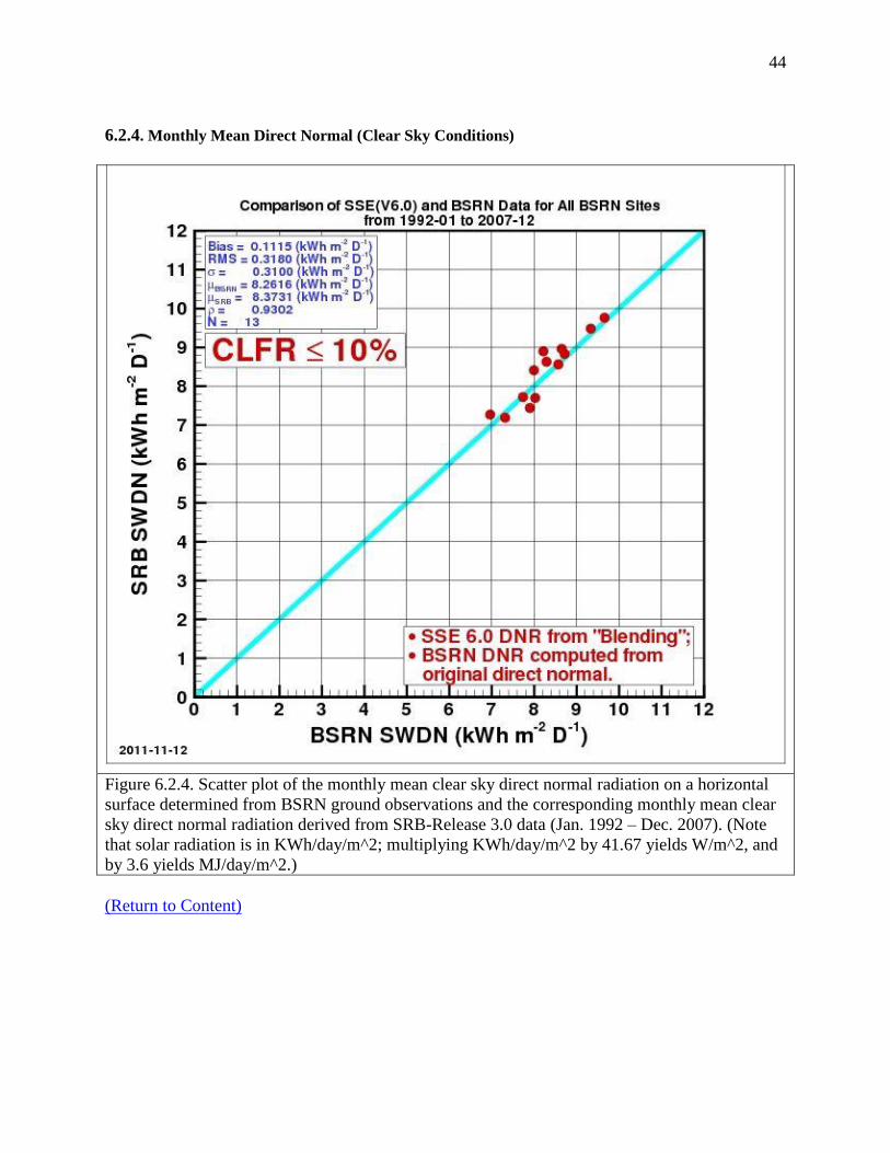
6.2.4. Monthly Mean Direct Normal (Clear Sky Conditions)
Figure 6.2.4. Scatter plot of the monthly mean clear sky direct normal radiation on a horizontal
surface determined from BSRN ground observations and the corresponding monthly mean clear
sky direct normal radiation derived from SRB-Release 3.0 data (Jan. 1992 – Dec. 2007). (Note
that solar radiation is in KWh/day/m^2; multiplying KWh/day/m^2 by 41.67 yields W/m^2, and
by 3.6 yields MJ/day/m^2.)
(Return to Content)

45
7. Insolation On a Tilted Surface The calculation of the insolation impinging on a tilted surface
basically follows the method employed by RETScreen (RETScreen 2005). The major difference
is that the diffuse radiation is derived from the equations described in Section V above which
contain slight modifications on the RETSCreen approach.
7.1. Overview of RETScreen Method: In this section we briefly outline the RETScreen
method. The RETScreen method uses the “monthly average day” hourly calculation procedures
where the equations developed by Collares-Pereira and Rabl (1979) and Liu and Jordan (1960)
are used respectively for the “monthly average day” hourly insolation and the “monthly average
day” hourly diffuse radiation.
Hourly Total and Diffuse Insolation on a Horizontal Surface: We first describe the method of
estimating the hourly horizontal surface insolation (Hh) and horizontal diffuse (Hdh) for daylight
hours between 30 minutes after sunrise to 30 minutes before sunset during the “monthly average
day”. The “monthly average day” is the day in the month whose declination is closest to the
average declination for that month (Klein 1977). Table 7.1.1 lists the date and average
declination for each month.
Table 7.1.1. List of the day in the month whose solar declination is closest to the average
declination for that month
Month Date in month Declination Month Date in month Declination
January 17 -20.9 July 17 21.2
February 16 -13.0 August 16 13.5
March 16 -2.4 September 15 2.2
April 15 9.4 October 15 -9.6
May 15 18.8 November 14 -18.9
June 11 23.1 December 10 -23.0
Hh = rtH
Hdh = rdHd
where:
H is the monthly average horizontal surface insolation from the SRB 3.0 data set.
Hd is the monthly average horizontal diffuse from the method described in section V.
rt = (/24)*(A + Bcos)*[(cos - coss)/(sins - s coss)]
(Collares-Pereira and Rabl; 1979)
rd = (/24)*[(cos - coss)/(sins - s coss)] (Liu and Jordan; 1960)
where:
A = 0.409 + 0.5016 sin[s - (/3)]
B = 0.6609 - 0.4767 sin[s - (/3)]
where:

46
= solar hour angle for each daylight hour relative to solar noon between sunrise plus 30
minutes and sunset minus 30 minutes. The sun is displaced 15o from the local meridian
for each hour from local solar noon.
s = sunset hour angle
s = cos-1
[-tan (solar declination)*tan(latitude)], (+ = west relative to solar noon)
where:
solar declination = 23.45*sin[6.303*{(284 + n)/365}]
n = day number of year, 1 = January 1
Hourly total radiation on a tilted surface: Next, we describe the method of estimating hourly
total radiation on a tilted surface (Hth) as outlined in the RETScreen tilted surface method. The
equation, in general terms, is:
Hth = solar beam component + sky diffuse component + surface/sky reflectance component
The solution is as follows:
coszh = cos(latitude) cos(solar declination) cos + sin(latitude) sin(solar declination)
cosh = coszh cosh + (1 - coszh) (1 - cosh) (cos(sh - h))
where:
h = hourly slope of the PV array relative to a horizontal surface. h is constant for fixed
panels or panels in a vertical- axis tracking system. h = z for panels in a two-axis
tracking system. Values for other types of tracking systems are given in Braun and
Mitchell (1983).
sh = sin-1
[(sin cos(solar declination))/sinzh]
= hourly solar azimuth angle; angle between the line of sight of the Sun into the
horizontal surface and the local meridian. Azimuth is zero facing the equator,
positive west, and negative east.
h = hourly surface azimuth of the tilted surface; angle between the projection of the
normal to the surface into the horizontal surface and the local meridian. Azimuth is
zero facing the equator, positive west, and negative east. h is constant for fixed
surfaces. h = sh for both vertical- and two-axis tracking systems. See Braun and
Mitchell (1983) for other types of tracking systems.
Hth = (Hh - Hdh)(cosh/coszh) + Hdh [(1+cosh)/2] + Hh*s[(1-cosh)/2]
where:
s = surface reflectance or albedo is assumed to be 0.2 if temperature is above 0oC or 0.7 if
temperature is below -5oC. Linear interpolation is used for temperatures between these values.
47
Finally, the monthly average tilted surface insolation (Ht) is estimated by summing hourly values
of Hth over the “monthly average day”. It was recognized that such a procedure would be less
accurate than using quality “day-by-day” site measurements, but RETScreen validation studies
indicate that the “monthly average day” hourly calculation procedures give tilted surface results
ranging within 3.9% to 8.9% of “day-by-day” hourly methods.
It should be emphasized that the optimum tilt angle of a tilted solar panel at a given latitude and
longitude is not simply based on solar geometry and the site latitude. The solar geometry relative
to the Sun slowly changes over the period of a month because of the tilted axis of the Earth.
There is also a small change in the distance from the Sun to Earth over the month because of the
elliptical Earth orbit around the Sun. The distance variation may cause a change in the trend of
the weather at the latitude/longitude location of the tilted solar panel. The weather trend over the
month may be toward either clearer or more cloudy skies over that month for that particular year.
Cloudy- diffuse or clear-sky direct normal radiation may vary from year to year. As a result, the
hourly calculations of tilted solar panel performance for a monthly-average day are made for all
1-degree cells over the globe for a 22-year period. Both the tilt angles and insolation values
should be considered as average values over that 22-year period.
Table 7.2 illustrates the tilted radiation that is provide for a user selected latitude = 45.9N and a
latitude = 116.21W. The monthly averaged total (i.e. diffuse + direct normal) solar insolation
incident on a surface at the selected coordinates is provide for a horizontal panel (tilt angle = 0°),
and at angles relative to the horizontal equal to the latitude, and latitude ± 15 ° and for the
surface facing south (S) , north (N), east (E) , and West (W) [e.g. Total 30o (S)].

48
Table 7.2 Example of the insolation of a surface at the user selected latitude, longitude
coordinates. The total insolation (i.e. diffuse + direct normal) is given as climatological monthly
averages for a horizontal surface (i.e. Total 00) and for surfaces tilted at angles equal to the
latitude + 15o relative to the horizontal and for surfaces facing south (S), east (E), north (N), and
west (W).
(Return to Content)
7.2 Validation of Monthly Mean Insolation on a Tilted Surface: In this section results from
three approaches for validation of the monthly mean insolation on a tilted surface are presented.
The first involves comparison of the insolation on a tilted surface derived fron the GEWEX/SRB
3.0 and FLASHFlux insolation and and RETScreen formulation. The remaining two approaches
provide more definitive validation statistics in that the surface insolation on a tilted surface is
compared to measured tilted surface insolation values and to values that were derived from
measurements of the diffuse and direct normal components of solar flux on tilted surfaces at
BSRN sites.
(Return to Content)

49
7.2.1. GEWEX SRB 3.0 vs RETScreen. Table 7.2.1.1 summarizes the agreement between the
POWER and RETScreen formulation in terms of the Bias and RMSE between the two methods,
and the parameters (i.e. slope, intercept, and R^2) characterizing the linear least square fit to the
RETScreen values (x-axis) to GEWEX SRB 3.0 values (y-axis) when both the RETScreen and
POWER methods have the same horizontal insolation as inputs.
Table 7.2.1.1. Summary results from a comparison of the insolation on a tilted surface as estimated using the
RETSCreen and POWER methods. Both approaches start with the GEWEX SRB 3.0 monthly averaged
insolation on a horizontal surface.
Recall that the major difference between the two methods involves the determination of the
diffuse radiation, and note that the results from the two methods are in good agreement.
(Return to Content)
7.2.2 GEWEX SRB 3.0 vs Direct Measurements of Tilt Insolation. Figure 7.2.2.1 show the
time series of the monthly mean solar insolation derived from measurements and the
corresponding values from GEWEX SRB 3.0.

50
(a)
(b)
Figure 7.2.2.1 Monthly time series of solar insolation measure on a horizontal (a) and tilted (b)
surface at the University of Oregon Solar Radiation Monitoring Laboratory Chaney, WA station,
and corresponding insolation from RETScreen and BEWEX SRB 3.0. (Note that solar radiation
is in KWh/day/m^2; multiplying KWh/day/m^2 by 41.67 yields W/m^2, and by 3.6 yields
MJ/day/m^2.)

51
Figure 7.2.2.1a gives the measured and GEWEX SRB 3.0 solar insolation on a horizontal surface
and Figure 7.2.2.1.b gives the measured and GEWEX SRB 3.0 values on a South facing surface
tilted at 45o. The measured values were taken from the University of Oregon Solar Radiation
Monitoring Laboratory archive (http://solardat.uoregon.edu/index.html) for Chaney, WA. For
comparison the RETScreen values have also been included. We note that the monthly averages
have been computed from GEWEX SRB 3.0 data over the 1992 – 2005 time period.
(Return to Content)
7.2.3. GEWEX SRB 3.0 vs BSRN Based Tilt Insolation. Solar insolation measurements at the
most of the ground sites in the BSRN include the diffuse and direct normal components as well
as a direct measurement of the global, or total, insolation on a horizontal surface. These
measurements are typically made with at 1-, 2-, 3- or 5-minute intervals throughout the day. The
diffuse and direct normal measurements, coupled with the solar zenith angle, provide the
necessary components to estimate solar insolation on a tilted surface as outlined below.
For any given BSRN site, consider a 3-D coordinate system with the origin at the BSRN site, X-
axis pointing eastward, Y-axis northward, and Z-axis upward. For any given instant
corresponding to a BSRN record, the unit vector pointing to the Sun is {sin(Z)cos[(/2)-A]i,
sin(Z)sin[(/2)-A]j, cos(Z)k}, and the unit vector along the normal of the titled surface is [0i, -
sin(T)j, cos(T)k] for Northern Hemisphere, and [0i, sin(T)j, cos(T)k] for Southern Hemisphere,
where Z is the solar zenith angle, A is the azimuth angle of the Sun, and T is the tilt angle of the
tilted surface. And the direct flux on the tilted surface is the direct normal flux times the dot
product of the aforementioned two unit vectors which is -sin(Z)cos(A)sin(T)+cos(Z)cos(T) for
Northern Hemisphere and sin(Z)cos(A)sin(T)+cos(Z)cos(T) for Southern Hemisphere. If the dot
product of the two unit vectors is less than zero, which means the Sun is behind the tilted surface,
the direct flux on the tilted surface is set to zero. After this conversion, the 3-hourly, daily and
monthly means of the direct component on the tilted surface can then be derived, and the diffuse
component can be similarly derived. The sum of the direct and diffuse components is the total
flux on the tilted surface.
Figure 7.2.3.1 is a scatter plot of the climatological monthly mean insolation on a tilted surface
derived from the BSRN measurements of the diffuse and direct normal components versus the
corresponding GEWEX SRB 3.0 tilt radiation values.

52
Figure 7.2.3.1Scatter plot of the climatological monthly mean insolation on a tilted surface derived from
the BSRN measurements of the diffuse and direct normal components versus the corresponding GEWEX-
SRB 3.0 tilt radiation values for all sky conditions. (Note that solar radiation is in KWh/day/m^2;
multiplying KWh/day/m^2 by 41.67 yields W/m^2, and by 3.6 yields MJ/day/m^2.)
(Return to Content)

53
8. Meteorological Parameters: Table 2.1 lists the meteorological parameters provided through
the 1-degree Sustainable Buildings archive, their temporal coverage and source. The global
distribution of meteorological parameters in the POWER/Sustainable Buildings archive are
obtained from NASA’s Global Model and Assimilation Office (GMAO), Goddard Earth
Observing System global assimilation models version 4 (GEOS-4:
http://gmao.gsfc.nasa.gov/systems/geos4/) and version-5 (GEOS-5:
http://gmao.gsfc.nasa.gov/products/ ) . The relative humidity is a calculated parameter based
upon pressure, temperature and specific humidity, all parameters obtained from the assimilation
models. Dew/frost point temperatures are calculated values based upon the relative humidity and
air temperature which is obtained from the assimilation model. Precipitation is obtained from
the Global Precipitation Climate Project. Monthly mean winds are from the GOES-2
assimilation model, and daily winds are from the GEOS-4 assimilation model over the time
period January 1, 1983 – December 31, 2007 and from the GEOS-5 models over the time period
January 1, 2008 – to within several days of current time. In this section the results associated
with testing /validating each parameter against ground site observation is discussed.
(Return to Content)
8.1. Assessment of Assimilation Modeled Temperatures: As noted above all meteorological
parameters, except precipitation, are based directly or indirectly (i.e. calculated) on the GMAO
assimilation models. The meteorological parameters emerging from the GMAO assimilation
models are estimated via “An atmospheric analysis performed within a data assimilation context
[that] seeks to combine in some “optimal” fashion the information from irregularly distributed
atmospheric observations with a model state obtained from a forecast initialized from a previous
analysis.” (Bloom, et al., 2005). The model seeks to assimilate and optimize observational data
and model estimates of atmospheric variables. Types of observations used in the analysis include
(1) land surface observations of surface pressure; (2) ocean surface observations of sea level
pressure and winds; (3) sea level winds inferred from backscatter returns from space-borne
radars; (4) conventional upper-air data from rawinsondes (e.g., height, temperature, wind and
moisture); (5) additional sources of upper-air data include drop sondes, pilot balloons, and
aircraft winds; and (6) remotely sensed information from satellites (e.g., height and moisture
profiles, total perceptible water, and single level cloud motion vector winds obtained from
geostationary satellite images). Emerging from the analysis are 3-hourly global estimates of the
vertical distribution of a range of atmospheric parameters. The assimilation model products are
bi-linearly interpolated to a 10 by 1
0 grid.
In addition to the analysis reported by the NASA’s Global Model and Assimilation Office
(GMAO) (Bloom, et al. 2005), the POWER project initiated a study focused on determining the
accuracy of the GEOS-4 meteorological parameters in terms of the applications within the
POWER project. In particular, the GEOS-4 temperatures (minimum, maximum and daily
averaged air and dew point), relative humidity, and surface pressure have been explicitly
compared to global data obtained from the National Center for Environmental Information
(NCEI – formally National Climatic Data Center- http://www.ncdc.noaa.gov/oa/ncdc.html )
global “Summary of the Day” (GSOD) files, and to observations from other high quality
networks such as the Surface Radiation (SURFRAD -
http://www.srrb.noaa.gov/surfrad/index.html), Atmospheric Radiation Measurement (ARM -

54
http://www.arm.gov/), as well as observations from automated weather data networks such as the
High Plains Regional Climate Center (HPRCC - http://www.hprcc.unl.edu/index.php).
In this section we will focus primarily on the analysis of the GEOS-4 daily maximum and
minimum temperatures, and the daily mean temperature using observations reported in the NCEI
- GSOD files, with only summary comments regarding results from the other observational
networks noted above. The GEOS-4 re-analysis model outputs meteorological parameters at 3-
hourly increments (e.g. 0, 3, 6, 9, 12, 15, 18, and 21 Z) on a global 1- deg by 1.25-deg grid at 50
pressure levels. The 1-deg by 1.25-deg grid is bi-linearly interpolated to a 1-deg by 1-deg grid to
match the GEWEX/SRB 3.0 solar radiation values. The local daily maximum (Tmax) and
minimum (Tmin) temperature, and the local daily mean (Tave) temperature at 2 meters above the
surface were obtained from the GEOS-4 3-hourly data. The Sustainable Buildings GEOS-4
meteorological data spans the time period from January 1, 1983 - through December 2007;
comparative analysis discussed here is based upon observational data from January 1, 1983
through December 31, 2006.
The observational data reported in the NCEI GSOD files are hourly observations from globally
distributed ground stations with observations typically beginning at 0Z. For the analysis reported
herein, the daily Tmin, Tmax and Tave were derived from the hourly observations filtered by an
“85%” selection criteria applied to the observations reported for each station. Namely, only data
from NCEI stations reporting 85% or greater of the possible 1-hourly observations per day and
85% or greater of the possible days per month were used to determine the daily Tmin, Tmax, and
Tave included in comparisons with the GEOS-4 derived data. Figure 8.1.1 illustrates the global
distribution of the surface stations remaining in the NCEI data files for 1983 and 2004 after
applying our 85% selection criteria. Note that the number of stations more than doubled from
1983 (e.g. 1104 stations) to 2004 (e.g. 2704 stations), and that majority of the stations are located
in the northern hemisphere.
Unless specifically noted otherwise, all GEOS-4 air temperatures represent the average value on
a 1o x 1
o latitude, longitude grid cell at an elevation of 2 m above the earth’s surface and NCEI
values are ground observations at an elevation of 2 meters above the earth’s surface. Scatter
plots of Tave, Tmax, and Tmin derived from ground observations in the NCEI files versus
GEOS-4 values for the years 1987 and 2004 are shown in Figure 8.1.2. These plots illustrate the
agreement typically observed for all the years 1983 through 2006. In the upper left corner of
each figure are the parameters for the linear least squares regression fit to theses data, along with
the mean Bias and RMSE between the GEOS-4 and NCEI observations. The mean Bias and
RMSE are given as:
Bias = ∑j{∑i{[(Tij)GEOS4 - (Ti
j)NCEI]}}/N
RMSE = {∑j{∑i{[(Tij)GEOS4 - (Ti
j)NCEI ]
2/N}}}
1/2,
where, ∑i is summation over all days meeting the 85% selection criteria, ∑j indicates the sum
over all stations, (Tij)NCEI is the temperature on day i for station j, and (Ti
j)GEOS4 is the GEOS-4
temperature corresponding to the overlapping GEOS-4 1-degree cell for day i and station j, and
N is the number of matching pairs of NCEI and GEOS-4 values.

55
Figure 8.1.1: Top (a) and bottom (b) figures show distribution of NCEI stations meeting 85%
selection criteria for 1987 and 2004, respectively.
For the year 1987, 1139 stations passed our 85% selection criteria yielding 415,645 matching
pairs on NCEI/GEOS-4 values; for 2004, 2697 stations passed yielding 987,451 matching pairs
of NCEI/GEOS-4 temperature values. The color bar along the right side of the scatter plot
provides a measure of the distribution of the NCEI/GEOS-4 temperature pairs. For example, in
Figure 8.1.2, each data point shown in dark blue represents a 1-degree cell with 1 to 765
matching temperature pairs, and all of the 1-degree cells shown in dark blue contain 15.15% of
the total number of ground site points. Likewise, the darkest orange color represents 1-degree

56
Figure 8.1.2. Top (a), middle (b) and bottom (c) figures show the scatter plot of ground site
observations versus GEOS-4 values of Tmax, Tmin, and Tave for the years 1987 and 2004. The
color bar in each figure indicates the number and percentage of ground stations that are included
within each color range.

57
cells for which there are from 6120 to 6885 matching temperature pairs, and taken as a group all
of the 1-degree cells represented by orange contain 10.61% of the total number of matching
ground site points. Thus, for the data shown in Figure 8.1.2a, approximately 85% of matching
temperature pairs (i.e. excluding the data represented by the dark blue color) is “tightly” grouped
along the 1:1 correlation line.
In general, the scatter plots shown in Figure 8.1.2, and indeed for all the years from 1983 through
2006, exhibit good agreements between the GEOS-4 data and ground observations. Notice
however that for both the 1987 and 2004 data, on a global basis, the GEOS-4 Tmax values are
cooler than the ground values (e.g. bias = -1.9 C in 1987 and -1.8 C in 2004); the GEOS-4 Tmin
values are warmer (e.g. bias = 0.4 o C in 1987 and 0.2
o C in 2004); and that GEOS-4 Tave values
are cooler (e.g. bias = -0.5 o C in 1987, and -0.6
o C in 2004. Similar trends in the respective
yearly averaged biases between GEOS-4 and NCEI observations were noted for each year from
1983 – 2006 (see Table 8.1.1 below). The ensemble average for the years 1983 – 2006 yields a
GEOS-4 Tmax which is 1.82o C cooler than observed at NCEI ground Sites, a Tmin about 0.27
o
C warmer, and a Tave about 0.55o C cooler. Similar trends are also observed for measurements
from other meteorological networks. For example, using the US National Weather Service
Cooperative Observer Program (COOP) observations, White, et al (2008) found the mean values
of GEOS-4 Tmax, Tmin, and Tave to be respectively 2.4o C cooler, Tmin 1.1
o C warmer, and 0.7
o C cooler that the COOP values.
Table 8.1.1 Global year-by-year comparison of daily Tmax, Tmin, and Tave: NCEI GSOD
values vs GEOS-4 temperatures
The average of the least square fit along with the average RMSE and Bias values given in Table
8.1.1 are taken as representative of the agreement expected between GEOS-4 temperatures and
ground site measurements.
Further analysis, described in Appendix D, shows that one factor contributing to the temperature
biases between the assimilation model estimates and ground site observations is the difference in
the elevation of the reanalysis grid cell and the ground site. Appendix D describes a

58
downscaling methodology based upon a statistical calibration of the assimilation temperatures
relative to ground site observations. The resulting downscaling parameters (i.e. lapse rate and
offset values) can be regionally and/or seasonally used to downscale the model temperatures
yielding estimates of local temperatures with reduced biases relative to ground site observations.
Application of the downscaling procedure described in Appendix D is currently implemented in
the Sustainable Buildings Archive to provide adjusted 25–year monthly mean Tmax, Tmin, and
Tave temperatures based upon a user's input of the ground site elevation. As an example of
downscaling, Table B.5 and Table B.6 in Appendix D give, respectively, the global monthly
averaged Mean Bias Error (MBE) and Root Mean Square Error (RMSE) for unadjusted and
downscaled 2007 GEOS-4 temperatures relative to NCEI temperatures.
Assessment of GEOS-5 Temperatures: An initial assessment of the GEOS-5 temperatures
follows the methodology described above for the GEOS-4 temperatures. Results from the
assessment, which included 4.172 globally distributed ground stations reporting observations in
the NCEI GSOD files for the year 2009, are given in Table 8.1.2.
Table 8.1.3. Summary of statistics for a global comparison of the uncorrected GEOS-5 daily
temperatures to ground observations reported by 4172 stations in the NCEI GSOD files during
2009
Parameter Bias RMSE Slope Intercept R^2 Daily Values
Tave -0.98 3.15 0.96 -0.74 0.92 1,214,462
Tmax -1.07 3.62 0.97 -0.58 0.93 1,518,601
Tmin 0.84 3.68 0.97 1.05 0.91 1,519,039
(Return to Content)
8. 2. Relative Humidity: The relative humidity (RH) values in the POWER archives are
calculated from pressure (Pa in kPa), dry bulb temperature (Ta in °C), and mixing ratio (e.g.
specific humidity, q in kg/kg), parameters that are available in the NASA’s assimilation model.
The following is a summary of the expressions used to calculate RH. The units are indicated in
square brackets.
From Iribarne and Godson (1981) a fundamental definition of the Relative Humidity (Eq. 83, pg
75):
(8.2.1) RH = (ea/esat) × 100%
where
ea = the water vapor pressure and
esat the saturation water vapor pressure at the ambient temperature Ta.
The 100% has been added to cast RH in terms of percent.

59
Since water vapor and dry air (a mixture of inert gases) can be treated as ideal gases, it can be
shown that (Iribarne and Godson, pg 74, Eq. 76; Note that the symbol, r, use in Eq. 76 for the
mixing ratio has been replaced by “w” and the factor of “10” has been added to convert the units
to hPa.)
(8.2.2) ea = (10×Pa×w)/(ε + w) [hPa]
where w is the mixing ratio define as the ratio of mass of water to dry air and
(8.2.3)
where R’ and Rv are the dry and water vapor gas constants respectively (note that there is no
exact consensus for the gas constants past 3 significant digits, therefore the value of the ratio is
kept to 3 significant digits). The mixing ratio is related to specific humidity by the relation (Jupp
2003, pg.37):
(8.2.4) w = q / (1-q) [kg/kg]
Combining (8.2.2) and (8.2.4) leads to the following expression for e in terms of q:
(8.2.5) ea = q×10×Pa/[ε + q× (1- ε)] [hPa]
An eighth-order polynomial fit (Flatau, et. al. 1992) to measurements of vapor pressure over ice
and over water provides an expression to calculate the saturated water vapor pressure over ice
and over water. The eight-order fit for esatw is given by
(8.2.6) ewsat = A1w + A2w×(Ta) + …+ A(n-1)w×(Ta)n
and
(8.2.7) eisat = A1i + A2i×(Ta) + …+ A(n-1)i× (Ta)n ,
Where
ewsat = saturated vapor pressure over water in [hPa = mb]
eisat = saturated vapor pressure over ice [hPa=mb]
Ta is the ambient dry bulb temperature in oC.
Table 8.2.1 gives the coefficients for esat over water and over ice and the temperature range over
which the coefficient are applicable.

60
Table 8.1.1. Coefficients of the eight-order polynomial fit (Taken from Flatau, et. al. 1992
Table 4.) to measurements of saturated vapor pressure measurements,
Coefficients for esat over water valid over the
temperature range -85 oC to +70
oC
Coefficients for esat over ice valid over the
temperature range -90 oC to 0
oC
A1w = 6.11583699
A2w = 0.444606896
A3w = 0.143177157E-1
A4w = 0.264224321E-3
A5w = 0.299291081E-5
A6w = 0.203154182E-7
A7w = 0.702620698E-10
A8w = 0.379534310E-13
A9w = -0.321582393E-15
A1i = 6.09868993
A2i = 0.499320233
A3i = 0.184672631E-1
A4i = 0.402737184E-3
A5i = 0.565392987E-5
A6i = 0.521693933E-7
A7i = 0.307839583E-9
A8i = 0.105758160E-11
A9i = 0.161444444E-14
Note that only the relative humidity over water is calculated and provided in the
POWER/Sustainable Buildings Archive consistent with the values reported by the National
Weather Service..
GEOS-4 Relative Humidity: Table 8.2.2 Summarizes the comparison statistics for the relative
humidity based upon GEOS-4 q, P, T values vs. ground observations reported in the 2007 NCEI
GSOD files.
(Note that for the comparison statistics in Tables 8.2.1 and –8.2 the RH was calculated
using a different approximation for calculating RH, however the percentage differences in
the RH values was typically less the 10%.)
Table 8.2.2. Summary of statistics for a global comparison of the daily mean relative humidity
based upon GEOS-4 q, P, T values to ground observations reported in the NCEI GSOD files
during 2007.
Bias RMSE Slope Intercept R^2 Daily Values
-1.89 12.67 0.76 1.62 0.55 1,214,462
GEOS-5 Relative Humidity: Table 8.2.3 Summarizes the comparison statistics for the relative
humidity values based upon GEOS-5 q, P, and T vs. ground observations reported in the 2009
NCEI GSOD files.
Table 8.2.3. Summary of statistics for a global comparison of the daily mean relative humidity
based upon GEOS-5 q, P, T values to ground observations reported in the NCEI GSOD files
during 2009.
Bias RMSE Slope Intercept R^2 Daily Values
-0.95 11.79 0.81 0.24 0.61 1,428,047
(Return to Content)

61
8.3. Dew/Frost Point Temperatures: The daily dew and frost point temperatures are calculated
from the relative humidity and temperature. Note that as per http://www.ofcm.gov/fmh-1/pdf/J-
CH10.pdf section 10.5.1 of the “Federal Meteorological handbook N0. 1 – Surface Weather
observations and Reports, September 2005”, the “Dew point shall be calculated with respect to
water at all temperatures.” Accordingly, the nomenclature that will be used herein is to
designate dew/frost point temperatures based upon the RH over water as Tdpt. The Tdpt is
calculated using the expression (2003, Encyclopedia of Agricultural, Food, and Biological
Engineering, Page 189, Edited by Dennis R. Heldman; Online ISBN 0-8247-0937-3).
(8.3.1) Tdpt = Ta – [(14.55 + 0.114 × Ta) × RH1
+ ((2.5 + 0.007 × Ta) × RH1)3
+ ((15.9 + 0.117 × Ta) × RH114
)]
Where
Ta = Ambient air temperature
and
RH1 = 1.0 – RH/100.
The RH value over water is calculated, as described in Section 8.2.
The following tables give the statistics associated with comparing the dew/frost point
temperatures based upon GEOS-4 RH and Ta values (Table 8.3.1) and GEOS-5 RH and Ta
values (Table 8.3.2).
(Note that for the comparison statistics in Tables 8.3.1 and –C.2 the RH was calculated
using a different approximation for calculating RH, however the differences in the dew
point temperatures ranging from approximately -50C to 40C was less than 1C. )
Table 8.3.1. Summary of statistics for a global comparison of the GEOS-4 daily mean dew point
to ground observations reported by 3410 station in the NCEI GSOD files during 2007.
Bias RMSE Slope Intercept R^2 Daily Values
-0.98 3.15 0.96 -0.74 0.92 1,214,462
Table 8.3.2. Summary of statistics for a global comparison of the GEOS-5 daily mean dew point
to ground observations reported by 4172 stations the NCEI GSOD files during 2009.
Bias RMSE Slope Intercept R^2 Daily Values
-0.43 3.03 0.95 -0.16 0.92 1,428,047
(Return to Content)

62
8.4. Precipitation: The precipitation data in POWER/Building archive has been obtained from
version 2.1 Global Precipitation Climate Project (GPCP – 1DD) Satellite-Gauge Product
http://precip.gsfc.nasa.gov). Version 2.1, is a global 1°x1° daily accumulation based upon
combination of observations from multiple platforms described at
http://precip.gsfc.nasa.gov/gpcp_v2.1_comb_new.html and synopsized below as:
Version 2.1 Global Precipitation Climate Project Satellite-Gauge Product
1. Special Sensor/Microwave Imager (SSM/I; 0.5°x0.5° by orbit, GPROF algorithm)
provides fractional occurrence of precipitation, and
2. GPCP Version 2 Satellite-Gauge (SG) combination (2.5°x2.5° monthly) data provides
monthly accumulation of precipitation as a “scaling constraint” that is applied to the
algorithms use to estimate precipitation values from :
a. geosynchronous-orbit IR (geo-IR) Tb histograms (1°x1° grid in the band 40°N-40°S,
3-hourly),
b. low-orbit IR (leo-IR) GOES Precipitation Index (GPI; same time/space grid as geo-
IR),
c. TIROS Operational Vertical Sounder (TOVS; 1°x1° on daily nodes, Susskind
algorithm), and
d. Atmospheric Infrared Sounder (AIRS; 1°x1° on daily nodes, Susskind algorithm).
In general, precipitation often tends to be a rather localized and short duration event.
Consequently, accurately capturing the amount of precipitation, even in terms of mean daily
amounts, from satellite observation is challenging. The GPCP -1DD data were used as the base
precipitation source since it is derived from inputs from multiple platforms and therefore was
deemed to have a better chance of capturing daily rainfall events.
The 1-degree POWER estimates of precipitation are based upon replicating GPCP values for the
POWER cell that overlaps GPCP cells and averaging GPCP values when the POWER cell
overlaps two or more GPCP cells.
It is noted that the Tropical Rainfall Measurement Mission (TRMM - http://trmm.gsfc.nasa.gov/)
is another potential source for precipitation data, however it’s polar orbit combined with a ¼ -
degree resolution limits the daily coverage that can be provided for a given location. Moreover
the global coverage afforded by TRMM is nominally from 40N to 40S latitude. Currently the
TRMM data is not included as part of the POWER/Building precipitation data product.
Numerous validation studies of the GPCP data products have been published (Adler, et. al. 2003;
McPhee and Margulis , 2005; references cited in these publications), however,
analysis/validation of the GPCP 1-degree daily products have, in general, been based upon
methodologies that temporally and/or spatially average the precipitation data. In the remainder
of this section, validations based upon comparisons of the daily 1-degree precipitation values

63
obtained from the POWER/Building archive to corresponding ground sites observation within
the same 1-degree cell are discussed.
Figure 8.4.1 Location of the three ground sites in Louisiana used in the precipitation comparative
study and the 1-degree grid cell over which the GPCP precipitation is averaged.
We first show results comparing GPCP – 1DD data and ground site observations from the single
1-degree cell shown in Figure 8.4.1. Figure 8.4.1 shows the location of three ground sites in
Louisiana all within a 1-degree grid cell bounded by on the North and South by 32N and 31S
latitudes respectively and on the East and West by 92W and 93W longitudes respectively. Daily
mean precipitation data measured at these three sites over a 9-year period beginning in 1997
were compared to daily mean values available from the POWER/Building archive. Figures
8.4.2a, b, and c show scatter plots of the POWER values versus ground site measurements for
accumulation over 1-day, 5-day and for a 30-day accumulation.

64
(a)
(b)
(c )
Figures 8.4.2. Scatter plots of ground site
measurements and GPCP data for the
accumulation over (a) 1-day, (b) 5-day, and
(c) 30-day accumulation periods computed
from precipitation data covering the 1997 –
2005 years.
The results of a cell-by-cell comparison of the daily values from POWER/Building and ground
observation within the Continental United States (CONUS) is summarized in Figures 8.4.4 and -
6. The ground site observations were reported in the NCEI GSOD files for the year 2004, and the
GPCP values are from the POWER/Building archive. Figure 8.4.4 shows the distribution of the
NCEI sites for 2004, and Figure 8.4.5 shows the cell-by-cell scatter plot of the ground and
POWER/Building values for (a) 1-day accumulation and (b) a 30-day accumulation.
The results from the single cell and the CONUS cell-by-cell comparison echo the results,
implicit in the methodology used by McPhee and Margulis (2005) where only spatial (regional)
and temporally (seasonal) averaged comparisons were reported and by Bolvin, et. al. (2009).
Namely, the agreement between the GPCP 1-DD data products and ground observations
improves with temporal (and spatial) averaging.

65
Figure 8.4.4 Location of ground sites used in the CONUS GPCP precipitation comparative
study
____________________________________________________________________________
(a)
(b)
Figures 8.4.5. Scatter plots of cell-by-cell ground site measurements and GPCP data for the
accumulation over (a) 1-day and (b) 1-month to ground site observation for the year 2004.

66
Table 8.4.1.Summary of comparison statistics associated with the scatter plots shown in Figure 8.4.4.
Parameter Daily Data Monthly Data Slope: 0.42 0.60 Intercept: 1.78 mm 1.44 mm Rsqrd: 0.22 0.46 Bias: 0.68 mm 0.68 mm Absolute Bias: 2.60 mm 1.14 mm Rmse: 7.02 mm 1.72 mm GPCP Mean: 2.57 mm 2.57 mm GPCP Std Dev: 6.38 mm 1.83 mm NCEI Mean: 1.89 mm 1.89 mm NCEI Std Dev: 7.08 mm 2.07 mm
(Return to Content)
8.5 Wind Speed: The POWER/Building archive provides monthly and daily mean winds. The
monthly means are based on the Version 1 GEOS (GEOS-1) reanalysis data set described in
Takacs, Molod, and Wang (1994). The daily means include GEOS-4 values from January 1,
1983 – December 31, 2007 and GEOS-5 values from January 1, 2008 to within several days of
current time.
Monthly Means Winds: The monthly mean winds, given at 50-meter above the earth’s surface,
were derived from GEOS-1 layer 1 values using equations provided by GEOS project personnel.
Adjustments were made in a few regions based on science information from Dorman and Sellers
(1989) and recent vegetation maps developed by the International Geosphere and Biosphere
Project (IGBP) (Figure 8.5.1). GEOS-1 vegetation maps were compared with IGBP vegetation
maps. Significant differences in the geographic distribution of crops, grasslands, and savannas
were found in a few regions. In those regions, airport data were converted to new 50-m height
velocities based on procedures in Gipe (1999). GEOS-1 50-m values were replaced with the new
Gipe-derived estimates in those regions.
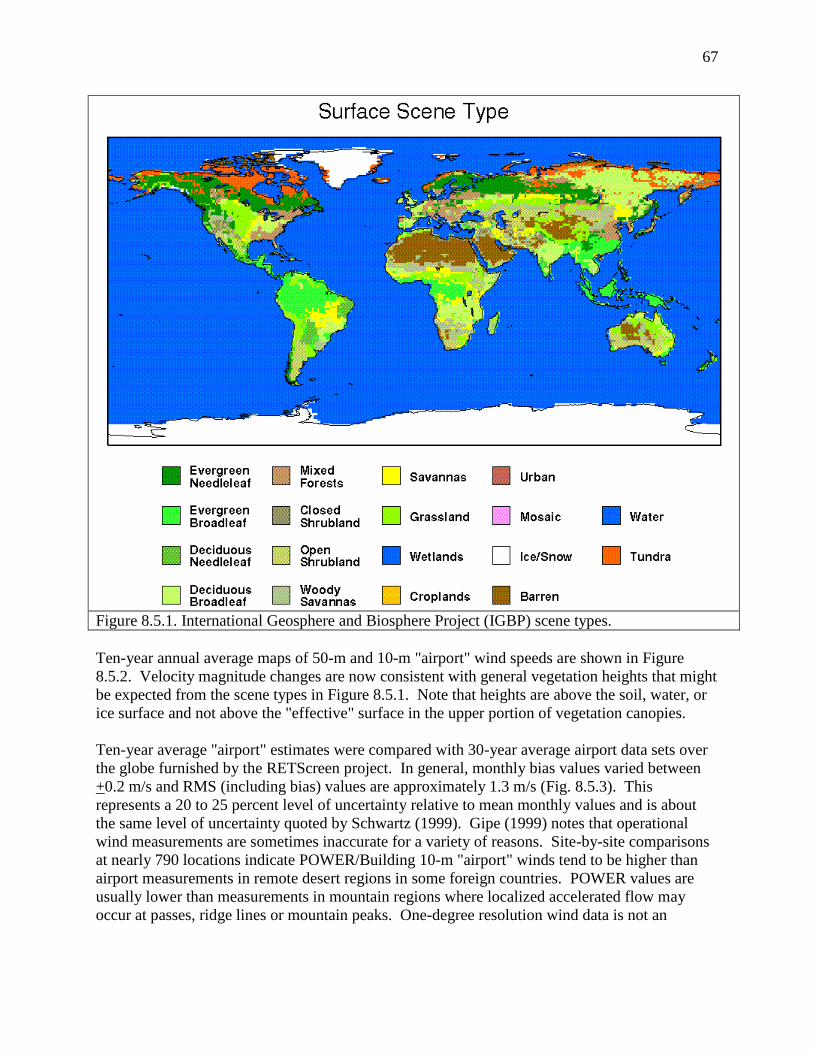
67
Figure 8.5.1. International Geosphere and Biosphere Project (IGBP) scene types.
Ten-year annual average maps of 50-m and 10-m "airport" wind speeds are shown in Figure
8.5.2. Velocity magnitude changes are now consistent with general vegetation heights that might
be expected from the scene types in Figure 8.5.1. Note that heights are above the soil, water, or
ice surface and not above the "effective" surface in the upper portion of vegetation canopies.
Ten-year average "airport" estimates were compared with 30-year average airport data sets over
the globe furnished by the RETScreen project. In general, monthly bias values varied between
+0.2 m/s and RMS (including bias) values are approximately 1.3 m/s (Fig. 8.5.3). This
represents a 20 to 25 percent level of uncertainty relative to mean monthly values and is about
the same level of uncertainty quoted by Schwartz (1999). Gipe (1999) notes that operational
wind measurements are sometimes inaccurate for a variety of reasons. Site-by-site comparisons
at nearly 790 locations indicate POWER/Building 10-m "airport" winds tend to be higher than
airport measurements in remote desert regions in some foreign countries. POWER values are
usually lower than measurements in mountain regions where localized accelerated flow may
occur at passes, ridge lines or mountain peaks. One-degree resolution wind data is not an

68
accurate predictor of local conditions in regions with significant topography variation or complex
water/land boundaries.
Designers of "small-wind" power sites need to consider the effects of vegetation canopies
affecting wind from either some or all directions. Trees and shrub-type vegetation with various
heights and canopy-area ratios reduce near-surface velocities by different amounts. GEOS-1
calculates 10-m velocities for a number of different vegetation types. Values are calculated by
parameterizations developed from a number of "within-vegetation" experiments in Canada,
Scandinavia, Africa, and South America. The ratio of 10-m to 50-m velocities (V10/V50) for 17
vegetation types is provided in Table 8.5.1. All values were taken from GEOS-1 calculations
except for the "airport" flat rough grass category that was taken from Gipe.
Figure 8.5.2. POWER/Building estimates of wind velocity at 50 and 10 meters above the ground,
water, or snow/ice surface.

69
Figure 8.5.3. Comparison of monthly means based upon 10-year POWER/Building 10-m wind
speed with monthly means based upon 30-year RETScreen site data. (Note that the SSE and
Building values are identical.)

70
___________________________________________________________________________
Table 8.5.1. Wind Velocity V10/V50 Ratio for Various Vegetation Types.
Northern hemisphere month 1 2 3 4 5 6 7 8 9 10 11 12
35-m broadleaf-evergreen trees (70%) small type 0.47 0.47 0.47 0.47 0.47 0.47 0.47 0.47 0.47 0.47 0.47 0.47
20-m broadleaf-deciduous trees (75%) 0.58 0.57 0.56 0.55 0.53 0.51 0.49 0.51 0.53 0.55 0.56 0.57
20-m broadleaf & needleleaf trees (75%) 0.44 0.47 0.50 0.52 0.53 0.54 0.54 0.52 0.50 0.48 0.46 0.45
17-m needleleaf-evergreen trees (75%) 0.50 0.53 0.56 0.58 0.57 0.56 0.55 0.55 0.55 0.54 0.53 0.52
14-m needleleaf-deciduous trees (50%) 0.52 0.53 0.55 0.57 0.57 0.58 0.58 0.54 0.51 0.49 0.49 0.50
18-m broadleaf trees (30%)/groundcover 0.52 0.52 0.52 0.52 0.52 0.52 0.52 0.52 0.52 0.52 0.52 0.52
0.6-m perennial groundcover (100%) 0.65 0.65 0.65 0.65 0.65 0.65 0.65 0.65 0.65 0.65 0.65 0.65
0.5-m broadleaf (variable %)/groundcover 0.65 0.65 0.65 0.65 0.65 0.65 0.65 0.65 0.65 0.65 0.65 0.65
0.5-m broadleaf shrubs (10%)/bare soil 0.65 0.65 0.65 0.65 0.65 0.65 0.65 0.65 0.65 0.65 0.65 0.65
0.6-m shrubs (variable %)/groundcover 0.65 0.65 0.65 0.65 0.65 0.65 0.65 0.65 0.65 0.65 0.65 0.65
Rough bare soil 0.70 0.70 0.70 0.70 0.70 0.70 0.70 0.70 0.70 0.70 0.70 0.70
Crop: 20-m broadleaf-deciduous trees (10%)
& wheat 0.64 0.62 0.69 0.57 0.57 0.57 0.57 0.57 0.57 0.59 0.61 0.63
Rough glacial snow/ice 0.57 0.59 0.62 0.64 0.64 0.64 0.64 0.64 0.62 0.59 0.58 0.57
Smooth sea ice 0.75 0.78 0.83 0.86 0.86 0.86 0.86 0.82 0.78 0.74 0.74 0.74
Open water 0.85 0.85 0.85 0.85 0.85 0.85 0.85 0.85 0.85 0.85 0.85 0.85
"Airport": flat ice/snow 0.85 0.85 0.85 0.85 0.85 0.85 0.85 0.85 0.85 0.85 0.85 0.85
"Airport": flat rough grass 0.79 0.79 0.79 0.79 0.79 0.79 0.79 0.79 0.79 0.79 0.79 0.79
Note: 10-m and 50-m heights are above soil, water, or ice surfaces, not above the "effective" surface near
the tops of vegetation.
Daily Mean Wind Speed: For the time period January 1, 1983 – December 31, 2007 the daily
means winds in the POWER/Sustainable Buildings archive are from the GEOS-4 assimilation
model. For the time period January 1, 2008 to within several days of current time the daily
means winds are from the GEOS-5 assimilation model. The model winds are at 10m elevation
above the Earth’s surface. Testing of these winds was performed through comparison with wind
measurements reported in the NCEI GSOD files.
GEOS-4 Winds: Comparison of ground site observation reported in the NCEI GSOD files with
the 10m GEOS-4 winds for various time periods and regions have typically resulted in the
GEOS-4 values being about ½ the ground observations. Table 8.5.2 gives the yearly averaged
bias, RMSE, slope, intercept, and R^2 for a global comparisons of 2007 wind data. The last
column in this table gives the total number of daily values in the comparison.
Table 8.5.2 Summary of statistics for comparison of GEOS-4 10m daily winds to ground
observations during 2007.
Bias RMSE Slope Intercept R^2 Daily Values
0.011 1.76 0.55 1.62 0.42 1,224,453
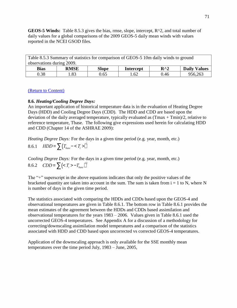
71
GEOS-5 Winds: Table 8.5.3 gives the bias, rmse, slope, intercept, R^2, and total number of
daily values for a global comparisons of the 2009 GEOS-5 daily mean winds with values
reported in the NCEI GSOD files.
Table 8.5.3 Summary of statistics for comparison of GEOS-5 10m daily winds to ground
observations during 2009.
Bias RMSE Slope Intercept R^2 Daily Values
0.38 1.83 0.65 1.62 0.46 956,263
(Return to Content)
8.6. Heating/Cooling Degree Days: An important application of historical temperature data is in the evaluation of Heating Degree
Days (HDD) and Cooling Degree Days (CDD). The HDD and CDD are based upon the
deviation of the daily averaged temperature, typically evaluated as (Tmax + Tmin)/2, relative to
reference temperature, Tbase. The following give expressions used herein for calculating HDD
and CDD (Chapter 14 of the ASHRAE 2009):
Heating Degree Days: For the days in a given time period (e.g. year, month, etc.)
8.6.1
HDD= Tbase- < Ti >( )å+
Cooling Degree Days: For the days in a given time period (e.g. year, month, etc.)
8.6.2
CDD= < Ti > -Tbase( )+
å
The “+” superscript in the above equations indicates that only the positive values of the
bracketed quantity are taken into account in the sum. The sum is taken from i = 1 to N, where N
is number of days in the given time period.
The statistics associated with comparing the HDDs and CDDs based upon the GEOS-4 and
observational temperatures are given in Table 8.6.1. The bottom row in Table 8.6.1 provides the
mean estimates of the agreement between the HDDs and CDDs based assimilation and
observational temperatures for the years 1983 – 2006. Values given in Table 8.6.1 used the
uncorrected GEOS-4 temperatures. See Appendix A for a discussion of a methodology for
correcting/downscaling assimilation model temperatures and a comparison of the statistics
associated with HDD and CDD based upon uncorrected vs corrected GEOS-4 temperatures.
Application of the downscaling approach is only available for the SSE monthly mean
temperatures over the time period July, 1983 – June, 2005,

72
Table 8.6.1
Bias
(HDD)
Bias
(%)
RMSE
(HDD)
RMSE
(%) Slope
Intercept
(HDD) Rsqd
Bias
(CDD)
Bias
(%)
RMSE
(CDD)
RMSE
(%) Slope
Intercept
(CDD) Rsqd
1983 16.30 6.44 68.59 27.11 1.03 9.85 0.95 -4.78 -8.93 28.53 53.34 0.86 2.68 0.92 1101
1984 16.37 6.34 64.45 24.97 1.03 8.46 0.95 -4.25 -8.35 27.01 53.07 0.86 2.86 0.92 1127
1985 16.13 6.01 64.31 23.97 1.03 9.19 0.96 -5.96 -11.21 27.82 52.33 0.85 1.80 0.92 1102
1986 14.07 5.55 85.41 33.72 0.98 18.25 0.91 -6.60 -12.50 27.73 52.56 0.84 1.91 0.93 1162
1987 14.92 5.91 69.30 27.42 1.02 10.71 0.94 -6.21 -12.01 27.17 52.52 0.85 1.76 0.93 1140
1988 15.20 6.20 65.39 26.68 1.03 6.79 0.95 -5.53 -10.10 27.39 50.05 0.86 2.22 0.93 1155
1989 14.71 5.85 66.75 26.54 1.03 7.55 0.95 -6.29 -11.91 29.02 54.96 0.84 2.35 0.91 1194
1990 16.84 7.09 66.45 27.97 1.04 7.67 0.95 -6.63 -11.92 28.70 51.60 0.83 2.66 0.93 1258
1991 14.69 6.03 78.74 32.33 1.01 11.89 0.92 -6.93 -11.60 30.28 50.71 0.84 2.59 0.92 1223
1992 12.94 5.19 79.58 31.91 1.00 12.11 0.92 -4.94 -10.62 25.52 54.79 0.86 1.80 0.92 1373
1993 17.79 6.94 71.34 27.83 1.03 10.14 0.94 -5.32 -9.97 26.29 49.30 0.88 1.10 0.93 1477
1994 22.88 9.24 72.22 29.17 1.05 11.59 0.95 -6.12 -10.75 27.96 49.09 0.87 1.36 0.93 1508
1995 17.54 7.10 70.60 28.60 1.03 9.83 0.95 -5.38 -9.13 28.04 47.55 0.87 2.28 0.93 1311
1996 10.15 4.64 99.68 45.60 0.93 25.32 0.84 -6.66 -10.70 30.31 48.68 0.86 2.09 0.92 1216
1997 19.61 8.56 62.21 27.16 1.05 7.08 0.95 -6.39 -11.33 28.24 50.06 0.85 2.02 0.92 1497
1998 24.65 11.56 68.35 32.06 1.09 5.74 0.94 -5.19 -8.91 27.48 47.17 0.87 2.30 0.93 1487
1999 18.58 8.53 61.38 28.18 1.06 6.22 0.95 -3.92 -6.53 28.87 48.11 0.88 3.01 0.92 1832
2000 17.61 7.32 66.54 27.67 1.05 6.15 0.95 -3.23 -6.06 27.74 52.00 0.88 3.06 0.92 2324
2001 24.33 9.94 64.77 26.46 1.06 8.60 0.96 -7.08 -12.74 30.00 53.97 0.84 1.75 0.92 1799
2002 16.62 6.92 67.75 28.22 1.03 9.73 0.94 -7.95 -13.80 29.96 52.00 0.83 1.58 0.92 2382
2003 14.75 6.24 66.15 27.96 1.04 6.33 0.94 -5.84 -9.97 30.91 52.77 0.85 3.23 0.91 2676
2004 16.52 6.87 90.29 37.56 1.00 17.33 0.90 -6.14 -11.66 27.97 53.10 0.84 2.19 0.92 2704
2005 20.40 8.32 66.41 27.07 1.05 7.56 0.95 -5.80 -9.96 29.13 49.99 0.86 2.39 0.93 3020
2006 16.56 6.76 126.66 51.69 0.91 39.49 0.81 -4.88 -8.89 29.25 53.28 0.87 2.44 0.92 3077
Mean of
individual
years
17.09 7.07 73.47 30.33 1.02 11.40 0.93 -5.75 -10.40 28.39 51.37 0.86 2.23 0.92
Year
HDD using uncorrected GEOS-4 Temperatures vs ground
site observations reported in NCDC GSOD files
CDD using uncorrected GEOS-4 Temperatures vs ground
site observations reported in NCDC GSOD files No.
Stations
Comparison of yearly heating and cooling degree days: Uncorrected GEOS-4 vs ground site observations.
(Return to Content)
8.7. Surface Pressure: Recognizing that improvement in the GEOS-4 temperatures can be
achieved through adjustments associated with differences in the average elevation of the GEOS-
4 1-degree cell and that of the ground site of interest suggest that other altitude dependent
parameters, such as pressure, might also benefit in similar altitude related adjustments. Figures
8.7.1 (a-c) illustrate significant improvements in the GEOS-4 surface pressure values (p) by
using the hypsometric equation (8.7.1), relating the thickness (h) between two isobaric surfaces
to the mean temperature (T) of the layer.
(8.7.1) h = z1 – z2 = (RT/g)ln(p1/p2) where:
z1 and z2 are the geometric heights at p1 and p2,
R = gas constant for dry air, and
g = gravitational constant.
Figure 8.7.1a shows the scatter plot of the GEOS-4 pressure at 2-meters versus the observations
reported in the NCEI archive for 2004. Figure 8.7.1b shows the agreement with the application
of equation 1, using the 2m daily mean temperature with no correction to the GEOS-4
temperatures (e.g. no lapse rate or offset correction). Figure 8.7.1c shows the scatter plot where
the GEOS-4 surface pressure and temperature have been corrected for elevation differences.

73
Clearly, adjustment to the GEOS-4 surface pressures using equation 1 results in significant
improvements to the estimates of the NCEI station pressures.
(a)
(b)
(c )
Figure 8.7.1. Panel (a) is a scatter plot of the
uncorrected GEOS-4 pressures vs. ground
observation in the NCEI GSOD-files. Panel
(b); Panel (b) is the scatter plot of the NCEI
pressures vs the GEOS-4 pressure corrected
according to Eq. 8.7.1 and the GEOS-4 2m
temperature; Panel (c) is the scatter plot of the
NCEI pressure and the GEOS-4 pressure
according to Eq. 8.7.1 where now the GEOS-
4 temperature is also corrected according to
Appendix D Eq. B.3
(Return to Content)
9. Parameters for Sizing Battery or Other Energy –Storage Systems Solar energy systems that are not connected to an electrical grid system usually require back-up or storage
equipment to provide energy during unusually cloudy days. Unusually cloudy conditions occurring over a
number of consecutive days continually draw reserve power from batteries or other storage devices for
solar systems not connected to an electrical grid. Storage devices must be designed to withstand
continuous below-average conditions in various regions of the globe. Various industry organizations
use different methods to size either battery or other types of backup systems. One international
organization has required that all stand-alone medical equipment that it purchases must operate
for 6 BLACK or NO-SUN days in parts of the tropics. The methods used require different solar

74
irradiance parameters. Three types of parameters are provided in the SSE data set. They are
listed in Table 9.1 and described in the subsequent text and in Whitlock et al (2005).
Table 9.1. Parameters for Sizing Battery or other Energy-storage Systems:
Minimum available irradiance as % of average values over consecutive-day period
Solar Insolation deficits below expected values over consecutive-day period
Equivalent number of NO-SUN days over consecutive-day period
Available Surplus Insolation Over Consecutive –day period (%)
(Return to Content)
9.1 Minimum percentage Irradiance over a consecutive-day period (1, 3, 7, 14, or 21 days) is the difference between the multi-year (Jul 1983 - Jun 2005) monthly averaged irradiance and
the multi-year monthly averaged minimum irradiance over the indicated number of days (1, 3, …
days) within each month. The average is computed over the indicated days is a running average
within each month. The defining equations are given below.
For month j, and year k the running average of the daily irradiance over p days is given by
<SRAD>p
jk = [ ∑p
i=i(<SRAD>ijk)]/p
Where:
<SRAD>ijk= Daily averaged surface irradiance for day i, in month j, and year k
i = day in month for j
j = month of year
k = year in n-year time multi-year span (Jul 1983 - Jun 2005)
p = averaging period =1, 3, 7, 14, or 21 days
The multi-year monthly average of the running sum of irradiance over the consecutive p-day
average in month j is given by
<SRAD>p
j = ∑n
k=1(<SRAD>p
jk)/n
Where:
n = 22 the number years in time span from Jul. 1983 – Jun 2005
The parameter Min/p-day for month j is the % difference between multi-year monthly average
value, <SRAD>p
j, and the minimum value of <SRAD>p
j over the 1983 – 2005 time period and
is given by
[Min/p-day]p
j= 100 – (100*[<SRAD>p
j - <SRADmin>p
j]/ <SRAD>pj)
<SRADmin>p
j = MIN(<SRAD>p
j)
(Return to Content)
9.2 Solar radiation deficits below expected values incident on a horizontal surface over a
consecutive-day period is the multi-year monthly averaged deficit calculated as following

75
<SRADdef>p
j = <SRADsum>p
j - <SRADsummin>p
j
where
<SRADsum>p
j = ∑n
k=1(<SRADsum>p
jk)/n
<SRADsum>p
j = ∑n
k=1(<SRADsum>p
jk)/n
(SRADsum)p
jk = ∑p
i=1(<SRAD>ijk)
<SRAD>ijk= Daily averaged surface irradiance for day i, in month j, and year k
i = day in month for j
j = month of year
k = year in n-year time multi-year span (Jul 1983 - Jun 2005)
p = running average period =1, 3, 7, 14, or 21 days
And
<SRADsumMin>p
j = MIN(<SRADsum>p
j)
(Return to Content)
9.3 Equivalent number of NO-SUN or BLACK days is based upon the deficit solar radiation
below expected multi-year monthly averaged value and calculated as follows:
<NoSunDa> p
j = <SRADdef>p
j / <SRAD> p
j
Where:
<SRADdef>p
j = <SRADsum>p
j - <SRADsumMin>p
j
<SRADsum>p
j = ∑n
k=1(<SRADsum>p
jk)/n
<SRADsum>p
j = ∑n
k=1(<SRADsum>p
jk)/n
(SRADsum)p
jk = ∑p
i=1(<SRAD>ijk)
<SRADsumMin>p
j = MIN{(SRADsum)p
jk}
And
<SRAD> j = ∑
nk=1(<SRAD>jk)/n = multi-year monthly averaged for month j
<SRAD>jk = ∑m
i=1(<SRAD>ijk)/m = monthly average SRAD for month j in year k
<SRAD>ijk = daily averaged solar irradiance for day i, in month j, in year k.
i = day in month for j
j = month of year
k = 22 = number of years multi-year span (Jul 1983 - Jun 2005)
m = days in month j
(Return to Content)
9.4 Available Surplus Insolation Over Consecutive –day period (1, 3, 7, 14, or 21 days) is
calculated for each month as the climatological average (i.e. multi-year monthly average ) over
the 22-year period (July 1983 – June 2005) as a percentage of the expected average insolation
over the same consecutive day period. The parameter Max/p-day for month j is the % difference
between multi-year monthly average value, <SRAD>p
j, and the maximum value of <SRAD>p
j

76
over the 1983 – 2005 time period. The following summarizes the procedure for calculating the
multi-year monthly average value of Max/p-day
[Max/p-day]p
j = 100 – (100*[<SRAD>p
j - <SRADmax>pj]/ <SRAD>
pj)
Where
<SRAD>p
j = ∑n
k=1(<SRAD>p
jk)/n
= The multi-year monthly average of <SRAD>p
jk for month j
<SRAD>p
jk = [ ∑p
i=i(<SRAD>ijk)]/p = The running average of the daily insolation over p days
for month j & year k
<SRAD>ijk= Daily averaged surface insolation for day i, in month j, and year k
i = day in month for j
j = month of year
k = year in n-year time multi-year span (Jul 1983 - Jun 2005)
p = averaging period =1, 3, 7, 14, or 21 days
n = 22 the number years in time span from Jul. 1983 – Jun 2005
<SRADmax>p
j = MAX(<SRAD>p
j)
(Return to Content)
10. Solar Geometry.
Multi-year monthly averaged solar geometry parameters are available for any latitude/longitude
via the “Data Tables for a particular location” web application. Table 10.1 lists the solar
geometry parameters provided to assistance users in setting up solar panels. Appendix C
provides the equations for calculating each of the parameters, while Appendix B describes the
methodology for calculating the multi-year monthly averages. Note that each of the solar
geometry parameters is calculated for the “monthly average day”; consequently each parameter
is the monthly “averaged” value for the respective parameter for the given month. The “monthly
average day” is the day in the month whose solar declination ( ) is closest to the average
declination for that month (Klein 1977). Table 10.1 lists the date and average declination, , for
each month.
Table 10.1. Multi-year monthly averaged solar geometry parameters for each User
provided latitude/longitude that are calculated based upon the “monthly average
day”. These parameters provide guidance for solar panels.
Solar Geometry:
Solar Noon
Daylight Hours
Daylight average of hourly cosine solar zenith angles
Cosine solar zenith angle at mid-time between sunrise and solar noon (Eq)
Declination
Sunset Hour Angle
Maximum solar angle relative to the horizon
Hourly solar angles relative to the horizon
Hourly solar azimuth angles

77
Table 10.2. List of the day in the month whose solar declination, , is closest to the average
declination for that month
Month Date in month () Month Date in month ()
January 17 -20.9 July 17 21.2
February 16 -13.0 August 16 13.5
March 16 -2.4 September 15 2.2
April 15 9.4 October 15 -9.6
May 15 18.8 November 14 -18.9
June 11 23.1 December 10 -23.0
(Return to Content)
11. References
Adler, R.F., G.J. Huffman, A. Chang, R. Ferraro, P. Xie, J. Janowiak, B. Rudolf, U. Schneider,
S. Curtis, D. Bolvin, A. Gruber, J. Susskind, P. Arkin, E. Nelkin 2003: The Version 2 Global
Precipitation Climatology Project (GPCP) Monthly Precipitation Analysis (1979-Present). J.
Hydrometeor., 4, 1147-1167.
Bai, J., X. Chen, A. Dobermann, H. Yang, K.G. Cassman, and F. Zhang. 2010. Evaluation of
NASA satellite- and model-derived weather data for simulation of maize yield potential in
China. Agron. J. 102:9–16. doi:10.2134/agronj2009.0085
Barry, R. G. and R. J. Chorley, 1987: Atmosphere, Weather, and Climate. 5th ed. Methuen, 460
Blandford, Troy R., Karen S. Blandford, Bruan J. Harshburger, Brandon C. Moore, and Von P.
Walden. Seasonal and Synoptic Variations in near-Surface Air Temperature Lapse Rates in a
Mountainous Basin. J. Applied Meteorology and Climatology. 2008, Vol. 47, 249 – 261.
Bloom, S., A. da Silva, D. Dee, M. Bosilovich, J.-D. Chern, S. Pawson, S. Schubert, M.
Sienkiewicz, I. Stajner, W.-W. Tan, M.-L. Wu, Documentation and Validation of the Goddard
Earth Observing System (GEOS) Data Assimilation System - Version 4, Technical Report Series
on Global Modeling and Data Assimilation, NASA/TM—2005–104606, Vol. 26, 2005
Bolvin, David T., Robert F. Adler, George J. Huffman, Eric J. Nelkin, Jani P. Poutiainen, 2009:
Comparison of GPCP Monthly and Daily Precipitation Estimates with High-Latitude Gauge
Observations. J. Appl. Meteor. Climatol., 48, 1843–1857. doi: 10.1175/2009JAMC2147.1
Braun, J. E. and J. C. Mitchell, 1983: Solar Geometry for Fixed and Tracking Surfaces. Solar
Energy, Vol. 31, No. 5, pp. 439-444.

78
Briggs, Robert S., R. G. Lucas, Z. T. Taylor, 2003: Climate Classification for Building Energy
Codes and Standards. Technical Paper, Pacific NW National Laboratory, March 26, 2002.
Continue to use original climate zone definitions.
Collares-Pereira, M. and A. Rabl, 1979: The Average Distribution of Solar Radiation-
Correlations Between Diffuse and Hemispherical and Between Daily and Hourly Insolation
Values. Solar Energy, Vol. 22, No. 1, pp. 155-164.
Dorman, J. L. and P. J. Sellers, 1989: A Global Climatology of Albedo, Roughness Length and
Stomatal Resistance for Atmospheric General Circulation Models as Represented by the Simple
Biosphere Model (SiB). Journal of Atmospheric Science, Vol. 28, pp. 833-855.
Encyclopedia of Agricultural, Food, and Biological Engineering edited by Dennis R. Heldman
Page 189
Erbs, D. G., S. A. Klein, and J. A. Duffie, 1982: Estimation of the Diffuse Radiation Fraction for
Hourly, Daily and Monthly average Global Radiation. Solar Energy, Vol. 28, No. 4, pp. 293-
302.
Flatau, J. Piotr, Robert L. Walko, and William R. Cotton, 1992: Polynomial Fits to Saturation
Vapor Pressure. Notes and Correspondence, Journal of Applies Meteorology. 1507-1513.
Gipe, Paul, 1999: Wind Energy Basics, Chelsea Green Publishing, 122 pp.
Gupta, S. K., D. P. Kratz, P. W. Stackhouse, Jr., and A. C. Wilber, 2001: The Langley
Parameterized Shortwave Algorithm (LPSA) for Surface Radiation Budget Studies. NASA/TP-
2001-211272, 31 pp. Available on-line at: http://ntrs.nasa.gov/search.jsp
Harlow, R. C., E. J. Burke, R. L. Scott, W. J. Shuttleworth, C. M. Brown, and J. R. Petti.
Derivation of temperature lapse rates in semi-arid south-eastern Arizona, (2004) Hydrol. and
Earth Systems Sci, 8(6) 1179-1185.
Iribarne, J.V. and W.L. Godson, 1981: Atmospheric Thermodynamics. Geophysics and
Astrophysics Monographs, D. Riedel Publishing Company, Dordrecht, Netherlands.
Jupp, D. L. B.; 2003,Calculating and converting between common water vapour measures in
meteorological data and their use in support of earth observation validation, CSIRO Earth
Observation Centre Technical Report, 2003/01.
Klein, S.A., 1977: Calculation of monthly average insolation on tilted surfaces. Solar Energy,
Vol. 19, pp. 325-329.
Liu, B. Y. H. and R. C. Jordan, 1960: The Interrelationship and Characteristic Distribution of
Direct, Diffuse, and Total Solar Radiation. Solar Energy, Vol. 4, No. 3, pp. 1-19.

79
Lookingbill, Todd R. and Dean L. Urban, Spatial estimation of air temperature differences for
landscape-scale studies in mountain environments, (2003) Agri. and Forst. Meteor, 114(3-4)
141-151.
McPhee, James, Steven A. Margulis, 2005: Validation and Error Characterization of the GPCP-
1DD Precipitation Product over the Contiguous United States. J. Hydrometeor, 6, 441–459.
doi: 10.1175/JHM429.1
Ohmura, Atsumu, Ellsworth G. Dutton, Bruce Forgan Claus Fröhlich Hans Gilgen, Herman
Hegner, Alain Heimo, Gert König-Langlo, Bruce McArthur, Guido Mueller, Rolf Philipona,
Rachel Pinker, Charlie H. Whitlock, Klaus Dehne, and Martin Wild, 1998: Baseline Surface
Ohmura, A., E. Dutton, B. Forgan, C. Frohlich, H. Gilgen, H. Hegne, A. Heimo, G. Konig-
Langlo, B. McArthur, G. Muller, R. Philipona, C. Whitlock, K. Dehne, and M. Wild, 1998:
Baseline Surface Radiation Network (BSRN/WCRP): New precision radiometery for climate
change research. Bull. Amer. Meteor. Soc. 79 No. 10, 2115-2136
Pinker, R., and I. Laszlo, 1992: Modeling Surface Solar Irradiance for Satellite Applications on a
Global Scale. J. Appl. Meteor., 31, 194–211.
Radiation Network (BSRN/WCRP): New Precision Radiometry for Climate Research, Bull. Of
American Meteor. Soc., 79, 10, p 2115-2136.
RETScreen: Clean Energy Project Analysis: RETScreen® Engineering & Cases Textbook, Third
Edition, Minister of Natural Resources Canada, September 2005.
(http://www.retscreen.net/ang/12.php, Engineering e-Textbook, Version 4, RETScreen
Photovoltaic Project Analysis Chapter, pp. PV.15-PV.21, ISBN: 0-662-35672-1, Catalogue no.:
M39-99/2003E-PDF).
Rossow, W.B., and R.A. Schiffer, 1999: Advances in understanding clouds from ISCCP. Bull.
Amer. Meteorol. Soc., 80, 2261-2288, doi:10.1175/1520-
0477(1999)080<2261:AIUCFI>2.0.CO;2.
Schwartz, Marc, 1999: Wind Energy Resource Estimation and Mapping at the National
Renewable Energy Laboratory. NREL Conf. Pub. NREL/CP-500-26245.
Smith, G.L., R. N. Green, E. Raschke, L. M. Avis, J. T. Suttles, B. A. Wielicki, and R. Davies,
1986: Inversion methods for satellite studies of the Earth's radiation budget: Development of
algorithms for the ERBE mission. Rev. Geophys., 24, 407-421.
Surface Weather Observations and Reports, Federal Meteorological Handbook No. 1, FCM-H1-
2005, Washington, D.C., 2005
Rasch, P. J., N. M. Mahowald, and B. E. Eaton (1997), Representations of transport, convection,
and the hydrologic cycle in chemical transport models: Implications for the modeling of short-
lived and soluble species, J. Geophys. Res., 102(D23), 28, 127-128, 138.

80
Takacs, L. L., A. Molod, and T. Wang, 1994: Volume 1: Documentation of the Goddard Earth
Observing System (GEOS) general circulation model - version 1, NASA Technical
Memorandum 104606, Vol. 1, 100 pp.
White, Jeffrey W. , Gerrit Hoogenboom, aul W. Stackhouse Jr., and James M. Hoell, Evaluation
of NASA satellite- and assimilation model-derived long-term daily
temperature data over the continental US, Agric. Forest Meteorol. (2008),
doi:10.1016/j.agrformet.2008.05.017
White, Jeffrey W. , Gerrit Hoogenboom, Paul W. Wilkens, Paul W. Stackhouse Jr., and James
M. Hoell, Evaluation of Satellite-Based, Modeled-Derived Daily Solar Radiation Data for the
Continental United States. Agron. J. 103:1242-1251(2011)
(Return to Content)

81
Appendix A
Validation Methodology
The following are the expressions used to calculate the statistical parameters:
The Pearson's correlation coefficient is calculated using equation A-1:
(A-1)
where:
n = number of data samples
xi and yi represent the surface and POWER data respectively
(A-2)
is the sample mean and analogously for
(A-3)
is the standard deviation of sample xi and similarly for yi
The expression for the Mean Bias Error (MBE) between POWER Parm values and observations
of Parm at a single surface site, j, is given as:
(A-4) (MBE)j = {∑i{[(Parmi
j)power - (Parmi
j)Sur]}}/n
Where
i = day within given time period
j = site number
n = number of data pairs within given time period
∑i = sum over all data pairs at site j
The expression for the MBE for multiple surface sites is given as:
(A-5) MBE = {∑i(MBE)j}/N
Where the sum ∑i is over all sites

82
N = total number of sites
The expression for the RMSE between for POWER parameter, Parm, and surface observation of
Parm at a single site j is given as
(A-6) (RMSE)j = {{∑i[(Parmi
j)power - (Parmi
j)Sur ]
2}/n}}1/2
,
Where
i = day within given time period
j = site number
n = number of data pairs within given time period
∑i = sum over all data pairs at site j
And the RMSE for multiple sites’
(A-7) RMSE = {∑i(RMSE)j}/N
(Return to Content)

83
Appendix B
Averaging Methodology
Methodology for calculating monthly, annual & climatologically averaged parameters: In
general, daily averages were calculated for local solar time and stored using 3-hourly data from
the Global Modeling and Assimilation Office (GMAO) data archive for the meteorological
parameters and from the NASA/GEWEX Surface Radiation Budget Release-3.0 data sets for the
solar parameters. Monthly averages by year were calculated from the dailies; annual averages, by
year, were calculated from the monthly averages for the given year (i.e. the sum of the monthly
averages divided by the number of months in the year, typically 12); climatologically (22-year)
averages for a given month (e.g. multi-year monthly averages) were calculated as a sum of the
monthly averages divided by the number of months (i.e. typically 22); climatologically annual
averages were calculated as a sum of the climatologically averaged monthly averages divided by
the number of months (typically 12).
The daily average of parameter Parm for day i, in month j, and year k is given by:
Where
Is the average values of Parm over the 3-hour period h and N =number of 3-hourly values for the given day. The monthly average by year of parameter Parm for month j in year k is given by:
Where
Is the daily average of parameter Parm for day i, in month j and year k and d = number of days in month j. The annual average of Parameter Parm for year k is given by
Where
Is the monthly average of parameter Parm, for month j and in year k and m = number monthly averages in year k.

84
The climatologically monthly average (i.e. multi-year monthly average) of parameter Parm for month j over n years is given by:
Where
Is the monthly average of parameter Parm for month j, in year k and n = number of years in climate time period.
(Return to Content)

85
APPENDIX C: Solar Geometry
The solar geometry parameters useful for designing and application of solar panels are available
for each User defined Latitude/Longitude. These parameters and equations used to calculate
each parameter are given below.
C-1. Monthly Averaged Solar Noon (GMT time)
SN = 60 * hr + mn + 4 * (lon – merid) + 60*lon/15.0
SN= Solar Noon
lon = local longitude (user input); positive = East; negative West
merid = meridian through local time zone; positive = East; negative West
hr = hour
mn = minute
Return to Solar Geometry Section
C-2. Monthly Averaged Daylight Hours (hours)
From John A. Duffie and William A. Beckman, Solar Engineering of Thermal Process 2nd
edition Wiley-Interscienc3 Publication
daylight[mo] = (sMAM - rMAM) / 60.0
Where:
daylight[mo] – daylight hours for given month
sMAM = int(12.0 * 60.0 + RS -(4.0 * (lon - merid)) - eotA);
rMAM = int(12.0 * 60.0 - RS - (4.0 * (lon - merid)) - eotA);
eotA = (L - C - alpha) / 15.0 * 60.0
alpha = L - 2.466*sin(2.0*L) + 0.053*sin(4.0*L)
L = (280.460 + (36000.770 * t) + C)
– int((280.460 + (36000.770 * t) + C) / 360.0) * 360.0
C = (1.915 * sin(G))+(0.020 * sin(2.0*G))
G = (357.528 + 35999.05 * t)
- int((357.528 + 35999.05 * t) / 360.0) * 360.0
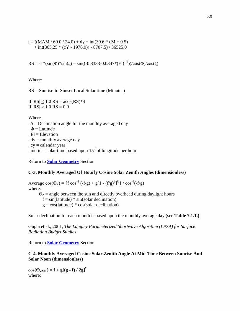
86
t = ((MAM / 60.0 / 24.0) + dy + int(30.6 * cM + 0.5)
+ int(365.25 * (cY - 1976.0)) - 8707.5) / 36525.0
RS = -1*(sin(Φ)*sin(ξ) – sin((-0.8333-0.0347*(El)1/2
))/cos(Φ)/cos(ξ)
Where:
RS = Sunrise-to-Sunset Local Solar time (Minutes)
If |RS| < 1.0 RS = acos(RS)*4
If |RS| > 1.0 RS = 0.0
Where
. = Declination angle for the monthly averaged day
. Φ = Latitude
. El = Elevation
. dy = monthly average day
. cy = calendar year
. merid = solar time based upon 150 of longitude per hour
Return to Solar Geometry Section
C-3. Monthly Averaged Of Hourly Cosine Solar Zenith Angles (dimensionless)
Average cos(ΘZ) = {f cos-1
(-f/g) + g[1 - (f/g)2]
½} / cos
-1(-f/g)
where:
ΘZ = angle between the sun and directly overhead during daylight hours
f = sin(latitude) * sin(solar declination)
g = cos(latitude) * cos(solar declination)
Solar declination for each month is based upon the monthly average day (see Table 7.1.1.)
Gupta et al., 2001, The Langley Parameterized Shortwave Algorithm (LPSA) for Surface
Radiation Budget Studies
Return to Solar Geometry Section
C-4. Monthly Averaged Cosine Solar Zenith Angle At Mid-Time Between Sunrise And
Solar Noon (dimensionless)
cos(ΘZMT) = f + g[(g - f) / 2g]½
where:

87
ΘZMT = Zenith angle at mid-time between sunrise and solar noon
f = sin(latitude) * sin(solar declination)
g = cos(latitude) * cos(solar declination)
Solar declination for each month is based upon the monthly average day (see Table 7.1.1.)
Gupta et al., 2001, The Langley Parameterized Shortwave Algorithm (LPSA) for Surface
Radiation Budget Studies
Return to Solar Geometry Section
C-5. Monthly Averaged Declination (degrees)
= 23.45*sin{(360/365)*(284+JD + Hr/24)}
Where
= Declination angle
JD = Julian day
Hr = hour
Reference: P. I. Cooper, The Absorprion of solar radiation in solar stills. Solar Energy 12, 3
(1969)
Return to Solar Geometry Section
C-6. Monthly Averaged Sunset Hour Angle (degrees)
Cos(ωs) = - tan(Φ)tan(ξ)
Where all angles for each month are based upon the monthly average day (see Table 7.1.1.)
ωs = Sunset Hour angle
= Declination angle
Φ = Latitude
If Cos(ωs) < -1.0 set Cos(ωs)= -1
If Cos(ωs) > +1.0 set Cos(ωs)= +1
ωs = acos{tan(Φ)tan(ξ)}
From John A. Duffie and William A. Beckman, Solar Engineering of Thermal Process 2nd
edition Wiley-Interscienc3 Publication
Return to Solar Geometry Section

88
C-7. Monthly Averaged Maximum Solar Angle Relative To The Horizon (degrees)
Θz = acos{sin(ξ)*sin(Φ)+cos(ξ)*cos(Φ)*cos(ω)}
Where all angles for each month are based upon the monthly average day (see Table 7.1.1.)
Θz = Zenith angle
= Declination angle
Φ = Latitude
ω = Hour angle = acos(cot(Φ)tan(ξ)
Max(Θz) = 90.0 – Θz
J. E. Braun & J. C. Mitchell Solar Geometry for Fixed and Tracking Surfaces, Solar Energy 31,
no. 5, pp 339-444 (1983)
Return to Solar Geometry Section
C-8. Monthly Averaged Hourly Solar Angles Relative To The Horizon (degrees)
ha = ((MAM - 12.0 * 60.0) / 4.0)
Where all angles for each month are based upon the monthly average day (see Table 7.1.1.)
ha = Hour Angle
MAM = Solar Minutes After Midnight
MAM = (iMAM + (4.0 * (lon - meridian) + eotA)) + 24.0 * 60.0
iMAM = 60 * hr + mn;
eotA = (L - C - alpha) / 15.0 * 60.0
alpha = L - 2.466*sin(2.0*L) + 0.053*sin(4.0*L)
L = (280.460 + (36000.770 * t) + C)
– int((280.460 + (36000.770 * t) + C) / 360.0) * 360.0
G = (357.528 + 35999.05 * t)
- int((357.528 + 35999.05 * t) / 360.0) * 360.0
C = (1.915 * sin(G))+(0.020 * sin(2.0*G))
t = ((MAM / 60.0 / 24.0) + dy + int(30.6 * cM + 0.5)
+ int(365.25 * (cY - 1976.0)) - 8707.5) / 36525.0
Return to Solar Geometry Section

89
C-9. Monthly Averaged Hourly Solar Azimuth Angles (degrees)
#azimuthAngle = aziA in Degrees
aziA= RadToDeg * acos(((sin(altA * DegToRad) *
sin(lat * DegToRad)) - sin(decl * DegToRad)) /
(cos(altA * DegToRad) * cos(lat * DegToRad)))
Where all angles for each month are based upon the monthly average day (see Table 7.1.1.)
Φ = Latitude in radians
= Declination angle in radians
ha = hour angle in radians
altA = altitude angle in
altA = (PI/2.0 - acos((cos(Φ) * cos(ξ) * cos(hA * DegToRad))
+ (sin(Φ) * sin(ξ))))
Return to Solar Geometry Section
(Return to Content)

90
Appendix D
Downscaling Assimilation Modeled Temperatures
Introduction: In section VII temperature estimates from the GEOS-4 assimilation model were
found to exhibit a globally and yearly (1983 – 2006) averaged bias for Tmax of -1.82° C , for
Tmin about +0.27°, for Tave about - 0.55° C relative to ground site observations. In this
Appendix factors contributions to these biases are noted with the main focus being the
description of a methodology that can reduce the biases for local ground site.
The spatial resolution of the GEOS-4 assimilation model’s output is initially on a global 1o by
1.25o grid and then re-gridded to a spatial 1
o by 1
o grid to be spatially compatible with the solar
insolation values available through the POWER archive. The elevation of original and re-gridded
cell represents the average elevation of the earth’s surface enclosed by the dimensions of the grid
cell. Figure D.1 illustrates the spatial features associated with a reanalysis cell and a local
ground site. In mountainous regions, in particular, the elevation of the grid cell can be
substantially different from that of the underlying ground site.
Figure D.1: Relative height and horizontal features associated with a nominal 1-degree cell and
a local ground site in the mountains.
The inverses dependence of the air temperature on elevation is well known and suggests that the
elevation differences between the re-analysis grid cell and the actual ground site may be a factor
contribution to the biases between the modeled and observed temperatures. In figure D.2, the
yearly averaged differences between ground site measurements and reanalysis modeled values
(i.e. bias) are plotted against the difference in the elevation of the ground site and the reanalysis
grid for the ensemble of years 1983 – 2006. The stations have been grouped into 50m elevation
difference bins (e.g. 0 to 50m; >50m to 100m; >100m to 150m; etc.) and plotted against the
mean yearly bias for the respective elevation bin.

91
(a)
(b)
(c )
Figure D.2. Scatter plots showing the dependence
of the bias between the GEOS-4 Tave (a), Tmin
(b), and Tmax ( c) temperatures and values from
the NCEI archive on the elevation difference
between the GEOS-4 cell and the ground station
elevation for the years 1983 -2006. The elevation
difference between stations are grouped into
elevation difference bins (e.g. 0 to 50m; >50m to
100m; >100m to 150m; etc.) and plotted against
the mean bias for the respective elevation bin.
The solid line is the linear least squares fit to the scatter plot and the parameters for the fit are
given in the upper right hand portion of each plot. Table D.1 gives the parameters associated
with linear regression fits to similar scatter plots for individual years and is included here to
illustrate the year-to-year consistency in these parameters. The linear dependence of the bias
between the GEOS-4 and NCEI temperature values on the elevation difference between the
GEOS-4 cell and ground elevation is clearly evident in Figure D.2 and Table D.1. The mean of
the slope, intercept, and R^2 for the individual years is given in the row labeled “Average”. The
bottom row of Table D.1 lists the fit parameters of Figure D.2.

92
(C/km) ( C ) (C/km) ( C ) (C/km) ( C )
1983 -6.2 -0.5 0.74 -4.4 0.4 0.87 -5.2 0.1 0.83
1984 -6.2 -0.6 0.72 -4.3 0.3 0.75 -5.2 0.0 0.79
1985 -6.8 -0.9 0.94 -4.7 0.1 0.77 -5.9 -0.1 0.95
1986 -6.6 -0.7 0.88 -4.3 0.3 0.82 -5.5 0.1 0.91
1987 -6.3 -1.0 0.92 -4.9 0.4 0.83 -5.5 0.0 0.95
1988 -6.2 -0.7 0.76 -4.0 0.5 0.68 -5.0 0.2 0.75
1989 -6.0 -1.0 0.77 -3.4 0.1 0.55 -4.5 -0.2 0.72
1990 -6.6 -0.8 0.9 -4.4 0.2 0.83 -5.4 0.1 0.88
1991 -6.1 -0.8 0.9 -4.4 0.3 0.88 -5.2 0.1 0.9
1992 -6.2 -0.8 0.93 -4.6 0.4 0.88 -5.2 0.0 0.93
1993 -6.1 -0.9 0.92 -5.0 0.2 0.93 -5.4 0.0 0.95
1994 -6.2 -1.0 0.92 -5.4 -0.1 0.92 -5.6 -0.2 0.95
1995 -5.9 -1.3 0.91 -5.4 0.6 0.94 -5.5 -0.1 0.95
1996 -5.3 -0.6 0.79 -4.8 0.7 0.89 -4.9 0.3 0.86
1997 -6.2 -0.8 0.94 -5.2 0.2 0.95 -5.5 -0.1 0.96
1998 -6.0 -0.9 0.9 -4.9 0.3 0.93 -5.2 -0.1 0.94
1999 -6.2 -0.9 0.94 -4.9 0.5 0.95 -5.3 0.0 0.96
2000 -6.2 -1.1 0.97 -5.0 -0.1 0.93 -5.4 -0.4 0.97
2001 -5.7 -1.4 0.9 -5.0 0.0 0.85 -5.3 -0.5 0.93
2002 -6.2 -1.1 0.97 -4.6 -0.1 0.92 -5.2 -0.4 0.97
2003 -6.1 -1.0 0.97 -4.4 -0.2 0.91 -5.1 -0.4 0.97
2004 -6.3 -0.9 0.98 -4.6 -0.2 0.94 -5.3 -0.4 0.98
2005 -6.1 -1.3 0.97 -4.6 -0.1 0.93 -5.2 -0.5 0.97
2006 -5.7 -1.3 0.95 -4.6 -0.4 0.92 -5.0 -0.6 0.96
Average -6.1 -0.9 0.90 -4.6 0.2 0.87 -5.3 -0.1 0.91
STDEV 0.3 0.2 0.08 0.4 0.3 0.10 0.3 0.2 0.07
All Years
Regression
Analysis
-6.2 -1.0 0.97 -4.6 -0.1 0.94 -5.2 -0.3 0.97
Intercept R^2Intercept R^2 Slope Slope Intercept R^2
Table A.1. Linear regression parameters associated with scatter plots of GEOS-4
yearly mean bias relative to ground site observatioions for individual years from 1983 -
2006. The bottom row gives the parametes for the scatter plots of Figure A.2.
Year
Tmax Tmin Tave
Slope
As already noted, the inverses dependence of the air temperature on elevation is well known with
-6.5oC/km typically accepted as a nominal global environmentally averaged lapse rate value
(Barry and Chorely 1987). Moreover, numerous studies have been published (Blandford et al.,
2008; Lookingbill et al., 2003; Harlow et al., 2004) that highlight the need to use seasonal and
regionally dependent lapse rates for the daily Tmin and Tmax values to adjustment ground site
observations to un-sampled sites at different elevations. In the remaining sections an approach
to statistically calibrate the assimilation model and downscale the reanalysis temperatures to a
specific site within the reanalysis grid box is described.
(Return to Content)

93
D.1. Downscaling Methodology : Figure D.2 illustrates the linear dependence of the bias
between the GEOS-4 temperatures and elevation differences between reanalysis grid cell and the
ground site elevation. In this section a mathematical procedure is developed for statistically
calibrating the GEOS-4 model relative to ground site observations resulting parameters that
allow downscaled estimates of the reanalysis temperatures at localized ground sites site values.
In subsequent sections the validity of the downscaling approach will demonstrated.
The downscaling discussed in this and subsequent sections is only available through the
POWER/Building archive with application to the monthly mean temperatures over the time
period January 1, 1983 – December 31, 2007.
If we assume that the reanalysis modeled temperatures estimates can in fact be downscaled based
upon a lapse rate correction, then we can express the downscaled temperatures at a local ground
site as
Eq. D.1. (Tgrd
)RA = (Tnat
)RA + λ*(Hgrd – HRA) + β
Where (Tgrd
)RA is the downscaled reanalysis temperature, (Tnat
)RA is the native reanalysis value
averaged over the reanalysis grid cell, λ is the seasonal/regional lapse rate (C/km) appropriate
for the given ground site, Hgrd and HRA are the elevation for ground site and reanalysis grid cell
respectively, and β is included to account for possible biases between the reanalysis model
estimates and ground observations. Assuming that Eq. D.1 provides an accurate estimate of the
air temperature we have
Eq. D.2. (Tgrd
) = (Tgrd
)RA,
where (Tgrd
) is the air temperature at the desired ground site.
Equation Eq. D.1 and Eq. D.2 can be combined to yield
Eq. D.3. (Tgrd
) = (Tnat
)RA + λ*(Hgrd – HRA) + β
or
Eq. D.4. ΔT = λ*ΔH + β
where ΔT is the differences between the air temperature at desired ground site and reanalysis cell
temperature or Bias, and ΔH is the difference between the elevation of the ground site and the
model cell. Equation Eq. D.4 gives a linear relation between ΔT and ΔH with the slope given by
λ, the lapse rate, and an intercept value given by β. B linear least squares fit to a scatter plot of
ΔT vs ΔH (i.e. Figure D.2) yields λ, the lapse rate, and β, the model bias. These parameters can
then be used to downscale the reanalysis temperature values to any ground site within a region
that the λ and β values are valid. Note that this methodology lends itself to generating λ and β

94
values averaged over any arbitrary time period and/or investigating other environmental factors
such as the influence of the vegetation type on the downscaling methodology.
The scatter plots shown in Figure D.2 are constructed using the yearly mean bias between
GEOS-4 and NCEI temperatures (i.e. ΔT ) vs the difference in the elevation between the GEOS-
4 grid cell and the ground site (i.e. ΔH). Consequently, from Eq. D.4 the slope and intercept
associated with the linear fit to the scatter plot give a set of globally averaged λ and β parameters
for downscaling the reanalysis temperatures Tave, Tmin, and Tmax to any geographical site.
Table D.2 summarizes the values for λ (e.g. lapse rate) and β (e.g. offset) based upon the use of
the NCEI GSOD meteorological data as the “calibration” source. The values given in Table D.2
are based upon the globally distributed ground sites in the NCEI GSOD data base, and are based
upon yearly mean ground and GEOS-4 data.
Table D.2. Globally and yearly and averaged lapse rate and
offset values for adjusting GEOS-4 temperatures to local
ground site values (based upon 1983 – 2006 NCEI and
GEOS-4 global data).
Lapse Rate (oC/km) Off Set (
oC)
Tmax -6.20 -0.99
Tmin -4.63 -0.07
Tave -5.24 -0.30
Figure D.3 illustrates that bias between the ground observations and the GEOS-4 values after
applying the lapse rate correction and offset values given in Table D.2 is independent of the
elevation difference between the ground site and the GEOS-4 1-degree cell and that the average
bias is also near zero.

95
(a)
(b)
( c)
Figure D.3. Scatter plots showing the dependence of
the bias between the GEOS-4 Tave (a), Tmin (b), and
Tmax (c) temperatures and values from the NCEI
archive on the elevation difference between the
GEOS-4 cell and the ground station elevation for the
years 1983 -2006 after adjusting the GEOS-4 values
using Eq. VII – 3. The elevation difference between
stations are grouped into elevation difference bins (e.g.
0 to 50m; >50m to 100m; >100m to 150m; etc.) and
plotted against the mean bias for the respective
elevation bin.
(Return to Content)
Global Downscaling: Table D.3 gives the yearly mean global MBE and RMSE of the native (i.e.
un-corrected) and downscaled GEOS-4 temperature values relative to NCEI values for the year
2007. The 2007 GEOS-4 values were downscaled via Eq. D.3 using the lapse rate and offset
parameters given in Table D.2. Since the λ and β parameters for downscaling were developed
using NCEI data over the years 1983 – 2006, the use of data from 2007 serves as an independent
data set for this test.
Table D.3. Globally and yearly averaged Mean Bias Error (MBE) and Root Mean
Square Error (RMSE) for 2007 un-corrected and downscaled GEOS-4 temperatures
relative to NCEI temperatures. The downscaled GEOS-4 values are based upon the
downscaling parameters given in Table D.2 .
Un-corrected
GEOS-4
Downscaled GEOS-4
Tmax MBE -1.58 -0.10
RMSE 3.79 3.17
Tmin MBE 0.27 0.71
RMSE 3.57 3.42

96
Tave MBE -0.50 0.22
RMSE 2.82 2.47
Note that the lapse rates and offset values given in Table D.2 are yearly averaged values based
upon globally distributed ground sites in the NCEI data base. Results from a number of studies
have indicated that tropospheric lapse rates can be seasonally and regionally dependent. Table
D.4 gives the globally and monthly averaged lapse rate and offset downscaling parameters for
GEOS-4 temperatures. These parameters were developed from eq. Eq. D.4 using the monthly
averaged temperature data over the years 1983 – 2006 in global distribution of GEOS-4 and
NCEI. Tables D.5 and D.6 give respectively the globally and monthly averaged MBE and
RMSE of the 2007 GEOS-4 temperatures relative to NCDC ground site values for the unadjusted
and downscaled respectively.
Table D.4. Globally and monthly averaged lapse rates and offset values for adjusting GEOS-4
temperatures to local ground site values. Based upon 1983 – 2006 NCEI and GEOS-4 global data.
JAN FEB MAR APR MAY JUN JUL AUG SEP OCT NOV DEC YR
Tmx λ -5.12 -5.97 -6.73 -7.2 -7.14 -6.78 -6.52 -6.44 -6.31 -5.91 -5.44 -4.85 -6.22
Tmx β -1.61 -1.57 -1.4 -1.01 -0.56 -0.29 -0.24 -0.46 -0.67 -1.08 -1.44 -1.55 -0.99
Tmn λ -4.34 -4.89 -5.17 -5.16 -4.93 -4.67 -4.46 -4.33 -4.28 -4.31 -4.6 -4.44 -4.63
Tmn β -0.96 -0.95 -0.69 -0.14 0.22 0.34 0.43 0.5 0.58 0.42 -0.06 -0.61 -0.07
Tm λ -4.49 -5.19 -5.73 -6.06 -5.91 -5.59 -5.35 -5.27 -5.14 -4.9 -4.8 -4.45 -5.24
Tm β -1.16 -1.09 -0.9 -0.34 0.17 0.42 0.51 0.35 0.13 -0.18 -0.61 -0.97 -0.3
______________________________________________________________________________
Table D.5. Globally and monthly averaged MBE and RMSE values associated with unadjusted
2007 GEOS-4 temperatures relative to 2007 NCEI GSOD temperatures.
JAN FEB MAR APR MAY JUN JUL AUG SEP OCT NOV DEC YR Tmax
MBE -2.00 -2.11 -2.00 -1.64 -1.13 -1.15 -0.84 -1.27 -1.49 -1.85 -1.73 -1.90 -1.89
Tmax
RMSE 4.04 4.00 4.01 3.75 3.73 3.64 3.57 3.64 3.66 3.72 3.71 4.02 3.79
Tmin
MBE -0.24 -0.49 -0.23 0.19 0.56 0.49 0.66 0.61 0.81 0.76 0.50 -0.41 0.27
Tmin
RMSE 4.13 4.02 3.70 3.32 3.25 3.09 3.10 3.13 3.30 3.50 3.84 4.26 3.55
Tave
MBE -1.0 -1.15 -0.88 -0.54 -0.03 -0.06 -0.13 -0.18 -0.15 -0.43 -0.59 -1.08 -0.50
Tave
RMSE 3.20 3.18 2.92 2.62 2.66 2.54 2.55 2.50 2.51 2.56 2.91 3.41 2.80

97
____________________________________________________________________________
Table D.6. Globally averaged monthly MBE and RMSE associated with downscaled 2007
temperatures relative to 2007 NCEI GSOD temperatures. The GEOS-4 temperatures were downscaled using the globally and monthly averaged λ and β values given in Table D.4.
JAN FEB MAR APR MAY JUN JUL AUG SEP OCT NOV DEC YR
Tmax
MBE 0.04 -0.07 -0.04 -0.06 0.00 -0.32 -0.08 -0.30 -0.32 -0.29 0.14 0.04 -0.10
Tmax
RMSE 3.35 3.11 3.17 2.97 3.18 3.16 3.18 3.13 3.02 2.98 3.06 3.40 3.14
Tmin
MBE 1.06 0.85 0.87 0.74 0.74 0.52 0.59 0.45 0.57 0.69 0.92 0.56 0.71
Tmin
RMSE 4.11 3.87 3.54 3.13 2.99 2.83 2.86 2.87 3.01 3.26 3.71 4.12 3.36
Tave
MBE 0.52 0.33 0.48 0.28 0.27 -0.04 0.04 -0.11 0.13 0.14 0.41 0.25 0.22
Tave
RMSE 2.94 2.69 2.44 2.11 2.22 2.18 2.24 2.16 2.12 2.20 2.61 3.06 2.41
(Return to Content)
D.3 Regional Downscaling: Eq. D.4 can also be used to develop regional specific λ and β values
which, for some applications, may be more appropriate than the yearly (Table D.3) or monthly
and globally averaged (Table D.4 ) values. As an example, Table D.7 gives the regionally and
monthly averaged λ and β values for Tmax, Tmin, and Tave along with the regionally yearly
averaged values for the Pacific Northwest region (40 - 50N, 125 – 110W). These values were
developed via Eq. 4 for the US Pacific Northwest using GEOS-4 and NCEI GSOD temperatures
over the years from 1983 through 2006.
Table D.7. Regional and monthly averaged lapse rate and offset values for adjusting GEOS-4
temperatures to local ground site values Based upon 1983 – 2006 NCEI and GEOS-4 temperatures
in the US Pacific Northwest region.
JAN FEB MAR APR MAY JUN JUL AUG SEP OCT NOV DEC YR
Tmx λ -5.13 -6.22 -7.54 -7.88 -7.09 -6.61 -6.29 -5.87 -6.09 -5.83 -5.56 -4.69 -6.23
Tmx β -1.47 -1.69 -1.63 -1.55 -1.23 -1.12 -1.03 -1.64 -1.82 -2.15 -1.74 -1.09 -1.51
Tmn λ -5.55 -6.46 -6.68 -6.06 -5.53 -5.64 -5.25 -4.77 -4.7 -4.64 -5.54 -5.37 -5.51
Tmn β -0.9 -0.69 -0.12 0.31 0.48 0.78 1.36 1.43 1.31 0.81 0.31 -0.68 0.37
Tm λ -5.35 -6.38 -7.11 -7.26 -6.55 -6.27 -5.87 -5.54 -5.58 -5.39 -5.55 -5.02 -5.98
Tm β -0.81 -0.7 -0.48 -0.06 0.4 0.7 0.97 0.58 0.2 -0.19 -0.32 -0.61 -0.02
The MBE and RMSE of the unadjusted 2007 GEOS-4 temperatures in the US Pacific Region
relative to the ground observations are given in Table D.8, and for comparison the MBE and
RMSE associated with the downscaled 2007 GEOS-4 temperatures are given in Table D.9. The

98
downscaled temperatures are based upon Eq. 3 using the regional λ and β values given in Table
7.
Table D.8. Regional monthly MBE and RMSE values associated with unadjusted 2007 GEOS-4
temperatures in the US Pacific region relative to 2007 NCEI GSOD temperatures
JAN FEB MAR APR MAY JUN JUL AUG SEP OCT NOV DEC YR Tmax
MBE -3.05 -3.41 -4.47 -3.96 -3.10 -3.47 -2.74 -3.23 -3.58 -3.77 -3.25 -3.18 -3.43
Tmax
RMSE 5.06 5.11 5.78 5.34 5.06 5.18 4.85 5.28 5.63 5.36 4.99 4.76 5.20
Tmin
MBE -2.59 -2.90 -2.85 -2.30 -1.51 -1.50 -0.34 -0.12 -0.39 -1.19 -1.40 -2.94 -1.67
Tmin
RMSE 5.58 5.32 5.03 4.45 4.18 4.36 4.25 4.22 4.33 3.95 4.71 5.53 4.66
Tave
MBE -2.40 -2.56 -3.12 -2.59 -1.52 -1.65 -0.83 -1.15 -1.54 -1.99 -2.11 -2.79 -2.02
Tave
RMSE 4.36 4.12 4.33 3.92 3.33 3.38 3.16 3.21 3.41 3.48 3.92 4.52 3.76
______________________________________________________________________________
Table D.9. Regional monthly MBE and RMSE values associated with downscaled 2007 GEOS-4
temperatures in the US Pacific region relative to 2007 NCEI GSOD temperatures. The GEOS-4 temperatures were downscaled using the regionally and monthly averaged λ and β values for the US pacific Region given in Table D.7.
JAN FEB MAR APR MAY JUN JUL AUG SEP OCT NOV DEC YR
Tmax
MBE 0.28 0.54 -0.11 0.45 0.70 0.05 0.58 0.54 0.45 0.50 0.51 -0.39 0.34
Tmax
RMSE 4.00 3.63 3.45 3.11 3.77 3.55 3.90 4.05 4.21 3.70 3.71 3.30 3.70
Tmin
MBE 0.32 0.14 -0.32 -0.41 0.01 -0.23 0.20 0.18 0.00 -0.31 0.30 -0.32 -0.04
Tmin
RMSE 4.58 3.96 3.62 3.25 3.38 3.49 3.70 3.71 3.88 3.41 4.05 4.31 3.78
Tave
MBE 0.35 0.46 -0.07 0.10 0.46 -0.08 0.33 0.28 0.28 0.15 0.22 -0.36 0.18
Tave
RMSE 3.41 2.81 2.42 2.09 2.36 2.32 2.58 2.47 2.49 2.45 2.91 3.25 2.63
As an additional point of comparison Table D.10 gives the MBE and RMSE values associated
with downscaled 2007 GEOS-4 temperatures in the US Pacific Northwest relative to 2007 NCEI

99
GSOD temperatures where the globally and monthly averaged (Table 4) downscaling parameters
(i.e. λ and β) have used.
Table D.10. MBE and RMSE associated with downscaled 2007 temperatures relative to 2007
NCEI GSOD temperatures in the US Pacific Northwest region (40 – 50N, 125 – 110W). The
GEOS-4 temperatures were downscaled using the globally and monthly averaged λ and β values
given in Table D.6
JAN FEB MAR APR MAY JUN JUL AUG SEP OCT NOV DEC YR
Tmax
MBE 0.42 0.33 -0.63 -0.33 0.05 -0.72 -0.13 -0.43 -0.63 -0.54 0.16 0.13 -0.19
Tmax
RMSE 4.02 3.60 3.48 3.08 3.71 3.62 3.86 4.05 4.24 3.71 3.67 3.28 3.69
Tmin
MBE -0.06 -0.17 -0.29 -0.29 0.05 -0.15 0.85 0.95 0.58 -0.04 0.33 -0.72 0.09
Tmin
RMSE 4.61 4.02 3.67 3.28 3.41 3.55 3.85 3.85 3.95 3.41 4.10 4.40 3.84
Tave
MBE 0.39 0.42 -0.15 -0.05 0.45 -0.05 0.60 0.41 0.20 -0.03 0.24 -0.20 0.18
Tave
RMSE 3.42 2.82 2.44 2.13 2.37 2.34 2.64 2.50 2.50 2.45 2.93 3.25 2.65
The monthly time series of MBE and RMSE values for GEOS-4 2007 temperatures relative to
NCEI ground site values provide a summary for the un-scaled and downscaled temperatures in
the US Pacific Northwest region. The 2007 downscaled GEOS-4 temperatures are based upon
the monthly averaged λ and β values developed from 1983 – 2006 GEOS-4 and NCEI data in
this region. The MBE and RMSE monthly time series values are plotted for the uncorrected
GEOS-4 and GEOS-4 downscaled using (1) yearly and global mean lapse rate and offset values,
(2) monthly mean global lapse rate and offset values, (3) yearly mean regional lapse rate and
offset values, and (4) monthly mean regional lapse rate and offset values.

100
Figure D.4. Monthly time series of the MBE (left column) and RMSE (right column) between 2007 un-scaled
and downscaled GEOS-4 and NCEI ground sites observations in the Pacific Northwest region (40 - 50N, 125
– 110W). The MBE and RMSE monthly time series values are plotted for the (1) uncorrected GEOS-
4 (i.e. LRC and OSC = 0) and GEOS-4 corrected using (2) yearly and global mean lapse rate and
offset values, (3) monthly mean global lapse rate and offset values, (4) yearly mean regional lapse rate
and offset values, and (5) monthly mean regional lapse rate and offset values. The downscaling
parameters are based upon GEOS-4 and NCEI station temperatures over the years 1983 – 2006.
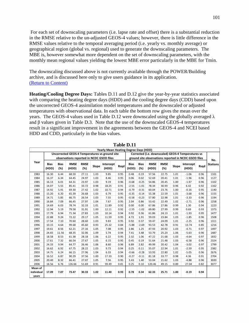
101
For each set of downscaling parameters (i.e. lapse rate and offset) there is a substantial reduction
in the RMSE relative to the un-adjusted GEOS-4 values; however, there is little difference in the
RMSE values relative to the temporal averaging period (i.e. yearly vs. monthly average) or
geographical region (global vs. regional) used to generate the downscaling parameters. The
MBE is, however somewhat more dependent on the set of downscaling parameters, with the
monthly mean regional values yielding the lowest MBE error particularly in the MBE for Tmin.
The downscaling discussed above is not currently available through the POWER/Building
archive, and is discussed here only to give users guidance in its application.
(Return to Content)
Heating/Cooling Degree Days: Tables D.11 and D.12 give the year-by-year statistics associated
with comparing the heating degree days (HDD) and the cooling degree days (CDD) based upon
the uncorrected GEOS-4 assimilation model temperatures and the downscaled or adjusted
temperatures with observational data. In each table the bottom row gives the mean over the
years. The GEOS-4 values used in Table D.12 were downscaled using the globally averaged λ
and β values given in Table D.3. Note that the use of the downscaled GEOS-4 temperatures
result in a significant improvement in the agreements between the GEOS-4 and NCEI based
HDD and CDD, particularly in the bias values.
Table D.11
Bias
(HDD)
Bias
(%)
RMSE
(HDD)
RMSE
(%) Slope
Intercept
(HDD) Rsqd
Bias
(HDD)
Bias
(%)
RMSE
(HDD)
RMSE
(%) Slope
Intercept
(HDD) Rsqd
1983 16.30 6.44 68.59 27.11 1.03 9.85 0.95 0.48 0.19 57.56 22.75 1.01 -1.06 0.96 1101
1984 16.37 6.34 64.45 24.97 1.03 8.46 0.95 0.06 0.02 52.69 20.41 1.01 -1.96 0.96 1127
1985 16.13 6.01 64.31 23.97 1.03 9.19 0.96 -0.68 -0.25 54.86 20.45 1.00 -1.97 0.96 1102
1986 14.07 5.55 85.41 33.72 0.98 18.25 0.91 -2.55 -1.01 78.34 30.93 0.96 6.42 0.92 1162
1987 14.92 5.91 69.30 27.42 1.02 10.71 0.94 -0.79 -0.31 60.04 23.76 1.00 -0.16 0.95 1140
1988 15.20 6.20 65.39 26.68 1.03 6.79 0.95 -0.35 -0.14 55.38 22.59 1.01 -3.68 0.96 1155
1989 14.71 5.85 66.75 26.54 1.03 7.55 0.95 -0.58 -0.23 57.80 22.98 1.01 -3.33 0.96 1194
1990 16.84 7.09 66.45 27.97 1.04 7.67 0.95 2.04 0.86 53.42 22.49 1.02 -2.71 0.96 1258
1991 14.69 6.03 78.74 32.33 1.01 11.89 0.92 0.00 0.00 67.86 27.86 0.99 1.30 0.94 1223
1992 12.94 5.19 79.58 31.91 1.00 12.11 0.92 -2.55 -1.02 69.80 27.99 0.99 0.69 0.93 1373
1993 17.79 6.94 71.34 27.83 1.03 10.14 0.94 0.92 0.36 61.86 24.13 1.01 -1.93 0.95 1477
1994 22.88 9.24 72.22 29.17 1.05 11.59 0.95 4.72 1.91 59.03 23.84 1.03 -1.85 0.96 1508
1995 17.54 7.10 70.60 28.60 1.03 9.83 0.95 0.92 0.37 59.47 24.09 1.01 -2.25 0.96 1311
1996 10.15 4.64 99.68 45.60 0.93 25.32 0.84 -5.88 -2.69 93.53 42.78 0.91 13.74 0.85 1216
1997 19.61 8.56 62.21 27.16 1.05 7.08 0.95 2.86 1.25 47.93 20.92 1.03 -4.71 0.97 1497
1998 24.65 11.56 68.35 32.06 1.09 5.74 0.94 7.41 3.48 53.79 25.23 1.06 -5.63 0.96 1487
1999 18.58 8.53 61.38 28.18 1.06 6.22 0.95 2.32 1.06 47.22 21.68 1.03 -4.64 0.97 1832
2000 17.61 7.32 66.54 27.67 1.05 6.15 0.95 0.45 0.19 51.64 21.48 1.03 -6.58 0.96 2324
2001 24.33 9.94 64.77 26.46 1.06 8.60 0.96 6.89 2.82 49.99 20.42 1.04 -3.02 0.97 1799
2002 16.62 6.92 67.75 28.22 1.03 9.73 0.94 0.25 0.11 55.07 22.94 1.01 -2.59 0.95 2382
2003 14.75 6.24 66.15 27.96 1.04 6.33 0.94 -0.66 -0.28 53.93 22.80 1.02 -5.05 0.96 2676
2004 16.52 6.87 90.29 37.56 1.00 17.33 0.90 -0.27 -0.11 81.18 33.77 0.98 4.36 0.91 2704
2005 20.40 8.32 66.41 27.07 1.05 7.56 0.95 3.43 1.40 53.04 21.62 1.03 -4.88 0.96 3020
2006 16.56 6.76 126.66 51.69 0.91 39.49 0.81 0.25 0.10 120.46 49.15 0.89 27.04 0.82 3077
Mean of
individual
years
17.09 7.07 73.47 30.33 1.02 11.40 0.93 0.78 0.34 62.33 25.71 1.00 -0.19 0.94
Yearly Mean Heating Degree Days (HDD) Uncorrected GEOS-4 Temperatures vs ground site
observations reported in NCDC GSOD files Year
No.
Stations
Corrected (i.e. downscaled) GEOS-4 Temperatures vs
ground site observations reported in NCDC GSOD files

102
Table D.12
Bias
(CDD)
Bias
(%)
RMSE
(CDD)
RMSE
(%) Slope
Intercept
(CDD) Rsqd
Bias
(CDD)
Bias
(%)
RMSE
(CDD)
RMSE
(%) Slope
Intercept
(CDD) Rsqd
1983 -4.78 -8.93 28.53 53.34 0.86 2.68 0.92 2.29 4.28 28.59 53.45 0.94 5.27 0.91 1101
1984 -4.25 -8.35 27.01 53.07 0.86 2.86 0.92 2.27 4.46 27.52 54.05 0.94 5.21 0.91 1127
1985 -5.96 -11.21 27.82 52.33 0.85 1.80 0.92 0.94 1.77 26.66 50.18 0.94 4.35 0.92 1102
1986 -6.60 -12.50 27.73 52.56 0.84 1.91 0.93 0.38 0.72 25.87 49.01 0.92 4.61 0.93 1162
1987 -6.21 -12.01 27.17 52.52 0.85 1.76 0.93 0.42 0.81 25.74 49.74 0.93 4.11 0.93 1140
1988 -5.53 -10.10 27.39 50.05 0.86 2.22 0.93 1.14 2.08 26.62 48.64 0.94 4.62 0.93 1155
1989 -6.29 -11.91 29.02 54.96 0.84 2.35 0.91 0.37 0.70 27.79 52.63 0.91 4.93 0.91 1194
1990 -6.63 -11.92 28.70 51.60 0.83 2.66 0.93 0.16 0.29 26.45 47.55 0.91 5.09 0.93 1258
1991 -6.93 -11.60 30.28 50.71 0.84 2.59 0.92 0.74 1.24 28.36 47.49 0.93 4.84 0.92 1223
1992 -4.94 -10.62 25.52 54.79 0.86 1.80 0.92 1.83 3.93 23.87 51.24 0.95 4.13 0.93 1373
1993 -5.32 -9.97 26.29 49.30 0.88 1.10 0.93 1.84 3.46 25.96 48.68 0.96 4.07 0.93 1477
1994 -6.12 -10.75 27.96 49.09 0.87 1.36 0.93 1.97 3.46 28.10 49.32 0.96 4.41 0.92 1508
1995 -5.38 -9.13 28.04 47.55 0.87 2.28 0.93 2.27 3.85 27.28 46.27 0.95 5.31 0.93 1311
1996 -6.66 -10.70 30.31 48.68 0.86 2.09 0.92 2.73 4.38 30.52 49.01 0.95 6.07 0.91 1216
1997 -6.39 -11.33 28.24 50.06 0.85 2.02 0.92 1.97 3.48 26.52 47.00 0.94 5.17 0.92 1497
1998 -5.19 -8.91 27.48 47.17 0.87 2.30 0.93 3.34 5.74 27.21 46.70 0.96 5.56 0.93 1487
1999 -3.92 -6.53 28.87 48.11 0.88 3.01 0.92 4.49 7.48 29.46 49.07 0.97 6.49 0.92 1832
2000 -3.23 -6.06 27.74 52.00 0.88 3.06 0.92 4.51 8.45 28.40 53.22 0.97 6.33 0.92 2324
2001 -7.08 -12.74 30.00 53.97 0.84 1.75 0.92 0.51 0.91 29.40 52.89 0.92 4.70 0.91 1799
2002 -7.95 -13.80 29.96 52.00 0.83 1.58 0.92 -0.24 -0.42 28.45 49.35 0.92 4.65 0.92 2382
2003 -5.84 -9.97 30.91 52.77 0.85 3.23 0.91 2.55 4.35 29.83 50.90 0.94 6.34 0.91 2676
2004 -6.14 -11.66 27.97 53.10 0.84 2.19 0.92 1.82 3.45 26.77 50.80 0.93 5.33 0.92 2704
2005 -5.80 -9.96 29.13 49.99 0.86 2.39 0.93 1.85 3.17 28.47 48.84 0.94 5.40 0.92 3020
2006 -4.88 -8.89 29.25 53.28 0.87 2.44 0.92 2.63 4.79 28.94 52.70 0.95 5.37 0.91 3077
Mean of
individual
years
-5.75 -10.40 28.39 51.37 0.86 2.23 0.92 1.78 3.20 27.61 49.95 0.94 5.10 0.92
Year
Uncorrected GEOS-4 Temperatures vs ground site
observations reported in NCDC GSOD files
Corrected (i.e. downscaled) GEOS-4 Temperatures vs
ground site observations reported in NCDC GSOD files No.
Stations
Yearly Mean Cooling Degree Days (CDD)
(Return to Content)