Prediction of Blowoff in a Fully Controllable Low -Swirl...
13
Prediction of Blowoff in a Fully Controllable Low-Swirl Burner Burning Alternative Fuels: Effects of Burner Geometry, Swirl, and Fuel Composition Graham E. Ballachey and Matthew R. Johnson* Energy & Emissions Research Lab., Mechanical and Aerospace Engineering, Carleton University, Ottawa, Ontario, Canada *Corresponding author: Mailing Address: Department of Mechanical and Aerospace Engineering, Carleton University, 1125 Colonel By Drive, Ottawa, Ontario, Canada K1S 5B6. Phone: +1 613 520 2600 ext.4039 Fax: +1 613 520 7517 Email: [email protected] NOTICE: This is the author formatted version of a manuscript that has been published in the Proceedings of the Combustion Institute © Elsevier, 2013 (doi: 10.1016/j.proci.2012.05.095 ). The article may be cited as: G.E. Ballachey and M.R. Johnson (2013) Prediction of Blowoff in a Fully Controllable Low-Swirl Burner Burning Alternative Fuels: Effects of Burner Geometry, Swirl, and Fuel Composition, Proceedings of the Combustion Institute, 34(2):3193-3201 (doi: 10.1016/j.proci.2012.05.095 ). Please visit http://faculty.mae.carleton.ca/Matthew_Johnson/publications.html for full publication lists. 1
Transcript of Prediction of Blowoff in a Fully Controllable Low -Swirl...

Prediction of Blowoff in a Fully Controllable Low-Swirl Burner Burning Alternative Fuels: Effects of Burner Geometry, Swirl, and Fuel Composition
Graham E. Ballachey and Matthew R. Johnson*
Energy & Emissions Research Lab., Mechanical and Aerospace Engineering, Carleton University, Ottawa, Ontario, Canada
*Corresponding author: Mailing Address: Department of Mechanical and Aerospace Engineering, Carleton University,
1125 Colonel By Drive, Ottawa, Ontario, Canada K1S 5B6. Phone: +1 613 520 2600 ext.4039 Fax: +1 613 520 7517 Email: [email protected]
NOTICE: This is the author formatted version of a manuscript that has been published in the Proceedings of the Combustion Institute © Elsevier, 2013 (doi: 10.1016/j.proci.2012.05.095).
The article may be cited as:
G.E. Ballachey and M.R. Johnson (2013) Prediction of Blowoff in a Fully Controllable Low-Swirl Burner Burning Alternative Fuels: Effects of Burner Geometry, Swirl, and Fuel Composition, Proceedings of the Combustion Institute, 34(2):3193-3201 (doi: 10.1016/j.proci.2012.05.095).
Please visit http://faculty.mae.carleton.ca/Matthew_Johnson/publications.html for full publication lists.
1
Abstract:
Although the lean-premixed low-swirl burner (LSB) has been successfully demonstrated in a variety of applications, the mechanisms of flame stabilization are not fully understood and practical approaches for predicting stability limits are lacking. Using a unique fully controllable LSB coupled with a stereoscopic particle image velocimetry system, flow field characteristics and flame stability were investigated over a wide range of inlet conditions (reactant flow rates, 400<Qtot <1200 SLPM; heat release rates, 15< HRRHHV <75 kW), scales (38.1, 50.8 and 76.2 mm LSB nozzles), swirl configurations (swirl angles, α of 0, 35, 37.5, 40.4, 44.4 and 47°), and fuel compositions (reference fuel of methane and ten different alternative fuel mixtures). Two distinct stability modes were documented within the regime classically identified as low-swirl. The dominant ‘W-type’ flames were observed to be stabilized in the shear layer between the central core flow and annular flow of the LSB. The less common ‘R-type’ flames were characterized by a noticeable axial recirculation, even at low swirl numbers. Damköhler number calculations revealed that these two flame modes were separated by a transition region of roughly 0.3< Da < 0.75, with blowoff in a W- and R-type mode generally occurring above and below this range. For hydrogen containing fuel mixtures, a third, attached-flame stabilization-mode was also observed at low burner exit velocities and/or high equivalence ratios. For the W-type regime, a semi-empirical correlation was developed based on the strength of the annular shear layer (Vdiff), which linearly related data for all available fuel mixtures and LSB sizes to the average exit velocity, Uave, such that (Vdiff/Uave)*(SL/SL,CH4s)
0.17 = 1.05±15% for all available data at blowoff. This result provides new insight into LSB flame stabilization and is a useful tool for LSB design applicable to a wide range of fuels, equivalence ratios, heat release rates, and scales.
2

1. Introduction
The low-swirl burner (LSB), originally introduced by Chan et al.[1] and principally developed by Cheng and coworkers [2–4] has been successfully demonstrated as a means for stabilizing ultra-lean flames and impeding formation of oxides of nitrogen (NOx). However, the mechanisms of flame stabilization in the LSB, and in particular the ability to predict the occurrence of blowoff, remain unresolved despite the practical success of the burner. Originally, Chan et al. hypothesized that the swirl in the flow provided a radial velocity divergence at the exit of the nozzle allowing the freely propagating flame to stabilize. Subsequent work [5] verified that unlike flames stabilized with high amounts of swirl, LSB flames do not rely on significant flow recirculation for stabilization. The flowfield distinctions between these two regimes are further explored in [6]. Recent work [7,8] suggests that the main effect of swirl on an LSB flame occurs through vortical motion and increased turbulence in the annular shear layer between axial inner core flow and swirling outer annular flow of the LSB. In general, the development of physics based correlations of blowoff is complicated by a lack of understanding of the detailed chemical and fluidic mechanisms involved in the blowoff process [9]. Operation of the LSB with variable composition syngas and biogas fuels [10–15] augments the complexity of the problem.
This paper examines the stability mechanism of the LSB near the lean blowoff limit over a wide parametric range of heat release rates, swirl
numbers, equivalence ratios, fuel compositions and burner diameters. Using a unique fully controllable low-swirl burner in combination with stereoscopic particle image velocimetry (PIV), evidence is presented for at least two blowoff mechanisms present within the regime classically defined as low swirl. The dominant stability mechanism is revealed to be directly dependent on the strength of the annular shear layer which leads to a new non-dimensional parameter for predicting the occurrence of blowoff.
2. Experimental Setup
A fully controlled laboratory low-swirl burner was constructed as shown Fig. 1 such that the inner core flow and outer annular flow could be independently manipulated. Premixed fuel and air supplied from a system consisting of up to 14 mass flow controllers (MFCs) entered separate concentric settling chambers at the base of the burner. Reference methane and ten different alternative fuel mixtures consisting of H2, CO, CH4, and CO2 were used as summarized in Table 1. Three different sets of inner/outer LSB nozzles (exit diameters of 38.1 mm, 50.8 mm, and 76.2 mm; constant inner to outer diameter ratio of 0.8) were employed to investigate scaling effects. Centerline turbulence intensities at the burner exit plane were in the range of 8-13% for all cases. Further details on the design of the burner are summarized in [16]. Results presented below considered annular curved-vane swirlers with exit angles (α) of 35°, 37.5°, and 47° (50.8 mm burner), 44.4° (38.1 mm burner), and 40.4° (76.2 mm burner).
3

Comparative experiments were also performed without a swirler, producing a purely axial outer annular coflow. The exit sleeve length and turbulence plate design were fixed in all experiments following the results of Strahman [8], who demonstrated these parameters did not significantly influence the stability limits of the LSB.
Figure 1: Schematic of fully-controlled LSB,
vane-swirler and turbulence plate
Instantaneous reacting velocity field and flame front data were acquired using a forward-backward scattering stereoscopic particle image velocimetry (PIV) system with solid particle seeding as further detailed in [16]. Seed particles were introduced into the air streams directed toward both the inner and outer nozzles using in-house cyclone seeders, prior to mixing with fuel and being injected into the LSB. The relative amplitude of the particles tracking the flow was estimated to be 0.99 [16], and the phase response was estimated to be -0.6°. These were considered negligible. Seed density was controlled by adjusting the fraction of the total
air flow directed through the seeders. For each flame condition, 2000 stereo-image pairs were acquired to ensure statistically significant data for accurate calculation of turbulence statistics, and the laser sheet thickness, seed particle density, image resolution, and laser timing were optimized to obtain velocity vectors with minimum calculated uncertainty [16]. PIV resolution was 1 vector/mm. Analysis was performed using DaVis 7.2 software (LaVision Inc.).
Table 1: Syngas/biogas fuel mixtures used in experiments (AFs= stoichiometric air-to-fuel
ratio; HHV=higher heating value; Tad,s=stoichiometric adiabatic flame temperature)
Fuel CO [%]
H2 [%]
CH4 [%]
CO2 [%]
AFs HHV [MJ/m3]
SL,s [m/s]
Tad,s [K]
CH4 0 0 100 0 9.52 37.2 0.36 2222
B1 0 0 60 40 5.71 29.6 0.24 2101
S1 50 25 0 25 1.79 10.8 0.53 2191
S2 37.5 37.5 0 25 1.79 11.1 0.70 2181
S3 25 50 0 25 1.79 11.5 0.90 2171
S4 50 25 5 20 2.26 12.7 0.56 2223
S5 37.5 37.5 5 20 2.26 13.0 0.69 2216
S6 25 50 5 20 2.26 13.5 0.84 2209
S14 42.5 42.5 0 15 2.02 12.1 0.86 2264
S5M50 18.8 18.8 52.5 10 5.89 26.8 0.42 2220
S5M25 28.1 28.1 28.8 15 4.07 20.3 0.50 2218
The position of the instantaneous flame fronts were determined via digital image processing based on the large jump in seeding density apparent in the spatially-mapped PIV images
4

and ensemble averaged to quantify the mean flame position for each experimental condition. Turbulent length scales were calculated based on the spatial cross-correlation of velocity vectors from the 2000 acquisitions for each condition. Full details of the data reduction procedures are presented in [16], where it is shown that the uncertainty in the blowoff swirl number is at worst 6%, and the higher velocity vectors have an uncertainty of ~7.5%.
3. Results and Discussion
3.1 The role of Swirl in LSB Stability
Figure 2 compares 3-D velocity fields for three distinct cases at equivalent inlet conditions. The white lines with arrows in the figure are streamlines and the color contours indicate the magnitude of the swirling component of the flow. Figure 2a,b show non-reacting and reacting LSB velocity fields with swirl number, S≈0.6 (S is defined as in [5]). Figure 2c shows a
comparable stable reacting flow case at corresponding inlet conditions but without the swirler (i.e. with a non-swirling outer annular flow). Figure 2a shows that there is negligible flow divergence due to the swirling motion of the flow. PIV measurements across the full range of flow conditions confirmed that the divergence angle downstream of the burner exit was generally much less than 10° in the non-reacting flowfield. However, once the flame is lit as shown in Fig. 2b, local flow divergence of ~20° from vertical is apparent at the flame front, attributable to the expansion of the flow through the flame. In the context of understanding the underlying physics of LSB stability based on the original flow divergence mechanism proposed by Chan et al.[1], it is apparent that although flow divergence may have a role in the stability of the flame, paradoxically it is the flame that causes the most of the divergence rather than the swirling motion of the flow.
Figure 2: Velocity fields measured via PIV. Plots show data on the 50.8 mm nozzle at Qtot = 800 SLPM,
Uave = 7.42 m/s and a) Φ = 0 (Non-reacting), S = 0.62 b) Methane at Φ = 0.8, S = 0.60, HRRHHV = 41.0 kW c) Methane at Φ = 0.8, S = 0 (No swirler)
This concept is further evidenced in Fig. 2c which shows an equivalent flow divergence observed ahead of a flame stabilized in a co-annular, non-swirling flow field from the LSB
where the swirler has been removed. The ability to stabilize LSB-like flames in this non-swirling co-annular flow mode clearly supports the hypothesis that lean-flame stability in the LSB is
5

driven by the annular shear layer that exists in both Fig. 2b and c. Parametric experiments were performed for the non-swirling outer flow case with a number of different fuel / flow combinations and although the stable regions between blowoff and flashback were narrower than with the swirler in place, the results demonstrate that swirl-induced radial divergence is not the dominant stabilization mechanism.
3.2 Reference LSB Stability Limits with Methane
To explore the mechanisms responsible for LSB stability, experiments were performed to quantify blowoff and flashback limits over a wide range of conditions (inlet flow rate, 400 < Qtot < 1200 SLPM; heat release rate, 15 < HRRHHV < 75; 38.1, 50.8 and 76.2 mm LSB nozzles; swirl angles, α of 0°, 35°, 37.5°, 40.4°, 44.4° and 47°). Starting from a stable flame condition, stability limits were determined experimentally by raising or lowering S (by adjusting the proportion of the total flow directed through the inner and outer nozzles of the LSB), while Φ and Qtot were held constant (which also fixed HRR). Thus, the bulk Reynolds number (Re) does not change during a blowoff test. During these tests, it was also observed that flame height at blowoff was approximately constant and scaled with exit diameter showing similarity features and an insensitivity to Re consistent with [10]. Stability limits were also measured by varying Φ and Qtot, and results were unchanged.
For each LSB diameter and fuel mixture combination, there is a unique stability ‘volume’
in equivalence ratio-swirl number-heat release rate space. Figure 3 shows example stability volumes projected as a series of 2D curves of constant equivalence ratio plotted in HRR vs. S space. The region enclosed by the blowoff and flashback curves is the stable operating region of the LSB. In general, increasing Φ made the flame harder to blowoff, but easier to flashback (lower S at both limits), while increasing the heat release rate (by increasing Qtot) had the opposite effect (higher S at both limits). In Fig. 3a, the blowoff curve at Φ = 0.6 deviates from the other curves, occurring much earlier (at higher S) as S is lowered from stable flame conditions. This anomalous blowoff behavior is even more apparent with the Φ = 0.65-0.7 curves for 38.1 mm LSB shown in Fig. 3b.
For the Φ = 0.65 and 0.7 blowoff curves in Fig. 3b, at higher HRR (and correspondingly higher Qtot and Vave), as S was lowered, blowoff occurred at higher S than would be predicted from the initial trend at lower HRR. The Φ = 0.7 blowoff curve in particular suggests that two distinct blowoff modes are possible. As indicated on the graph, at Φ = 0.7 as S was lowered from stable flame conditions, an initial blowoff occurred (labeled as ‘R-type’ blowoff due to the role of recirculation in stabilization to be discussed later). However, if S was lowered further beyond this initial blowoff condition, the flame could be relit and S reduced until a second blowoff condition was reached that was consistent with the trend at lower HRR. This second blowoff mode was labeled ‘W-type’ blowoff to reflect the dominantly recurrent 2D shape of the flame and the role of the annular shear layer in determining stability. At
6

Φ = 0.65, for the higher flow rates where R-type blowoff occurred, it was not possible to relight the flame at lower S to reveal a second blowoff mode (W-type blowoff). In general, R-type blowoff occurs for high flowrates and low Φ
and is observed at higher S. W-type blowoff occurs at low flowrates for low Φ, and at all tested flowrates for higher Φ. The R-type blowoff mode was not apparent in any tested conditions for any Φ on the 76.2 mm LSB.
Figure 3: Blowoff and flashback curves for methane fuel on a) 50.8 mm LSB b) 38.1 mm LSB
3.3 Comparison of Flowfields for Apparent Different Stability/Blowoff Modes
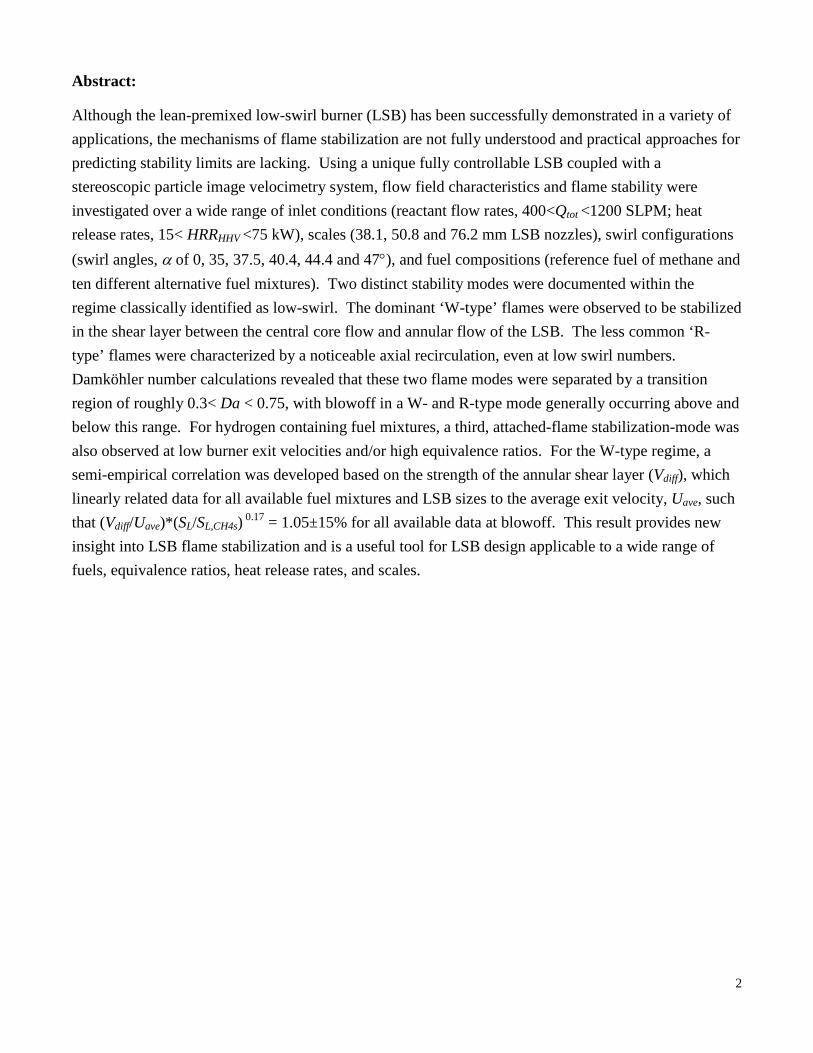
To explore the differences between the two apparent blowoff modes, PIV flowfield measurements were performed at conditions corresponding to the circles in Fig. 3b. As seen in Fig. 4a, the flame front for conditions near R-type blowoff exhibits a rounded tulip-like shape rather than an obvious W-shape, which sits lower than the typical flame. The flowfield contains some axial recirculation, and the strong in- and out-of plane swirling action of the flow is still evident downstream of the flame front, curling in radially toward the center of the flame. The flame front near W-type blowoff (Fig. 4b) is still not quite a typical ‘W’ shape, but it is wider and obviously further downstream than the flame front at R-type blowoff
conditions. The W-type blowoff flowfield does not show any explicit recirculation, but there is an obvious deceleration in terms of axial velocity along the slightly deflected centerline streamline.
From these and other PIV velocity field data not shown, it can be generally concluded that R-type blowoff is characterized by a combination of the swirling outer flow radially curling towards the center of the flame, a significant amount of axial recirculation downstream of the flame front, and a lower than typical flame front height at blowoff. The dominant W-type blowoff mode is characterized by the flame front stabilizing at a higher axial location and a tendency toward a recurrent ‘W’-shaped flame that is anchored along the shear layer between the inner core flow and outer annular flow. W-
7
type flames lack any significant axial recirculation within the flame zone, and the outer swirling motion diverges out radially as
opposed to curling in as in the R-type blowoff case.
Figure 4: Near blowoff for 38.1 mm LSB at Φ = 0.7 and HRRHHV = 40.8 kW for a) R-type flame, S = 0.66 b)
W-type flame, S = 0.55
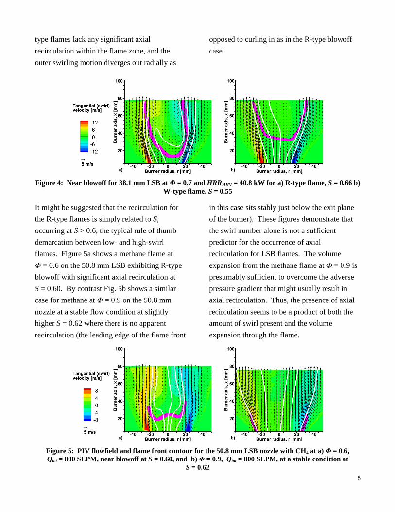
It might be suggested that the recirculation for the R-type flames is simply related to S, occurring at S > 0.6, the typical rule of thumb demarcation between low- and high-swirl flames. Figure 5a shows a methane flame at Φ = 0.6 on the 50.8 mm LSB exhibiting R-type blowoff with significant axial recirculation at S = 0.60. By contrast Fig. 5b shows a similar case for methane at Φ = 0.9 on the 50.8 mm nozzle at a stable flow condition at slightly higher S = 0.62 where there is no apparent recirculation (the leading edge of the flame front
in this case sits stably just below the exit plane of the burner). These figures demonstrate that the swirl number alone is not a sufficient predictor for the occurrence of axial recirculation for LSB flames. The volume expansion from the methane flame at Φ = 0.9 is presumably sufficient to overcome the adverse pressure gradient that might usually result in axial recirculation. Thus, the presence of axial recirculation seems to be a product of both the amount of swirl present and the volume expansion through the flame.
Figure 5: PIV flowfield and flame front contour for the 50.8 mm LSB nozzle with CH4 at a) Φ = 0.6, Qtot = 800 SLPM, near blowoff at S = 0.60, and b) Φ = 0.9, Qtot = 800 SLPM, at a stable condition at
S = 0.62 8

3.4 Stability Measurements with Alternative Fuels
Blowoff and flashback stability limits for the ten different alternative fuel mixtures summarized in Table 1 were also measured over a wide range of operating conditions using identical procedures as described above. These plots are included as supplementary material to this paper and discussed in greater detail in [16]. Results of these measurements show that that the LSB is amenable to multiple different fuel mixtures, in agreement with [10,11,15]. The main effects of varying fuel composition on stability are attributable to the enhancement of the laminar flame speed (SL) with increased hydrogen content of the fuel. As expected, increasing SL (via increasing Φ or %H2) makes the flame harder to blowoff, but easier to flashback (lower S at both limits), which is consistent with experimental findings that show that %H2 in the fuel mixture is a key parameter influencing blowoff characteristics of syngas flames [17–20]. PIV measured flowfields for all of the tested alternative fuel mixtures showed exclusively W-type blowoff properties, except in cases where a third attached-flame stable operating mode was observed.
For the H2 containing fuels considered, if the average exit velocity, Uave, was lowered (by lowering Qtot at constant S), the flame position would lower until eventually the flame would stably attach to exit nozzle of the LSB. Although the flame could be lifted again by raising Uave, once attached it was not possible to induce blowoff by lowering the S (although raising S would still eventually induce
flashback). With higher Φ and/or %H2 this occurred at higher Uave, similar to the recent findings of Cheng and coworkers [4,11]. A linear relation was found between Uave at flame attachment and SL of the hydrogen-containing fuel mixtures [16], showing as expected that SL is a critical factor in determining the attached flame mode. However, in separate experiments where SL, S, and Uave were held constant among different fuel mixtures (S1, S2, S3, and methane with 50%, 37.5%, 25%, and 0% hydrogen respectively), both S3 and S2 stabilized in the attached flame mode, while S1 and methane stabilized as lifted shear-layer stabilized flames. This led to the conclusion that while SL is important for the attached flame, the unique properties of hydrogen are also a factor. Kido et al.[21] present data showing that hydrogen-containing mixtures have a higher sensitivity to turbulent fluctuations as measured in their turbulent flame speeds. Although this was explored via turbulent flame speed measurements using the local displacement method as presented in [22], it was not possible to discern an enhanced sensitivity in the present data.
3.5 Damköhler Numbers Near Blowoff
As summarized in [23], most studies on developing blowoff correlations for premixed gases relate the blowoff conditions to a Damköhler number (Da) (e.g. [19,20]). Such an approach was attempted with the present data using a representative Damköhler number defined as Da = (l0/u’rms)/(α/SL
2) where l0 is the integral length scale in the axial direction (calculated from cross-correlation of
9

instantaneous PIV flowfields), u’rms is the axial RMS turbulence fluctuation from the PIV flowfields, and α is the thermal diffusivity of the fuel/air mixture. For the present analysis, α was calculated from simulations of premixed 1D laminar flames courtesy of Abhishek Barnwal at the University of Toronto performed using Cantera software. A representative thermal diffusivity of the reacting mixture was calculated at the center of the spatial range of the simulation between pure products and pure reactants. Further details of the data used in Da calculations are included as supplementary material to this manuscript.
The Damköhler number at the leading edge of the flame was measured for five near-R-type blowoff conditions (all methane fuel, where R-type blowoff was observed), and 33 near-W-type blowoff conditions (methane fuel and bio- and syn-gas mixtures). The results show that the Da near W-type blowoff is relatively higher at the leading edge of the flame as compared to near-R-blowoff. In the four cases where the flowfield properties suggested a W-type blowoff mode, but the measured Da was relatively low, closer inspection of the PIV velocity field data suggested that these conditions were indicative of a transition between the two stability modes in which the flame is just barely able to anchor along the shear-layer to produce a W-type flame, but flow recirculation is beginning to appear and the timescale of the chemistry is apparently slow relative to the turbulence in the shear layer. Based on the available data, it appears that the transition between R- and W-type stability modes occurs roughly in the range of 0.3 < Da < 0.75, with R-type generally below
this region, and W-type generally above. It is noted that calculating Da using either the integral length scale or RMS turbulence fluctuation in other directions (radial and/or tangential) produced a change in the absolute values of Da (due to anisotropic turbulence consistent with [10]), but the same separating effect between R- and W-type blowoff was still present.
3.6 Semi-Empirical Correlation
Mansour and Chen [24] recently suggested a simple blowoff correlation for methane/air jet-type LSB flames in which they observed UD/u = 5.08 mm at blowoff conditions, where U refers to the central jet velocity, D refers to the burner diameter, and u is the tangential jet velocity. This can be extended to a vane-type LSB, where the burner diameter at the location of the central nonswirling jet (D) in Mansour and Chen (2008) is equivalent to the inner flow diameter (0.8 x the outer diameter) in the vane-type LSB; the central jet velocity, U, is equivalent to the inner flow velocity; and the tangential jet velocity, u, is equivalent to the outer flow exit velocity including the tangential component, which is calculated as u = [Uo,x
2 + (Uo,xtan(α))2]1/2. Uo,x is the outer axial velocity (measured as outer flow rate divided by outer area), and α is the vane exit-angle (this assumes there is no fluid deviation from this angle).
Figure 6 tests the Mansour and Chen [24] correlation with methane-only blowoff curves for the three LSB nozzle sizes. While the correlation clearly does not align with the present data, there is a common linear trend for
10

the majority of the 38.1 mm and 50.8 mm LSB data. The 76.2 mm LSB data also show a linear trend but with a different slope than the 38.1 mm and 50.8 mm data. It is noteworthy, however, that for the 38.1 mm and 50.8 mm LSB data, exceptions to the common linear trend were previously identified as R-type rather than W-type blowoff conditions.
Figure 6: Comparison of methane blowoff curves
to Mansour and Chen [24] correlation
All of the results presented in this paper highlight the importance of the annular shear layer in determining flame stability, especially for flames in a W-type mode (shear layer stabilized flames). The strength of the 3D shear layer is a function of the magnitude of the velocity vector difference between the inner core flow and outer annular flows,
𝑉𝑑𝑖𝑓𝑓 = ��𝑈𝑜,𝑥 − 𝑈𝑖,𝑥�2
+ �𝑈𝑜,𝑥 tan(𝛼)�2�1/2
,
where Ui,x is the inner axial velocity. Drawing on this concept, all W-type blowoff limit data available in this study were plotted as shown in Fig. 7. A remarkably tight correlation is apparent, which underscores the importance of the strength of the 3D shear layer in determining LSB flame stability. This is especially true
given that the plotted data include blowoff data from all three LSB diameters, all eleven fuel mixtures, all Φ, and all swirl angles (including the non swirling outer flow case for the 50.8 mm LSB). The horizontal axis of Fig. 7 includes a slight empirical scaling of Vdiff by (SL/SL,CH4s)0.17 to account for the minor spread of the data associated with the different fuel types, and it is notable that the correlation coefficient without this scaling is still R2 = 0.974.
Given the linear trend in Fig. 7, a single non-dimensional blowoff stability parameter can be defined as BP=(Vdiff /Uave)*(SL/SL,CH4s)0.17, where all available data fall within approximately ±15% of BP=1.05. This parameter effectively summarizes key observed behavior of the LSB in a W-type stabilization mode. With increasing average exit velocity (due to smaller diameter nozzle or increased flowrate), the shear layer strength needed to stabilize the flame increases, and fuel/air mixtures with higher SL require slightly less shear layer strength to remain stable (at a constant Uave). The correlation presented in Fig. 7 provides a useful design tool for determining whether a flame will blow off or not for a given fuel mixture, equivalence ratio, average exit velocity, and strength of the 3D shear layer within the LSB. This result also demonstrates that the LSB is extremely fuel flexible so long as the attached flame mode is avoided (i.e. by limiting the H2 content of the fuel or by increasing the exit velocity of the reactants accordingly) and the swirl number is kept sufficiently low and/or equivalence ratio is kept sufficiently high to avoid R-type blowoff. Otherwise, the open- atmosphere LSB requires
11

no significant redesign to implement the tested syngas and biogas fuels immediately.
Figure 7: Semi-empirical correlation for LSB
blowoff (W-type blowoff only) for all fuel mixtures, all Φ, all nozzle diameters, all swirl
angles (including non-swirling case for 50.8 mm nozzle)
4. Conclusions
Using a unique fully controllable low-swirl burner, blowoff and flashback stability limits were measured for a wide parametric range of heat release rates, equivalence ratios, swirl numbers and burner scales using 11 different biogas and syngas fuel mixtures. Two distinct flame stabilization modes were observed within the regime classically labelled low-swirl. The dominant W-type blowoff mode was characterized by a W-shaped flame that stabilized in the shear layer between the inner non-rotating core flow and annular swirling flow. The secondary R-type blowoff mode was characterized by a weak tulip-shaped flame stabilized by a weak central recirculation zone. A third attached flame mode was observed with certain hydrogen-containing fuel mixtures that was closely correlated with the laminar flame
speed of the fuel mixture. The differentiation between the W- and R-type stability modes was related to a Damköhler number evaluated at the flame front implying chemically limited blowoff for the R-type flames with a transition between the two modes occurring at roughly 0.3 < Da < 0.75. If an attached flame is to be avoided when hydrogen is present in the fuel mixture, then the equivalence ratio must be kept low, the flowrate must be raised, or a combination of these two strategies must be employed.
Recognizing the importance of the annular shear-layer strength in determining flame stability, for the dominant W-type flames (including transitional W-type flames), a semi-empirical parameter was developed that successfully correlated blowoff data for all nozzle diameters, flow rates, swirl angles (including no-swirl), and fuel mixtures. Blowoff data were linearly related to the average exit velocity, Uave, such that (Vdiff/Uave)*(SL/SL,CH4s)
0.17 = 1.05±15% for all data at W-type blowoff, with stable flames existing at values above this threshold. This result provides a useful tool for LSB design that is applicable to a wide range of fuels, equivalence ratios, heat release rates, and scales.
5. Acknowledgements
This project was supported by the Natural Sciences and Engineering Research Council (NSERC) and Rolls-Royce Canada. We are indebted to Brian Crosland, Ian Joynes, Stephen Schoonbaert, Gustavo Strahman and Patrizio Vena of the Energy & Emissions Lab at Carleton University for their assistance with the experiments.
12

6. References
[1] C.K. Chan, K.S. Lau, W.K. Chin, R.K. Cheng, P. Combust. Inst. 24 (1992) 511-518.
[2] D.T. Yegian, R.K. Cheng, Combust. Sci. Technol. 139 (1998) 207-227.
[3] R.K. Cheng, Combust. Flame 101 (1995) 1-14.
[4] R. Cheng, D. Littlejohn, in:, Proceedings of the ASME Turbo Expo 2008, ASME, Berlin, Germany, 2008, pp. 393-407.
[5] M.R. Johnson, D. Littlejohn, W.A. Nazeer, K.O. Smith, R.K. Cheng, P. Combust. Inst. 30 (2005) 2867-2874.
[6] M. Legrand, J. Nogueira, A. Lecuona, S. Nauri, P. a. Rodríguez, Exp. Fluids 48 (2010) 901-913.
[7] K.-J. Nogenmyr, P. Petersson, X.S. Bai, C. Fureby, R. Collin, a. Lantz, M. Linne, M. Aldén, P. Combust. Inst. 33 (2010) 1567-1574.
[8] J.G. Strahman, Flame Stability of an Ultra-Lean Premixed Low-Swirl Burner, M.A.Sc. Thesis, Carleton University, 2007.
[9] T. Lieuwen, V. McDonell, D. Santavicca, T. Sattelmayer, Combust. Sci. Technol. 180 (2008) 1169-1192.
[10] D. Littlejohn, R.K. Cheng, P. Combust. Inst. 31 (2007) 3155-3162.
[11] R.K. Cheng, D. Littlejohn, P.A. Strakey, T. Sidwell, P. Combust. Inst. 32 (2009) 3001-3009.
[12] T. Lieuwen, V. McDonell, E. Petersen, D. Santavicca, J. Eng. Gas Turbines Power 130 (2008) 011506-1-8.
[13] R.K. Cheng, D. Littlejohn, J. Eng. Gas Turbines Power 130 (2008) 9.
[14] R. Cheng, D. Littlejohn, W. Nazeer, For Gas Turbines And (2008).
[15] D. Littlejohn, R.K. Cheng, D.R. Noble, T. Lieuwen, J. Eng. Gas Turbines Power 132 (2010) 011502-1-8.
[16] G.E. Ballachey, Analysis of Blowoff in a Low-swirl Burner: Effect of Burner
Geometry and Fuel Composition, M.A.Sc. Thesis, Carleton University, Ottawa, Canada, 2011.
[17] R. Schefer, Int. J. Hydrogen Energy 28 (2003) 1131-1141.
[18] C. Vagelopoulos, F. Egolfopoulos, in:, Symposium (International) on Combustion, Elsevier, 1994, pp. 1317–1323.
[19] D.R. Noble, Q. Zhang, A. Shareef, J. Tootle, A. Meyers, T. Lieuwen, in:, Proceedings of ASME Turbo Expo, Barcelona, Spain, 2006, pp. 1-12.
[20] Q. Zhang, Lean Blowoff Characteristics of Swirling H2/CO/CH4 Flames, Ph.D. Thesis, Georgia Institute of Technology, 2008.
[21] H. Kido, M. Nakahara, K. Nakashima, J. Hashimoto, P. Combust. Inst. 29 (2002) 1855-1861.
[22] R.K. Cheng, in:, T.C. Lieuwen, V. Yang, R.A. Yetter (Eds.), Synthesis Gas Combustion: Fundamentals and Applications, CRC Press, Taylor & Francis Group, Boca Raton, FL, 2010, pp. 129-168.
[23] I. Glassman, R. Yetter, Combustion, 4th ed., Academic Press, Amsterdam; Boston, 2008.
[24] M. Mansour, Y.-C. Chen, Exp. Thermal Fluid Sci. 32 (2008) 1390-1395.
13