
Prediction and Analysis of Polished Rod Dynamometer Card...
11
Research Article Prediction and Analysis of Polished Rod Dynamometer Card in Sucker Rod Pumping System with Wear Dongyu Wang and Hongzhao Liu School of Mechanical and Precision Instrument Engineering, Xi’an University of Technology, Xi’an 710048, China Correspondence should be addressed to Hongzhao Liu; [email protected] Received 4 July 2018; Revised 21 September 2018; Accepted 2 October 2018; Published 1 November 2018 Academic Editor: Jos´ e J. Rangel-Magdaleno Copyright © 2018 Dongyu Wang and Hongzhao Liu. is is an open access article distributed under the Creative Commons Attribution License, which permits unrestricted use, distribution, and reproduction in any medium, provided the original work is properly cited. In the oil production process, the wear of friction pairs in sucker rod pumping installations will increase over time, which leads to the failure of the sucker rod pumping system. In order to study the effect of wear on the sucker rod pumping system, a wear model between the plunger and pump barrel was established. By analyzing the wear law, the wear volume and wear time of the pump barrel were calculated under abrasive wear. e forces of the sucker rod microunit were analyzed, and the wave equation of the sucker rod was established. Based on the given boundary and initial conditions, a mixed difference method was used to solve the equation. Taking the no. L2111 well of an oilfield as an example, the change curves of the wear volume and wear time with abrasive particle diameter were plotted, and the polished rod dynamometer card considering wear was predicted. e results showed that the increased clearance caused by wear will reduce the polished rod load on upstroke of the sucker rod pumping system, which could provide a theoretical basis for the next fault diagnosis. 1. Introduction e petroleum industry plays an important role in the con- tinuous development of the national economy. e state has attached great importance to the petroleum industry and issued the 13th five-year plan for oil development in 2016 [1]. e process of petroleum exploration, mining, processing, and exploitation are the key activities of the petroleum industry. At present, the use rod pumping equipment is the main means of oil recovery, among which the pumping unit is one of the main working parts. Among the parameters of the pumping unit, the polished rod load is the most common and most important. e polished rod dynamometer card is an image describing the change in the polished rod load with polished rod displace- ment. It not only reflects the downhole working conditions of the beam pumping unit [2] but also calculates the balance of the pumping unit, reducer output shaft torque, and motor power [3, 4]. At the same time, the actual polished rod dy- namometer card can be matched with the fault cards, which are often used to diagnose the fault of the oil well [5–11]. us, it is very meaningful to study the polished rod load. First, the approximate formula was used to calculate the polished rod load of pumping units. For example, only the gravity of the rod string in the air and the buoyancy of liquid to the rod string were considered. e most common method is the API method [12] published by the American Petroleum Institute. e results of the method were com- pared with the results measured from 77 wells in the field, and the results are relatively accurate. In 1963, Gibbs [13] introduced the prediction model of the sucker rod pumping system, which laid the theoretical foundations for the ac- curate design of sucker rod pumping systems. A one- dimensional wave equation with damping was established in the prediction model, along with the boundary conditions and initial conditions of the rod and pump. e finite difference method was used to solve the wave equation, and the rod dynamometer card in any section can be drawn accurately. Later, Gibbs [14] summarized the methods for the design and analysis of rod pumping installations and applied the wave equation to the fault diagnosis of the sucker rod pumping system. In 1983, Doty and Schmidt [15] presented a two-dimensional model for predicting the Hindawi Shock and Vibration Volume 2018, Article ID 4979405, 10 pages https://doi.org/10.1155/2018/4979405
Transcript of Prediction and Analysis of Polished Rod Dynamometer Card...
Research ArticlePrediction and Analysis of Polished Rod Dynamometer Card inSucker Rod Pumping System with Wear
Dongyu Wang and Hongzhao Liu
School of Mechanical and Precision Instrument Engineering Xirsquoan University of Technology Xirsquoan 710048 China
Correspondence should be addressed to Hongzhao Liu liu-hongzhao163com
Received 4 July 2018 Revised 21 September 2018 Accepted 2 October 2018 Published 1 November 2018
Academic Editor Jose J Rangel-Magdaleno
Copyright copy 2018 Dongyu Wang and Hongzhao Liu is is an open access article distributed under the Creative CommonsAttribution License which permits unrestricted use distribution and reproduction in anymedium provided the original work isproperly cited
In the oil production process the wear of friction pairs in sucker rod pumping installations will increase over time which leads tothe failure of the sucker rod pumping system In order to study the effect of wear on the sucker rod pumping system a wear modelbetween the plunger and pump barrel was established By analyzing the wear law the wear volume and wear time of the pumpbarrel were calculated under abrasive wear e forces of the sucker rod microunit were analyzed and the wave equation of thesucker rod was established Based on the given boundary and initial conditions a mixed difference method was used to solve theequation Taking the no L2111 well of an oilfield as an example the change curves of the wear volume and wear time with abrasiveparticle diameter were plotted and the polished rod dynamometer card considering wear was predicted e results showed thatthe increased clearance caused by wear will reduce the polished rod load on upstroke of the sucker rod pumping system whichcould provide a theoretical basis for the next fault diagnosis
1 Introduction
e petroleum industry plays an important role in the con-tinuous development of the national economy e state hasattached great importance to the petroleum industry andissued the 13th five-year plan for oil development in 2016 [1]e process of petroleum exploration mining processing andexploitation are the key activities of the petroleum industry Atpresent the use rod pumping equipment is the main means ofoil recovery among which the pumping unit is one of themainworking parts Among the parameters of the pumping unit thepolished rod load is the most common and most importante polished rod dynamometer card is an image describing thechange in the polished rod load with polished rod displace-ment It not only reflects the downhole working conditions ofthe beam pumping unit [2] but also calculates the balance ofthe pumping unit reducer output shaft torque and motorpower [3 4] At the same time the actual polished rod dy-namometer card can bematchedwith the fault cards which areoften used to diagnose the fault of the oil well [5ndash11]us it isvery meaningful to study the polished rod load
First the approximate formula was used to calculate thepolished rod load of pumping units For example only thegravity of the rod string in the air and the buoyancy of liquidto the rod string were considered e most commonmethod is the API method [12] published by the AmericanPetroleum Institute e results of the method were com-pared with the results measured from 77 wells in the fieldand the results are relatively accurate In 1963 Gibbs [13]introduced the prediction model of the sucker rod pumpingsystem which laid the theoretical foundations for the ac-curate design of sucker rod pumping systems A one-dimensional wave equation with damping was establishedin the prediction model along with the boundary conditionsand initial conditions of the rod and pump e finitedifference method was used to solve the wave equation andthe rod dynamometer card in any section can be drawnaccurately Later Gibbs [14] summarized the methods forthe design and analysis of rod pumping installations andapplied the wave equation to the fault diagnosis of the suckerrod pumping system In 1983 Doty and Schmidt [15]presented a two-dimensional model for predicting the
HindawiShock and VibrationVolume 2018 Article ID 4979405 10 pageshttpsdoiorg10115520184979405
behavior of sucker rod pumping installations e modelconsidered the dynamics of the fluid and tubing columns aswell as the physical properties of the fluid is provideda new way of analyzing the effects of fluid properties ona sucker rod pumping installation In 1992 Wang et al [16]proposed the three-dimensional vibration of the sucker rodtubing and liquid column in the sucker rod pumpingsystem e results indicated that the new model is animprovement over existing one-dimensional and two-dimensional models
Since the twentieth century studies on polished rod loadhave focused on two aspects e first is a new research objectIn order to reduce the polished rod load Luan et al [17]presented a side-flow pump which offered the possibility ofdeeper setting depth of the pump in oil wells and could be usedin deep well sucker rod pumping Rotaflex is a completelymechanical long-stroke pumping unit For the first timeTakacs [18] conducted a thorough investigation of the kine-matic performance of Rotaflex pumping units and developedexact formulas for the calculation of polished rod positionvelocity acceleration and load According to the demand foroffshore heavy oil thermal recovery and the production ofstripper wells Yu et al [19] designed a newminiature hydraulicpumping unit with long stroke low pumping speed andcompact structure to resolve the problem of limited spacerough the establishment of the mechanical model for rodsthe polished rod load was calculated e smooth operation ofthe prototype verified the practicality and effectiveness of theoverall design scheme and laid the foundations for field testingRecently Liu et al [20ndash22] conducted a series of experimentson a coalbed methane (CBM) well A modern methodologywas proposed for the system design of dynamic behavior toconduct accurate and pertinent analysis of CBM pumpinginstallations rough the establishment of the model thepolished rod load was accurately predicted e second aspectis a new research method Gong et al [23] proposed a pre-dictive algorithm based on a least squares support vectormachine model and applied it to oil pumping wells Li et al[24] established a coupled dynamic model for describing thedynamic performance of the polished rod load of beampumping units e oilfield application showed the effective-ness and accuracy of the new model which could be used topredict operating parameters such as load pump efficiencytorque and balance as well as in-fault diagnosis Feng et al[25] developed a set of rated power calculation methods anda set of matching templates with the intention of improving theefficiency of the prime motor and decreasing the cost of rodpumping e tested data showed that the polished rod loaddecreased substantially Chen et al [26] developed an optimalcontrol approach for predicting the behavior of sucker rodpumping systems e method provided error correction inpredictions and generated accurate polished rod andintermediate-depth work dynagraphs for any bottom-holepump condition in vertical oil wells
In the actual pumping process wear develops between theplunger and pump barrel of the oil pump but previous pre-diction models failed to consider the effects of wear In thevibrationmodel of the rod string the real factors that influencethe downstroke boundary conditions have also increased
erefore a wear model between the plunger and pump barrelis established and the wear mechanism between the plungerand pump barrel is studied e wave equation of the suckerrod string is developed and the upper and downhole boundaryconditions are determined as well as the initial conditionsTaking the clearance between the plunger and pump barrel asa parameter the effects of clearance caused by wear on thepolished rod dynamometer card is analyzed
2 Wear Modeling of Plunger-Pump Barrel
e wear of friction pairs in the plunger-pump barrel willcause the failure of the sucker rod pumping system a processthat involves adhesive wear abrasive wear and corrosionwear Since the system is assembled with clearance betweenthe plunger and pump barrel the presence of crude oil in theclearance between the plunger and pump barrel acts asa lubricant e wear of plunger-pump barrel increases withhigh sand content high water content and incorrect com-bination of the plunger and pump barrel in the oilfieldSpecifically a large amount of sand will enter the wedgeclearance with increasing the sand content and the surfacesof the plunger and pump barrel are vulnerable to wear elubrication performance of oil-water mixtures is greatlyreduced with increasing water content e coefficient offriction between the plunger and pump barrel also increaseswhich accelerates the wear of the plunger When theclearance is too small adhesive wear occurs on the contactsurfaces of the plunger and pump barrel owing to the lack oflubrication In addition corrosion occurs at the contactsurfaces between the plunger and pump barrel in acid alkalisalt and other special medium Bu [27] pointed out that themain component of pump wear was sand erefore thewear type between the plunger and pump barrel is identifiedonly as abrasive wear in this study
In order to facilitate the establishment of the wear modelthe following assumptions are made
(1) It is assumed that wear only occurs on the pumpbarrel instead of the plunger and abrasive
(2) e radial load of abrasive particles from the pumpbarrel is defined as the average value of radial loadson the upstroke and downstroke
(3) e abrasive particle is spherical with a specific di-ameterWhen the clearance between the plunger andpump barrel is larger than the diameter of theabrasive particle the abrasive particle falling into thepump will not cause wear on the barrel Largerabrasive particles continue to wear on the pumpbarrel and the wear process will continue the wearlimit is reached
It is assumed that the diameter of the first abrasiveparticle is D1 the diameter of the second one is D2 and thediameter of the nth one is Dn erefore
D1 minus δ1 D2 minusD1 Dn minusDnminus1 δ (1)
where δ1 is the initial fit clearance of the plunger and pumpbarrel δ is the radial wear depth of the abrasive particle andδ 10minus2δ1
2 Shock and Vibration
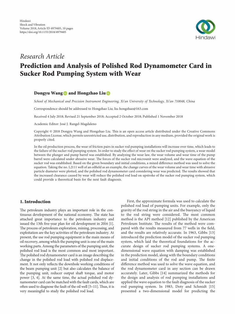
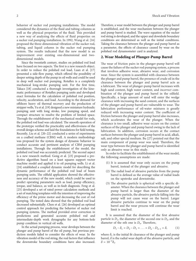
Taking a single abrasive particle as the object ofstudy mechanical analysis of the abrasive particle wascarried out during the upstroke and downstroke whichare shown in Figures 1 and 2 Based on the mechanicalanalysis the mechanical models of the abrasive particle areestablished
In Figures 1 and 2 NBu and NBd are the radial forces ofthe pump barrel Npu and Npd are the support forces of theplunger FBu and FBd are the friction of the pump barrel andFPu and FPd are the friction of the plunger on the upstrokeand downstroke G is the gravity of the abrasive particle andθ is the angle between the plumb line and chamfer surface ofthe plunger Combined with the forces acting on the abrasiveparticle in Figures 1 and 2 the following equations can beobtained
On the upstroke
NBu minusNPu cos θ + FPu sin θ 0
NPu sin θ + FPu cos θminusFBu minusG 0(2)
On the downstroke
NBd minusNPd cos θminusFPd sin θ 0
NPd sin θ + FPd cos θminusFBd minusG 0(3)
In Equations (2) and (3) the friction force is equal to thepressure multiplied by the friction coefficient is meansthat FBu μmiddotNBu FBd μmiddotNBd FPu μmiddotNPu and FPd μmiddotNPdwhere μ is the friction coefficient It is obvious that NBu andNBd can be determined by simplifying Equations (2) and (3)
Based on the energy wear theory [28] the computationalmodel for determining the wear volume of the pump barrelunder the action of the i-th abrasive particle is established asfollows
Vi Q
HPiLi (4)
whereQ is the coefficient of wearH is the Brinell hardness ofpump barrel material Li is the friction distance of the i-thabrasive particle to the pump barrel and Pi is the radial forceof the i-th abrasive particle to the pump barrel
According to the model assumptions the radial force ofthe i-th abrasive particle to the pump barrel is calculated bythe following formula
Pi NBu(i) + NBd(i)
2 (5)
whereNBu(i) andNBd(i) are the values ofNBu andNBd at the i-th abrasive particle
In Equation (4) Q and H are known in the calculationprocess In order to study Li the wear volume Vi should becalculated first According to the actual wear condition ofthe pump barrel the geometric model of abrasive wearbetween plunger and pump barrel is established as shownin Figure 3
As can be seen in Figure 3 the area of the AECD is thewear area of the abrasive particle and pump barrel e keyto calculating the wear volume is to acquire the area of theAECD According to the geometric relationship the area
of AECD can be obtained as shown in the followingequation
SAECD SO1ADCminus SO1AEC SO1ADCminus SO1ABCminus SABEC
SO1ADCminus SO1ABCminus SOAEC + SOABC(6)
where S denotes the areaFor the i-th abrasive particle O1ADC and OAEC are
sectors while O1ABC and OABC are triangles According tothe corresponding area calculation formula the areas ofO1ADC OAEC O1ABC and OABC are calculated UsingEquation (6) the wear area of the i-th abrasive particle Si canbe obtained As the pump is a reciprocating mechanism thewear volume of the pump barrel is equal to the wear areamultiplied by the pump strokeat isVi smiddotSi where s is thepump stroke
In Equation (4) Li is a function of time which is writtenas
Li 288 times 103sNTi (7)
Abrasive particle
Plunger
h
G
NBu
NPu
FPu
FBu
Pump barrel
θ
δ1δmax
Figure 1 e forces of the abrasive particle on upstroke
h
G
FBd
FPd
NPd
NBd
Abrasive particle
Plunger
Pump barrel
θ
δ1δmax
Figure 2 e forces of the abrasive particle on downstroke
Shock and Vibration 3
where N is the pump speed and Ti is the wear time of thei-th abrasive particle erefore according to Equations (4)and (7) the wear time of the i-th abrasive particle can beobtained
3 Vibration Modeling of the Rod String
31MechanicalAnalysis of theRodString In order to analyzethe forces of the sucker rod the microunit of the sucker rodis taken as a research object e forces of the microunitinclude the axial force of the microunit acting on the uppercross section and lower cross section (F(xt) and F(x+Δxt))the inertia force of the microunit (Fa) the viscous force andsupport reaction force acting on the microunit (Frl and N)the frictional force between the tubing and sucker rod (Frt)and gravity of the sucker rod (Wr) e forces are applied asshown in Figure 4
e mechanical analysis process is simplified and thewave equation of the sucker rod is obtained by referring toprevious study [29]
z2u
zt2 a
2z2u
zx2 minus czu
ztminus δhN + gprime cos θ (8)
where a Erρr
1113968 c ]eρrAr h fρrAr and gprime ρr
primegρrIn Equation (8) u(xt) is the displacement along the
depth direction in position x of the sucker rod at time t Er isthe modulus of elasticity of the sucker rod and ρr is suckerrod density ]e is the viscous damping coefficient per unitlength of the sucker rod and Ar is the cross-sectional area ofthe sucker rod δ determines the direction of the force and isequal to minus1 if the sucker rod is operating on the upstrokeotherwise it is equal to +1 f is the friction coefficient betweenthe tubing and sucker rod N is the support reaction forceacting on the microunit from the tubing ρprimer is the relativedensity of the sucker rod in oil and g is the acceleration ofgravity
32 Upper Boundary Condition In order to solve the waveequation of the sucker rod the upper boundary conditionneeds to be given first In fact the upper boundary con-dition is the upper endpoint movement of the sucker rodwhich is the same as the displacement of the polished rodat is
u(0 t) U0 (9)
where u(0t) is the value of u(xt) at x 0 and U0 is thepolished rod displacement
e displacement of the polished rod was obtainedby studying the motion law of the pumping unit Inone pumping process the rotation of the crank leadsthe movement of the walking beam which drives horsehead moving from the down-fixed point to the up-fixedpoint and then moving to the down-fixed point Figure 5is a sketch of the mechanism of the conventional beampumping unit It can be seen that ψ is the angle betweenC and K where C is the back-arm length of the beam andK is the distance between the support center of the beamand the output shaft center of the gear reducer When thehorse head is at the down-fixed point the angle ψ is definedas ψb When the horse head is at the up-fixed point theangle ψ is defined as ψt According to the triangle cosinetheorem these two angles can be obtained
ψb arccosC2 + K2 minus(P + R)2
2CK1113888 1113889
ψt arccosC2 + K2 minus(PminusR)2
2CK1113888 1113889
(10)
where P is the length of pitman arm and R is the radius of thecrank
erefore the calculation formula of the polished roddisplacement of the pumping unit can be given as
F(x + Δxt)
N
φ
x(N)
y(E)
F(xt)
Z (Down)
Fa
Wr
FrlFrt
α
Figure 4 Force schematic diagram of the sucker rod microunit
O
O1
θ1
AB
C
D
θ2
E
Barrel
Plunger
Abrasiveparticle
Figure 3 e geometric model of abrasive wear
4 Shock and Vibration
U0 ψb minusψψb minusψt
s (11)
where s is the polished rod stroke After determining the typeof the pumping unit the geometric parameters of thepumping unit are obtained Substituting the values of ψt andψb calculated by geometric parameters in Equation (11) thepolished rod displacement of the pumping unit is obtained
33 Downhole Boundary Conditions e downholeboundary conditions refer to the relationship between theload acting on the plunger and plunger displacement edownhole boundary conditions [29] can be written asfollows
αu(L t) + βzu(L t)
zx+ c
z2u(L t)
zt2+ κ
zu(L t)
zt p(t)
(12)
In Equation (12) the second term represents the liquidload acting on the plunger on upstroke e third termrepresents the liquid inertial load acting on the upper part ofthe plunger on upstroke When the plunger is in the ac-celeration section of upstroke c is the liquid mass on theupper part of the plunger When the plunger is in the de-celeration section of upstroke or downstroke c is equal tozero e fourth term represents the frictional force betweenthe plunger and pump barrel e κ in the formula is de-termined by the following expression
κ 2πμLp lnRp
Rb1113888 1113889 (13)
where μ is the dynamic viscosity of the well liquid and Lp Rpand Rb are the plunger length plunger radius and barrelrespectively
In actual production when the oil pump is in differentstages the values of α β and p(t) are different By judgingthe opening and closing of the standing valve and travelingvalve in the oil pump the values of α β and p(t) are de-termined and the downhole boundary conditions of thesucker rod pumping system are calculated
34 Initial Conditions When solving Equation (8) theinitial condition must first be given As the vibration of thesucker rod string is forced vibration with damping it canassume any initial condition In order to facilitate thesimulation of downhole boundary conditions the followinginitial conditions can be adopted Assuming that the electricmotor starts at t 0 the polished rod is at the down-fixedpoint At t 0 the whole sucker rod string is at the stationarystate which means that
u(x 0) 0
uprime(x 0) 0(14)
where u(x 0) is the value of u(x t) at t 0 and uprime(x 0) is thepartial derivative value of u(x t) to t at t 0
4 The Establishment of a MixedDifference Scheme
In this study the finite difference method was used toapproximate Equation (8) e calculation process of ex-plicit difference is simple but the convergence condition isstrong For the purpose of overcoming the limitations ofthe convergence condition and speed using the explicitdifference format the implicit difference format waschosen to approximate Equation (8) Owing to the complexand changeable underground structure a multistage rodwas used for oil recovery When an equal step difference isused to establish a difference scheme for the multistage rodthe density elastic modulus etc need to be homogenizedfirst As the ratios of various types of sucker rods areuncertain the accuracy of the calculation is difficult toguarantee In order to overcome the above shortcomingsthe multistage rod is considered as multiple homogeneousrods A three-storey implicit difference format was adoptedfor the homogeneous rod and variable step-length dif-ference was adopted between different adjacent homoge-neous rods
41 Difference Scheme of Homogeneous Rod In the homo-geneous rod Δx is selected as the node of equal step alongthe axial direction of the sucker rod en the sucker rod isdivided into m units and i is the subscript notation i 1 2 m Δt was selected as the node of equal step along thetime direction and j is the subscript notation j 1 2 nus uij represents the i node displacement of the rod stringat j time
In the node (i j) central difference quotient formulaswere selected to approximate zuzt and z2uzt2 whichmeans that
IG
Hθ0
C Aψb
ψ ψt
R
K
J
P
0prime
Figure 5 Sketch of the mechanism of the conventional beampumping unit
Shock and Vibration 5
zu
zt1113888 1113889
ij
uij+1 minus uijminus1
Δt (15)
z2u
zt21113888 1113889
ij
uij+1 + uijminus1 minus 2uij
Δt2 (16)
Furthermore the weighted average formula of centraldifference quotient in jminus1 j and j+1 layers was chosen toapproximate z2uzx2
z2u
zx21113888 1113889ij
ηui+1j+1 + uiminus1j+1 minus 2uij+1
Δx2
+(1minus 2η)ui+1j + uiminus1j minus 2uij
Δx2
+ ηui+1jminus1 + uiminus1jminus1 minus 2uijminus1
Δx2
(17)
where η is the weighted coefficient In order to facilitate thecalculation it is defined that η 12
By combining Equations (15)ndash(17) with (8) Equation (8)can be simplified as
minusa2
4Δx2uiminus1j+1 +a2
2Δx2 minusc
2Δtminus
1Δt2
1113888 1113889uij+1 +a2
4Δx2ui+1j+1
2a1 ui+1j minus uiminus1j1113872 1113873 + a2uij + a1 ui+1jminus1 minus uiminus1jminus11113872 1113873
+ a3uijminus1 minus bij
(18)
where
a1 minusa2
4Δx2
a2 minusa2
Δx2 +2Δt2
a3 minusa2
Δx2 minusc
2Δt
bij δijhiNij minusgjprime cos θ
(19)
In Equation (18) uiminus1j+1 uij+1 and ui+1j+1 on the leftside of the equal sign are unknown quantities that need to besolved by simultaneous equations is is a three-storeyimplicit difference format as shown in Figure 6
42 Difference Scheme of the Connection between Two Ho-mogeneous Rods A two-stage rod was selected as an ex-ample Δx1 is defined as the axial step of the firsthomogeneous rod while Δx2 is defined as the axial step ofthe second homogeneous rod as shown in Figure 7According to Equation (8) the wave equations of two dif-ferent homogeneous rods can be obtained
z2u
zt2 a
2l
z2u
zx2 minus cl
zu
ztminus δhlN + gl
prime cos θ (20)
where l is equal to 1 or 2In Figure 7 the differential formats of the wave equations
in each node are the same as Equation (18) except node i Innode i the continuity conditions of force F(i j) and dis-placement u(i j) should be satisfied at is
F(i j)1 F(i j)2 middot u(i j)1 u(i j)2 (21)
en Equation (21) is combined with the Taylor formulato obtain
zu
zx1113888 1113889
i1
uij minus uiminus1j
Δx1+
z2u
zx21113888 1113889i1
12Δx1 (22)
zu
zx1113888 1113889
i2
ui+1j minus uij
Δx2+
z2u
zx21113888 1113889i2
12Δx2 (23)
With the combination of Equations (20) to (23) thedifference equation of different materials in the connectionof different diameter rods is expressed by
Known point
Unknown point
i + 1 j
i ndash 1 j
i + 1 j + 1i + 1 j ndash 1
i ndash 1 j ndash 1 i ndash 1 j + 1
i j + 1i j ndash 1i j
Figure 6 ree-storey implicit difference format
i ndash 2
i ndash 1
i + 1
i + 2
i∆x1
∆x2
Rod 1
Rod 2
Figure 7 Sketch map of sucker rod interface
6 Shock and Vibration
uij+1 2b1 + b2 minus v2 minus v1( 1113857minus b1uij + v2ui+1j + v1uiminus1j
b1 + b2
minusr1 δijh1iNij minusg1j
prime cos θi1113872 1113873 + r2 δijh2iNij minusg1jprime cos θi1113872 1113873
b1 + b2
(24)
where
b1 ΔxErAr( 11138571
2 a1Δt( 11138572 +ΔxErAr( 11138572
2 a2Δt( 11138572
b2 ΔxErArc( 111385712a2
1Δt+ΔxErArc( 111385722a2
2Δt
ri ΔxErAr( 1113857i
2a21
vi ErAr( 1113857i
Δxi
i 1 2
(25)
5 Instance Calculation and Analysis
In order to investigate the true wear condition between theplunger and pump barrel an example is given e sim-ulation parameters are listed in Table 1 By substituting theparameters in Table 1 in Equation (6) the wear area ofa single abrasive is calculated and then the wear volume ofa single abrasive can be obtained as shown in Figure 8
Figure 8 shows the variation of wear volume withabrasive diameter In Figure 8 the wear volume of eachabrasive increases with the increase in abrasive diameterFurther observation of the wear volume curve in Figure 8shows that the slope of the wear volume curve increases withthe increase in abrasive diameter is indicates that thewear volume rate increases with the abrasive diameter
Taking the calculated wear volume into Equation (4) theabrasive wear distance Li can be obtained Using Equation(7) the wear time of a single abrasive particle is achieved asshown in Figure 9
Figure 9 describes the change curves of wear time withparticle diameter under different θ where θ is the anglebetween the plumb line and chamfer surface of the plungerFrom Figure 9 it is found that the wear times of threedifferent θ always increase with the increase in abrasivediameter Further observation of Figure 9 shows that theslope of the wear time curve decreases with the increase inabrasive diameter which indicates that the rate of increase ofwear time decreases with the increase in abrasive diameterComparison of the three curves shows that the increase of θextends the wear time of each abrasive
With the increase in wear time the increase in weardepth affects the change of clearance of the plunger andpump barrel To further discuss the influence of wear onthe sucker rod pumping system the clearance of theplunger and pump barrel was selected as a parameterie δ Well L2111 in the Liao He Oilfield was selected for
the experiments Tables 2 and 3 list the relevant param-eters of the pumping unit sucker rod oil pump andtubing respectively In Table 2 A represents beam frontarm length C represents beam rear arm length P rep-resents the length of pitman arm G represents the heightfrom the center of the speed reducer output shaft Hrepresents the height from beam support center to thebottom of the pedestal I represents the horizontal dis-tance between beam support center and the center of thespeed reducer output shaft and R represents the radius ofthe crank
According to the parameter data of the pump unit inTable 2 the polished rod displacement curve can be achievedby solving Equation (11) as shown in Figure 10 By de-termining the surface boundary conditions of the polishedrod displacement the wave equation can be solved and thepolished rod load of sucker rod pumping system can beobtained
Figure 11 describes the variation trend of polished rodload with δ in well L2111 where δ is the clearance of theplunger and pump barrel To better illustrate the effect ofwear on the system three different values of δ were con-sidered It can be seen that δ influences the polished rodload Comparison of the three curves in Figure 11 showsthat there is an obvious decrease in polished rod load withthe increase of δ on the upstroke is is because withincreasing pumping time the wear depth between theplunger and pump barrel increases e increase of δ willlead to an increase in leakage between the plunger andpump barrel which will reduce lifting oil production andpolished rod load At the same time with the increase of δthe influence of δ on load gradually decreases On thedownstroke the influence of δ changes on the polished rodload is very small is is because the traveling valve isopen and oil is flowing in the pump No liquid columnloading was found on the plunger In the whole pumpingprocess the changes in δ caused by wear between theplunger and pump barrel will affect the change in polishedrod dynamometer cards of the sucker rod pumping systemwhich cannot be ignored
6 Conclusion
(1) In order to study the influence of wear between theplunger and pump barrel of the oil pump on thepolished rod dynamometer card the wear model ofthe plunger-pump barrel was established On thebasis of considering abrasive wear the forces on theabrasive particle were analyzed By calculating thewear area of abrasive particles the change curves ofwear volume and wear time versus abrasive particlediameter were obtained
(2) e wave equation of the sucker rod string froma previous study was selected and the upperboundary condition downhole boundary conditionand initial condition were determined A three-storey implicit difference format was applied tothe homogeneous rod while the variable step-length
Shock and Vibration 7
difference format was adopted between adjacentdifferent homogeneous rods Finally the waveequation was solved by the mixed finite differencemethod
(3) In order to discuss the influence of wear on thepolished rod dynamometer card a well from theLiao He Oilfield was used for the experiment e
polished rod dynamometer card shows that the in-crease in clearance between the plunger and pumpbarrel leads to a decrease in polished rod load onupstroke In view of the influence of clearance on thepolished rod dynamometer card it is meaningful tostudy the sucker rod pumping system by consideringthe wear between the plunger and pump barrel
Table 1 Simulation parameters of wear
e parameter name Values e parameter name Values e parameter name ValuesPump stroke 354 (m) Pump speed 245 (minminus1) Pump diameter 44 (mm)Wear coefficient 65 Dynamic friction coefficient 0145 Abrasive density 2560 (kgm3)Pump barrel hardness 280 (Nmm2) Initial clearance 005 (mm) Clearance increment 00005 (mm)
5 55 6 65 7 75 8 85 9 95 10
times10ndash5
0
1
2
3
4
5
6
7
8times10ndash9
Abrasive diameter (m)
Wea
r vol
ume (
m3 )
Figure 8 Wear volume change curve
5 55 6 65 7 75 8 85 9 95 10
times10ndash5
0
5
10
15
20
25
Abrasive diameter (m)
Wea
r tim
e (da
y)
θ = 5degθ = 6degθ = 7deg
Figure 9 Wear time change curves
8 Shock and Vibration
Table 2 Equipment parameters of pump unit pump and tubing
e parameter name Values e parameter name Values e parameter name ValuesPump stroke 354 (m) Pump speed 245 (minminus1) A 481 (m)C 2906 (m) P 4 (m) G 2 (m)H 6 (m) I 7 (m) R 104 (m)Pump diameter ϕ44 (mm) Pump depth 1997 (m) Plunger area 1134times10minus4 (m2)Cross-sectional area of tubing 56times10minus4 (m2) Flow area of tubing 128times10minus4 (m2) Elastic constant of tubing 867times10minus6 (kN)minus1
Table 3 Equipment parameters of sucker rod
Sucker rod diameter Length Cross-sectional area Deadweight Elastic constantϕ19mm 710m 284times10minus4m2 235times10minus2 kNm 1664times10minus5 (kN)minus1
ϕ22mm 890m 380times10minus4m2 314times10minus2 kNm 1241times 10minus5 (kN)minus1
ϕ25mm 174m 491times 10minus4m2 409times10minus2 kNm 0961times 10minus5 (kN)minus1
0 50 100 150 200 250 300 350 4000
05
1
15
2
25
3
35
4
Crank angle (deg)
Polis
hed
rod
disp
lace
men
t (m
)
Figure 10 e displacement curve of polished rod
0 05 1 15 2 25 3 35 440
45
50
55
60
65
70
Stoke (m)
Load
(kN
)
δ = 00500mmδ = 00515mmδ = 00530mm
Figure 11 Polished rod dynamometer cards of well L2111
Shock and Vibration 9
Data Availability
e parameters required in the simulation and experimentare given in Tables 1 2 and 3 in the article or can be obtainedfrom the corresponding author upon request
Conflicts of Interest
e authors declare that they have no conflicts of interest
Acknowledgments
e financial supports of National Natural Science Foun-dation of China (51275404) and Shaanxi 13115 Major RampDProject (2009ZDKG-33) and data support of Liao HeOilfield are gratefully acknowledged
References
[1] W Du ldquoObservations of Chinarsquos oil industry in the 13th five-year plan periodrdquo International Petroleum Economics vol 25no 4 pp 28ndash32 2017 in Chinese
[2] K Li Y Han and T Wang ldquoA novel prediction method fordown-hole working conditions of the beam pumping unitbased on 8-directions chain codes and online sequentialextreme learning machinerdquo Journal of Petroleum Science andEngineering vol 160 pp 285ndash301 2018
[3] H J Meng L Quan Z L Wang C W Wang and Y LanldquoAn energy-saving pumping system with novel springs energystorage devices design modeling and experimentrdquo Advancesin Mechanical Engineering vol 9 no 1 pp 1ndash11 2017
[4] K Li and Y Han ldquoModelling for motor load torque withdynamic load changes of beam pumping units based ona serial hybrid modelrdquo Transactions of the Institute of Mea-surement and Control vol 40 no 3 pp 903ndash917 2018
[5] K Wang ldquoModeling method for fault diagnosis to sucker rodpumping system in directional wellrdquo Journal of China Uni-versity of Petroleum vol 34 no 2 pp 130ndash135 2010 inChinese
[6] MM Xing S M Dong Z X Tong R F Ran and H L ChenldquoDynamic simulation and efficiency analysis of beampumping systemrdquo Journal of Central South University vol 22no 9 pp 3367ndash3379 2015
[7] K Li X W Gao H B Zhou and Y Han ldquoFault diagnosis fordown-hole conditions of sucker rod pumping systems basedon the FBH-SC methodrdquo Petroleum Science vol 12 no 1pp 135ndash147 2015
[8] L M Lao and H Zhou ldquoApplication and effect of buoyancyon sucker rod string dynamicsrdquo Journal of Petroleum Scienceamp Engineering vol 146 pp 264ndash271 2016
[9] T Ren X Q Kang W Sun and H Song ldquoStudy of dyna-mometer cards identification based on root-mean-squareerror algorithmrdquo International Journal of Pattern Recogni-tion amp Artificial Intelligence vol 32 no 2 article 18500042017
[10] B Y Zheng and X W Gao ldquoSucker rod pumping diagnosisusing valve working position and parameter optimal con-tinuous hidden Markov modelrdquo Journal of Process Controlvol 59 pp 1ndash12 2017
[11] A Zhang and X W Gao ldquoFault diagnosis of sucker rodpumping systems based on Curvelet Transform and sparsemulti-graph regularized extreme learning machinerdquo In-ternational Journal of Computational Intelligence Systemsvol 11 no 1 pp 428ndash437 2018
[12] X M Wu and X R Wang ldquoMathematical simulation ofcalculation chart for oil pumping rod loadrdquo in Proceedings ofAsia-Pacific Conference on Information Processing vol 2pp 407ndash409 IEEE Computer Society Shenzhen China 2009
[13] S G Gibbs ldquoPredicting the behavior of sucker-rod pumpingsystemsrdquo Journal of Petroleum Technology vol 15 no 7pp 769ndash778 1963
[14] S G Gibbs ldquoA review of methods for design and analysis ofrod pumping installationsrdquo Journal of Petroleum Technologyvol 34 no 12 pp 2931ndash2940 1982
[15] D R Doty and Z Schmidt ldquoAn improved model for suckerrod pumpingrdquo Society of Petroleum Engineers Journal vol 23no 1 pp 33ndash41 1983
[16] G W Wang S S Rahman and G Y Yang ldquoAn improvedmodel for the sucker rod pumping systemrdquo in Proceedings of11th Australasian Fluid Mechanics Conference pp 1137ndash1140Australasian Fluid Mechanics Society Hobart Australia1992
[17] G H Luan S L He and Z Yang ldquoA prediction model fora new deep-rod pumping systemrdquo Journal of PetroleumScience and Engineering vol 80 no 1 pp 75ndash80 2012
[18] G Takacs ldquoExact kinematic and torsional analysis of rotaflexpumping unitsrdquo Journal of Petroleum Science and Engineer-ing vol 115 no 3 pp 11ndash16 2014
[19] Y Q Yu Z Y Chang Y G Qi X Xue and J N Zhao ldquoStudyof a new hydraulic pumping unit based on the offshoreplatformrdquo Energy Science amp Engineering vol 4 no 5pp 352ndash360 2016
[20] X F Liu and Y G Qi ldquoA modern approach to the selection ofsucker rod pumping systems in CBM wellsrdquo Journal of Pe-troleum Science and Engineering vol 76 no 3 pp 100ndash1082011
[21] X F Liu ldquoPrediction of flowing bottomhole pressures fortwo-phase coalbed methane wellsrdquo Acta Geologica Sinica-English Edition vol 87 no 5 pp 1412ndash1420 2013
[22] X F Liu C H Liu and Y Yang ldquoDynamic behavior of thepolished rod for the coalbed methane pumping installationsrdquoOil amp Gas Science and Technology vol 72 no 3 p 16 2017
[23] R B Gong W R Zhu and J Y Ding ldquoTrend Prediction ofindicator diagram based on least squares support vectormachinesrdquo Petroleum Planning amp Engineering vol 26 no 4pp 24ndash27 2015 in Chinese
[24] X Y Li X W Gao Y B Hou and H R Wang ldquoCoupleddynamic modeling for polished rod load of beam pumpingunitrdquo Journal of Northeastern University (Natural Science)vol 37 no 9 pp 1225ndash1229 2016 in Chinese
[25] Z M Feng J J Tan X L Liu and F Xin ldquoSelection methodmodelling and matching rule for rated power of prime motorused by beam pumping unitsrdquo Journal of Petroleum Scienceand Engineering vol 153 pp 197ndash202 2017
[26] Z S Chen L W White and H M Zhang ldquoPredicting be-havior of sucker-rod pumping systems with optimal controlrdquoJournal of Dynamic Systems Measurement and Controlvol 140 no 5 article 051004 2017
[27] F J Bu ldquoAnalysis and solution of the wear mechanism of thepumprdquo Journal of Shengli Oilfield Staff University vol 1pp 70ndash72 2007 in Chinese
[28] T Dyck and A Bund ldquoAn adaption of the Archard equationfor electrical contacts with thin coatingsrdquo Tribology In-ternational vol 102 pp 1ndash9 2016
[29] S M Dong and B S Li Design of Sucker Rod Pumping Systemin Horizontal Wells Petroleum Industry Press Beijing China1996 in Chinese
10 Shock and Vibration
International Journal of
AerospaceEngineeringHindawiwwwhindawicom Volume 2018
RoboticsJournal of
Hindawiwwwhindawicom Volume 2018
Hindawiwwwhindawicom Volume 2018
Active and Passive Electronic Components
VLSI Design
Hindawiwwwhindawicom Volume 2018
Hindawiwwwhindawicom Volume 2018
Shock and Vibration
Hindawiwwwhindawicom Volume 2018
Civil EngineeringAdvances in
Acoustics and VibrationAdvances in
Hindawiwwwhindawicom Volume 2018
Hindawiwwwhindawicom Volume 2018
Electrical and Computer Engineering
Journal of
Advances inOptoElectronics
Hindawiwwwhindawicom
Volume 2018
Hindawi Publishing Corporation httpwwwhindawicom Volume 2013Hindawiwwwhindawicom
The Scientific World Journal
Volume 2018
Control Scienceand Engineering
Journal of
Hindawiwwwhindawicom Volume 2018
Hindawiwwwhindawicom
Journal ofEngineeringVolume 2018
SensorsJournal of
Hindawiwwwhindawicom Volume 2018
International Journal of
RotatingMachinery
Hindawiwwwhindawicom Volume 2018
Modelling ampSimulationin EngineeringHindawiwwwhindawicom Volume 2018
Hindawiwwwhindawicom Volume 2018
Chemical EngineeringInternational Journal of Antennas and
Propagation
International Journal of
Hindawiwwwhindawicom Volume 2018
Hindawiwwwhindawicom Volume 2018
Navigation and Observation
International Journal of
Hindawi
wwwhindawicom Volume 2018
Advances in
Multimedia
Submit your manuscripts atwwwhindawicom
behavior of sucker rod pumping installations e modelconsidered the dynamics of the fluid and tubing columns aswell as the physical properties of the fluid is provideda new way of analyzing the effects of fluid properties ona sucker rod pumping installation In 1992 Wang et al [16]proposed the three-dimensional vibration of the sucker rodtubing and liquid column in the sucker rod pumpingsystem e results indicated that the new model is animprovement over existing one-dimensional and two-dimensional models
Since the twentieth century studies on polished rod loadhave focused on two aspects e first is a new research objectIn order to reduce the polished rod load Luan et al [17]presented a side-flow pump which offered the possibility ofdeeper setting depth of the pump in oil wells and could be usedin deep well sucker rod pumping Rotaflex is a completelymechanical long-stroke pumping unit For the first timeTakacs [18] conducted a thorough investigation of the kine-matic performance of Rotaflex pumping units and developedexact formulas for the calculation of polished rod positionvelocity acceleration and load According to the demand foroffshore heavy oil thermal recovery and the production ofstripper wells Yu et al [19] designed a newminiature hydraulicpumping unit with long stroke low pumping speed andcompact structure to resolve the problem of limited spacerough the establishment of the mechanical model for rodsthe polished rod load was calculated e smooth operation ofthe prototype verified the practicality and effectiveness of theoverall design scheme and laid the foundations for field testingRecently Liu et al [20ndash22] conducted a series of experimentson a coalbed methane (CBM) well A modern methodologywas proposed for the system design of dynamic behavior toconduct accurate and pertinent analysis of CBM pumpinginstallations rough the establishment of the model thepolished rod load was accurately predicted e second aspectis a new research method Gong et al [23] proposed a pre-dictive algorithm based on a least squares support vectormachine model and applied it to oil pumping wells Li et al[24] established a coupled dynamic model for describing thedynamic performance of the polished rod load of beampumping units e oilfield application showed the effective-ness and accuracy of the new model which could be used topredict operating parameters such as load pump efficiencytorque and balance as well as in-fault diagnosis Feng et al[25] developed a set of rated power calculation methods anda set of matching templates with the intention of improving theefficiency of the prime motor and decreasing the cost of rodpumping e tested data showed that the polished rod loaddecreased substantially Chen et al [26] developed an optimalcontrol approach for predicting the behavior of sucker rodpumping systems e method provided error correction inpredictions and generated accurate polished rod andintermediate-depth work dynagraphs for any bottom-holepump condition in vertical oil wells
In the actual pumping process wear develops between theplunger and pump barrel of the oil pump but previous pre-diction models failed to consider the effects of wear In thevibrationmodel of the rod string the real factors that influencethe downstroke boundary conditions have also increased
erefore a wear model between the plunger and pump barrelis established and the wear mechanism between the plungerand pump barrel is studied e wave equation of the suckerrod string is developed and the upper and downhole boundaryconditions are determined as well as the initial conditionsTaking the clearance between the plunger and pump barrel asa parameter the effects of clearance caused by wear on thepolished rod dynamometer card is analyzed
2 Wear Modeling of Plunger-Pump Barrel
e wear of friction pairs in the plunger-pump barrel willcause the failure of the sucker rod pumping system a processthat involves adhesive wear abrasive wear and corrosionwear Since the system is assembled with clearance betweenthe plunger and pump barrel the presence of crude oil in theclearance between the plunger and pump barrel acts asa lubricant e wear of plunger-pump barrel increases withhigh sand content high water content and incorrect com-bination of the plunger and pump barrel in the oilfieldSpecifically a large amount of sand will enter the wedgeclearance with increasing the sand content and the surfacesof the plunger and pump barrel are vulnerable to wear elubrication performance of oil-water mixtures is greatlyreduced with increasing water content e coefficient offriction between the plunger and pump barrel also increaseswhich accelerates the wear of the plunger When theclearance is too small adhesive wear occurs on the contactsurfaces of the plunger and pump barrel owing to the lack oflubrication In addition corrosion occurs at the contactsurfaces between the plunger and pump barrel in acid alkalisalt and other special medium Bu [27] pointed out that themain component of pump wear was sand erefore thewear type between the plunger and pump barrel is identifiedonly as abrasive wear in this study
In order to facilitate the establishment of the wear modelthe following assumptions are made
(1) It is assumed that wear only occurs on the pumpbarrel instead of the plunger and abrasive
(2) e radial load of abrasive particles from the pumpbarrel is defined as the average value of radial loadson the upstroke and downstroke
(3) e abrasive particle is spherical with a specific di-ameterWhen the clearance between the plunger andpump barrel is larger than the diameter of theabrasive particle the abrasive particle falling into thepump will not cause wear on the barrel Largerabrasive particles continue to wear on the pumpbarrel and the wear process will continue the wearlimit is reached
It is assumed that the diameter of the first abrasiveparticle is D1 the diameter of the second one is D2 and thediameter of the nth one is Dn erefore
D1 minus δ1 D2 minusD1 Dn minusDnminus1 δ (1)
where δ1 is the initial fit clearance of the plunger and pumpbarrel δ is the radial wear depth of the abrasive particle andδ 10minus2δ1
2 Shock and Vibration
Taking a single abrasive particle as the object ofstudy mechanical analysis of the abrasive particle wascarried out during the upstroke and downstroke whichare shown in Figures 1 and 2 Based on the mechanicalanalysis the mechanical models of the abrasive particle areestablished
In Figures 1 and 2 NBu and NBd are the radial forces ofthe pump barrel Npu and Npd are the support forces of theplunger FBu and FBd are the friction of the pump barrel andFPu and FPd are the friction of the plunger on the upstrokeand downstroke G is the gravity of the abrasive particle andθ is the angle between the plumb line and chamfer surface ofthe plunger Combined with the forces acting on the abrasiveparticle in Figures 1 and 2 the following equations can beobtained
On the upstroke
NBu minusNPu cos θ + FPu sin θ 0
NPu sin θ + FPu cos θminusFBu minusG 0(2)
On the downstroke
NBd minusNPd cos θminusFPd sin θ 0
NPd sin θ + FPd cos θminusFBd minusG 0(3)
In Equations (2) and (3) the friction force is equal to thepressure multiplied by the friction coefficient is meansthat FBu μmiddotNBu FBd μmiddotNBd FPu μmiddotNPu and FPd μmiddotNPdwhere μ is the friction coefficient It is obvious that NBu andNBd can be determined by simplifying Equations (2) and (3)
Based on the energy wear theory [28] the computationalmodel for determining the wear volume of the pump barrelunder the action of the i-th abrasive particle is established asfollows
Vi Q
HPiLi (4)
whereQ is the coefficient of wearH is the Brinell hardness ofpump barrel material Li is the friction distance of the i-thabrasive particle to the pump barrel and Pi is the radial forceof the i-th abrasive particle to the pump barrel
According to the model assumptions the radial force ofthe i-th abrasive particle to the pump barrel is calculated bythe following formula
Pi NBu(i) + NBd(i)
2 (5)
whereNBu(i) andNBd(i) are the values ofNBu andNBd at the i-th abrasive particle
In Equation (4) Q and H are known in the calculationprocess In order to study Li the wear volume Vi should becalculated first According to the actual wear condition ofthe pump barrel the geometric model of abrasive wearbetween plunger and pump barrel is established as shownin Figure 3
As can be seen in Figure 3 the area of the AECD is thewear area of the abrasive particle and pump barrel e keyto calculating the wear volume is to acquire the area of theAECD According to the geometric relationship the area
of AECD can be obtained as shown in the followingequation
SAECD SO1ADCminus SO1AEC SO1ADCminus SO1ABCminus SABEC
SO1ADCminus SO1ABCminus SOAEC + SOABC(6)
where S denotes the areaFor the i-th abrasive particle O1ADC and OAEC are
sectors while O1ABC and OABC are triangles According tothe corresponding area calculation formula the areas ofO1ADC OAEC O1ABC and OABC are calculated UsingEquation (6) the wear area of the i-th abrasive particle Si canbe obtained As the pump is a reciprocating mechanism thewear volume of the pump barrel is equal to the wear areamultiplied by the pump strokeat isVi smiddotSi where s is thepump stroke
In Equation (4) Li is a function of time which is writtenas
Li 288 times 103sNTi (7)
Abrasive particle
Plunger
h
G
NBu
NPu
FPu
FBu
Pump barrel
θ
δ1δmax
Figure 1 e forces of the abrasive particle on upstroke
h
G
FBd
FPd
NPd
NBd
Abrasive particle
Plunger
Pump barrel
θ
δ1δmax
Figure 2 e forces of the abrasive particle on downstroke
Shock and Vibration 3
where N is the pump speed and Ti is the wear time of thei-th abrasive particle erefore according to Equations (4)and (7) the wear time of the i-th abrasive particle can beobtained
3 Vibration Modeling of the Rod String
31MechanicalAnalysis of theRodString In order to analyzethe forces of the sucker rod the microunit of the sucker rodis taken as a research object e forces of the microunitinclude the axial force of the microunit acting on the uppercross section and lower cross section (F(xt) and F(x+Δxt))the inertia force of the microunit (Fa) the viscous force andsupport reaction force acting on the microunit (Frl and N)the frictional force between the tubing and sucker rod (Frt)and gravity of the sucker rod (Wr) e forces are applied asshown in Figure 4
e mechanical analysis process is simplified and thewave equation of the sucker rod is obtained by referring toprevious study [29]
z2u
zt2 a
2z2u
zx2 minus czu
ztminus δhN + gprime cos θ (8)
where a Erρr
1113968 c ]eρrAr h fρrAr and gprime ρr
primegρrIn Equation (8) u(xt) is the displacement along the
depth direction in position x of the sucker rod at time t Er isthe modulus of elasticity of the sucker rod and ρr is suckerrod density ]e is the viscous damping coefficient per unitlength of the sucker rod and Ar is the cross-sectional area ofthe sucker rod δ determines the direction of the force and isequal to minus1 if the sucker rod is operating on the upstrokeotherwise it is equal to +1 f is the friction coefficient betweenthe tubing and sucker rod N is the support reaction forceacting on the microunit from the tubing ρprimer is the relativedensity of the sucker rod in oil and g is the acceleration ofgravity
32 Upper Boundary Condition In order to solve the waveequation of the sucker rod the upper boundary conditionneeds to be given first In fact the upper boundary con-dition is the upper endpoint movement of the sucker rodwhich is the same as the displacement of the polished rodat is
u(0 t) U0 (9)
where u(0t) is the value of u(xt) at x 0 and U0 is thepolished rod displacement
e displacement of the polished rod was obtainedby studying the motion law of the pumping unit Inone pumping process the rotation of the crank leadsthe movement of the walking beam which drives horsehead moving from the down-fixed point to the up-fixedpoint and then moving to the down-fixed point Figure 5is a sketch of the mechanism of the conventional beampumping unit It can be seen that ψ is the angle betweenC and K where C is the back-arm length of the beam andK is the distance between the support center of the beamand the output shaft center of the gear reducer When thehorse head is at the down-fixed point the angle ψ is definedas ψb When the horse head is at the up-fixed point theangle ψ is defined as ψt According to the triangle cosinetheorem these two angles can be obtained
ψb arccosC2 + K2 minus(P + R)2
2CK1113888 1113889
ψt arccosC2 + K2 minus(PminusR)2
2CK1113888 1113889
(10)
where P is the length of pitman arm and R is the radius of thecrank
erefore the calculation formula of the polished roddisplacement of the pumping unit can be given as
F(x + Δxt)
N
φ
x(N)
y(E)
F(xt)
Z (Down)
Fa
Wr
FrlFrt
α
Figure 4 Force schematic diagram of the sucker rod microunit
O
O1
θ1
AB
C
D
θ2
E
Barrel
Plunger
Abrasiveparticle
Figure 3 e geometric model of abrasive wear
4 Shock and Vibration
U0 ψb minusψψb minusψt
s (11)
where s is the polished rod stroke After determining the typeof the pumping unit the geometric parameters of thepumping unit are obtained Substituting the values of ψt andψb calculated by geometric parameters in Equation (11) thepolished rod displacement of the pumping unit is obtained
33 Downhole Boundary Conditions e downholeboundary conditions refer to the relationship between theload acting on the plunger and plunger displacement edownhole boundary conditions [29] can be written asfollows
αu(L t) + βzu(L t)
zx+ c
z2u(L t)
zt2+ κ
zu(L t)
zt p(t)
(12)
In Equation (12) the second term represents the liquidload acting on the plunger on upstroke e third termrepresents the liquid inertial load acting on the upper part ofthe plunger on upstroke When the plunger is in the ac-celeration section of upstroke c is the liquid mass on theupper part of the plunger When the plunger is in the de-celeration section of upstroke or downstroke c is equal tozero e fourth term represents the frictional force betweenthe plunger and pump barrel e κ in the formula is de-termined by the following expression
κ 2πμLp lnRp
Rb1113888 1113889 (13)
where μ is the dynamic viscosity of the well liquid and Lp Rpand Rb are the plunger length plunger radius and barrelrespectively
In actual production when the oil pump is in differentstages the values of α β and p(t) are different By judgingthe opening and closing of the standing valve and travelingvalve in the oil pump the values of α β and p(t) are de-termined and the downhole boundary conditions of thesucker rod pumping system are calculated
34 Initial Conditions When solving Equation (8) theinitial condition must first be given As the vibration of thesucker rod string is forced vibration with damping it canassume any initial condition In order to facilitate thesimulation of downhole boundary conditions the followinginitial conditions can be adopted Assuming that the electricmotor starts at t 0 the polished rod is at the down-fixedpoint At t 0 the whole sucker rod string is at the stationarystate which means that
u(x 0) 0
uprime(x 0) 0(14)
where u(x 0) is the value of u(x t) at t 0 and uprime(x 0) is thepartial derivative value of u(x t) to t at t 0
4 The Establishment of a MixedDifference Scheme
In this study the finite difference method was used toapproximate Equation (8) e calculation process of ex-plicit difference is simple but the convergence condition isstrong For the purpose of overcoming the limitations ofthe convergence condition and speed using the explicitdifference format the implicit difference format waschosen to approximate Equation (8) Owing to the complexand changeable underground structure a multistage rodwas used for oil recovery When an equal step difference isused to establish a difference scheme for the multistage rodthe density elastic modulus etc need to be homogenizedfirst As the ratios of various types of sucker rods areuncertain the accuracy of the calculation is difficult toguarantee In order to overcome the above shortcomingsthe multistage rod is considered as multiple homogeneousrods A three-storey implicit difference format was adoptedfor the homogeneous rod and variable step-length dif-ference was adopted between different adjacent homoge-neous rods
41 Difference Scheme of Homogeneous Rod In the homo-geneous rod Δx is selected as the node of equal step alongthe axial direction of the sucker rod en the sucker rod isdivided into m units and i is the subscript notation i 1 2 m Δt was selected as the node of equal step along thetime direction and j is the subscript notation j 1 2 nus uij represents the i node displacement of the rod stringat j time
In the node (i j) central difference quotient formulaswere selected to approximate zuzt and z2uzt2 whichmeans that
IG
Hθ0
C Aψb
ψ ψt
R
K
J
P
0prime
Figure 5 Sketch of the mechanism of the conventional beampumping unit
Shock and Vibration 5
zu
zt1113888 1113889
ij
uij+1 minus uijminus1
Δt (15)
z2u
zt21113888 1113889
ij
uij+1 + uijminus1 minus 2uij
Δt2 (16)
Furthermore the weighted average formula of centraldifference quotient in jminus1 j and j+1 layers was chosen toapproximate z2uzx2
z2u
zx21113888 1113889ij
ηui+1j+1 + uiminus1j+1 minus 2uij+1
Δx2
+(1minus 2η)ui+1j + uiminus1j minus 2uij
Δx2
+ ηui+1jminus1 + uiminus1jminus1 minus 2uijminus1
Δx2
(17)
where η is the weighted coefficient In order to facilitate thecalculation it is defined that η 12
By combining Equations (15)ndash(17) with (8) Equation (8)can be simplified as
minusa2
4Δx2uiminus1j+1 +a2
2Δx2 minusc
2Δtminus
1Δt2
1113888 1113889uij+1 +a2
4Δx2ui+1j+1
2a1 ui+1j minus uiminus1j1113872 1113873 + a2uij + a1 ui+1jminus1 minus uiminus1jminus11113872 1113873
+ a3uijminus1 minus bij
(18)
where
a1 minusa2
4Δx2
a2 minusa2
Δx2 +2Δt2
a3 minusa2
Δx2 minusc
2Δt
bij δijhiNij minusgjprime cos θ
(19)
In Equation (18) uiminus1j+1 uij+1 and ui+1j+1 on the leftside of the equal sign are unknown quantities that need to besolved by simultaneous equations is is a three-storeyimplicit difference format as shown in Figure 6
42 Difference Scheme of the Connection between Two Ho-mogeneous Rods A two-stage rod was selected as an ex-ample Δx1 is defined as the axial step of the firsthomogeneous rod while Δx2 is defined as the axial step ofthe second homogeneous rod as shown in Figure 7According to Equation (8) the wave equations of two dif-ferent homogeneous rods can be obtained
z2u
zt2 a
2l
z2u
zx2 minus cl
zu
ztminus δhlN + gl
prime cos θ (20)
where l is equal to 1 or 2In Figure 7 the differential formats of the wave equations
in each node are the same as Equation (18) except node i Innode i the continuity conditions of force F(i j) and dis-placement u(i j) should be satisfied at is
F(i j)1 F(i j)2 middot u(i j)1 u(i j)2 (21)
en Equation (21) is combined with the Taylor formulato obtain
zu
zx1113888 1113889
i1
uij minus uiminus1j
Δx1+
z2u
zx21113888 1113889i1
12Δx1 (22)
zu
zx1113888 1113889
i2
ui+1j minus uij
Δx2+
z2u
zx21113888 1113889i2
12Δx2 (23)
With the combination of Equations (20) to (23) thedifference equation of different materials in the connectionof different diameter rods is expressed by
Known point
Unknown point
i + 1 j
i ndash 1 j
i + 1 j + 1i + 1 j ndash 1
i ndash 1 j ndash 1 i ndash 1 j + 1
i j + 1i j ndash 1i j
Figure 6 ree-storey implicit difference format
i ndash 2
i ndash 1
i + 1
i + 2
i∆x1
∆x2
Rod 1
Rod 2
Figure 7 Sketch map of sucker rod interface
6 Shock and Vibration
uij+1 2b1 + b2 minus v2 minus v1( 1113857minus b1uij + v2ui+1j + v1uiminus1j
b1 + b2
minusr1 δijh1iNij minusg1j
prime cos θi1113872 1113873 + r2 δijh2iNij minusg1jprime cos θi1113872 1113873
b1 + b2
(24)
where
b1 ΔxErAr( 11138571
2 a1Δt( 11138572 +ΔxErAr( 11138572
2 a2Δt( 11138572
b2 ΔxErArc( 111385712a2
1Δt+ΔxErArc( 111385722a2
2Δt
ri ΔxErAr( 1113857i
2a21
vi ErAr( 1113857i
Δxi
i 1 2
(25)
5 Instance Calculation and Analysis
In order to investigate the true wear condition between theplunger and pump barrel an example is given e sim-ulation parameters are listed in Table 1 By substituting theparameters in Table 1 in Equation (6) the wear area ofa single abrasive is calculated and then the wear volume ofa single abrasive can be obtained as shown in Figure 8
Figure 8 shows the variation of wear volume withabrasive diameter In Figure 8 the wear volume of eachabrasive increases with the increase in abrasive diameterFurther observation of the wear volume curve in Figure 8shows that the slope of the wear volume curve increases withthe increase in abrasive diameter is indicates that thewear volume rate increases with the abrasive diameter
Taking the calculated wear volume into Equation (4) theabrasive wear distance Li can be obtained Using Equation(7) the wear time of a single abrasive particle is achieved asshown in Figure 9
Figure 9 describes the change curves of wear time withparticle diameter under different θ where θ is the anglebetween the plumb line and chamfer surface of the plungerFrom Figure 9 it is found that the wear times of threedifferent θ always increase with the increase in abrasivediameter Further observation of Figure 9 shows that theslope of the wear time curve decreases with the increase inabrasive diameter which indicates that the rate of increase ofwear time decreases with the increase in abrasive diameterComparison of the three curves shows that the increase of θextends the wear time of each abrasive
With the increase in wear time the increase in weardepth affects the change of clearance of the plunger andpump barrel To further discuss the influence of wear onthe sucker rod pumping system the clearance of theplunger and pump barrel was selected as a parameterie δ Well L2111 in the Liao He Oilfield was selected for
the experiments Tables 2 and 3 list the relevant param-eters of the pumping unit sucker rod oil pump andtubing respectively In Table 2 A represents beam frontarm length C represents beam rear arm length P rep-resents the length of pitman arm G represents the heightfrom the center of the speed reducer output shaft Hrepresents the height from beam support center to thebottom of the pedestal I represents the horizontal dis-tance between beam support center and the center of thespeed reducer output shaft and R represents the radius ofthe crank
According to the parameter data of the pump unit inTable 2 the polished rod displacement curve can be achievedby solving Equation (11) as shown in Figure 10 By de-termining the surface boundary conditions of the polishedrod displacement the wave equation can be solved and thepolished rod load of sucker rod pumping system can beobtained
Figure 11 describes the variation trend of polished rodload with δ in well L2111 where δ is the clearance of theplunger and pump barrel To better illustrate the effect ofwear on the system three different values of δ were con-sidered It can be seen that δ influences the polished rodload Comparison of the three curves in Figure 11 showsthat there is an obvious decrease in polished rod load withthe increase of δ on the upstroke is is because withincreasing pumping time the wear depth between theplunger and pump barrel increases e increase of δ willlead to an increase in leakage between the plunger andpump barrel which will reduce lifting oil production andpolished rod load At the same time with the increase of δthe influence of δ on load gradually decreases On thedownstroke the influence of δ changes on the polished rodload is very small is is because the traveling valve isopen and oil is flowing in the pump No liquid columnloading was found on the plunger In the whole pumpingprocess the changes in δ caused by wear between theplunger and pump barrel will affect the change in polishedrod dynamometer cards of the sucker rod pumping systemwhich cannot be ignored
6 Conclusion
(1) In order to study the influence of wear between theplunger and pump barrel of the oil pump on thepolished rod dynamometer card the wear model ofthe plunger-pump barrel was established On thebasis of considering abrasive wear the forces on theabrasive particle were analyzed By calculating thewear area of abrasive particles the change curves ofwear volume and wear time versus abrasive particlediameter were obtained
(2) e wave equation of the sucker rod string froma previous study was selected and the upperboundary condition downhole boundary conditionand initial condition were determined A three-storey implicit difference format was applied tothe homogeneous rod while the variable step-length
Shock and Vibration 7
difference format was adopted between adjacentdifferent homogeneous rods Finally the waveequation was solved by the mixed finite differencemethod
(3) In order to discuss the influence of wear on thepolished rod dynamometer card a well from theLiao He Oilfield was used for the experiment e
polished rod dynamometer card shows that the in-crease in clearance between the plunger and pumpbarrel leads to a decrease in polished rod load onupstroke In view of the influence of clearance on thepolished rod dynamometer card it is meaningful tostudy the sucker rod pumping system by consideringthe wear between the plunger and pump barrel
Table 1 Simulation parameters of wear
e parameter name Values e parameter name Values e parameter name ValuesPump stroke 354 (m) Pump speed 245 (minminus1) Pump diameter 44 (mm)Wear coefficient 65 Dynamic friction coefficient 0145 Abrasive density 2560 (kgm3)Pump barrel hardness 280 (Nmm2) Initial clearance 005 (mm) Clearance increment 00005 (mm)
5 55 6 65 7 75 8 85 9 95 10
times10ndash5
0
1
2
3
4
5
6
7
8times10ndash9
Abrasive diameter (m)
Wea
r vol
ume (
m3 )
Figure 8 Wear volume change curve
5 55 6 65 7 75 8 85 9 95 10
times10ndash5
0
5
10
15
20
25
Abrasive diameter (m)
Wea
r tim
e (da
y)
θ = 5degθ = 6degθ = 7deg
Figure 9 Wear time change curves
8 Shock and Vibration
Table 2 Equipment parameters of pump unit pump and tubing
e parameter name Values e parameter name Values e parameter name ValuesPump stroke 354 (m) Pump speed 245 (minminus1) A 481 (m)C 2906 (m) P 4 (m) G 2 (m)H 6 (m) I 7 (m) R 104 (m)Pump diameter ϕ44 (mm) Pump depth 1997 (m) Plunger area 1134times10minus4 (m2)Cross-sectional area of tubing 56times10minus4 (m2) Flow area of tubing 128times10minus4 (m2) Elastic constant of tubing 867times10minus6 (kN)minus1
Table 3 Equipment parameters of sucker rod
Sucker rod diameter Length Cross-sectional area Deadweight Elastic constantϕ19mm 710m 284times10minus4m2 235times10minus2 kNm 1664times10minus5 (kN)minus1
ϕ22mm 890m 380times10minus4m2 314times10minus2 kNm 1241times 10minus5 (kN)minus1
ϕ25mm 174m 491times 10minus4m2 409times10minus2 kNm 0961times 10minus5 (kN)minus1
0 50 100 150 200 250 300 350 4000
05
1
15
2
25
3
35
4
Crank angle (deg)
Polis
hed
rod
disp
lace
men
t (m
)
Figure 10 e displacement curve of polished rod
0 05 1 15 2 25 3 35 440
45
50
55
60
65
70
Stoke (m)
Load
(kN
)
δ = 00500mmδ = 00515mmδ = 00530mm
Figure 11 Polished rod dynamometer cards of well L2111
Shock and Vibration 9
Data Availability
e parameters required in the simulation and experimentare given in Tables 1 2 and 3 in the article or can be obtainedfrom the corresponding author upon request
Conflicts of Interest
e authors declare that they have no conflicts of interest
Acknowledgments
e financial supports of National Natural Science Foun-dation of China (51275404) and Shaanxi 13115 Major RampDProject (2009ZDKG-33) and data support of Liao HeOilfield are gratefully acknowledged
References
[1] W Du ldquoObservations of Chinarsquos oil industry in the 13th five-year plan periodrdquo International Petroleum Economics vol 25no 4 pp 28ndash32 2017 in Chinese
[2] K Li Y Han and T Wang ldquoA novel prediction method fordown-hole working conditions of the beam pumping unitbased on 8-directions chain codes and online sequentialextreme learning machinerdquo Journal of Petroleum Science andEngineering vol 160 pp 285ndash301 2018
[3] H J Meng L Quan Z L Wang C W Wang and Y LanldquoAn energy-saving pumping system with novel springs energystorage devices design modeling and experimentrdquo Advancesin Mechanical Engineering vol 9 no 1 pp 1ndash11 2017
[4] K Li and Y Han ldquoModelling for motor load torque withdynamic load changes of beam pumping units based ona serial hybrid modelrdquo Transactions of the Institute of Mea-surement and Control vol 40 no 3 pp 903ndash917 2018
[5] K Wang ldquoModeling method for fault diagnosis to sucker rodpumping system in directional wellrdquo Journal of China Uni-versity of Petroleum vol 34 no 2 pp 130ndash135 2010 inChinese
[6] MM Xing S M Dong Z X Tong R F Ran and H L ChenldquoDynamic simulation and efficiency analysis of beampumping systemrdquo Journal of Central South University vol 22no 9 pp 3367ndash3379 2015
[7] K Li X W Gao H B Zhou and Y Han ldquoFault diagnosis fordown-hole conditions of sucker rod pumping systems basedon the FBH-SC methodrdquo Petroleum Science vol 12 no 1pp 135ndash147 2015
[8] L M Lao and H Zhou ldquoApplication and effect of buoyancyon sucker rod string dynamicsrdquo Journal of Petroleum Scienceamp Engineering vol 146 pp 264ndash271 2016
[9] T Ren X Q Kang W Sun and H Song ldquoStudy of dyna-mometer cards identification based on root-mean-squareerror algorithmrdquo International Journal of Pattern Recogni-tion amp Artificial Intelligence vol 32 no 2 article 18500042017
[10] B Y Zheng and X W Gao ldquoSucker rod pumping diagnosisusing valve working position and parameter optimal con-tinuous hidden Markov modelrdquo Journal of Process Controlvol 59 pp 1ndash12 2017
[11] A Zhang and X W Gao ldquoFault diagnosis of sucker rodpumping systems based on Curvelet Transform and sparsemulti-graph regularized extreme learning machinerdquo In-ternational Journal of Computational Intelligence Systemsvol 11 no 1 pp 428ndash437 2018
[12] X M Wu and X R Wang ldquoMathematical simulation ofcalculation chart for oil pumping rod loadrdquo in Proceedings ofAsia-Pacific Conference on Information Processing vol 2pp 407ndash409 IEEE Computer Society Shenzhen China 2009
[13] S G Gibbs ldquoPredicting the behavior of sucker-rod pumpingsystemsrdquo Journal of Petroleum Technology vol 15 no 7pp 769ndash778 1963
[14] S G Gibbs ldquoA review of methods for design and analysis ofrod pumping installationsrdquo Journal of Petroleum Technologyvol 34 no 12 pp 2931ndash2940 1982
[15] D R Doty and Z Schmidt ldquoAn improved model for suckerrod pumpingrdquo Society of Petroleum Engineers Journal vol 23no 1 pp 33ndash41 1983
[16] G W Wang S S Rahman and G Y Yang ldquoAn improvedmodel for the sucker rod pumping systemrdquo in Proceedings of11th Australasian Fluid Mechanics Conference pp 1137ndash1140Australasian Fluid Mechanics Society Hobart Australia1992
[17] G H Luan S L He and Z Yang ldquoA prediction model fora new deep-rod pumping systemrdquo Journal of PetroleumScience and Engineering vol 80 no 1 pp 75ndash80 2012
[18] G Takacs ldquoExact kinematic and torsional analysis of rotaflexpumping unitsrdquo Journal of Petroleum Science and Engineer-ing vol 115 no 3 pp 11ndash16 2014
[19] Y Q Yu Z Y Chang Y G Qi X Xue and J N Zhao ldquoStudyof a new hydraulic pumping unit based on the offshoreplatformrdquo Energy Science amp Engineering vol 4 no 5pp 352ndash360 2016
[20] X F Liu and Y G Qi ldquoA modern approach to the selection ofsucker rod pumping systems in CBM wellsrdquo Journal of Pe-troleum Science and Engineering vol 76 no 3 pp 100ndash1082011
[21] X F Liu ldquoPrediction of flowing bottomhole pressures fortwo-phase coalbed methane wellsrdquo Acta Geologica Sinica-English Edition vol 87 no 5 pp 1412ndash1420 2013
[22] X F Liu C H Liu and Y Yang ldquoDynamic behavior of thepolished rod for the coalbed methane pumping installationsrdquoOil amp Gas Science and Technology vol 72 no 3 p 16 2017
[23] R B Gong W R Zhu and J Y Ding ldquoTrend Prediction ofindicator diagram based on least squares support vectormachinesrdquo Petroleum Planning amp Engineering vol 26 no 4pp 24ndash27 2015 in Chinese
[24] X Y Li X W Gao Y B Hou and H R Wang ldquoCoupleddynamic modeling for polished rod load of beam pumpingunitrdquo Journal of Northeastern University (Natural Science)vol 37 no 9 pp 1225ndash1229 2016 in Chinese
[25] Z M Feng J J Tan X L Liu and F Xin ldquoSelection methodmodelling and matching rule for rated power of prime motorused by beam pumping unitsrdquo Journal of Petroleum Scienceand Engineering vol 153 pp 197ndash202 2017
[26] Z S Chen L W White and H M Zhang ldquoPredicting be-havior of sucker-rod pumping systems with optimal controlrdquoJournal of Dynamic Systems Measurement and Controlvol 140 no 5 article 051004 2017
[27] F J Bu ldquoAnalysis and solution of the wear mechanism of thepumprdquo Journal of Shengli Oilfield Staff University vol 1pp 70ndash72 2007 in Chinese
[28] T Dyck and A Bund ldquoAn adaption of the Archard equationfor electrical contacts with thin coatingsrdquo Tribology In-ternational vol 102 pp 1ndash9 2016
[29] S M Dong and B S Li Design of Sucker Rod Pumping Systemin Horizontal Wells Petroleum Industry Press Beijing China1996 in Chinese
10 Shock and Vibration
International Journal of
AerospaceEngineeringHindawiwwwhindawicom Volume 2018
RoboticsJournal of
Hindawiwwwhindawicom Volume 2018
Hindawiwwwhindawicom Volume 2018
Active and Passive Electronic Components
VLSI Design
Hindawiwwwhindawicom Volume 2018
Hindawiwwwhindawicom Volume 2018
Shock and Vibration
Hindawiwwwhindawicom Volume 2018
Civil EngineeringAdvances in
Acoustics and VibrationAdvances in
Hindawiwwwhindawicom Volume 2018
Hindawiwwwhindawicom Volume 2018
Electrical and Computer Engineering
Journal of
Advances inOptoElectronics
Hindawiwwwhindawicom
Volume 2018
Hindawi Publishing Corporation httpwwwhindawicom Volume 2013Hindawiwwwhindawicom
The Scientific World Journal
Volume 2018
Control Scienceand Engineering
Journal of
Hindawiwwwhindawicom Volume 2018
Hindawiwwwhindawicom
Journal ofEngineeringVolume 2018
SensorsJournal of
Hindawiwwwhindawicom Volume 2018
International Journal of
RotatingMachinery
Hindawiwwwhindawicom Volume 2018
Modelling ampSimulationin EngineeringHindawiwwwhindawicom Volume 2018
Hindawiwwwhindawicom Volume 2018
Chemical EngineeringInternational Journal of Antennas and
Propagation
International Journal of
Hindawiwwwhindawicom Volume 2018
Hindawiwwwhindawicom Volume 2018
Navigation and Observation
International Journal of
Hindawi
wwwhindawicom Volume 2018
Advances in
Multimedia
Submit your manuscripts atwwwhindawicom
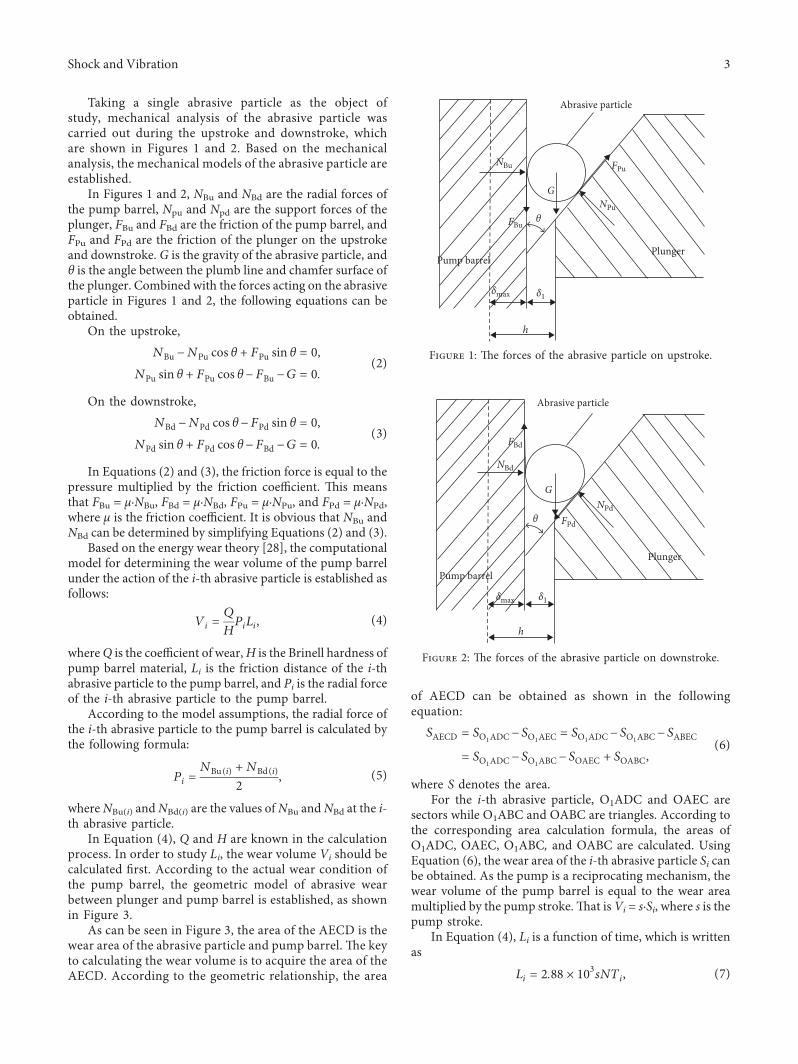
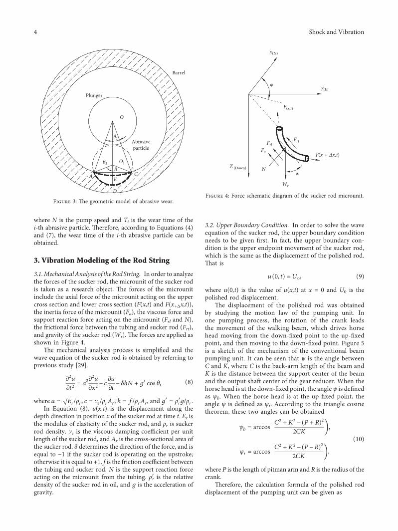
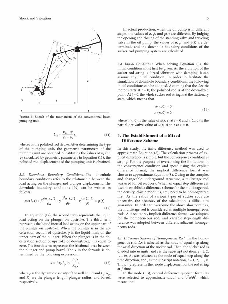
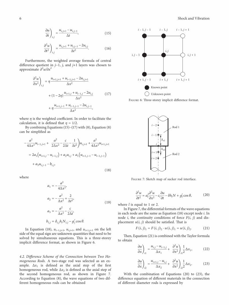
zu
zt1113888 1113889
ij
uij+1 minus uijminus1
Δt (15)
z2u
zt21113888 1113889
ij
uij+1 + uijminus1 minus 2uij
Δt2 (16)
Furthermore the weighted average formula of centraldifference quotient in jminus1 j and j+1 layers was chosen toapproximate z2uzx2
z2u
zx21113888 1113889ij
ηui+1j+1 + uiminus1j+1 minus 2uij+1
Δx2
+(1minus 2η)ui+1j + uiminus1j minus 2uij
Δx2
+ ηui+1jminus1 + uiminus1jminus1 minus 2uijminus1
Δx2
(17)
where η is the weighted coefficient In order to facilitate thecalculation it is defined that η 12
By combining Equations (15)ndash(17) with (8) Equation (8)can be simplified as
minusa2
4Δx2uiminus1j+1 +a2
2Δx2 minusc
2Δtminus
1Δt2
1113888 1113889uij+1 +a2
4Δx2ui+1j+1
2a1 ui+1j minus uiminus1j1113872 1113873 + a2uij + a1 ui+1jminus1 minus uiminus1jminus11113872 1113873
+ a3uijminus1 minus bij
(18)
where
a1 minusa2
4Δx2
a2 minusa2
Δx2 +2Δt2
a3 minusa2
Δx2 minusc
2Δt
bij δijhiNij minusgjprime cos θ
(19)
In Equation (18) uiminus1j+1 uij+1 and ui+1j+1 on the leftside of the equal sign are unknown quantities that need to besolved by simultaneous equations is is a three-storeyimplicit difference format as shown in Figure 6
42 Difference Scheme of the Connection between Two Ho-mogeneous Rods A two-stage rod was selected as an ex-ample Δx1 is defined as the axial step of the firsthomogeneous rod while Δx2 is defined as the axial step ofthe second homogeneous rod as shown in Figure 7According to Equation (8) the wave equations of two dif-ferent homogeneous rods can be obtained
z2u
zt2 a
2l
z2u
zx2 minus cl
zu
ztminus δhlN + gl
prime cos θ (20)
where l is equal to 1 or 2In Figure 7 the differential formats of the wave equations
in each node are the same as Equation (18) except node i Innode i the continuity conditions of force F(i j) and dis-placement u(i j) should be satisfied at is
F(i j)1 F(i j)2 middot u(i j)1 u(i j)2 (21)
en Equation (21) is combined with the Taylor formulato obtain
zu
zx1113888 1113889
i1
uij minus uiminus1j
Δx1+
z2u
zx21113888 1113889i1
12Δx1 (22)
zu
zx1113888 1113889
i2
ui+1j minus uij
Δx2+
z2u
zx21113888 1113889i2
12Δx2 (23)
With the combination of Equations (20) to (23) thedifference equation of different materials in the connectionof different diameter rods is expressed by
Known point
Unknown point
i + 1 j
i ndash 1 j
i + 1 j + 1i + 1 j ndash 1
i ndash 1 j ndash 1 i ndash 1 j + 1
i j + 1i j ndash 1i j
Figure 6 ree-storey implicit difference format
i ndash 2
i ndash 1
i + 1
i + 2
i∆x1
∆x2
Rod 1
Rod 2
Figure 7 Sketch map of sucker rod interface
6 Shock and Vibration
uij+1 2b1 + b2 minus v2 minus v1( 1113857minus b1uij + v2ui+1j + v1uiminus1j
b1 + b2
minusr1 δijh1iNij minusg1j
prime cos θi1113872 1113873 + r2 δijh2iNij minusg1jprime cos θi1113872 1113873
b1 + b2
(24)
where
b1 ΔxErAr( 11138571
2 a1Δt( 11138572 +ΔxErAr( 11138572
2 a2Δt( 11138572
b2 ΔxErArc( 111385712a2
1Δt+ΔxErArc( 111385722a2
2Δt
ri ΔxErAr( 1113857i
2a21
vi ErAr( 1113857i
Δxi
i 1 2
(25)
5 Instance Calculation and Analysis
In order to investigate the true wear condition between theplunger and pump barrel an example is given e sim-ulation parameters are listed in Table 1 By substituting theparameters in Table 1 in Equation (6) the wear area ofa single abrasive is calculated and then the wear volume ofa single abrasive can be obtained as shown in Figure 8
Figure 8 shows the variation of wear volume withabrasive diameter In Figure 8 the wear volume of eachabrasive increases with the increase in abrasive diameterFurther observation of the wear volume curve in Figure 8shows that the slope of the wear volume curve increases withthe increase in abrasive diameter is indicates that thewear volume rate increases with the abrasive diameter
Taking the calculated wear volume into Equation (4) theabrasive wear distance Li can be obtained Using Equation(7) the wear time of a single abrasive particle is achieved asshown in Figure 9
Figure 9 describes the change curves of wear time withparticle diameter under different θ where θ is the anglebetween the plumb line and chamfer surface of the plungerFrom Figure 9 it is found that the wear times of threedifferent θ always increase with the increase in abrasivediameter Further observation of Figure 9 shows that theslope of the wear time curve decreases with the increase inabrasive diameter which indicates that the rate of increase ofwear time decreases with the increase in abrasive diameterComparison of the three curves shows that the increase of θextends the wear time of each abrasive
With the increase in wear time the increase in weardepth affects the change of clearance of the plunger andpump barrel To further discuss the influence of wear onthe sucker rod pumping system the clearance of theplunger and pump barrel was selected as a parameterie δ Well L2111 in the Liao He Oilfield was selected for
the experiments Tables 2 and 3 list the relevant param-eters of the pumping unit sucker rod oil pump andtubing respectively In Table 2 A represents beam frontarm length C represents beam rear arm length P rep-resents the length of pitman arm G represents the heightfrom the center of the speed reducer output shaft Hrepresents the height from beam support center to thebottom of the pedestal I represents the horizontal dis-tance between beam support center and the center of thespeed reducer output shaft and R represents the radius ofthe crank
According to the parameter data of the pump unit inTable 2 the polished rod displacement curve can be achievedby solving Equation (11) as shown in Figure 10 By de-termining the surface boundary conditions of the polishedrod displacement the wave equation can be solved and thepolished rod load of sucker rod pumping system can beobtained
Figure 11 describes the variation trend of polished rodload with δ in well L2111 where δ is the clearance of theplunger and pump barrel To better illustrate the effect ofwear on the system three different values of δ were con-sidered It can be seen that δ influences the polished rodload Comparison of the three curves in Figure 11 showsthat there is an obvious decrease in polished rod load withthe increase of δ on the upstroke is is because withincreasing pumping time the wear depth between theplunger and pump barrel increases e increase of δ willlead to an increase in leakage between the plunger andpump barrel which will reduce lifting oil production andpolished rod load At the same time with the increase of δthe influence of δ on load gradually decreases On thedownstroke the influence of δ changes on the polished rodload is very small is is because the traveling valve isopen and oil is flowing in the pump No liquid columnloading was found on the plunger In the whole pumpingprocess the changes in δ caused by wear between theplunger and pump barrel will affect the change in polishedrod dynamometer cards of the sucker rod pumping systemwhich cannot be ignored
6 Conclusion
(1) In order to study the influence of wear between theplunger and pump barrel of the oil pump on thepolished rod dynamometer card the wear model ofthe plunger-pump barrel was established On thebasis of considering abrasive wear the forces on theabrasive particle were analyzed By calculating thewear area of abrasive particles the change curves ofwear volume and wear time versus abrasive particlediameter were obtained
(2) e wave equation of the sucker rod string froma previous study was selected and the upperboundary condition downhole boundary conditionand initial condition were determined A three-storey implicit difference format was applied tothe homogeneous rod while the variable step-length
Shock and Vibration 7
difference format was adopted between adjacentdifferent homogeneous rods Finally the waveequation was solved by the mixed finite differencemethod
(3) In order to discuss the influence of wear on thepolished rod dynamometer card a well from theLiao He Oilfield was used for the experiment e
polished rod dynamometer card shows that the in-crease in clearance between the plunger and pumpbarrel leads to a decrease in polished rod load onupstroke In view of the influence of clearance on thepolished rod dynamometer card it is meaningful tostudy the sucker rod pumping system by consideringthe wear between the plunger and pump barrel
Table 1 Simulation parameters of wear
e parameter name Values e parameter name Values e parameter name ValuesPump stroke 354 (m) Pump speed 245 (minminus1) Pump diameter 44 (mm)Wear coefficient 65 Dynamic friction coefficient 0145 Abrasive density 2560 (kgm3)Pump barrel hardness 280 (Nmm2) Initial clearance 005 (mm) Clearance increment 00005 (mm)
5 55 6 65 7 75 8 85 9 95 10
times10ndash5
0
1
2
3
4
5
6
7
8times10ndash9
Abrasive diameter (m)
Wea
r vol
ume (
m3 )
Figure 8 Wear volume change curve
5 55 6 65 7 75 8 85 9 95 10
times10ndash5
0
5
10
15
20
25
Abrasive diameter (m)
Wea
r tim
e (da
y)
θ = 5degθ = 6degθ = 7deg
Figure 9 Wear time change curves
8 Shock and Vibration
Table 2 Equipment parameters of pump unit pump and tubing
e parameter name Values e parameter name Values e parameter name ValuesPump stroke 354 (m) Pump speed 245 (minminus1) A 481 (m)C 2906 (m) P 4 (m) G 2 (m)H 6 (m) I 7 (m) R 104 (m)Pump diameter ϕ44 (mm) Pump depth 1997 (m) Plunger area 1134times10minus4 (m2)Cross-sectional area of tubing 56times10minus4 (m2) Flow area of tubing 128times10minus4 (m2) Elastic constant of tubing 867times10minus6 (kN)minus1
Table 3 Equipment parameters of sucker rod
Sucker rod diameter Length Cross-sectional area Deadweight Elastic constantϕ19mm 710m 284times10minus4m2 235times10minus2 kNm 1664times10minus5 (kN)minus1
ϕ22mm 890m 380times10minus4m2 314times10minus2 kNm 1241times 10minus5 (kN)minus1
ϕ25mm 174m 491times 10minus4m2 409times10minus2 kNm 0961times 10minus5 (kN)minus1
0 50 100 150 200 250 300 350 4000
05
1
15
2
25
3
35
4
Crank angle (deg)
Polis
hed
rod
disp
lace
men
t (m
)
Figure 10 e displacement curve of polished rod
0 05 1 15 2 25 3 35 440
45
50
55
60
65
70
Stoke (m)
Load
(kN
)
δ = 00500mmδ = 00515mmδ = 00530mm
Figure 11 Polished rod dynamometer cards of well L2111
Shock and Vibration 9
Data Availability
e parameters required in the simulation and experimentare given in Tables 1 2 and 3 in the article or can be obtainedfrom the corresponding author upon request
Conflicts of Interest
e authors declare that they have no conflicts of interest
Acknowledgments
e financial supports of National Natural Science Foun-dation of China (51275404) and Shaanxi 13115 Major RampDProject (2009ZDKG-33) and data support of Liao HeOilfield are gratefully acknowledged
References
[1] W Du ldquoObservations of Chinarsquos oil industry in the 13th five-year plan periodrdquo International Petroleum Economics vol 25no 4 pp 28ndash32 2017 in Chinese
[2] K Li Y Han and T Wang ldquoA novel prediction method fordown-hole working conditions of the beam pumping unitbased on 8-directions chain codes and online sequentialextreme learning machinerdquo Journal of Petroleum Science andEngineering vol 160 pp 285ndash301 2018
[3] H J Meng L Quan Z L Wang C W Wang and Y LanldquoAn energy-saving pumping system with novel springs energystorage devices design modeling and experimentrdquo Advancesin Mechanical Engineering vol 9 no 1 pp 1ndash11 2017
[4] K Li and Y Han ldquoModelling for motor load torque withdynamic load changes of beam pumping units based ona serial hybrid modelrdquo Transactions of the Institute of Mea-surement and Control vol 40 no 3 pp 903ndash917 2018
[5] K Wang ldquoModeling method for fault diagnosis to sucker rodpumping system in directional wellrdquo Journal of China Uni-versity of Petroleum vol 34 no 2 pp 130ndash135 2010 inChinese
[6] MM Xing S M Dong Z X Tong R F Ran and H L ChenldquoDynamic simulation and efficiency analysis of beampumping systemrdquo Journal of Central South University vol 22no 9 pp 3367ndash3379 2015
[7] K Li X W Gao H B Zhou and Y Han ldquoFault diagnosis fordown-hole conditions of sucker rod pumping systems basedon the FBH-SC methodrdquo Petroleum Science vol 12 no 1pp 135ndash147 2015
[8] L M Lao and H Zhou ldquoApplication and effect of buoyancyon sucker rod string dynamicsrdquo Journal of Petroleum Scienceamp Engineering vol 146 pp 264ndash271 2016
[9] T Ren X Q Kang W Sun and H Song ldquoStudy of dyna-mometer cards identification based on root-mean-squareerror algorithmrdquo International Journal of Pattern Recogni-tion amp Artificial Intelligence vol 32 no 2 article 18500042017
[10] B Y Zheng and X W Gao ldquoSucker rod pumping diagnosisusing valve working position and parameter optimal con-tinuous hidden Markov modelrdquo Journal of Process Controlvol 59 pp 1ndash12 2017
[11] A Zhang and X W Gao ldquoFault diagnosis of sucker rodpumping systems based on Curvelet Transform and sparsemulti-graph regularized extreme learning machinerdquo In-ternational Journal of Computational Intelligence Systemsvol 11 no 1 pp 428ndash437 2018
[12] X M Wu and X R Wang ldquoMathematical simulation ofcalculation chart for oil pumping rod loadrdquo in Proceedings ofAsia-Pacific Conference on Information Processing vol 2pp 407ndash409 IEEE Computer Society Shenzhen China 2009
[13] S G Gibbs ldquoPredicting the behavior of sucker-rod pumpingsystemsrdquo Journal of Petroleum Technology vol 15 no 7pp 769ndash778 1963
[14] S G Gibbs ldquoA review of methods for design and analysis ofrod pumping installationsrdquo Journal of Petroleum Technologyvol 34 no 12 pp 2931ndash2940 1982
[15] D R Doty and Z Schmidt ldquoAn improved model for suckerrod pumpingrdquo Society of Petroleum Engineers Journal vol 23no 1 pp 33ndash41 1983
[16] G W Wang S S Rahman and G Y Yang ldquoAn improvedmodel for the sucker rod pumping systemrdquo in Proceedings of11th Australasian Fluid Mechanics Conference pp 1137ndash1140Australasian Fluid Mechanics Society Hobart Australia1992
[17] G H Luan S L He and Z Yang ldquoA prediction model fora new deep-rod pumping systemrdquo Journal of PetroleumScience and Engineering vol 80 no 1 pp 75ndash80 2012
[18] G Takacs ldquoExact kinematic and torsional analysis of rotaflexpumping unitsrdquo Journal of Petroleum Science and Engineer-ing vol 115 no 3 pp 11ndash16 2014
[19] Y Q Yu Z Y Chang Y G Qi X Xue and J N Zhao ldquoStudyof a new hydraulic pumping unit based on the offshoreplatformrdquo Energy Science amp Engineering vol 4 no 5pp 352ndash360 2016
[20] X F Liu and Y G Qi ldquoA modern approach to the selection ofsucker rod pumping systems in CBM wellsrdquo Journal of Pe-troleum Science and Engineering vol 76 no 3 pp 100ndash1082011
[21] X F Liu ldquoPrediction of flowing bottomhole pressures fortwo-phase coalbed methane wellsrdquo Acta Geologica Sinica-English Edition vol 87 no 5 pp 1412ndash1420 2013
[22] X F Liu C H Liu and Y Yang ldquoDynamic behavior of thepolished rod for the coalbed methane pumping installationsrdquoOil amp Gas Science and Technology vol 72 no 3 p 16 2017
[23] R B Gong W R Zhu and J Y Ding ldquoTrend Prediction ofindicator diagram based on least squares support vectormachinesrdquo Petroleum Planning amp Engineering vol 26 no 4pp 24ndash27 2015 in Chinese
[24] X Y Li X W Gao Y B Hou and H R Wang ldquoCoupleddynamic modeling for polished rod load of beam pumpingunitrdquo Journal of Northeastern University (Natural Science)vol 37 no 9 pp 1225ndash1229 2016 in Chinese
[25] Z M Feng J J Tan X L Liu and F Xin ldquoSelection methodmodelling and matching rule for rated power of prime motorused by beam pumping unitsrdquo Journal of Petroleum Scienceand Engineering vol 153 pp 197ndash202 2017
[26] Z S Chen L W White and H M Zhang ldquoPredicting be-havior of sucker-rod pumping systems with optimal controlrdquoJournal of Dynamic Systems Measurement and Controlvol 140 no 5 article 051004 2017
[27] F J Bu ldquoAnalysis and solution of the wear mechanism of thepumprdquo Journal of Shengli Oilfield Staff University vol 1pp 70ndash72 2007 in Chinese
[28] T Dyck and A Bund ldquoAn adaption of the Archard equationfor electrical contacts with thin coatingsrdquo Tribology In-ternational vol 102 pp 1ndash9 2016
[29] S M Dong and B S Li Design of Sucker Rod Pumping Systemin Horizontal Wells Petroleum Industry Press Beijing China1996 in Chinese
10 Shock and Vibration
International Journal of
AerospaceEngineeringHindawiwwwhindawicom Volume 2018
RoboticsJournal of
Hindawiwwwhindawicom Volume 2018
Hindawiwwwhindawicom Volume 2018
Active and Passive Electronic Components
VLSI Design
Hindawiwwwhindawicom Volume 2018
Hindawiwwwhindawicom Volume 2018
Shock and Vibration
Hindawiwwwhindawicom Volume 2018
Civil EngineeringAdvances in
Acoustics and VibrationAdvances in
Hindawiwwwhindawicom Volume 2018
Hindawiwwwhindawicom Volume 2018
Electrical and Computer Engineering
Journal of
Advances inOptoElectronics
Hindawiwwwhindawicom
Volume 2018
Hindawi Publishing Corporation httpwwwhindawicom Volume 2013Hindawiwwwhindawicom
The Scientific World Journal
Volume 2018
Control Scienceand Engineering
Journal of
Hindawiwwwhindawicom Volume 2018
Hindawiwwwhindawicom
Journal ofEngineeringVolume 2018
SensorsJournal of
Hindawiwwwhindawicom Volume 2018
International Journal of
RotatingMachinery
Hindawiwwwhindawicom Volume 2018
Modelling ampSimulationin EngineeringHindawiwwwhindawicom Volume 2018
Hindawiwwwhindawicom Volume 2018
Chemical EngineeringInternational Journal of Antennas and
Propagation
International Journal of
Hindawiwwwhindawicom Volume 2018
Hindawiwwwhindawicom Volume 2018
Navigation and Observation
International Journal of
Hindawi
wwwhindawicom Volume 2018
Advances in
Multimedia
Submit your manuscripts atwwwhindawicom
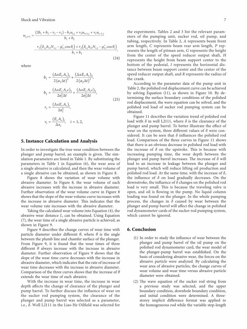
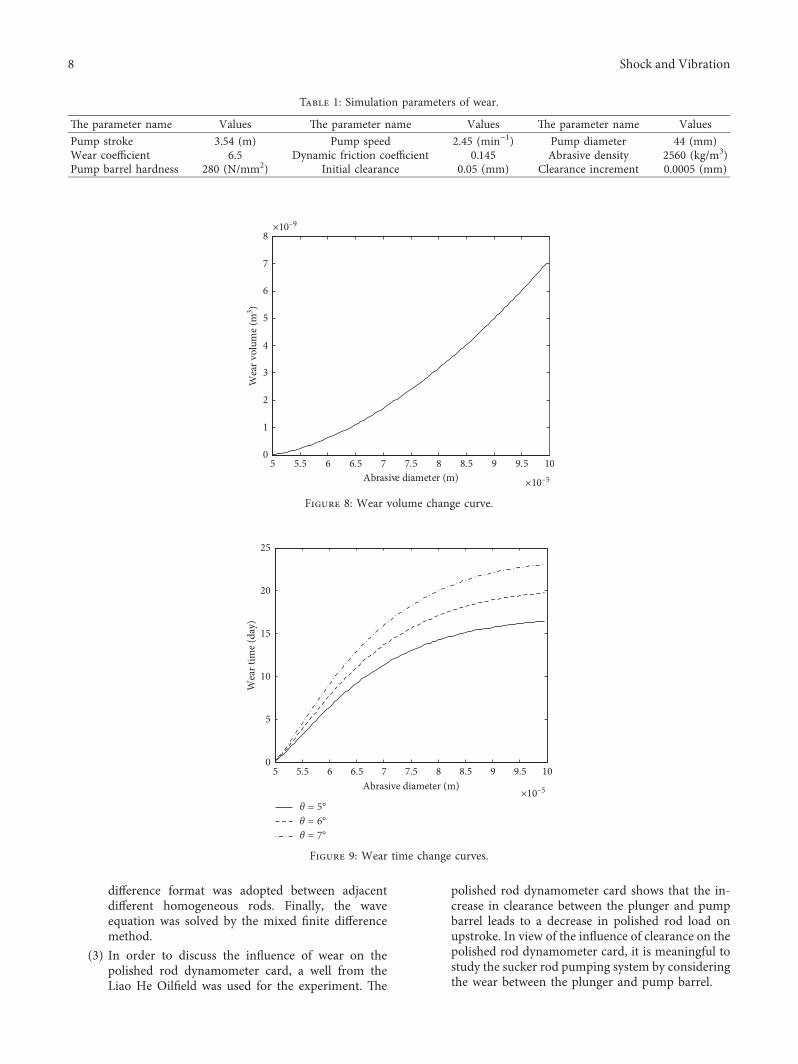
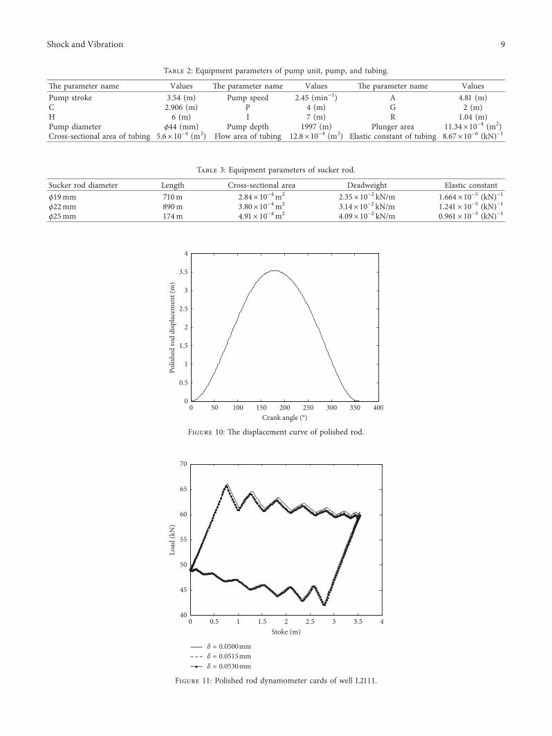
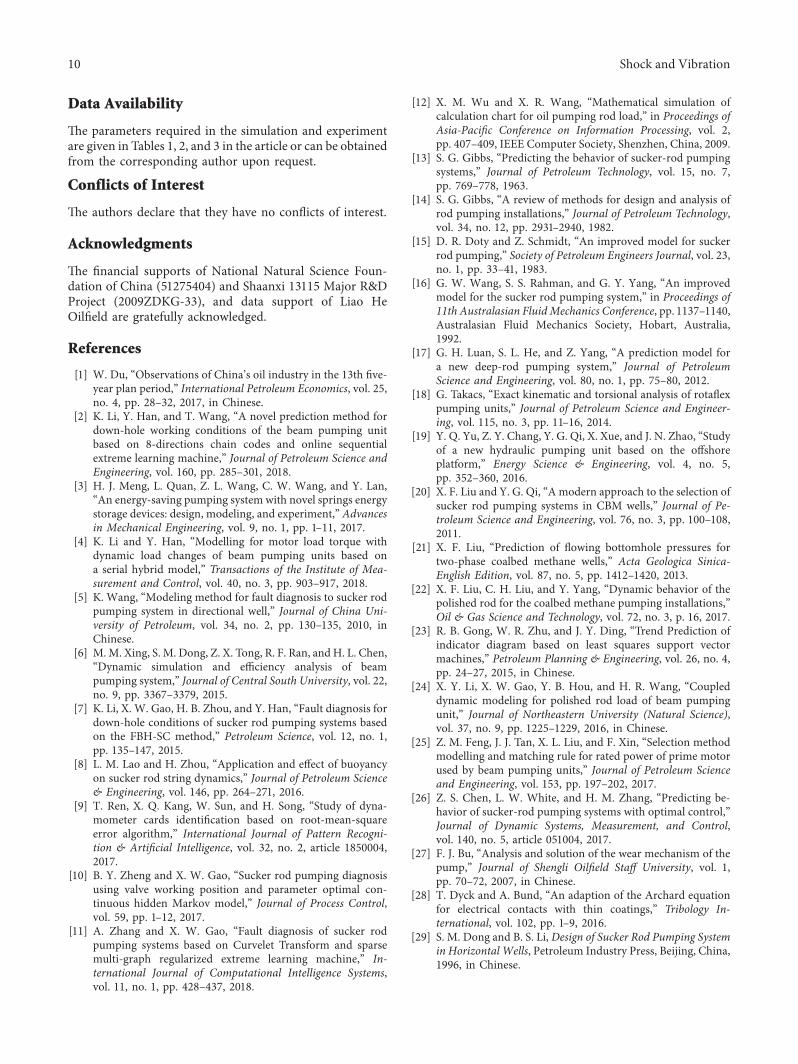

International Journal of
AerospaceEngineeringHindawiwwwhindawicom Volume 2018
RoboticsJournal of
Hindawiwwwhindawicom Volume 2018
Hindawiwwwhindawicom Volume 2018
Active and Passive Electronic Components
VLSI Design
Hindawiwwwhindawicom Volume 2018
Hindawiwwwhindawicom Volume 2018
Shock and Vibration
Hindawiwwwhindawicom Volume 2018
Civil EngineeringAdvances in
Acoustics and VibrationAdvances in
Hindawiwwwhindawicom Volume 2018
Hindawiwwwhindawicom Volume 2018
Electrical and Computer Engineering
Journal of
Advances inOptoElectronics
Hindawiwwwhindawicom
Volume 2018
Hindawi Publishing Corporation httpwwwhindawicom Volume 2013Hindawiwwwhindawicom
The Scientific World Journal
Volume 2018
Control Scienceand Engineering
Journal of
Hindawiwwwhindawicom Volume 2018
Hindawiwwwhindawicom
Journal ofEngineeringVolume 2018
SensorsJournal of
Hindawiwwwhindawicom Volume 2018
International Journal of
RotatingMachinery
Hindawiwwwhindawicom Volume 2018
Modelling ampSimulationin EngineeringHindawiwwwhindawicom Volume 2018
Hindawiwwwhindawicom Volume 2018
Chemical EngineeringInternational Journal of Antennas and
Propagation
International Journal of
Hindawiwwwhindawicom Volume 2018
Hindawiwwwhindawicom Volume 2018
Navigation and Observation
International Journal of
Hindawi
wwwhindawicom Volume 2018
Advances in
Multimedia
Submit your manuscripts atwwwhindawicom