
Precursors and Manufacturing of Carbon Fibers - Springer
37
Chapter 2 Precursors and Manufacturing of Carbon Fibers Soo-Jin Park and Gun-Young Heo Abstract In this chapter, we will present the precursors and manufacturing of carbon fibers. Among the precursors used for the production of carbon fibers, polyacrylonitrile (PAN)-based and pitch-based precursors are the most important. A significant amount of work has been done on relating the fiber structure to the properties and translating that relationship into production for either reducing cost or increasing fiber properties. However, challenges, including cost reduction, improvement in tensile and compressive strength, and alternative precursor development, still remain. We will also introduce many linear and cyclic polymers for carbon fibers, which is expected to open the door for the low-cost carbon fibers. 2.1 Introduction Carbon fibers are novel high-performance materials. They could be described as fibers containing at least 90 % carbon obtained by the controlled pyrolysis of appropriate fibers. Edison in 1879 found that carbon fibers can be used as carbon filaments in electric lamps. Since the early work of Edison, the carbon fibers have been investi- gated and used intensively because they generally have excellent tensile properties, low densities, high thermal and chemical stabilities in the absence of oxidizing agents, good thermal and electrical conductivities, and excellent creep resistance [1–16]. In recent years, the carbon fiber industry has been growing steadily to meet the demands arising from different applications such as aerospace (aircraft and space systems), military, turbine blades, construction, lightweight cylinders and pressure vessels, medical, automobile, and sporting goods. Furthermore, in the case of the carbon fibers, the range of their applications would depend on the type of precursors used to produce the carbon fibers. Consequently, many types of precursors have been studied to produce the carbon fibers. The ideal features of precursors required S.-J. Park (&) G.-Y. Heo Department of Chemistry, Inha University, 100 Inharo, Incheon, Republic of Korea e-mail: [email protected] © Springer Science+Business Media Dordrecht 2015 S.-J. Park, Carbon Fibers, Springer Series in Materials Science 210, DOI 10.1007/978-94-017-9478-7_2 31
Transcript of Precursors and Manufacturing of Carbon Fibers - Springer

Chapter 2Precursors and Manufacturing of CarbonFibers
Soo-Jin Park and Gun-Young Heo
Abstract In this chapter, we will present the precursors and manufacturing ofcarbon fibers. Among the precursors used for the production of carbon fibers,polyacrylonitrile (PAN)-based and pitch-based precursors are the most important. Asignificant amount of work has been done on relating the fiber structure to theproperties and translating that relationship into production for either reducing costor increasing fiber properties. However, challenges, including cost reduction,improvement in tensile and compressive strength, and alternative precursordevelopment, still remain. We will also introduce many linear and cyclic polymersfor carbon fibers, which is expected to open the door for the low-cost carbon fibers.
2.1 Introduction
Carbonfibers are novel high-performancematerials. They could be described asfiberscontaining at least 90 % carbon obtained by the controlled pyrolysis of appropriatefibers. Edison in 1879 found that carbon fibers can be used as carbon filaments inelectric lamps. Since the early work of Edison, the carbon fibers have been investi-gated and used intensively because they generally have excellent tensile properties,low densities, high thermal and chemical stabilities in the absence of oxidizing agents,good thermal and electrical conductivities, and excellent creep resistance [1–16].
In recent years, the carbon fiber industry has been growing steadily to meet thedemands arising from different applications such as aerospace (aircraft and spacesystems), military, turbine blades, construction, lightweight cylinders and pressurevessels, medical, automobile, and sporting goods. Furthermore, in the case of thecarbon fibers, the range of their applications would depend on the type of precursorsused to produce the carbon fibers. Consequently, many types of precursors havebeen studied to produce the carbon fibers. The ideal features of precursors required
S.-J. Park (&) � G.-Y. HeoDepartment of Chemistry, Inha University, 100 Inharo, Incheon, Republic of Koreae-mail: [email protected]
© Springer Science+Business Media Dordrecht 2015S.-J. Park, Carbon Fibers, Springer Series in Materials Science 210,DOI 10.1007/978-94-017-9478-7_2
31
to manufacture carbon fibers are easy conversion to carbon fiber, high carbon yield,and cost-effective processing. From this perspective, the following four types ofprecursors have been widely used, which have also proven to be the most popularones [17–31]:
1. Acrylic precursors: They have been successfully used for carbon fiber prepa-ration by most industrial manufacturers for quite some time now. These acrylicprecursors contain >85 % acrylonitrile (AN) monomer. In particular, polyac-rylonitrile (PAN) is the most popular acrylic precursor, which is used widely toproduce the carbon fibers.
2. Cellulosic precursors: They contain 44.4 % carbon. However, in practice, thereaction is more complicated than mere dehydration, and the carbon yield isonly approximately 25–30 %.
3. Pitch-based precursors: They have a yield of 85 %, and the resultant carbonfibers from these precursors show a high modulus owing to the more graphiticnature. On the other hand, the pitch-based carbon fibers have poorer compres-sion and transverse properties compared to the PAN-based carbon fibers.
4. Other forms of precursors: Vinylidene chloride and phenolic resins as precursorsfor the manufacture of carbon fibers have been investigated, but were not foundto be commercially viable.
2.2 Acrylic Precursors
Various acrylic precursors have been utilized to produce carbon fibers for use incarbon-fiber-based composite applications owing to certain desirable physicalproperties [32, 33]. The acrylic precursors for the carbon fiber industry originatedfrom the companies that were established commercial-scale producers of textile-grade acrylic fibers. This was because the carbon fibers were produced through thepyrolysis of the acrylic fibers. Therefore, the manufacturers of carbon fibers couldmost readily adapt the existing technology for precursors to manufacture carbonfibers. The manufacturing processes of acrylic precursors by various manufacturersare listed in Table 2.1. In particular, the resultant carbon fibers from acrylic pre-cursors such as PAN-based carbon fibers have been widely used as reinforcingmaterials in automobile, aerospace, recreational, and various other industries[34–37].
2.2.1 PAN Precursors
PAN-based polymer precursors for carbon fibers could be primarily classified intopure homopolymer and comonomers. Generally, the comonomers are widely usedin PAN-based polymer precursors to manufacture carbon fibers [38–40].
32 2 Precursors and Manufacturing of Carbon Fibers

The homopolymer PAN product is slightly difficult to process into carbon fibersbecause the initial oxidation stage of the process cannot be easily controlled owingto the sudden and rapid evolution of heat, coupled with a relatively high initiationtemperature. Such heat could result in poor properties of carbon fibers owing to thechain scission from the thermal shock. It is known that the homopolymer PANproduct has never been used as a precursor for manufacturing carbon fibers. Toovercome the resultant poor properties in the carbon fibers due to the rapid evo-lution of heat, the exothermic reaction should be adequately controlled usingsuitable comonomers such as itaconic acid.
On the other hand, as mentioned above, the comonomers could exert a signifi-cant effect on the stabilization process, thereby enhancing the segmental mobility ofthe polymer chains resulting in better orientation and mechanical properties of theprecursor and manufactured carbon fibers. In addition, the selection of suitablecomonomers could reduce the initial temperature of cyclization in the manufac-turing process of carbon fibers. Therefore, several researchers have discussed theeffect of comonomer composition on the properties of the PAN precursor andresultant carbon fibers.
Vinyl esters such as vinyl acetate (VAc), methacrylate (MA), and methylmethacrylate (MMA) could be used as comonomers for AN, though VAc might notbe an appropriate carbon fiber precursor [41–44]. These comonomers act like aplasticizer and break up the structure to make the polymer more readily soluble in thespinning solvent, thereby improving the quality of spinning, modifying the fibermorphology and where appropriate, and improving the rate of diffusion of the dyeinto the fibers. However, the comonomers should be minimally used for establishinggood properties in the carbon fibers because they could affect the cyclization step inthe manufacturing process of carbon fibers. Table 2.2 lists the possible comonomers.These monomers have similar reactivities, and the resulting polymer compositionswill have more or less the same composition as the monomers in the feed.
Carboxylic acids could be used as effective comonomers because their presenceaffects the ease of oxidation, exothermicity, and carbon yield of the precursor. Inaddition, itaconic and methacrylic acids have been confirmed to be most effective
Table 2.1 Manufacturing processes for acrylic precursors
Manufacturers Tradename
Type of polymerization Solvent Typical % ofpolymer
Accordis Courtelle Continuous solution NaCNS 10–15
Asahi Cashmilon Continuous aqueousdispersion
H2O/HNO3 8–12
Hexcel Exlan Continuous aqueousdispersion
H2O/NaCNS
10–15
Mitsubishi Finel Continuous aqueousdispersion
H2O/DMAC
22–27
Toho Beslon Continuous solution ZnCl2 8–12
Toray Toraylon Batch solution DMSO 20–25
2.2 Acrylic Precursors 33
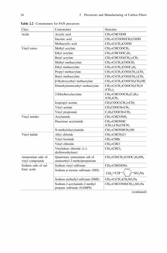
Table 2.2 Comonomers for PAN precursors
Class Comonomer Structure
Acids Acrylic acid CH2=CHCOOH
Itaconic acid CH2=C(COOH)CH2COOH
Methacrylic acid CH2=C(CH3)COOH
Vinyl esters Methyl acrylate CH2=CHCOOCH3
Ethyl acrylate CH2=CHCOOC2H5
Butyl acrylate CH2=CHCOO(CH2)3CH3
Methyl methacrylate CH2=C(CH3)COOCH3
Ethyl methacrylate CH2=C(CH3)COOC2H5
Propyl methacrylate CH2=C(CH3)COO(CH2)2CH3
Butyl methacrylate CH2=C(CH3)COO(CH2)3CH3
β-Hydroxyethyl methacrylate CH2=C(CH3)COOCH2CH2OH
Dimethylaminoethyl methacrylate CH2=C(CH3)COOCH2CH2N(CH3)2
2-Ethylhexylacrylate CH2=CHCOOCH2(C2H5)(CH2)CH3
Isopropyl acetate CH3COOC(CH3)=CH2
Vinyl acetate CH3COOCH=CH2
Vinyl propionate C2H5COOCH=CH2
Vinyl amides Acrylamide CH2=CHCONH2
Diacetone acrylamide CH2=CHONHC(CH3)2CH2COCH3
N-methylolacrylamide CH2=CHONHCH2OH
Vinyl halide Allyl chloride CH2=CHCH2Cl
Vinyl bromide CH2=CHBr
Vinyl chloride CH2=CHCl
Vinylidene chloride (1,1-dichloroethylene)
CH2=CHCl2
Ammonium salts ofvinyl compounds
Quaternary ammonium salt ofaminoethyl-2-methylpropenoate
CH2=CH(CH3)COOC2H4NH2
Sodium salts of sul-fonic acids
Sodium vinyl sulfonate CH2=CHSOONa
Sodium p-styrene sulfonate (SSS)CH SO3NaCH2
Sodium methallyl sulfonate (SMS) CH2=C(CH3)CH2SO3Na
Sodium-2-acrylamido-2-methylpropane sulfonate (SAMPS)
CH2=CHCONH(CH2)3SO3Na
(continued)
34 2 Precursors and Manufacturing of Carbon Fibers
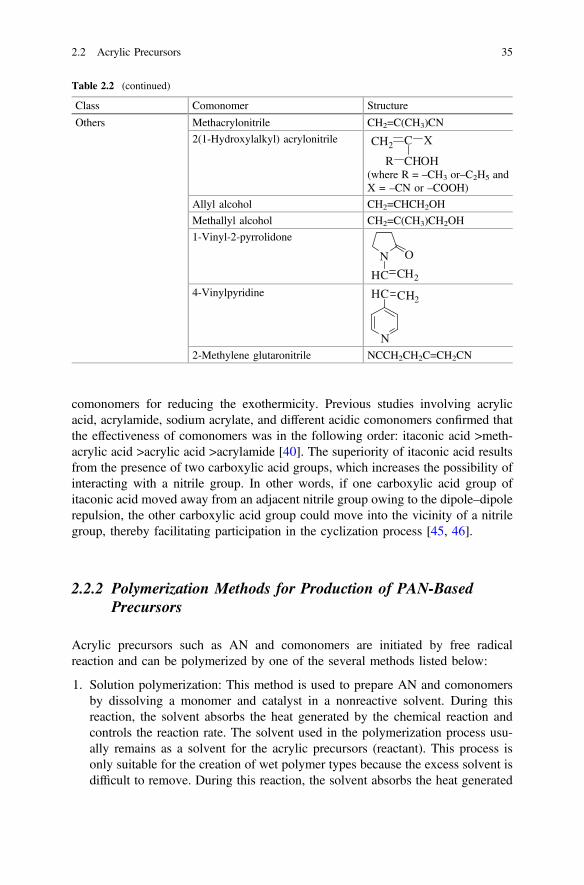
comonomers for reducing the exothermicity. Previous studies involving acrylicacid, acrylamide, sodium acrylate, and different acidic comonomers confirmed thatthe effectiveness of comonomers was in the following order: itaconic acid >meth-acrylic acid >acrylic acid >acrylamide [40]. The superiority of itaconic acid resultsfrom the presence of two carboxylic acid groups, which increases the possibility ofinteracting with a nitrile group. In other words, if one carboxylic acid group ofitaconic acid moved away from an adjacent nitrile group owing to the dipole–dipolerepulsion, the other carboxylic acid group could move into the vicinity of a nitrilegroup, thereby facilitating participation in the cyclization process [45, 46].
2.2.2 Polymerization Methods for Production of PAN-BasedPrecursors
Acrylic precursors such as AN and comonomers are initiated by free radicalreaction and can be polymerized by one of the several methods listed below:
1. Solution polymerization: This method is used to prepare AN and comonomersby dissolving a monomer and catalyst in a nonreactive solvent. During thisreaction, the solvent absorbs the heat generated by the chemical reaction andcontrols the reaction rate. The solvent used in the polymerization process usu-ally remains as a solvent for the acrylic precursors (reactant). This process isonly suitable for the creation of wet polymer types because the excess solvent isdifficult to remove. During this reaction, the solvent absorbs the heat generated
Table 2.2 (continued)
Class Comonomer Structure
Others Methacrylonitrile CH2=C(CH3)CN
2(1-Hydroxylalkyl) acrylonitrile C XCH2
CHOHR(where R = –CH3 or–C2H5 andX = –CN or –COOH)
Allyl alcohol CH2=CHCH2OH
Methallyl alcohol CH2=C(CH3)CH2OH
1-Vinyl-2-pyrrolidone
N
HC CH2
O
4-Vinylpyridine
N
HC CH2
2-Methylene glutaronitrile NCCH2CH2C=CH2CN
2.2 Acrylic Precursors 35

by the chemical reaction and controls the reaction rate. The solvent used in thepolymerization process usually remains as a solvent for the acrylic precursors(reactant). This process is only suitable for the creation of wet polymer typesbecause the excess solvent is difficult to remove. Although the removal ofexcess solvent is possible using distillation, this method is usually not com-mercially viable. This polymerization method for the preparation of PAN-basedprecursors offers a few advantages as along with one major disadvantage [47].
2. Bulk polymerization: This method is the simplest and direct way of synthesizingpolymers. This polymerization is carried out by adding a soluble initiator to apure, liquid monomer. The initiator dissolves in the monomer, and the reactionis initiated by either heating or exposure to radiation. The mixture becomesviscous as the reaction proceeds. At that instant, the reaction is exothermic and areactant with a broad molecular weight distribution is produced. Therefore, thispolymerization method for the preparation of PAN-based precursors is used inthe small-scale manufacturing process, wherein it is easy to remove the reactionheat [48].
3. Emulsion polymerization: This method is a type of radical polymerization,which is usually carried out with an emulsion containing water, monomer, andsurfactant. The PAN-based precursors are often made commercially usingemulsion polymerization [49].
4. Aqueous dispersion polymerization: This method is useful to prepare micro- orsubmicron-scale monodisperse polymer particles in a single step. In this poly-merization method, all reaction materials are dissolved in the reaction mediumin the initial stage of the polymerization. Then, insoluble spherical polymerparticles, stabilized using steric molecules, are formed and dispersed in thereaction medium. PAN-based precursors could be prepared using this poly-merization method with an ionic monomer to attain a narrow particle size dis-tribution with a mean diameter as low as approximately 3 ± 1.5 μm [50].
2.2.3 Manufacture of Carbon Fibers from PAN-BasedPrecursors
As mentioned earlier, the PAN-based polymers are the optimum precursors for thecarbon fibers owing to a combination of tensile and compressive properties as wellas the carbon yield. The PAN-based fibers were first developed by Dupont in the1940s for use in the textile fiber. The thermal stability of PAN-based fibers was animportant factor in expanding the application of fibers. Later, this property led tofurther research on the heat treatment of PAN fibers. In the early 1960s, PAN fiberswere first carbonized and graphitized by Shindo at the Government IndustrialResearch Institute, Osaka, Japan, and these, in the early 1960s, PAN fibers werefirst carbonized and graph 112 GPa, respectively [51]. The process involvedemploying tension in both stabilization and carbonization steps. According to
36 2 Precursors and Manufacturing of Carbon Fibers

Toray, Shindo’s patent was licensed to Toray in 1970 by the Japanese Ministry ofInternational Trade and Industry (MITI) to produce PAN-based Torayca carbonfibers. During the 1960s, Watt and Johnson at the Royal Aircraft Establishment,England, and Bacon and Hoses at Union Carbide, the USA, also developed amethod for producing carbon fibers from PAN [52–54].
The manufacturing steps for producing the carbon fibers from PAN could becategorized as follows as shown in Fig. 2.1: polymerization of PAN-based pre-cursors, spinning of fibers, thermal stabilization, carbonization, and graphitization.The manufacturing steps for producing the carbon fibers from PAN-based pre-cursors could be categorized as follows as shown in Fig. 2.1: polymerization ofPAN-based precursors, spinning of fibers, thermal stabilization (oxidation), car-bonization, and graphitization Fig. 2.1. In addition, these PAN-based copolymerscontaining 2–15 % acrylic acid, methacrylic acid, MA, and/or itaconic acid aregenerally used as precursors of carbon fibers produced through carbonizationbecause the use of comonomers affects the molecular alignment and stabilizationconditions. The typical carbon yield from PAN-based precursors is approximately50–60 % [55].
The typical manufacturing steps involved in the production of carbon fibers fromPAN-based precursors are listed below:
1. Polymerization of PAN-based precursors and spinning of fibersThe PAN polymer precursor has been widely used as the basic backbone ofchemical structure for spinning precursor fibers. Figure 2.2 shows the chemicalstructure of PAN. In addition, the commercial PAN-based polymer precursorsused for spinning the precursor fibers usually contain approximately 2–10 % ofa comonomer such as methyl acrylate (MA), MMA, or itacon acids (ITA). Mostcarbon companies manufacture their own precursors by in-house technologies.Consequently, the composition of the PAN polymer precursor is not well knownbecause it can control the properties of the final products.Generally, the PAN polymer precursors contain polar nitrile groups and have ahigh melting point, resulting from strong intermolecular interactions. Therefore,
Fig. 2.1 Schematic for manufacturing process of carbon fibers from PAN-based precursors
2.2 Acrylic Precursors 37

the PAN polymer precursors tend to degrade before the temperature reachestheir melting point. The spinning of PAN fibers in the carbon fiber industry isperformed using traditional manufacturing techniques of acrylic textile fibers.Wet spinning is used in most of the commercial manufacturing processes ofcarbon fibers produced from PAN-based polymer precursors. However, it isgradually being replaced by dry jet wet (air gap) spinning [56]. The meltspinning of PAN-based polymer precursors has been previously practised;however, it has yet to become an acceptable manufacturing process of carbonfibers, commercially [57–59]. Figure 2.3 shows the typical layout of a plant forprocessing PAN-based fibers.
2. Thermal stabilization (oxidation)This process is critical to obtaining high-quality carbon fibers and could take upto several hours, depending on the temperature, precursor diameter, and pre-cursor fiber characteristics [60–70]. Proper conditions such as heating rate, time,
CH2 CH
C N n
Fig. 2.2 Chemical structureof PAN
Fig. 2.3 Typical layoutof a plant for processingPAN-based fibers
38 2 Precursors and Manufacturing of Carbon Fibers
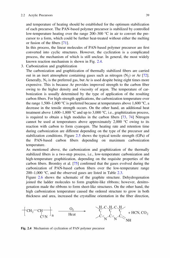
and temperature of heating should be established for the optimum stabilizationof each precursor. The PAN-based polymer precursor is stabilized by controlledlow-temperature heating over the range 200–300 °C in air to convert the pre-cursor to a form, which could be further heat-treated without either the meltingor fusion of the fibers [71].In this process, the linear molecules of PAN-based polymer precursor are firstconverted into cyclic structures. However, the cyclization is a complicatedprocess, the mechanism of which is still unclear. In general, the most widelyknown reaction mechanism is shown in Fig. 2.4.
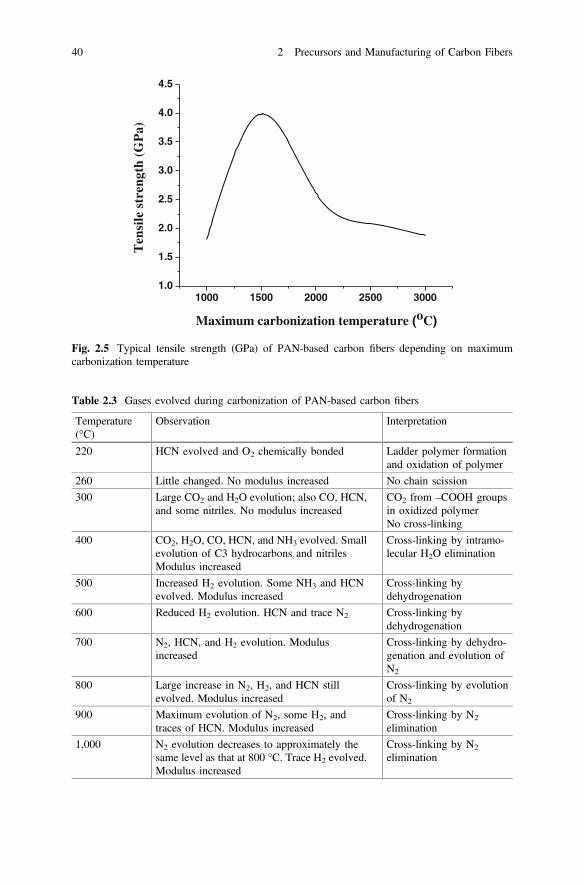
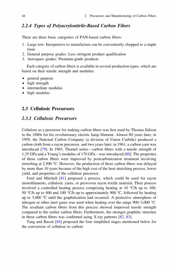
3. Carbonization and graphitizationThe carbonization and graphitization of thermally stabilized fibers are carriedout in an inert atmosphere containing gases such as nitrogen (N2) or Ar [72].Generally, N2 is the preferred gas, but Ar is used despite being eight times moreexpensive. This is because Ar provides improved strength to the carbon fiberowing to the higher density and viscosity of argon. The temperature of car-bonization is usually determined by the type of application of the resultingcarbon fibers. For high-strength applications, the carbonization temperature overthe range 1,500–1,600 °C is preferred because at temperatures above 1,600 °C, adecrease in the tensile strength occurs. On the other hand, an additional heattreatment above 1,600–1,800 °C and up to 3,000 °C, i.e., graphitization process,is required to obtain a high modulus in the carbon fibers [73, 74] Nitrogencannot be used at temperatures above approximately 2,000 °C owing to itsreaction with carbon to form cyanogen. The heating rate and retention timeduring carbonization are different depending on the type of the precursor andstabilization conditions. Figure 2.5 shows the typical tensile strength (GPa) ofthe PAN-based carbon fibers depending on maximum carbonizationtemperature.As mentioned above, the carbonization and graphitization of the thermallystabilized fibers is a two-step process, i.e., low-temperature carbonization andhigh-temperature graphitization, depending on the requisite properties of thecarbon fibers. Bromley et al. [75] confirmed that the gases evolved during thecarbonization of PAN-based carbon fibers over the low-temperature range200–1,000 °C, and the observed gases are listed in Table 2.3.Figure 2.6 shows the schematic of the graphite structure. Dehydrogenationjoined the ladder molecules to form graphite-like ribbons; however, denitro-genation made the ribbons to form sheet-like structures. On the other hand, thehigh carbonization temperature caused the ordered structure to grow in boththickness and area, increased the crystalline orientation in the fiber direction,
CH2 CH
C N n
O2
Heat C
HC
NC
HC
C
NC
HC
C
NH
+ HCN, CO2
Fig. 2.4 Mechanism of cyclization of PAN polymer precursor
2.2 Acrylic Precursors 39
1000 1500 2000 2500 30001.0
1.5
2.0
2.5
3.0
3.5
4.0
4.5
Ten
sile
str
engt
h (G
Pa)
Maximum carbonization temperature (oC)
Fig. 2.5 Typical tensile strength (GPa) of PAN-based carbon fibers depending on maximumcarbonization temperature
Table 2.3 Gases evolved during carbonization of PAN-based carbon fibers
Temperature(°C)
Observation Interpretation
220 HCN evolved and O2 chemically bonded Ladder polymer formationand oxidation of polymer
260 Little changed. No modulus increased No chain scission
300 Large CO2 and H2O evolution; also CO, HCN,and some nitriles. No modulus increased
CO2 from –COOH groupsin oxidized polymerNo cross-linking
400 CO2, H2O, CO, HCN, and NH3 evolved. Smallevolution of C3 hydrocarbons and nitrilesModulus increased
Cross-linking by intramo-lecular H2O elimination
500 Increased H2 evolution. Some NH3 and HCNevolved. Modulus increased
Cross-linking bydehydrogenation
600 Reduced H2 evolution. HCN and trace N2 Cross-linking bydehydrogenation
700 N2, HCN, and H2 evolution. Modulusincreased
Cross-linking by dehydro-genation and evolution ofN2
800 Large increase in N2, H2, and HCN stillevolved. Modulus increased
Cross-linking by evolutionof N2
900 Maximum evolution of N2, some H2, andtraces of HCN. Modulus increased
Cross-linking by N2
elimination
1,000 N2 evolution decreases to approximately thesame level as that at 800 °C. Trace H2 evolved.Modulus increased
Cross-linking by N2
elimination
40 2 Precursors and Manufacturing of Carbon Fibers

and reduced the interlayer spacing and void content. In addition, the graphitestructures could further grow at higher temperatures resulting from the elimi-nation of N2.
4. Surface treatment and washingGenerally, the surface treatment of carbon fibers was performed to improve themechanical properties of the composite through alteration of the fiber surface. Inmany companies, the treatment method of the surface of carbon fibers is stillkept confidential. The most often used surface treatment methods for carbonfibers could be categorized as liquid and gaseous oxidation treatments. Theliquid oxidation treatment is well known and could double the composite shearstrengths with slight reductions (4–6 %) in fiber tensile strengths [76].Among the oxidation treatment methods of the liquid type, the anodic oxidationtreatment method has been widely used in the surface treatment of commercialcarbon fibers because it is inexpensive, fast, and efficient. Figure 2.7 shows the
N
N
N
H
H
H N
N
N
H
H
H
400~600oC Dehydrogenation
N
N
N N
N
N N
N
N N
N
N
600~1300oC Denitrogenation
N
N
NN
N
N
Fig. 2.6 Schematic ofgraphite structure
2.2 Acrylic Precursors 41

schematic of the surface treatment and washing baths. In this method, Faraday’sLaw applies and 96,500 C liberates 1 g equivalent of O2. The duration of thesurface treatment is related to the line speed. In addition, the current density as astandard variable is used to control the treatment level per unit length of carbonfiber during the surface treatment, usually expressed as C/m.The electrically conductive carbon fibers form the anode during the electrolysisof an acid or a salt solution such as nitric acid (HNO3), sulfuric acid (H2SO4),ammonium sulfate ((NH4)2SO4), and ammonium bicarbonate (NH4HCO3) [77].One of the electrolytes, ammonium sulfate, is usually used in the commercialsurface treatment processes of carbon fibers. This causes the carbonyl containinggroups such as COOH to form on the smooth fiber surface. The carbonyl groupsimprove the cohesion between the fiber and resin used in the final composite.After this surface treatment, the excess electrolyte is removed using warm waterwash treatment. The carbon fibers are then passed onto the next process throughone or more water baths constantly flowing with water.Currently, the demand for the surface treatment of carbon fibers has significantlyincreased with increasing necessity for high-performance carbon fibercomposites.
5. Drying, sizing, and windingCarbon fibers require some protection or lubrication for the ease of handlingbecause of their brittleness. The carbon fibers are predried for the sizing treat-ment, and the sizing materials are selected such that they protect the physicalcharacteristics of carbon fibers. These sizing materials need to provide consis-tent handling and not build up residue on the processing equipment. The sizing
Fig. 2.7 Schematic of surface treatment and washing baths
42 2 Precursors and Manufacturing of Carbon Fibers

materials also need to be compatible with the matrix resin. This includes sol-ubility in and/or reactivity with the formulated resin. This allows the resin topenetrate the fiber bundle and interact with the fiber surface. Generally, theepoxy resins or epoxy formulations are used as sizing materials. The sizingmaterials should not change either the chemical or physical characteristics of thecarbon fibers during storage. Some sizing materials are water soluble andwashable after either weaving or braiding [78].The fiber sizing, process to apply sizing, and sizing content are considered to becritical factors in the carbon fiber specification. The type of size material andparticle size of the aqueous dispersion must be controlled to establish goodproperties in the carbon fibers after sizing. From these viewpoints, the types ofemulsifier and resin and their respective concentrations are key to improving thecharacteristics of the carbon fibers. The control of wetting in the sizing bath isneeded to control the level of size on the carbon fibers. All the steps pertainingto the application of the sizing to the carbon fiber and drying must also beconsistent (Fig. 2.8).Many sizing materials such as epoxy resins are not soluble in water and must beapplied as a dispersion of emulsion in water. This could result in the sizingbeing uniformly distributed on the surface of the fibers. Alternately, the sizingmaterials could exist as either droplets on the fiber surface or by stickingtogether a number of individual fibers. The particle size of the emulsion in thesizing bath is controlled to provide a dependable product.Meanwhile, the dried carbon fibers after the sizing treatment are collected usingwinders. The winding machines generally operate automatically. In addition, thewinders could usually produce finished spools of up to 12 kg in weight.
Fig. 2.8 Schematic of drying, sizing, and winding
2.2 Acrylic Precursors 43
2.2.4 Types of Polyacrylonitrile-Based Carbon Fibers
There are three basic categories of PAN-based carbon fibers:
1. Large tow: Inexpensive to manufacture can be conveniently chopped to a stapleform
2. General purpose grades: Less stringent product qualification3. Aerospace grades: Premium-grade products
Each category of carbon fibers is available in several production types, which arebased on their tensile strength and modulus:
• general purpose• high strength• intermediate modulus• high modulus
2.3 Cellulosic Precursors
2.3.1 Cellulosic Precursors
Cellulose as a precursor for making carbon fibers was first used by Thomas Edisonin the 1880s for his revolutionary electric lamp filament. Almost 80 years later, in1959, the National Carbon Company (a division of Union Carbide) produced acarbon cloth from a rayon precursor, and two years later, in 1961, a carbon yarn wasintroduced [79]. In 1965, Thornel series—carbon fibers with a tensile strength of1.25 GPa and a Young’s modulus of 170 GPa—was introduced [80]. The propertiesof these carbon fibers were improved by postcarbonization treatment involvingstretching at 2,500 °C. However, the production of these carbon fibers was delayedby more than 10 years because of the high cost of the heat stretching process, loweryield, and properties of the cellulose precursor.
Ford and Mitchell [81] proposed a process, which could be used for rayonmonofilaments, cellulosic yarns, or prewoven rayon textile material. Their processinvolved a controlled heating process comprising heating at 10 °C/h up to 100,50 °C/h up to 400 and 100 °C/h up to approximately 900 °C, followed by heatingup to 3,000 °C until the graphitization had occurred. A protective atmosphere ofnitrogen or other inert gases was used when heating over the range 900–3,000 °C.The resultant carbon fibers from this process showed improved tensile strengthcompared to the earlier carbon fibers. Furthermore, the stronger graphitic structurein these carbon fibers was confirmed using X-ray patterns [82, 83].
Tang and Bacon [84] proposed the four simplified stages mentioned below forthe conversion of cellulose to carbon:
44 2 Precursors and Manufacturing of Carbon Fibers

1. Stage I: Physical desorption of approximately 12 % absorbed water (25–150 °C)with a small degree of change in the lateral order.
2. Stage II: Dehydration from the –H and –OH fragments present in the celluloseunit (150–240 °C). IR shows that –C = O and –C–C– are involved, and hence,dehydration is essentially intramolecular.
3. Stage III: Thermal cleavage of the glycosidic linkage and scission of otherC = O and some C–C bonds via a free radical reaction (240–400 °C) whichleads to the formation of large amounts of tar, H2O, CO and CO2.
4. Stage IV: Aromatization (400 °C and above), wherein each cellulose unit breaksdown into a residue containing four C atoms, which then polymerize throughcondensation reactions involving the removal of –H above 400 °C into a C-polymer with a graphite-like structure.
Strong [85] described the small-scale heat treatment of rayon precursors forstress graphitization. Because stress graphitization was to be accomplished atapproximately 2,800 °C, any nonuniformity in the yarn could lead to either anonuniform stretch or breakage during the stretching process. Therefore, it wasessential that the fiber be well supported and transported by rollers. The rayontextile finish was removed by extraction with boiling water, and as far as could beascertained, no flame resistant finish was applied.
The pyrolysis process was undertaken with either: (i) a continuous treatment forapproximately 7 min in oxygen at 260–280 °C or (ii) a batch treatment forapproximately 20 h in air at 225 °C with 40 % weight loss, followed by 7 min in O2
to afford a total weight loss of 50–55 %. To initiate the development of the finalcarbon structure and sufficiently improve the strength to enable stress-carboniza-tion, treatment in N2 for 1.5 min at 350 °C was carried out. The material wascarbonized over the range 900–2,000 °C and graphitized over the range2,800–2,900 °C. X-ray diffraction studies showed that the starting material Cellu-lose II was converted to the Cellulose IV structure before degradation commenced.It was observed that during pyrolysis in air, shrinkage occurred at approximately25–45 % weight loss, associated with a tendency to kink if the yarn was not undertension. So, the pyrolysis stage was deliberately limited to postpone the secondweight loss stage to the carbonization step, during which sufficient tension could beapplied to prevent kinking.
2.3.2 Rayon Precursor for Production of Cellulose-BasedCarbon Fibers
Cellulose is a promising precursor for carbon fiber production. In addition, throughpyrolysis, it forms strong carbon fibers, and the cellulosic precursors have highthermal conductivity, high purity, mechanical flexibility, and low precursor cost[86]. The regenerated cellulose fiber precursors used to make carbon fibers areviscose, cuprammonium rayon, or rayon textile-grade rayon.
2.3 Cellulosic Precursors 45

1. Viscose rayon [87]The process of manufacturing viscose rayon consists of the following stepsmentioned, in the order in which they are carried out: (1) steeping, (2) pressing,(3) shredding, (4) aging, (5) xanthation, (6) dissolving, (7) ripening, (8) filtering,(9) degassing, (10) spinning, (11) drawing, (12) washing, and (13) cutting. Thevarious steps involved in the process of manufacturing viscose are shown inFig. 2.9.
(1) SteepingCellulose pulp is immersed in 17–20 % aqueous sodium hydroxide(NaOH) over the temperature range 18–25 °C to swell the cellulose fibersand convert the cellulose to alkali cellulose.
(C6H10O5)n + nNaOH C6H9O5Na + nH2O
cellulose sodium cellulose
CHOHCH
CHOH
CH OCH2OH
CHOCHOH
CHCHONa
CH OCH2OH
CHO
Fig. 2.9 Process of manufacture of viscose rayon fibers
46 2 Precursors and Manufacturing of Carbon Fibers

(2) PressingThe swollen alkali cellulose mass is pressed to a wet weight equivalent of2.5–3.0 times the original pulp weight to obtain an accurate ratio of alkalito cellulose.
(3) ShreddingThe pressed alkali cellulose is shredded mechanically to yield finelydivided, fluffy particles called “crumbs.” This step provides increasedsurface area of the alkali cellulose, thereby increasing its ability to react inthe steps that follow.
(4) AgingThe alkali cellulose is aged under controlled conditions of time andtemperature (between 18 and 30 °C) in order to depolymerize the cel-lulose to the desired degree of polymerization. In this step, the averagemolecular weight of the original pulp is reduced by a factor of two tothree. The reduction of the cellulose is done to get a viscose solution ofright viscosity and cellulose concentration.
(5) XanthationIn this step, the aged alkali cellulose crumbs are placed in vats and areallowed to react with carbon disulfide under controlled temperature(20–30 °C) to form cellulose xanthate.
ðC6H9O4ONaÞn þ nCS2 ! ðC6H9O4O�SC�SNaÞnSide reactions, which occur along with the conversion of alkali celluloseto cellulose xanthate, are responsible for the orange color of the xanthatecrumb as well as the resulting viscose solution. The orange cellulosexanthate crumb is dissolved in dilute sodium hydroxide at 15–20 °Cunder high-shear mixing conditions to obtain a viscous orange coloredsolution called “viscose,” which is the basis for the manufacturing pro-cess. The viscose solution is then filtered (to remove the insoluble fibermaterial) and deaerated.
(6) DissolvingThe yellow crumb is dissolved in an aqueous caustic solution. The largexanthate substituents on cellulose force the chains apart, reducing theinterchain hydrogen bonds and allowing water molecules to solvate andseparate the chains, thereby leading to a solution of the otherwiseinsoluble cellulose. Because of the blocks of the unxanthated cellulose inthe crystalline regions, the yellow crumb is not completely soluble at thisstage. Because the cellulose xanthate solution (or more accurately, sus-pension) has high viscosity, it has been termed “viscose.”
(7) RipeningThe viscose is allowed to stand for a period of time to “ripen.” Twoimportant processes occur during ripening: redistribution and loss ofxanthate groups. The reversible xanthation reaction allows some of thexanthate groups to revert to the cellulosic hydroxyls and free CS2. This
2.3 Cellulosic Precursors 47

free CS2 can then either escape or react with other hydroxyls on otherportions of the cellulose chain. In this way, the ordered, or crystalline,regions are gradually broken down, and a more complete solution isachieved. The CS2, which is lost, reduces the solubility of the celluloseand facilitates the regeneration of the cellulose after it is formed into afilament.
ðC6H9O4O�SC�SNaÞn þ nH2O ! ðC6H10O5Þn þ nCS2 þ nNaOH
(8) FilteringThe viscose is filtered to remove the undissolved materials, which mighteither disrupt the spinning process or cause defects in the rayon filament.
(9) DegassingBubbles of air entrapped in the viscose must be removed prior toextrusion, or else, they cause voids, or weak spots, in the fine rayonfilaments.
(10) Spinning (Wet Spinning)Production of Viscose Rayon Filament: The viscose solution is meteredthrough a spinneret into a spin bath containing sulfuric acid (to acidify thesodium cellulose xanthate), sodium sulfate (to impart a high salt contentto the bath, which is useful in the rapid coagulation of viscose), and zincsulfate (for exchange with sodium xanthate to form zinc xanthate, tocross-link the cellulose molecules). Once the cellulose xanthate is neu-tralized and acidified, a rapid coagulation of the rayon filaments occurs,followed by simultaneous stretching and decomposition of cellulosexanthate to regenerated cellulose. The stretching and decompositionprocesses are vital for obtaining the desired tenacity and other propertiesof rayon. The slow regeneration of cellulose and stretching of rayon leadsto greater areas of crystallinity within the fiber, as is done with high-tenacity rayon.The dilute sulfuric acid decomposes the xanthate and regenerates cellu-lose by wet spinning. The outer portion of the xanthate is decomposed inthe acid bath, forming a cellulose skin on the fiber. Sodium and zincsulfates control the rate of decomposition (of cellulose xanthate to cel-lulose) and fiber formation.
ðC6H9O4O�SC�SNa)n þ ðn=2ÞH2SO4
! ðC6H10O5Þn þ nCS2 þ ðn=2ÞNa2SO4
Elongation-at-break is seen to decrease with increasing degree of crys-tallinity and orientation of rayon.
(11) DrawingThe rayon filaments are stretched, while the cellulose chains are stillrelatively mobile. This causes the chains to stretch out and orient alongthe fiber axis. As the chains become more parallel, the interchain
48 2 Precursors and Manufacturing of Carbon Fibers

hydrogen bonds form, providing the filaments with the properties nec-essary for use as textile fibers.
(12) WashingThe freshly regenerated rayon contains many salts and other water sol-uble impurities, which need to be removed. Several different washingtechniques may be used.
(13) CuttingIf the rayon is to be used as staple (i.e., discreet lengths of fiber), thegroup of filaments (termed “tow”) is passed through a rotary cutter toyield a fiber, which can be processed analogously to cotton.
2. Currammonium rayon [88]In this process, the fibers are produced in a solution of cellulosic material incuprammonium hydroxide at a low temperature in nitrogen atmosphere, fol-lowed by extruding through a spinneret into a sulfuric acid solution, necessaryto decompose the cuprammonium complex to cellulose. This is a relatively moreexpensive process than that used for viscose rayon. However, the cross sectionsof the resultant fibers are almost round (Fig. 2.10).
3. Saponified cellulose acetate rayon [88, 89]Rayon can be produced from cellulose acetate yarns through saponification.Purified cotton is steeped in glacial acetic acid to make it more reactive. It isthen acetylated with an excess of glacial acetic acid and acetic anhydride, fol-lowed by sulfuric acid to promote the reaction. The cellulose triacetate formedby acetylation is hydrolyzed to convert the triacetate to diacetate. The resultantmixture is poured into water, which precipitates the cellulose acetate. Forspinning, it is dissolved in acetone, filtered, deaerated, and extruded into hot air,which evaporates the solvent. A high degree of orientation can be given to thefiber by drawing because cellulose acetate is more plastic. Its fiber cross sectionis nearly round, but lobed (Fig. 2.11).
Fig. 2.10 Process of manufacture of currammonium rayon fibers
2.3 Cellulosic Precursors 49

2.3.3 Manufacture of Carbon Fibers from CellulosicPrecursors
Rayon fibers, as mentioned above, can be converted into carbon fibers withchemical, physical, mechanical, and microstructural changes, through stabilizationand carbonization processes. With regard to chemical and mechanical properties,the stabilization of the precursor fibers is important to produce stable carbon fibersthrough the subsequent carbonization process. In particular, the thermal shrinkageof the cellulose fibers occurs owing to the weight reduction of fibers during thestabilization process [90]. Therefore, in this section, only the stabilization, car-bonization, and graphitization of cellulosic precursors for manufacturing of carbonfibers will be described. Other processes such as surface treatment, sizing, andwinding are identical to the processing of the PAN-based carbon fibers.
1. StabilizationCellulose is a glucose-based, linear polymer connected by β-(1-4) glycosidiclinkages (Fig. 2.12). The hydroxyl groups can easily form intra- and intermo-lecular hydrogen bonds in the cellulose structure, and the hydrogen bonds canlead to various ordered crystalline arrangements. From the molecular
Fig. 2.11 Process of manufacture of saponified cellulose acetate rayon
50 2 Precursors and Manufacturing of Carbon Fibers
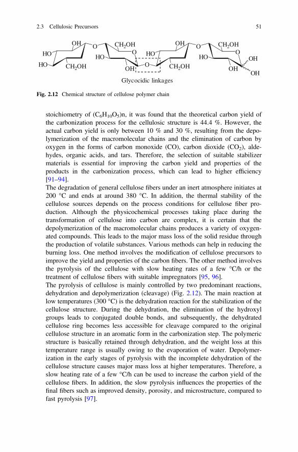
stoichiometry of (C6H10O5)n, it was found that the theoretical carbon yield ofthe carbonization process for the cellulosic structure is 44.4 %. However, theactual carbon yield is only between 10 % and 30 %, resulting from the depo-lymerization of the macromolecular chains and the elimination of carbon byoxygen in the forms of carbon monoxide (CO), carbon dioxide (CO2), alde-hydes, organic acids, and tars. Therefore, the selection of suitable stabilizermaterials is essential for improving the carbon yield and properties of theproducts in the carbonization process, which can lead to higher efficiency[91–94].The degradation of general cellulose fibers under an inert atmosphere initiates at200 °C and ends at around 380 °C. In addition, the thermal stability of thecellulose sources depends on the process conditions for cellulose fiber pro-duction. Although the physicochemical processes taking place during thetransformation of cellulose into carbon are complex, it is certain that thedepolymerization of the macromolecular chains produces a variety of oxygen-ated compounds. This leads to the major mass loss of the solid residue throughthe production of volatile substances. Various methods can help in reducing theburning loss. One method involves the modification of cellulose precursors toimprove the yield and properties of the carbon fibers. The other method involvesthe pyrolysis of the cellulose with slow heating rates of a few °C/h or thetreatment of cellulose fibers with suitable impregnators [95, 96].The pyrolysis of cellulose is mainly controlled by two predominant reactions,dehydration and depolymerization (cleavage) (Fig. 2.12). The main reaction atlow temperatures (300 °C) is the dehydration reaction for the stabilization of thecellulose structure. During the dehydration, the elimination of the hydroxylgroups leads to conjugated double bonds, and subsequently, the dehydratedcellulose ring becomes less accessible for cleavage compared to the originalcellulose structure in an aromatic form in the carbonization step. The polymericstructure is basically retained through dehydration, and the weight loss at thistemperature range is usually owing to the evaporation of water. Depolymer-ization in the early stages of pyrolysis with the incomplete dehydration of thecellulose structure causes major mass loss at higher temperatures. Therefore, aslow heating rate of a few °C/h can be used to increase the carbon yield of thecellulose fibers. In addition, the slow pyrolysis influences the properties of thefinal fibers such as improved density, porosity, and microstructure, compared tofast pyrolysis [97].
OOH
HO
HO CH2OH
HO
O CH2OH
OH
OOH
HO
O CH2OH
HO
O CH2OH
OHOH
OH
Glycocidic linkages
Fig. 2.12 Chemical structure of cellulose polymer chain
2.3 Cellulosic Precursors 51

2. Carbonization and graphitizationAs shown in Fig. 2.13, the first H2O dehydration occurs between 25 and 150 °C(Stage I), and the physical desorption of water and dehydration of the cellulosicunit occur between 150 and 240 °C (Stage II). This leads to the formation of thedouble-bonded intermediates [98]. Carbonization of cellulose refers to theconversion process from this depolymerized structure into graphite-like layersthrough repolymerization. The process begins at approximately 300 °C andcontinues up to 900 °C, as shown in the Stages III and IV of Fig. 2.13. The basicmicrostructure of the carbon is formed during the Stage III [82]. As shown inFig. 2.13, the thermal cleavage of the glycosidic linkage and the scission of etherbonds occur over the range 240–400 °C. Moreover, depolymerization tomonosaccharide derivatives occurs during this stage of carbonization. Then,these intermediates form aromatic structures, releasing gases containing non-carbon atoms (O, H) [99]. The carbonaceous residue is converted into a moreordered carbon structure through heat treatment between 400 and 900 °C underan inert atmosphere. The full mechanism of aromatization related to the gra-phitic products is still unknown, owing to the complex characterization of thecellulose decomposition and existence of many competing reactions during thedifferent stages of carbonization.The heat treatment up to 900 °C causes the formation of semiordered carbo-naceous structures under an inert atmosphere. After this stage, the carbonizedfibers can be treated with heat at higher temperatures to initiate graphitization. Ingeneral, graphitization is carried out under stress at 900–3,000 °C to obtainhigh-modulus fibers through the development of an enhanced order of thegraphene stacks, both laterally between the layers (crystallographic register) andin terms of the preferred orientation along the fiber axis. The Young’s modulusis increased by the increasing treatment temperature, if the graphitization isconducted under tension. After graphitization, the carbon content of the fibersusually increases to above 99 %, and the fiber density increases resulting fromthe growth of crystallites [100].
2.4 Pitch Precursors
Pitches are complex blends of polyaromatic molecules and heterocyclic com-pounds, which can be used as precursors of carbon fibers or carbon fillers in carboncomposites. These pitches can contain more than 80 % carbon, and the compositionof a pitch varies with the source tar and processing conditions [101]. In addition,these pitches can be obtained from one of several sources mentioned below:
1. Petroleum refining, normally called bitumen, or asphalt2. Destructive distillation of coal3. Natural asphalt, e.g., from Trinidad4. Pyrolysis of PVC
52 2 Precursors and Manufacturing of Carbon Fibers

OCH2OH
H
OH
H OH
O
H
O
OH
H
CH2OH
H
HO
H
OO
n
H2O dehydration
OCH2OH
H
OH
H OH
O
H
O
H
H
CH2OH
H
O
H
OO
n
OCH2OH
H
OH
H OH
O
H
O
H
H
CH2OH
H
OH
H
OO
n
[Cell-OH]-H2O
Stage I25~150oC-H2O
150~240oCcleavage
Stage II
240~400oCThermal scissionStage III
OCH2
H
OH
H OH
H
O
OH
O
H
H
CH2OH
H
O
H
O
HHO
H
H2O dehydration
240~400oC-H2O
O
H
CH2OH
H
O
H
O
H
HO
CH2
H
OH
H OH
H
HO
OH
CarbonaceousIntermediates
Dehydration+
ThermalCleavage
Levoglucosan
Tar Stage IV
1. Thermal scissionC=O and C-O bonds
2. Formation of H2O,CO2, CO, etc
All carbon residuesaromaiczation
>700oC
Graphite like layers
Fig. 2.13 Reactions involved in conversion of cellulose into carbon fibers
2.4 Pitch Precursors 53

As mentioned above, the natural pitches are produced by the refining of petro-leum and destructive distillation of coal, while the synthetic pitches are produced bythe pyrolysis of synthetic polymers. Generally, among the prepared pitches usingseveral sources, the petroleum pitch and coal pitch are widely used in the pro-duction of carbon fibers [102].
In terms of the components of pitch, Riggs et al. considered that the pitch iscomposed of four main classes of chemical compounds [103].
1. Saturates: Low molecular weight aliphatic compounds2. Naphthene aromatics: Low molecular weight aromatics and saturated ring
structures3. Polar aromatics: Higher molecular weight and more heterocyclic in nature4. Asphaltenes: Highest molecular weight fraction in pitch with the highest aro-
maticity and thermally most stable
The compositions of various oils and pitches are listed in Table 2.4. Severalresearchers have confirmed that the asphaltene-rich materials are the most suitablefor conversion into carbon fibers.
2.4.1 Petroleum Pitch Precursors
Petroleum pitch can be obtained from various sources such as heavy residueobtained from a catalytic cracking process and steam cracker tar—a by-product ofthe steam cracking of naphtha or gas oils to produce ethylene or any residues fromcrude oil distillation or refining [104]. Many methods can be used for the pro-duction of pitch and are based on an initial refining process, which can includeeither one method or combination of several treatment methods listed below:
1. Prolonged heat treatment to advance the molecular weight of the components2. Air bowing at approximately 250 °C3. Steam stripping and application of vacuum to remove low boiling components4. Distillation
Table 2.4 Compositions of various oils and pitches
Compound Asphaltene(%)
Polararomatic(%)
Naphthenearomatic(%)
Saturate(%)
Softeningpoint (°C)
Carbon black oil 2.5 10.6 69.0 17.9
EXXON (DAU)bottoms (refinerysludge)
14.5 41.1 18.1 26.3 29
Ashland 240petroleum pitch
64.4 8.6 25.4 1.6 119
Ashland 260petroleum pitch
82.7 5.9 11.4 0.0 177
54 2 Precursors and Manufacturing of Carbon Fibers

In common with the coal tar pitch, the chemical and physical characteristics ofpetroleum pitch are dependent on the process and conditions employed, especiallythe process temperature and heat treatment time. Generally, longer times and highertemperatures produce pitches with increased aromaticity and higher anisotropiccontents. The petroleum pitches are usually less aromatic compared to the coal tarpitch [105].
2.4.2 Coal Tar Pitch Precursors
Coal tar is a by-product of the coking of bituminous coals to produce cokes [106].The metallurgical cokes are produced at high temperatures (between 900 and1,100 °C), but it produces smokeless fuels at lower temperatures (approximately600 °C). The low-temperature process affords a smaller amount of tar compared tothe high-temperature process. Coal tar pitch is obtained from the coal tar usingdistillation and heat treatment processes. The pitch is the residue, which follows theremoval of the heavy (creosote or anthracene) oil fractions. The pitches are complexmixtures containing many different individual organic compounds, and the precisecompositions and properties vary according to the source of the tar and method ofremoval of low molecular weight fractions. Smith et al. [107] and Guigon et al.[108] reported that roughly two-thirds of the compounds isolated hitherto from thecoal tar pitch are aromatic, and the rest are heterocyclic. Most of the compounds aresubstituted with the methyl group. The majority of the coal tar pitch componentscontain between three and six rings, having boiling points over the range340–550 °C. Table 2.5 lists the major aromatic hydrocarbon compounds, whichhave been quantitatively found in a typical coal tar pitch [106–109].
2.4.3 Preparation Methods of Pitch-Based Precursors
1. Preparation methods of petroleum pitchMany petroleum products are referred to as “pitch” by the petroleum industry.This could cause considerable confusion outside the refining community. Inmost cases, the different types of petroleum pitch exist as black solids at roomtemperature. The individual characteristics of the petroleum pitches vary withthe functions of the feedstock and specific processes used in their manufacture.Feedstock can range from being predominantly aliphatic to predominantlyaromatic-type chemical structures. A reaction step is used to generate and/orconcentrate the large molecules typically observed in petroleum pitch. The mostcommon processes used to generate petroleum pitches are either singular pro-cesses or a combination of: (a) solvent deasphalting, (b) oxidation, and (c)thermal processes [110].
2.4 Pitch Precursors 55

Solvent deasphalting is used to separate the fractions of various heavy oils. Itinvolves mixing the feedstock with a paraffinic solvent such as propane, butane,or pentane. The mixing of the feedstock with these light paraffinic solventscauses the precipitation of molecules with higher molecular weights and aro-maticities. The chemical and physical properties of this type of petroleum pitchare more closely associated with the asphalt cements used for paving roads.Typical properties include specific gravity of approximately 1.0 g/cc at 60 °F,with the chemical composition containing significant amounts of nonaromatichydrocarbons and high levels of iron, nickel, and vanadium [111].Various grades of pitch can be produced by the oxidation of heavy petroleumhydrocarbons. Although oxygen is used in the process, the products typically donot contain significant amounts of oxygen. During this reaction, the presence of
Table 2.5 Aromatic hydrocarbon components present in coal tar pitch
Acenaphthene Fluorene Anthracene Phenanthren
Fluoranthene Pyrene
CH3
Methylphenanthrene Chrysene
Benz-(a)-anthracene Benzo-(a)-pyrene 3, 4, 8,10-Dibenzopyrene
Coronene Picene
56 2 Precursors and Manufacturing of Carbon Fibers

oxygen is successful in generating free radicals, which induce the polymeriza-tion reactions. The chemical properties of these products will depend upon thestarting material and degree of reaction, but the pitches produced typically havelow coking values and high viscosities [112].Thermal processing is used to produce the petroleum pitch, as noted in severalpatents. Thermal processing has traditionally been used to produce the highspecific gravity and aromatic petroleum pitches referred to in the introduction ofthis chapter. The thermal processes typically employ heat treatment tempera-tures over the range 300–480 °C. A typical schematic for producing thepetroleum pitch from crude oil using thermal processing is shown in Fig. 2.14.
2. Preparation methods of coal tar pitchCoal tar is a by-product of the coking of coal, used to produce metallurgicalcoke [113]. Coal is heated to approximately 1,100 °C in a coke oven to producecoke (the primary product) and by-products such as coke oven gas, coal tar lightoil, and coal tar. The typical yields are 70 % solid products and 30 % liquidproducts. The yield of coal tar, the feedstock for producing coal tar pitch, from aton of coal is 30–45 L (8–12 gallons). Coal tar pitch has several uses, but themajority of the pitch produced is used as a binder for petroleum coke to produce
Fig. 2.14 Schematic for the manufacturing process of petroleum pitch from crude oil
2.4 Pitch Precursors 57
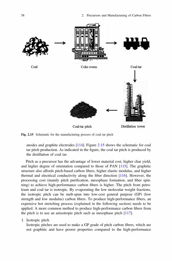
anodes and graphite electrodes [114]. Figure 2.15 shows the schematic for coaltar pitch production. As indicated in the figure, the coal tar pitch is produced bythe distillation of coal tar.
Pitch as a precursor has the advantage of lower material cost, higher char yield,and higher degree of orientation compared to those of PAN [115]. The graphiticstructure also affords pitch-based carbon fibers, higher elastic modulus, and higherthermal and electrical conductivity along the fiber direction [116]. However, theprocessing cost (mainly pitch purification, mesophase formation, and fiber spin-ning) to achieve high-performance carbon fibers is higher. The pitch from petro-leum and coal tar is isotropic. By evaporating the low molecular weight fractions,the isotropic pitch can be melt-spun into low-cost general purpose (GP) (lowstrength and low modulus) carbon fibers. To produce high-performance fibers, anexpensive hot stretching process (explained in the following section) needs to beapplied. A more common method to produce high-performance carbon fibers fromthe pitch is to use an anisotropic pitch such as mesophase pitch [117].
1. Isotropic pitchIsotropic pitches are used to make a GP grade of pitch carbon fibers, which arenot graphitic and have poorer properties compared to the high-performance
Fig. 2.15 Schematic for the manufacturing process of coal tar pitch
58 2 Precursors and Manufacturing of Carbon Fibers
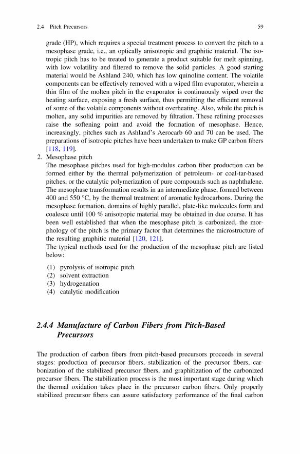
grade (HP), which requires a special treatment process to convert the pitch to amesophase grade, i.e., an optically anisotropic and graphitic material. The iso-tropic pitch has to be treated to generate a product suitable for melt spinning,with low volatility and filtered to remove the solid particles. A good startingmaterial would be Ashland 240, which has low quinoline content. The volatilecomponents can be effectively removed with a wiped film evaporator, wherein athin film of the molten pitch in the evaporator is continuously wiped over theheating surface, exposing a fresh surface, thus permitting the efficient removalof some of the volatile components without overheating. Also, while the pitch ismolten, any solid impurities are removed by filtration. These refining processesraise the softening point and avoid the formation of mesophase. Hence,increasingly, pitches such as Ashland’s Aerocarb 60 and 70 can be used. Thepreparations of isotropic pitches have been undertaken to make GP carbon fibers[118, 119].
2. Mesophase pitchThe mesophase pitches used for high-modulus carbon fiber production can beformed either by the thermal polymerization of petroleum- or coal-tar-basedpitches, or the catalytic polymerization of pure compounds such as naphthalene.The mesophase transformation results in an intermediate phase, formed between400 and 550 °C, by the thermal treatment of aromatic hydrocarbons. During themesophase formation, domains of highly parallel, plate-like molecules form andcoalesce until 100 % anisotropic material may be obtained in due course. It hasbeen well established that when the mesophase pitch is carbonized, the mor-phology of the pitch is the primary factor that determines the microstructure ofthe resulting graphitic material [120, 121].The typical methods used for the production of the mesophase pitch are listedbelow:
(1) pyrolysis of isotropic pitch(2) solvent extraction(3) hydrogenation(4) catalytic modification
2.4.4 Manufacture of Carbon Fibers from Pitch-BasedPrecursors
The production of carbon fibers from pitch-based precursors proceeds in severalstages: production of precursor fibers, stabilization of the precursor fibers, car-bonization of the stabilized precursor fibers, and graphitization of the carbonizedprecursor fibers. The stabilization process is the most important stage during whichthe thermal oxidation takes place in the precursor carbon fibers. Only properlystabilized precursor fibers can assure satisfactory performance of the final carbon
2.4 Pitch Precursors 59

fiber product. Other processes such as surface treatment, sizing, and winding areidentical to the processing of PAN-based carbon fibers.
The typical manufacturing steps for the production of carbon fibers from pitch-based precursors are listed below:
1. Production of precursor fibers by melt spinning [122]Melt spinning involves three steps: melting the precursor, extrusion through aspinneret capillary, and drawing the fibers as they cool. Many investigators haveconcluded that this process is the primary source of structure in the mesophasepitch-based carbon fibers and that thermal treatment only reinforces this struc-ture. The effects of melt spinning conditions on the structure and properties ofcarbon fibers will be discussed in this section.Several process variables are important in determining the fibers’ potential fordeveloping an ordered graphitic structure. The first is melt temperature. Eachmesophase has a range of temperature over which the melt spinning is possible.Spinning at temperatures below this range results in high viscosities and brittlefracture during drawdown, while at temperatures above this range, thermaldegradation of the pitch and dripping owing to low viscosity occur. The vis-cosities of all the mesophases are highly dependent upon temperature, as shownin Fig. 2.16; therefore, the temperature range for successful melt spinning isquite narrow. Using the AR mesophase, Mochida found that decreasing the meltspinning temperature by even 15° resulted in a fourfold increase in viscosityand, in turn, significant decreases in the tensile strength and Young’s modulus.It was, therefore, concluded that a low melt viscosity was necessary for theproduction of high-quality carbon fibers.
2. Stabilization of precursor fibersAnalogous to the PAN precursor fibers, the pitch fibers are either infusibilized oroxidized in air at elevated temperatures before being exposed to the final high-
Fig. 2.16 Schematic of meltspinning process forproduction of precursor fibers
60 2 Precursors and Manufacturing of Carbon Fibers

temperature carbonization treatment. The oxidization temperature should bebelow the fiber softening point to keep the orientated structure. Depending onthe composition, the mesophase pitch precursor is stabilized in air at250–350 °C for a duration ranging from 30 min to several hours. There has beenno consensus hitherto on the purpose of the fiber stretching in this step. Theoxidized pitch molecules contain ketone, carbonyl, and carboxyl groups, whichlead to the stronger hydrogen bonding between the adjacent molecules. Theintroduction of oxygen containing groups and formation of hydrogen bondingbetween the molecules facilitate the three dimensional cross-linking, but hinderthe growth of crystallites. Iodine has been used to reduce the stabilization timeand increase the carbon yield of carbon fibers from the natural pitch. In a patentby Sasaki and Sawaki [123], the pitch fiber was soaked in a methanol solution ofiodine till at least 0.05 wt. % of iodine was imbibed. The fiber was then heatedunder an oxidizing atmosphere for infusibilization. The infusibilization time wasaffected by the amount of imbibed iodine but generally could be completedwithin approximately 10 min [123, 124].
3. Carbonization and graphitization of stabilized precursor fibersStabilized fibers are then carbonized and graphitized. The greatest weight losstakes place in the early stages of carbonization. In order to avoid the defectscreated by the excessive release of volatiles, the fibers are precarbonized for abrief period of 0.5–5 min at 700–900 °C. The carbon fibers can be produced bycarbonizing the stabilized fibers to 1,500–1,800 °C. Bright and Singer [125]reported that because of the degradation of the structure, the modulus decreasedat temperatures up to approximately 1,000 °C, but increased significantly uponfurther increase in temperature. The carbon fibers can be graphitized at tem-peratures close to 3,000 °C for enhanced Young’s modulus. Barr et al. [126]have shown that increasing the heat treatment temperature could increase thepreferred alignment of the crystalline lamellae.Although graphite layers are aligned along the fiber axis, the transverse struc-tures of the carbon fibers can be different. The velocity gradients orient thelayers radially, circumferentially, or randomly. It has been reported that a radialcrack can form in the mesophase carbon fibers with layer planes distributedradially. The alignments in the precursor fiber are retained in the resultantcarbon fiber. Therefore, carbon fiber strength could be improved by adjustingthe microstructure in the precursor fiber. Research has shown that the flawsensitivity of mesophase carbon fibers is reduced by varying the microstructureof the pitch precursor fibers. The microstructure can be modified by changingthe flow profiles during melt spinning. A radial cross section is usually formedthrough the laminar flow of the pitch melt. Petoca Oil Company has employedagitation in the spinneret to impart a randomized distribution for the foldedgraphene layer planes in the transverse direction. The agitation created a tur-bulent flow and the resultant carbon fibers showed increased tensile strength.The turbulent flow can also be obtained by different die designs because the flowbehavior heavily depends on the shape of the spinneret. Spinnerets containing
2.4 Pitch Precursors 61

sections with different diameters have shown to be able to change the fibermicrostructure. Because melt flow is dependent on melt viscosity, the change inthe microstructure can also be obtained simply by changing the spinning tem-perature. Otani and Oya [127] have shown that when the spinning temperaturewas raised to above 349 °C, the radial structure changed to either a random typeor radial type, surrounded by an onion-skin-type structure.
2.5 Other Forms of Precursors
Many other polymers have also been investigated for their potential as carbon fiberprecursors [128–137]. In addition to the cellulosic fibers discussed earlier, othernatural fibers have been investigated and considered as the precursors for carbonfibers such as silk, chitosan, and eucalyptus [128–136]. They can lower the pro-duction cost; however, most of them are used for GP carbon fibers, which do notafford strong mechanical properties.
In addition, many linear and cyclic polymers have been investigated as a pre-cursor for the production of carbon fibers, including phenolic polymers, polyace-nephthalene, polyamide, polyphenylene, poly-p-phenylene benzobisthiazole(PBBT), polybenzoxazole, polybenzimidazole, polyvinyl alcohol, polyvinylidenechloride, and polystyrene. Linear precursors require heat stretching to obtain high-performance carbon fibers, and their carbon yields are usually extremely low [137].The polymers with high aromatic content can generally offer a high carbon yieldand in some cases easy stabilization. However, these polymers either have highcosts or do not produce high-performance carbon fibers. Further research needs tobe conducted to reduce the processing cost while improving the mechanicalproperties of the resultant carbon fibers.
2.6 Summary
In this chapter, we have given a brief overview of the precursors and manufacturingof carbon fibers. Among the precursors used for the production of carbon fibers,PAN-based and pitch-based precursors are the most important. A significant amountof work has been done on relating the fiber structure to the properties and translatingthat relationship into production for either reducing cost or increasing fiber prop-erties. However, challenges, including cost reduction, improvement in tensile andcompressive strength, and alternative precursor development, still remain.
Many polymers such as linear and cyclic polymers have been evaluated as low-cost carbon fiber precursor materials. It will open the door for low-cost carbonfibers. However, more research needs to be conducted to optimize the processingconditions to enhance the mechanical properties and carbon yield of the resultantcarbon fibers.
62 2 Precursors and Manufacturing of Carbon Fibers
References
1. O.J. Paranna, Engineering Chemistry, Tata Mcgraw Education (2009) p. 2482. W.T. Sedgwick, H.W. Tyler, A Short History of Science, The Macmillan Company (1969)
p. 1903. T. Roberts, The Carbon Fiber Industry: Global Strategic Market Evaluation 2006–2010,
(Materials Technology Publications, Watford, UK, 2006) pp. 10, 93–1774. J.B. Donnet, R.C. Bansal, Carbon Fibers, 2nd edn. (Marcel Dekker, New York, NY, USA
1990) pp. 1–1455. X. Huang, Mateials 2, 2369 (2009)6. M C. Red, Compos. Manuf., 7, 24 (2006)7. M. Wang, T. Wang, G. Zhao, Int. J. Appl. Environ. Sci. 8, 1547 (2013)8. S. Arbab, A. Zeinolebadi, Polym. Degrad. Stab. 98, 2537 (2013)9. M. Szala, Fullerenes, Nanotubes, Carbon Nanostruct. 21, 879 (2013)
10. M. Thunga, K. Chen, D. Grewell, M.R. Kessler, Carbon, (2013, Article in press)11. D. Sun, R. Ban, P.H. Zhang, G.H. Wu, J.R. Zhang, J.J. Zhu, Carbon 64, 424 (2013)12. J.K. Lin, S. Kubo, T. Yamada, M. Enoki, Y. Uraki, J. Wood Chem. Technol. 34, 111 (2014)13. Y.Z. Wang, S.G. Wang, J.L. Liu, Key Eng. Mater. 575–576, 151 (2014)14. Y. Bai, Z.H. Huang, F. Kang, Carbon 66, 705 (2014)15. M. Vukčević, B. Pejić, A. Kalijadis, I. Pajić-Lijaković, M. Kostić, Z. Laušević, M. Laušević,
Chem. Eng. J. 235, 284 (2014)16. Y. Yao, J. Chen, L. Liu, Y. Dong, A. Liu, J. Mater. Sci. 49, 191 (2014)17. E. Hammel, X. Tnag, M. Trampert, T. Schmitt, K. Mauthner, A. Eder, Carbon 42, 1153
(2004)18. D.L. Chung, Carbon Fiber Composites, (Butterworth-Heinemann, Boston, MA, USA 1994)
pp. 3–6519. M.K. Seo, S.J. Park, Mat. Sci. Eng. B 164, 106 (2009)20. S.S. Chair, O.P. Bahl, R.B. Mathur, Fiber Sci. Technology 15, 153 (1981)21. E. Zussman, X. Chen, W. Ding, L. Calabri, D.A. Dikin, J.P. Quintana, R.S. Ruoff, Carbon
43, 2175 (2005)22. H.C. Shao, H.Y. Xia, G.W. Liu, G.J. Qiao, Z.C. Xiao, J.M. Su, X.H. Zhang, Y.J. Li, J.
Mater. Eng. Perform. (2013, Article in press)23. M.R. Buchmeiser, J. Unold, K. Schneider, E.B. Anderson, F. Hermanutz, E. Frank, A.
Müller, S. Zinn, J. Mater. Chem. A 1, 13154 (2013)24. V. Kuzmenko, O. Naboka, P. Gatenholm, P. Enoksson, Carbon (2013, Article in press)25. G. Saparaga, T. Mikolajczyk, A. Frczek-Szczypta, Fibers Text. East Europe 21, 33 (2013)26. H. Bi, Z. Yin, X. Cao, X. Xie, C. Tan, X. Huang, B. Chen, F. Chen, Q. Yang, X. Bu, X. Lu,
L. Sun, H. Zhang, Adv. Mater. 25, 5916 (2013)27. Y. Aykut, B. Pourdeyhimi, S.A. Khan, J. Mater. Sci. 48, 7783 (2013)28. S. Hu, Y.L. Hsieh, J. Mater. Chem. A 1, 11279 (2013)29. S.H. Park, S.G. Lee, S.H. Kim, J. Mater. Sci. 48, 6952 (2013)30. H.J. Ko, C.U. Park, H.H. Cho, Y.S. Lim, M.J. Yoo, M.S. Kim, Kor. J. Mater. Res. 48, 6952
(2013)31. A. Burkanudeen, G.S. Krishnan, N. Murali, J. Therm. Anal. Calorim. 112, 1261 (2013)32. R. Eslami Farsani, A. Shokuhfar, A. Sedghi, Int. J. Aerospace and Mechanical Eng. 1:4
(2007) 18433. P. Rajalingam, G. Radhakrishnan, JMS-Rev. Macromol. Chem. Phys. C31, 301 (1991)34. E. Fitzer, Carbon 27, 621 (1989)35. R.B. Mathur, O.P. Bahl, J. Mittal, Compos. Sci. Technol. 51, 223 (1994)36. J. Riggs, in Encyclopedia of Polymer Science and Engineering, 2nd edn, vol. 2, eds. by H.F.
Mark, J.I. Kroschwitz (Wiley, New York 1985), p. 1737. E. Fitxer, M. Heine, in Fiber Reinforcements for Composite Myers: Composite Material
Series, vol. 2, ed. by A.R. Bunsell (Elsevier Publishers, Amsterdam, 1988), pp. 73–148
References 63

38. J.B. Donnet, O.P. Bahl, Encyclopedia of Physical Science and Technology, vol. 2 (AcademicPress, New York, 1987), p. 515
39. S. Dalton, F. Heatley, P.M. Budd, Polymer 40, 5531 (1999)40. N. Grassie, R. McGuchan, Eur. Polym. J. 8, 257 (1972)41. G.T. Sivy, M.M. Coleman, Carbon 19, 127 (1981)42. B.N. Frushover, in Acrylic fiber technology and applications, ed. by J.C. Masson, (New
York, Marcel Dekker, 1995) pp. 197-258, Chapter 743. V.A. Bhanu, P. Rangarajan, K. Wiles, M. Bortner, M. Sankarpandian, D. Godshall, T.E.
Glass, A.K. Banthia, J. Yang, G. Wilkes, D. Baird, J.E. McGrath, Polymer 43, 4841 (2002)44. O.P. Bahl, in Carbon fibers 3rd ed, ed. by J.B. Donnet, T.K. Wang, S. Rebouillat, J.C.M.
Peng. New York: Marcel Dekker, (1998) pp. 1–84. Chapter 145. A.K. Gupta, D.K. Paliwal, and P. Bajaj, JMS-Rev. Part C: Polym, Rev., 31, 1 (1991)46. R. Devasia, C.P.R. Nair, K.N. Ninan, Eur Polym J 39, 537 (2003)47. C. Hou, R. Qu, Y. Liang, C. Wang, J. Appl. Polym. Sci. 96, 1529 (2005)48. G. Burillo, A. Chapiro, Z. Mankowski, J. Polym. Sci. Polym. Chem. Edi. 18, 327 (1980)49. L. Boguslavsky, S. Baruch, S. Margel, J. Colloid Interface Sci. 289, 71 (2005)50. P. Bajaj, D.K. Paliwal, A.K. Gupta, J. Appl. Polym. Sci. 49, 823 (1993)51. A. Shindo, Japan Patent Publication No. (1962)4405 (1962), Patent Application No. (1959)
28287 (1959)52. R. Bacon, T.N. Hoses, in High Performance Polymers, Their Origin and Development, ed.
by R.B. Sanymour, G.S. Kirshambaum (Elsevier, New York, 1986), p. 34253. K. Othmer, in Encyclopedia of Chemical Technology, 5th edn., vol 26 CARBON FIBERS,
(Wiley Blackwell, 2004), p. 73054. R. Bacon, M.M. Tang, Carbon 2, 211 (1964)55. J.C. Chen, I.R. Harrison, Carbon 40, 25 (2002)56. V.B. Gupta, V.K. Kothari (eds.), Manufactured Fibre Technology (Chapman and Hall,
London, 1997)57. R.J. Jokarsky, L.E. Ball, M.M. Wu, C.E. Uebele, US Pat 6,114,034 (2000)58. M.C. Paiva, P. Kotasthane, D.D. Edie, A.A. Ogale, Carbon 41, 1339 (2003)59. A. Takaku, J. Shimizu, J. Appl, Polym. Sci 29, 1319 (1984)60. O.P. Bahl, L.M. Manocha, Carbon 12, 417 (1974)61. P.C. Kang, G.Q. Chen, B. Zhang, G.H. Wu, S. Mula, C.C. Koch, Surf. Coat. Tech. 206, 305
(2011)62. D.H. Kim, B.H. Kim, K.S. Yang, Y.H. Bang, S.R. Kim, H.K. Im, J. Kor, Chem. Soc. 55, 819
(2011)63. W. Shen, S. Zhang, Y. He, J. Li, W. Fan, J. Mater. Chem. 21, 14036 (2011)64. V. Sridhar, J.H. Jeon, I.K. Oh, Carbon 49, 222 (2011)65. S.J. Park, Y. Jung, S. Kim, J. Fluorine Chem. 144, 124 (2012)66. Z. Li, J. Wang, Y. Tong, L. Xu, J. J. Mater. Sci. Technol. 28, 1123 (2012)67. Z. Zhang, J.D. Atkinson, B. Jiang, M.J. Rood, Z. Yan, Apll. Cat. B: Environ. 148–149, 573
(2014)68. A. Ju, Z. Liu, M. Luo, H. Xu, M. Ge, J. Polym. Res. 20, 1 (2013)69. Y.X. Yu, B.L. He, L. Li, Adv. Mater. Res. 791, 506 (2013)70. X.C. Wang, L. Zhou, J.W. Wang, Adv. Mater. Res. 815, 827 (2013)71. L.H. Peebles, Carbon Fiber—Formation, Structure, and Properties, Boca Raton (CRC
Press, LA, 1995)72. M.S.A. Rahaman, A.F. Ismail, A. Mustafa, Polym. Degrad. Stab. 92, 1421 (2007)73. J. Mittal, R.B. Mathur, O.P. Bahl, M. Inagaki, Carbon 36, 893 (1998)74. N. Yusof, A.F. Ismail, J. Anal. Appl. Pyrolysis 93, 1 (2012)75. J. Bromley, in Proceedings of the International Conference on Carbon Fibres, their
Composites and Applications, (Plastic Institute, London 1971) p. 376. L.T. Drzal, M.J. Rich, P.F. Lloyd, J. Adhesion 16, 1 (1983)77. A. Bismarck, M.E. Kumru, J. Springer, J. Simitzis, Appl. Surf. Sci. 143, 45 (1999)78. T.H. Cheng, J. Zhang, S. Yumitori, F.R. Jones, C.W. Anderson, Composites 25, 661 (1994)
64 2 Precursors and Manufacturing of Carbon Fibers

79. R. Bacon, US Pat 2,957,756 (1959)80. W.A. Schalamon, R. Bacon, US Pat 3,716,331 (1973)81. C.E. Ford, C.V. Mitchell, in Union Carbide Corp Fibrous Graphite, US Patent 3,107,152
(1963)82. R. Bacon, M.M. Tang, Carbon 2, 221 (1964)83. O. Paris, C. Zollfrank, G.A. Zickler, Carbon 43, 53 (2005)84. M.M. Tang, R. Bacon, Carbon 2, 211 (1964)85. S.L. Strong, J. Mater. Sci. 9, 993 (1974)86. Q. Wu, D. Pan, Text. Res. J. 72, 405 (2002)87. B. Richard, L.A. Millington, C. Robert, US Pat 3,322,489(1967)88. J.G. Cook, in Handbook of Textile Fibres: Volume 2: Man-Made Fibres, (Woodhead
Publishing, 1984) pp. 82, 10089. H.L. Needles, Textile Fibers, Dyes, Finishes, and Processes (Noyes Publications, Park
Ridge, New Jersey, 1986), p. 4690. R. Bacon, Carbon fibers from Rayon precursors, in Chemistry and Physics of Carbon, vol. 9,
ed. by P.L. Walker Jr, P.A. Thrower (Marcel Dekker, New York, 1973), pp. 1–10291. X. Huang, Materials 2, 2369 (2009)92. F. Zeng, D. Pan, N. Pan, J. Inorg. Org. Polym. Mater. 15, 261 (2005)93. J.B. Tomlinson, C.R. Theocharis, Carbon 30, 907 (1992)94. D.Y. Kim, Y. Nishiyama, M. Wada, S. Kuga, Cellulose 8, 29 (2001)95. F.J. Kilzer, A Broido Pyrodynamics 2, 151 (1965)96. C.B. Cross, D.R. Ecker, O.L. Stein,US Pat 3,116,975 (1964)97. P.H. Brunner, P.V. Roberts, Carbon 18, 217 (1980)98. J. Scheirs, G. Camino, W. Tumiatti, Eur. Polym. J. 37, 933 (2001)99. J.A. Lie, M.B. Hagg, J. Membr. Sci. 284, 79 (2006)100. X. Huang, Materials 2, 2369 (2009)101. C. Berrueco, P. Álvarez, N. Díez, M. Granda, R. Menéndez, C. Blanco, R. Santamaria, M.
Millan, Fuel, (2011, In Press)102. T. Matsumoto, Pure Appl. Chem. 57, 1553 (1985)103. D.M. Riggs, R.J. Shuford, R.W. Lewis, in Graphite Fibers and Composites, ed by G. Lubin.,
Handbook of Composites (Van Nostrand Reinhold Co., New York, 1982)104. Kureha Co., U.S. Pat., 3,629,379 (1971)105. C. Ungureanu, M. Onciu, D. Timpu, Materiale Plastice 33, 57 (1996)106. F.A. Smith, T.F. Eckle, R.J. Osterholm, R.M. Stichel, Manufacture of coal tar and pitches,
ed. by A.J. Hoiberg, vol. III, Bituminous Materials, (RE Krieger, New York 1966) p. 57107. J.W. Smith, Fuel 45, 233 (1966)108. M. Guigon, A. Overlin, G. Desarmot, Fiber Sci. Tech. 20, 177 (1984)109. J.A. Monge, D.C. la Amoros, A.L. Solano, A. Oya, A. Sakamoto, K. Hoshi, Carbon 35, 1079
(1997)110. M.D. Kiser, D.C. Boyer, U.S. Pat., 0094454 (2004)111. H. McGraw, Concise Encyclopedia of Science and Technology, 6th edn. (McGraw-Hill Inc.,
US, 1989)112. D.C. Boyer, M.D. Kiser, S.E. See, U.S. Patent, 0187337 (2002)113. M. Leavitt, in Technical Support Document for the 2004 Effluent Guidelines Program Plan,
(2004), United State Enviromental Protection Agency, Chapter 6, p. 30114. M. Sahoo, in Canadian Institute of Mining, Metallurgy and Petroleum. Light Metals Section,
ed. by C. Fradet (Canadian Institute of Mining, Metallurgy and Petroleum 1998) p. 450115. E. Mora, C. Blanco, V. Prada, R. Santamarıa, M. Granda, R. Menendez, Carbon 40, 2719
(2002)116. Committee on High Performance Synthetic Fibers for Composites, Commission on
Engineering and Technical Systems, and National Research Council, High-PerformanceSynthetic Fibers for Composites (National Academy Press, Washington, DC, USA 1992)pp. 23, 56–64, 86
References 65

117. L.H. Peebles, Carbon Fibers: Formation, Structure, and Properties (CRC Press Inc., BocaRaton, 1995), p. 29
118. S.M. Zeng, T. Maeda, K. Tokumitsu, J. Mondori, Carbon 31, 413 (1993)119. Y.O. Choi, K.S. Yang, Fibers Polym. 2, 178 (2001)120. M.Z. Ozel, K.D. Bartle, Turk. J. Chem. 26, 417 (2002)121. I.C. Lewis, U.S. Pat., 4,032,430 (1977)122. D.D. Edie, M.G. Dunham, Carbon 27, 647 (1989)123. H. Sasaki T. Sawaki, US Pat., 4948574 (1990)124. C.Q. Yang, Carbon 31, 451 (1993)125. A.A. Bright, L.S. Singer, Carbon 17, 59 (1979)126. J.B. Barr, S. Chwastiak, R. Didchenko, I.C. Lewis, R.T. Lewis, L.S. Singer, Appl. Polym.
Symp. 29, 161 (1976)127. S. Otani, A. Oya, Status report on pitch-based carbon fiber in Japan, in Composites ‘86:
Recent Advances in Japan and the United States, Japan Society for Composite Materials, ed.by K. Kawata, S. Umekawa, A. Kobayashi (Japan Society for Composite Materials, Tokyo,Japan, 1986), pp. 1–10
128. M. Majibur, R. Khan, Y. Gotoh, H. Morikawa, M. Miura, Y. Fujimori, M. Nagura, Carbon45, 1035 (2007)
129. M. Bengisu, E. Yilmaz, Carbohydr. Polym. 50, 165 (2002)130. V. Mottaghitalab, M. Farjad, J. Polym. Eng. 33, 857 (2013)131. E. Rojo, M.V. Alonso, J.C. Domínguez, B.D. Saz-Orozco, M. Oliet, F. Rodriguez, J. Appl.
Polym. Sci. 130, 2198 (2013)132. N. Cordeiro, M. Faria, E. Abraham, L.A. Pothan, Carbohydr. Polym. 98, 1065 (2013)133. X. Zhao, X. Lu, W.T.Y. Tze, J. Kim, P. Wang, ACS Appl. Mater. Interf. 5, 8853 (2013)134. X. He, M.B. Hägg, Chem. Eng. J. 215–216, 440 (2013)135. A.G. Dumanli, A.H. Windle, J. Mater. Sci. 47, 4236 (2012)136. X. He, M.B. Hägg, J. Membr. Sci. 378, 1 (2011)137. J.B. Donnet, R.C. Bansal, Carbon Fibers, 2nd edn. (Marcel Dekker, New York, NY, USA,
1990), pp. 1–145
66 2 Precursors and Manufacturing of Carbon Fibers

http://www.springer.com/978-94-017-9477-0