Precision Modules PSK - CMA/Flodyne/Hydradyne PDFs/BRL-LT/Linear...R999000500 (2015-12) | Precision...
76
Precision Modules PSK Courtesy of CMA/Flodyne/Hydradyne ▪ Motion Control ▪ Hydraulic ▪ Pneumatic ▪ Electrical ▪ Mechanical ▪ (800) 426-5480 ▪ www.cmafh.com
Transcript of Precision Modules PSK - CMA/Flodyne/Hydradyne PDFs/BRL-LT/Linear...R999000500 (2015-12) | Precision...

Precision Modules PSK
Cou
rtes
y of
CM
A/F
lody
ne/H
ydra
dyne
▪ M
otio
n Con
trol
▪ H
ydra
ulic
▪ P
neum
atic
▪ E
lect
rica
l ▪ M
echa
nica
l ▪ (
800)
426
-548
0 ▪
ww
w.c
maf
h.co
m
2 Bosch Rexroth AG Precision Modules PSK | R999000500 (2015-12)
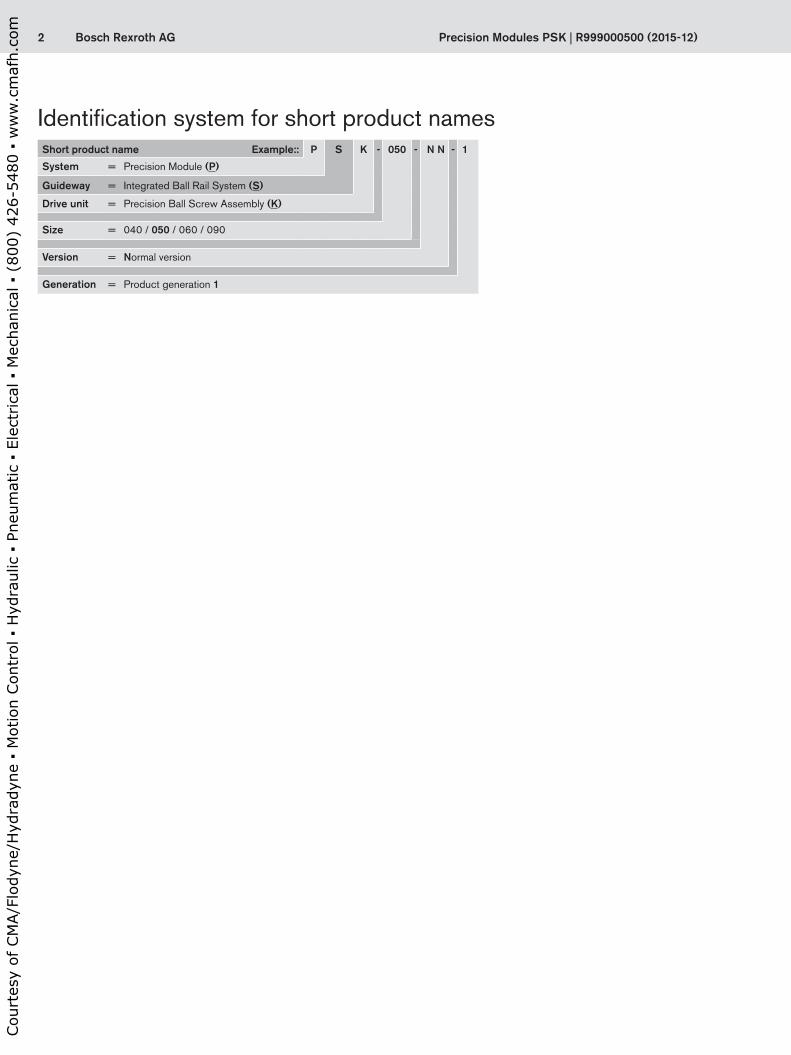
Identification system for short product namesShort product name Example:: P S K - 050 - N N - 1
System = Precision Module (P)
Guideway = Integrated Ball Rail System (S)
Drive unit = Precision Ball Screw Assembly (K)
Size = 040 / 050 / 060 / 090
Version = Normal version
Generation = Product generation 1
Cou
rtes
y of
CM
A/F
lody
ne/H
ydra
dyne
▪ M
otio
n Con
trol
▪ H
ydra
ulic
▪ P
neum
atic
▪ E
lect
rica
l ▪ M
echa
nica
l ▪ (
800)
426
-548
0 ▪
ww
w.c
maf
h.co
m

3Bosch Rexroth AGR999000500 (2015-12) | Precision Modules PSK
Precision Modules PSKProduct overview Product Description 4
Motor selection 6Load capacities and sizes Overview of types with load capacities 8
Dimensions 9Structural Design PSK without cover 10
PSK with cover plate 10PSK with sealing strip 11Attachments for all PSK modules 11
Technical Data General technical data 14Calculations Calculation principles 20
Calculation example 23Accuracy 25
Configuration and ordering, Dimension Drawings 26Precision Module PSK-040 Configuration and ordering 26
Lengths and Hole Spacing 28Dimension Drawings without Cover 29Dimension Drawings with Cover Plate 30Dimension Drawings, Motor Attachment 31
Precision Module PSK-050 Configuration and ordering 32Lengths and Hole Spacing 34Dimension Drawings without Cover 35Dimension Drawings with Cover Plate 36Dimension Drawings with Sealing Strip 37Dimension Drawings, Motor Attachment 38
Precision Module PSK-060 Configuration and ordering 40Lengths and Hole Spacing 42Dimension Drawings without Cover 43Dimension Drawings with Cover Plate 44Dimension Drawings with Sealing Strip 45Dimension Drawings, Motor Attachment 46
Precision Module PSK-090 Components and Ordering Data 48Lengths and Hole Spacing 50Dimension Drawings without Cover 51Dimension Drawings with Cover Plate 52Dimension Drawings with Sealing Strip 53Dimension Drawings, Motor Attachment 54
Attachments and Accessories Switch Mounting Arrangements Overview of switching system 56IndraDyn S Servo Motor MSK 60IndraDyn S Servo Motor MSM 62Motor mounting kits according to customer specification 64Mounting 66
Services and Information Lube Ports 67Documentation 68Operating conditions and usage 70
Normal operating conditions 70Required and supplementary documentation 70
Further Information 71Inquiry/Order Form 72
Cou
rtes
y of
CM
A/F
lody
ne/H
ydra
dyne
▪ M
otio
n Con
trol
▪ H
ydra
ulic
▪ P
neum
atic
▪ E
lect
rica
l ▪ M
echa
nica
l ▪ (
800)
426
-548
0 ▪
ww
w.c
maf
h.co
m

4 Bosch Rexroth AG Precision Modules PSK | R999000500 (2015-12)
Outstanding features
Rexroth Precision Modules are precise, ready-to-install linear motion systems that combine high performance with compact dimensions.Rexroth offers favorable price/performance ratios and fast delivery.
Structural design – Extremely compact and rigid precision steel profile (frame)
with reference edge and integrated Rexroth guideway geometry
– Precision ball screw drive in tolerance grade 7 with zero-backlash nut system
– Aluminum fixed bearing end block with preloaded ball bearings and ball screw journal
– Floating bearing end block with double ball bearings – One or two steel carriages, standard length or long, for
PSK without cover or with cover plate – One aluminum carriage, standard length or long, for PSK
with sealing strip
Attachments – Maintenance-free digital AC servo drives with integrated
brake and attached feedback, or stepping motors – Motor mount and coupling or timing belt side drive for
motor attachment – Adjustable switches over the entire travel range – Aluminum profile mounting duct
Drive controllers and control systems
Product Description
Fixed bearing end block with integrated motor mount
For mounting, maintenance and start-up, see “Instructions for Precision Modules PSK.”
Further highlights
– Extremely stiff and precise miniature drive unit – Optimal travel performance, high load capacities, high
precision and high rigidity due to integrated Rexroth Ball Rail System
– High positioning accuracy and repeatability due to Precision Ball Screw Assembly with zero-backlash nut system
– Repeatability up to 0.005 mm Positioning accuracy up to 0.01 mm Guidance accuracy up to 0.005 mm
– High travel speeds combined with high precision due to Ball Rail Systems, large screw diameters and leads, and double floating bearing
– Rapid mounting and easy axis alignment thanks to machined reference edge on the frame
– Precise alignment and secure mounting of attachments thanks to tapped bores and pin holes in the carriage
– Easy motor attachment via locating feature and fastening threads
– Low-cost maintenance provided by one-point lubrication (grease) for Ball Rail System and Precision Ball Screw Assembly
– Precision Modules in standard lengths for fast delivery
Fixed bearing end block with ball screw journal
Product overview
Cou
rtes
y of
CM
A/F
lody
ne/H
ydra
dyne
▪ M
otio
n Con
trol
▪ H
ydra
ulic
▪ P
neum
atic
▪ E
lect
rica
l ▪ M
echa
nica
l ▪ (
800)
426
-548
0 ▪
ww
w.c
maf
h.co
m

5Bosch Rexroth AGR999000500 (2015-12) | Precision Modules PSK
Internal elements protected by cover plateOne or two steel carriages, standard length or long
Internal elements protected by stainless steel sealing stripAluminum carriage, standard length or long
PSK without cover
Cou
rtes
y of
CM
A/F
lody
ne/H
ydra
dyne
▪ M
otio
n Con
trol
▪ H
ydra
ulic
▪ P
neum
atic
▪ E
lect
rica
l ▪ M
echa
nica
l ▪ (
800)
426
-548
0 ▪
ww
w.c
maf
h.co
m

6 Bosch Rexroth AG Precision Modules PSK | R999000500 (2015-12)
Motor selectionBased on drive controllers and control system
A choice can be made between several different motor/controller combinations to achieve the most cost-efficient solu-tion for each customer application.When sizing the drive, always consider the motor-controller combination.For more information about motors and control systems, see the following Rexroth catalog:
– IndraDrive for Linear Motion Systems
Digital AC servo motors MSK Digital controllers
IndraDrive
Digital controllers
IndraDrive Cs
Digital AC servo motors MSM
Product overview
Cou
rtes
y of
CM
A/F
lody
ne/H
ydra
dyne
▪ M
otio
n Con
trol
▪ H
ydra
ulic
▪ P
neum
atic
▪ E
lect
rica
l ▪ M
echa
nica
l ▪ (
800)
426
-548
0 ▪
ww
w.c
maf
h.co
m

7Bosch Rexroth AGR999000500 (2015-12) | Precision Modules PSK
Precision Modules PSK can be supplied complete with motor, controller and control unit.
Cou
rtes
y of
CM
A/F
lody
ne/H
ydra
dyne
▪ M
otio
n Con
trol
▪ H
ydra
ulic
▪ P
neum
atic
▪ E
lect
rica
l ▪ M
echa
nica
l ▪ (
800)
426
-548
0 ▪
ww
w.c
maf
h.co
m

8 Bosch Rexroth AG Precision Modules PSK | R999000500 (2015-12)
1) All Precision Modules can also be supplied without drive unit.
Type System Guideway Drive unit 1) Size Cover Carriage (carr.) Load capacities
Number C(N)
PSK Precision Module Rail SystemPrecision Ball Screw Assembly
PSK-040Without / cover plate
Standard1 carr. 3 0652 carr. 4 980
PSK-050
Without / cover plate
Standard1 carr. 7 3002 carr. 11 850
Sealing stripStandard 1 carr. 7 300Long 1 carr. 11 850
PSK-060
Without / cover plate
Standard1 carr. 7 3002 carr. 11 850
Long1 carr. 9 0002 carr. 14 620
Sealing stripStandard 1 carr. 9 000Long 1 carr. 14 620
PSK-090
Without / cover plate
Standard1 carr. 21 3002 carr. 34 600
Long1 carr. 27 5002 carr. 44 670
Sealing stripStandard 1 carr. 21 300Long 1 carr. 34 600
Load capacities and sizes
Permissible loads Suitable loads(recommended values)With respect to the desired service life, loads up to about 20% of the charac-teristic dynamic values (C, Mt, ML ) have proved acceptable.
At the same time, the following may not be exceeded:
– maximum permissible loads – permissible drive torque – permissible travel speed
For permissible values, see the “Technical Data” section.
Overview of types with load capacities
Product overview
Cou
rtes
y of
CM
A/F
lody
ne/H
ydra
dyne
▪ M
otio
n Con
trol
▪ H
ydra
ulic
▪ P
neum
atic
▪ E
lect
rica
l ▪ M
echa
nica
l ▪ (
800)
426
-548
0 ▪
ww
w.c
maf
h.co
m

9Bosch Rexroth AG
H
B
C
C
C LC
R999000500 (2015-12) | Precision Modules PSK
Precision Module PSK-040 PSK-050 PSK-060 PSK-090B (mm) 40 50 60 86H (mm) 20 26 33 46L (mm) 100 100 150 340
150 150 200 440200 200 250 540250 250 300 640300 300 400 740350 350 500 840
400 600 940450 700500 800550 900600 940
Standard lengths L
Dimensions
Cou
rtes
y of
CM
A/F
lody
ne/H
ydra
dyne
▪ M
otio
n Con
trol
▪ H
ydra
ulic
▪ P
neum
atic
▪ E
lect
rica
l ▪ M
echa
nica
l ▪ (
800)
426
-548
0 ▪
ww
w.c
maf
h.co
m

10 Bosch Rexroth AG
1
2
3
4
5
6
7
9
8
Precision Modules PSK | R999000500 (2015-12)
1 Fixed bearing end block2 Ball screw with zero-backlash cylindrical single nut3 One or two steel carriages, standard length or long4 Floating bearing end block5 Frame with reference edge and integrated guideway
geometry
6 Cover plate7 One or two carriages, standard length or long8 Carriage plate, aluminum9 Carriage plate guide unit, steel
Structural Design
2 carriages, standard length
1 carriage, long
2 carriages, long
1 carriage, standard length
2 carriages, standard length
1 carriage, long
2 carriages, long
1 carriage, standard length
PSK with cover platePSK without cover
Product overview
Cou
rtes
y of
CM
A/F
lody
ne/H
ydra
dyne
▪ M
otio
n Con
trol
▪ H
ydra
ulic
▪ P
neum
atic
▪ E
lect
rica
l ▪ M
echa
nica
l ▪ (
800)
426
-548
0 ▪
ww
w.c
maf
h.co
m

11Bosch Rexroth AG
10
11
13
1215
14
16
R999000500 (2015-12) | Precision Modules PSK
10 Sealing strip, stainless steel11 One carriage, standard length or long12 Carriage plate, aluminum13 Carriage plate guide unit, aluminum
14 Switches15 Mounting duct16 Switching cam
1 carriage, long
1 carriage, standard length
PSK with sealing strip Attachments for all PSK modules
Cou
rtes
y of
CM
A/F
lody
ne/H
ydra
dyne
▪ M
otio
n Con
trol
▪ H
ydra
ulic
▪ P
neum
atic
▪ E
lect
rica
l ▪ M
echa
nica
l ▪ (
800)
426
-548
0 ▪
ww
w.c
maf
h.co
m

12 Bosch Rexroth AG
1
2
3
1
2
3
4
1
2
1
6
1 6 3 4 5
1 2 3 5
A B
Precision Modules PSK | R999000500 (2015-12)
Motor attachment
Motor attachment with motor mount and couplingA motor can be attached to all Precision Modules by means of a motor mount and coupling.The motor mount serves to fasten the motor to the Precision Module and acts as a closed housing for the coupling. The coupling transmits the motor drive torque free of distortive stresses to the Precision Module’s ball screw journal.
Fixed bearing end block with inte-grated motor mount and coupling1 Motor2 Fixed bearing end block
with integrated motor mount3 Coupling5 Precision module
Structural Design
Fixed bearing end block with attached motor mount and coupling1 Motor3 Coupling4 Fixed bearing end block5 Precision module6 Motor mount
Fixed bearing end block
Version with ball screw journal (A)1 End block with preloaded bearing2 Tapped mounting hole3 Centering feature
Version with integrated motor mount (B)1 End block with integrated motor mount
and preloaded bearing2 Tapped mounting hole3 Centering feature4 Flange form suitable for motor
attachment
Product overview
Cou
rtes
y of
CM
A/F
lody
ne/H
ydra
dyne
▪ M
otio
n Con
trol
▪ H
ydra
ulic
▪ P
neum
atic
▪ E
lect
rica
l ▪ M
echa
nica
l ▪ (
800)
426
-548
0 ▪
ww
w.c
maf
h.co
m

13Bosch Rexroth AG
Fpr
6
5
4
7
1
9
8
5
2
2
9
1
3
2
5
R999000500 (2015-12) | Precision Modules PSK
Motor attachment with timing belt side driveOn Precision Modules PSK-050 and PSK-090 the motor (9) can be attached via a side drive with timing belt.This makes the overall length shorter than when attaching the motor with a motor mount and coupling.The compact, closed housing protects the belt and secures the motor.
The following gear ratios are available:i = 1 : 1i = 1 : 1.5
The timing belt side drive can be mounted in four different directions:
– top, bottom – left, right
1 Precision module2 End cover3 Cover plate4 Drawn, anodized aluminum profile5 Ball screw journal with support
bearing6 Toothed belt7 Pre-tensioning of the toothed belt:
Apply pretensioning force Fpr to motor (Fpr will be indicated on delivery)
8 Belt pulleys9 AC servo motor
Cou
rtes
y of
CM
A/F
lody
ne/H
ydra
dyne
▪ M
otio
n Con
trol
▪ H
ydra
ulic
▪ P
neum
atic
▪ E
lect
rica
l ▪ M
echa
nica
l ▪ (
800)
426
-548
0 ▪
ww
w.c
maf
h.co
m

14 Bosch Rexroth AG
yy
z
z
Precision Modules PSK | R999000500 (2015-12)
General technical dataPrecision Module
Planar moment of inertia
Minimum center-to-center distance lm min
Mass of the linear motion system ms (kg)Without cover, without drive
Without cover, with drive
With cover plate
With sealing stripIy Iz Standard carr. Long carr.
(cm4) (cm4) (mm) (mm)PSK-040 0.892 6.65 50 – 0.0026 · L + mca 0.0028 · L
+ 0.075 + mca
0.0030 · L + 0.089 + mca
–
PSK-050 1.690 13.50 60 – 0.0035 · L + mca 0.0038 · L + 0.179 + mca
0.0041 · L + 0.204 + mca
0.0042 · L + 0.208 + mca
PSK-060 5.380 34.48 60 75 0.0062 · L + mca 0.0069 · L + 0.254 + mca
0.0072 · L + 0.281 + mca
0.0073 · L + 0.272 + mca
PSK-090 22.340 145.80 90 110 0.0125 · L + mca 0.0138 · L + 0.638 + mca
0.0146 · L + 0.726 + mca
0.0147 · L + 0.736 + mca
MassMass calculation without motor and switches.Mass formula:Mass factor (kg/mm) · length L (mm) + mass of all parts of fixed length (kg) + moved mass of system mca (kg)
Modulus of elasticity E E = 210,000 N/mm2
Dynamic characteristics
Precision Module
Type of cover
Carriage (carr.) Guideway Ball screw Fixed bearingNumber Dynamic load capacity
Dynamic load moments Size Dynamic
load capacityDynamic
load capacityC
(N)Mt
(Nm)ML
(Nm)d0 x P C
(N)C
(N)PSK-040 W/o and
w/plateStandard 1 carr. 3 065 43.1 14.8 6 x 1 900 820
2 carr. 4 980 70.0 2.49 x lm 6 x 2 890 820PSK-050 W/o and
w/plateStandard 1 carr. 7 300 150.0 35 8 x 2.5 2 200 1 600
2 carr. 11 850 244.0 5.93 x lm 8 x 2.5 2 200 1 600Strip Standard 1 carr. 7 300 150.0 35 8 x 2.5 2 200 1 600
Long 1 carr. 11 850 244.0 356 8 x 2.5 2 200 1 600PSK-060 W/o and
w/plateStandard 1 carr. 7 300 170.0 35 12 x 2 2 240 4 000
2 carr. 11 850 276.0 5.93 x lm 12 x 2 2 240 4 000Long 1 carr. 9 000 210.0 60 12 x 5 3 800 4 000
2 carr. 14 620 341.0 7.31 x lm 12 x 5 3 800 4 000Strip Standard 1 carr. 9 000 210.0 60 12 x 10 2 500 4 000
Long 1 carr. 14 620 341.0 541 12 x 10 2 500 4 000PSK-090 W/o and
w/plateStandard 1 carr. 21 300 710.0 150 16 x 5 12 300 13 400
2 carr. 34 600 1153.0 17.3 x lm 16 x 5 12 300 13 400Long 1 carr. 27 500 910.0 270 16 x 10 9 600 13 400
2 carr. 44 670 1478.0 22.34 x lm 16 x 10 9 600 13 400Strip Standard 1 carr. 21 300 710.0 150 16 x 16 6 300 13 400
Long 1 carr. 34 600 1153.0 1557 16 x 16 6 300 13 400
lm = center-to-center distance between carriages (mm)d0 = screw diameter (mm)P = screw lead (mm)carr. = carriage(s) (mm)mca = moved mass of system (kg)
Maximum acceleration: amax = 27 m/s2
Ambient temperature 0 °C ... 40 °C
Technical Data
Cou
rtes
y of
CM
A/F
lody
ne/H
ydra
dyne
▪ M
otio
n Con
trol
▪ H
ydra
ulic
▪ P
neum
atic
▪ E
lect
rica
l ▪ M
echa
nica
l ▪ (
800)
426
-548
0 ▪
ww
w.c
maf
h.co
m

15Bosch Rexroth AG
y
x
z
M z max
M L /
Mx max
l m
Mt/
Fz max
My max
ML /F
y max
R999000500 (2015-12) | Precision Modules PSK
Note on dynamic load capacities and momentsDetermination of the dynamic load capacities and moments is based on a travel life of 100,000 m.Often only 50,000 m are actually stipulated.For comparison: Multiply values C, Mt and ML from the table by 1.26.
Moved mass of system mca
Maximum permissible loadsThe maximum permissible forces (Fy max, Fz max) and moments (Mx max, My max, Mz max) are equal to half the dynamic characteristics (C, Mt, ML).
Precision Module
Carriage Moved mass of system mca (kg)Without cover, without drive
Without cover, with drive
With cover plate With sealing strip
1 carr. 2 carr. 1 carr. 2 carr. 1 carr. 2 carr. 1 carr. PSK-040 Standard 0.08 0.17 0.09 0.18 0.14 0.28 –PSK-050 Standard 0.20 0.40 0.22 0.42 0.29 0.56 0.20
Long – – – – – – 0.37PSK-060 Standard 0.25 0.49 0.27 0.52 0.38 0.73 0.33
Long 0.34 0.69 0.37 0.71 0.51 1.00 0.58PSK-090 Standard 0.77 1.54 0.85 1.62 1.09 2.10 0.80
Long 1.04 2.08 1.11 2.15 1.43 2.79 1.40
Suitable loads(recommended values)With respect to the desired service life, loads up to about 20% of the charac-teristic dynamic values (C, Mt, ML) have proved acceptable.At the same time, the following may not be exceeded:
– maximum permissible loads – permissible drive torque – permissible travel speed – maximum permissible acceleration
lm = center-to-center distance between carriages (mm)
carr. = carriage(s) (mm)
Cou
rtes
y of
CM
A/F
lody
ne/H
ydra
dyne
▪ M
otio
n Con
trol
▪ H
ydra
ulic
▪ P
neum
atic
▪ E
lect
rica
l ▪ M
echa
nica
l ▪ (
800)
426
-548
0 ▪
ww
w.c
maf
h.co
m

16 Bosch Rexroth AG
0,05
0,15
0,10
0,30
0,00100 150 200 250 300 350
0,20
0,25
Mp
N()
m
L (mm)
6x1
100
0,4
0,2
0,6
0,8
0,0200 300 400 500 600
N()
m
L (mm)
Mp
0,5
1,0
1,5
2,0
2,5
3,0
3,5
0,0200 300 400 500 600 700 800 900100
L (mm)
N()
m 12x5
12x2
Mp
12
3
4
5
8
7
6
0390 440 490 540 590 690640 740 790 840 890 940
N()
m
L (mm)340
16x10
16x5
Mp
PSK-060
PSK-090
PSK-040
PSK-050
Precision Modules PSK | R999000500 (2015-12)
Maximum permissible drive torque at the screw journal Mp
The values shown for Mp are applicable under the following conditions:
– Horizontal operation – Ball screw journal without keyway – No radial load on ball screw shaft
Consider the rated torque of the cou-pling used!
L = PSK length (mm)Ball screw = ball screw size: d0 x Pd0 = screw diameter (mm)P = lead (mm)
Ball screw 12x10
Ball screw 16x16
Ball screw 6x2
Ball screw 8x2,5
Technical Data
General technical data
Cou
rtes
y of
CM
A/F
lody
ne/H
ydra
dyne
▪ M
otio
n Con
trol
▪ H
ydra
ulic
▪ P
neum
atic
▪ E
lect
rica
l ▪ M
echa
nica
l ▪ (
800)
426
-548
0 ▪
ww
w.c
maf
h.co
m

17Bosch Rexroth AG
100 150 200 250 300 350
0,4
0,3
0,2
0,1
0
v max
( s/
m)
L (mm)
6x1
300 400 500 600200L (mm)
100
0,3
0,2
0,1
0
v max
( s/
m)
300 400 500 600 700 800200 900L (mm)
100
( s/
m)
1,81,61,41,21,00,80,60,40,2
0
16x10
16x5
v max
300 400 500 600 700 800200 900L (mm)
100
v max
(s/
m)
1,2
1,0
0,8
0,6
0,4
0,2
0
12x5
12x2
PSK-060
PSK-050
PSK-090
PSK-040
R999000500 (2015-12) | Precision Modules PSK
Maximum permissible linear speed vmax
Consider the motor speed!
L = PSK length (mm)Ball screw = ball screw size: d0 x Pd0 = screw diameter (mm)P = lead (mm)
Ball screw 6x2
Ball screw 8x2,5
Ball screw 12x10
Ball screw 16x16
Cou
rtes
y of
CM
A/F
lody
ne/H
ydra
dyne
▪ M
otio
n Con
trol
▪ H
ydra
ulic
▪ P
neum
atic
▪ E
lect
rica
l ▪ M
echa
nica
l ▪ (
800)
426
-548
0 ▪
ww
w.c
maf
h.co
m

18 Bosch Rexroth AG Precision Modules PSK | R999000500 (2015-12)
Frictional torque of the linear motion system MRs
Precision Module Frictional torque of the linear motion system MRs (Nm) for carriage versionBall screw sized0 x P
Without cover or with cover plate With sealing stripStandard carr. Long carr. Standard carr. Long carr.
PSK-040 6 x 1 0.033 – – –6 x 2 0.034 – – –
PSK-050 8 x 2.5 0.06 – 0.06 0.07PSK-060 12 x 2 0.10 0.10 0.10 0.11
12 x 5 0.11 0.11 0.11 0.1212 x 10 0.12 0.13 0.13 0.15
PSK-090 16 x 5 0.30 0.30 0.29 0.3116 x 10 0.32 0.32 0.30 0.3416 x 16 0.34 0.36 0.32 0.37
carr. = carriage(s) (mm)d0 = screw diameter (mm)P = screw lead (mm)
d0 = screw diameter (mm)P = screw lead (mm)
MRsd = frictional torque of timing belt side drive at motor journal (Nm)Msd = maximum permissible drive torque of the timing belt side drive (Nm); consider the maximum torque of the motor Mmax
Jsd = mass moment of inertia of timing belt side drive (kgm2)i = timing belt side drive reduction
Motor type MSM 019B MSM 031B / MSM 031C / MSK 030F (mm) 48 64.5MRsd (Nm) 0.10 0.15msd (kg) 0.28 0.65
Msd 2) Jsd Msd
2) Jsd
Gear ratio i i = 1 i = 1.5 i = 1 i = 1.5 i = 1 i = 1.5 i = 1 i = 1.5Belt type 6 AT3 6 AT3 6 AT3 6 AT3 10 AT3 10 AT3 10 AT3 10 AT3Size BS up to L1) up to L1)
d0 x P (mm) (Nm) (Nm) (10–6 kgm2) (10–6 kgm2) (mm) (Nm) (Nm) (10–6 kgm2) (10–6 kgm2)PSK-050 8 x 2.5 450 0.61 0.41 10.7 4.1 — — — — —PSK-060 12 x 2 940 0.79 0.53 10.7 4.1 940 0.79 0.53 34.8 13.1
12 x 5 940 1.31 0.87 800 2.48 1.6512 x 10 940 1.31 0.87 940 2.70 1.80
PSK-090 16 x 5 — — — — — 940 2.87 1.91 41.5 13.416 x 10 — — — 940 2.87 1.9116 x 16 — — — 940 2.87 1.91
Motor type MSM 041B / MSK 040F (mm) 88MRsd (Nm) 0.40msd (kg) 1.45
Msd 2) Jsd
Gear ratio i i = 1 i = 1.5 i = 1 i = 1.5Belt type 16 AT5 16 AT5 16 AT5 16 AT5Size BS up to L1)
d0 x P (mm) (Nm) (Nm) (10–6 kgm2) (10–6 kgm2)PSK-090 16 x 5 940 4.31 2.87 234.4 83.6
16 x 10 940 5.85 3.9016 x 16 940 6.42 4.28
i = timing belt side drive reductionBS = ball Screw Assemblyd0 = screw diameter (mm)P = screw lead (mm)Jsd = mass moment of inertia of timing belt side driveMRsd = frictional torque of timing belt side drive at motor journalMsd = maximum permissible drive torque of the timing belt side drivemsd = mass of timing belt side drive
Motor attachment via timing belt side drive
1) For longer lengths, the permitted drive torque is determined by the length-dependent value Mp of the linear system as given in the graphs ! section “Technical Data”
2) Values for Msd do not take motor torque into account.
Technical Data
General technical data
Cou
rtes
y of
CM
A/F
lody
ne/H
ydra
dyne
▪ M
otio
n Con
trol
▪ H
ydra
ulic
▪ P
neum
atic
▪ E
lect
rica
l ▪ M
echa
nica
l ▪ (
800)
426
-548
0 ▪
ww
w.c
maf
h.co
m

19Bosch Rexroth AG
Js = (kJ fix + k J var . L) . 10–6
R999000500 (2015-12) | Precision Modules PSK
Motor attachment via motormount and coupling
Js = mass moment of inertia of linear motion system (without external load) (kgm2)
kJ fix = constant for fixed-length portion of mass moment of inertia (106 kgm2)
kJ m = constant for mass-specific portion of mass moment of inertia (106 kgm2)
kJ var = constant for variable-length portion of mass moment of inertia (109 kgm)
L = length (mm)
Precision Module
kJ fix kJ var kJ m
Ball screw size
Carriage Without cover Cover plate Sealing strip
d0 x P 1 carr. 2 carr. 1 carr. 2 carr. 1 carr.PSK-040 6 x 1 Standard 0.115 0.117 0.116 0.120 – 0.002 0.025
6 x 2 Standard 0.122 0.131 0.127 0.141 – 0.002 0.101PSK-050 8 x 2,5 Standard 0.533 0.565 0.544 0.587 0.530
0.004 0.158Long – – – – 0.557PSK-060 12 x 2 Standard 0.999 1.024 1.010 1.045 1.005
0.013 0.101Long 1.009 1.043 1.023 1.073 1.03012 x 5 Standard 1.130 1.289 1.200 1.422 1.168
0.011 0.633Long 1.194 1.409 1.282 1.593 1.32712 x 10 Standard 1.643 2.277 1.922 2.808 1.795
0.011 2.533Long 1.897 2.758 2.251 3.492 2.492PSK-090 16 x 5 Standard 4.216 4.703 4.368 5.007 4.184
0.031 0.633Long 4.380 5.039 4.583 5.444 4.56416 x 10 Standard 5.831 7.781 6.439 8.997 5.704
0.031 2.533Long 6.489 9.124 7.300 10.745 7.22416 x 16 Standard 9.213 14.207 10.770 17.319 8.889
0.034 6.485Long 10.899 17.643 12.974 21.793 12.780
Mass moment of inertia of the linear motion system Js referred to the drive journal
Precision Module Coupling datafor motor attachment
Rated torque
McN
Mass moment of inertia
Jc
MassAssembly kit
Motor mount mc
(Nm) (10–6 kgm2) (kg)PSK-040 MSM 019B 0.70 0.12 0.09PSK-050 MSM 019B 1.90 2.10 0.09
MSM 031B 3.70 7.00 0.28MSK 030C 3.70 7.00 0.25
PSK-060 MSM 031B 3.70 7.00 0.30MSK 030C 1.90 2.10 0.15
PSK-090 MSM 031C 10.00 35.00 0.41MSM 041B 9.00 60.00 0.77MSK 030C 10.00 35.00 0.43MSK 040C 9.00 60.00 0.73
Cou
rtes
y of
CM
A/F
lody
ne/H
ydra
dyne
▪ M
otio
n Con
trol
▪ H
ydra
ulic
▪ P
neum
atic
▪ E
lect
rica
l ▪ M
echa
nica
l ▪ (
800)
426
-548
0 ▪
ww
w.c
maf
h.co
m

20 Bosch Rexroth AG
z1
y
x
z
M z
M L /
Mx
Mt/
Fz
Fy My
ML /
Mx
MtFcomb = Fy + Fz + C · + C · + C ·
My
ML
Mz
ML
Precision Modules PSK | R999000500 (2015-12)
Calculation principles
Combined equivalent load on bearing of the linear guide
Fcomb = combined equivalent load on bearing (N)Fy = force in y-direction (N)Fz = force in z-direction (N)Mx = torsional moment (about the x-axis) (Nm)My = torsional moment (about the y-axis) (Nm)Mz = torsional moment (about the z-axis) (Nm)C = dynamic load capacity (N)Mt = dynamic torsional moment load capacity (Nm)ML = dynamic longitudinal moment load capacity (Nm)
(1)
z1 = distance between guideway centerline and top edge of carriage (mm)
z1 (mm)Without cover Cover plate Sealing strip
PSK-040 11 23 –PSK-050 13 27 27PSK-060 17 32 32PSK-090 22 44 44
Calculations
Cou
rtes
y of
CM
A/F
lody
ne/H
ydra
dyne
▪ M
otio
n Con
trol
▪ H
ydra
ulic
▪ P
neum
atic
▪ E
lect
rica
l ▪ M
echa
nica
l ▪ (
800)
426
-548
0 ▪
ww
w.c
maf
h.co
m

21Bosch Rexroth AG
Jex = + JsdJs + Jt
i2
Jex = Js + Jt + Jc
Jt = mex · kJm · 10-6
L = · 105 m CFcomb
3
L h = L
3600 · vm
MR = MRs
MR = + MR sdMRs
i
R999000500 (2015-12) | Precision Modules PSK
C = dynamic load capacity (N)Fcomb = combined equivalent load
on bearing (N)i = timing belt side drive
reduction (–)Jc = mass moment of inertia,
coupling (kgm2)Jex = mass moment of inertia
of mechanical system (kgm2)Js = mass moment of inertia
of linear motion system (without external load) (kgm2)
Jt = translatory mass moment of inertia of external load referred to the drive journal (kgm2)
kJm = constant for mass-specific portion of mass moment of inertia (106 m2)
L = nominal life (m)Lh = nominal life (h)mex = moved external load (kg)MR = frictional torque at motor
journal (Nm)MR sd = frictional torque of timing
belt side drive (Nm)MRs = frictional torque of linear
motion system (Nm)vm = average speed (m/s)
Nominal life Nominal life of the guideway in meters:
Frictional torqueFrictional torque for motor attachment via motor mount and coupling:
Mass moment of inertiafor motor attachment via motor mount and coupling:
for motor attachment via timing belt side drive:
Nominal life of the guideway in hours:
(3)
(4)
(2)
(6)
(7)
Translatory mass moment of inertia of external load referred to the drive journal
(8)
(5)
Frictional torque for motor attachment via timing belt side drive:
Cou
rtes
y of
CM
A/F
lody
ne/H
ydra
dyne
▪ M
otio
n Con
trol
▪ H
ydra
ulic
▪ P
neum
atic
▪ E
lect
rica
l ▪ M
echa
nica
l ▪ (
800)
426
-548
0 ▪
ww
w.c
maf
h.co
m

22 Bosch Rexroth AG
Jdc = Jex + Jbr
Jtot = Jdc + Jm
nmech =vmax · i · 1 000 · 60
P
V = Jdc
Jm
Precision Modules PSK | R999000500 (2015-12)
Mass moment of inertia of the drive train referred to the motor journal
(8)
i = timing belt side drive reduction (–)
Jbr = mass moment of inertia, motor brake (kgm2)
Jdc = mass moment of inertia, drive train (kgm2)
Jex = mass moment of inertia of mechanical system (kgm2)
Jm = mass moment of inertia, motor (kgm2)
Jtot = total mass moment of inertia (kgm2)
nm max = maximum permissible rotary speed of motor with controller (min–1)
nmech = maximum permissible rotary speed of mechanical system (min–1)
P = screw lead (mm)V = ratio of mass moments
of inertia of drive train and motor (–)
vmax = maximum permissible linear speed of mechanical system (m/s)
Application area VHandling ≤ 6.0Machining ≤ 1.5
Mass moment of inertia ratio(9)
Total mass moment of inertia referred to the motor journal (10)
Maximum permissible rotary speed for mechanical system (11)
Condition: nmech < nm max
Calculation principles
Calculations
Cou
rtes
y of
CM
A/F
lody
ne/H
ydra
dyne
▪ M
otio
n Con
trol
▪ H
ydra
ulic
▪ P
neum
atic
▪ E
lect
rica
l ▪ M
echa
nica
l ▪ (
800)
426
-548
0 ▪
ww
w.c
maf
h.co
m

23Bosch Rexroth AG
390 mm
L
m = 20 kg m = 20 kgF = 0 N
R999000500 (2015-12) | Precision Modules PSK
Given data
When sizing the drive, the motor-controller combination must always be considered, as the motor type and performance data (e.g. maximum useful speed and maximum torque) will depend on the controller or control system used.
A mass of 20 kg is to be moved 390 mm at a maximum travel speed of 0.6 m/s.
Estimation of the PSK module length L
Module selected based on the technical data and the connection dimensions:
– PSK-090 without cover and with a standard length steel carriage; motor attachment via integrated motor mount and coupling
– Motor type MSK 030C
Excess travel = 2 . P = 2 . 16 mm = 32 mm (in accordance with the formula given in “PSK-090 Components and Ordering Data”)
Permissible ball screws according to the “Permissible travel speed” chart at vmax = 0.6 m/s: Ball screw 16x10 and 16x16; Ball screw selected: Ball screw 16x10 with vmax = 1 m/sMp = 4.1 Nm with ball screw 16x10 (according to the chart “Maximum permissible drive torque”)
Selection of ball screw:As a general rule:Always choose the lowest lead (resolution, braking distance, length).
Excess travel = 2 . P = 2 . 10 mm = 20 mm Length L = (effective stroke + 2 . excess travel) + 100 mm =
(390 mm + 2 . 20 mm) + 100 mm = 530 mmSelected: Standard length L = 540 mm; hole spacing in frame: 70 mm / 4 . 100 mm / 70 mm
MR = MRsMR = 0.30 Nm (see “Technical Data”)
Calculation of PSK length L
Frictional torque MR
Calculation example
Cou
rtes
y of
CM
A/F
lody
ne/H
ydra
dyne
▪ M
otio
n Con
trol
▪ H
ydra
ulic
▪ P
neum
atic
▪ E
lect
rica
l ▪ M
echa
nica
l ▪ (
800)
426
-548
0 ▪
ww
w.c
maf
h.co
m
24 Bosch Rexroth AG Precision Modules PSK | R999000500 (2015-12)
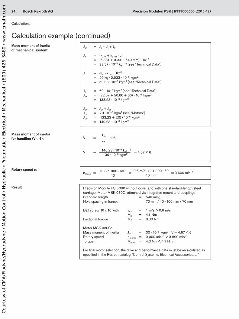
Calculation example (continued)Jex = Js + Jt + Jc
Js = (kJ fix + kJ var · L) = (5.831 + 0.031 · 540 mm) · 10–6
= 22.57 · 10–6 kgm2 (see “Technical Data”)
Jt = mex · kJ m · 10–6
= 20 kg · 2.533 · 10–6 kgm2
= 50.66 · 10–6 kgm2 (see “Technical Data”)
Jc = 60 · 10–6 kgm2 (see “Technical Data”)Jex = (22.57 + 50.66 + 60) · 10–6 kgm2
= 133.23 · 10–6 kgm2
Jdc = Jex + JbrJbr = 7.0 · 10–6 kgm2 (see “Motors”)Jdc = (133.23 + 7.0) · 10–6 kgm2
= 140.23 · 10–6 kgm2
Mass moment of inertia of mechanical system:
Precision Module PSK-090 without cover and with one standard-length steel carriage; Motor MSK 030C, attached via integrated mount and coupling:Standard length L = 540 mm; Hole spacing in frame: 70 mm / 40 · 100 mm / 70 mm
Ball screw 16 x 10 with vmax = 1 m/s > 0.6 m/s Mp = 4.1 Nm Frictional torque MR = 0.30 Nm
Motor MSK 030C:Mass moment of inertia Jm = 30 · 10–6 kgm2 ; V = 4.67 < 6 Rotary speed nm max = 9 000 min–1 > 3 600 min–1 Torque Mmax = 4.0 Nm < 4.1 Nm
For final motor selection, the drive and performance data must be recalculated as specified in the Rexroth catalog “Control Systems, Electrical Accessories, ...”
Mass moment of inertia for handling (V ≤ 6):
Rotary speed n:
Result
140.23 · 10–6 kgm2
30 · 10–6 kgm2
V =Jdc
Jm≤ 6
V = = 4.67 < 6
nmech = = = 3 600 min–1v · i · 1 000 · 6010
0.6 m/s · 1 · 1 000 · 60
10 mm
Calculations
Cou
rtes
y of
CM
A/F
lody
ne/H
ydra
dyne
▪ M
otio
n Con
trol
▪ H
ydra
ulic
▪ P
neum
atic
▪ E
lect
rica
l ▪ M
echa
nica
l ▪ (
800)
426
-548
0 ▪
ww
w.c
maf
h.co
m
25Bosch Rexroth AG
II P1
II P3 P3
246
81012141618
0200 300 400 500 600 700 800 900
L (mm)100
2468
1012141618
0200 300 400 500 600 700 800 900
L (mm)100
R999000500 (2015-12) | Precision Modules PSK
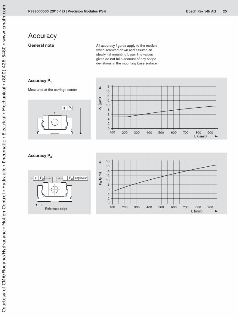
All accuracy figures apply to the module when screwed down and assume an ideally flat mounting base. The values given do not take account of any shape deviations in the mounting base surface.
Accuracy P1
Measured at the carriage center
Accuracy P3
General note
Accuracy
Reference edge
lengthwise
Cou
rtes
y of
CM
A/F
lody
ne/H
ydra
dyne
▪ M
otio
n Con
trol
▪ H
ydra
ulic
▪ P
neum
atic
▪ E
lect
rica
l ▪ M
echa
nica
l ▪ (
800)
426
-548
0 ▪
ww
w.c
maf
h.co
m

26 Bosch Rexroth AG Precision Modules PSK | R999000500 (2015-10)
Short product name, lengthPSK-040-NN-1, .... mm
Guideway Drive unit Carriage version Motor attachment Motor Type of cover Switches / Mounting duct / Socket-plug
DocumentationSteel
Reference edge (RE) Screw journal
Ball screw sized0 x P
Without cover Cover plate Attachment kit 1) for motor with brake
without brake
without cover plate
Standard report
Measure-ment report
Version Standard Standard
RE left RE right 6 x 1 6 x 2 1 carr. 2 carr. 1 carr. 2 carr.
With
out d
rive
OA01
OA01 L = 100 mm10
L = 150 mm12
L = 200 mm14
L = 250 mm16
L = 300 mm18
L = 350 mm20
without 50 01 02 – – 00 – 00 00 – Without switch and Mounting duct
00
Switches:
– Reed sensor– Hall sensor
2122
Mounting duct 27
Switching cam for PSK:– Without cover or
with cover plate35
01
02Friction moment
03Lead
deviation
04Travel
accuracy
05Positioning accuracy
With
bal
l scr
ew,
w/o
mot
or m
ount
OF01
OF02
OF01OF02
Ø4 01 02 01 02 21 22 00 – 00
00 01
With
bal
l scr
ew a
nd in
te-
grat
ed m
ount
MF10
MF11
MF10MF11
Ø4 30 31 01 02 21 22
30 NEMA 14-C2) 00
31 NEMA 17-C2) 00
32 NEMA 17-D2) 00
35MSM 019A 133 132
MSM 019B 135 134
Precision Module PSK-040
Ordering example: See “Inquiry/Order” form d0 = screw diameter (mm)P = screw lead (mm) carr. = carriage(s)L = length
RE
RE
RE
RE
Configuration and ordering, Dimension Drawings
Configuration and ordering
Cou
rtes
y of
CM
A/F
lody
ne/H
ydra
dyne
▪ M
otio
n Con
trol
▪ H
ydra
ulic
▪ P
neum
atic
▪ E
lect
rica
l ▪ M
echa
nica
l ▪ (
800)
426
-548
0 ▪
ww
w.c
maf
h.co
m

27Bosch Rexroth AGR999000500 (2015-10) | Precision Modules PSK
Short product name, lengthPSK-040-NN-1, .... mm
Guideway Drive unit Carriage version Motor attachment Motor Type of cover Switches / Mounting duct / Socket-plug
DocumentationSteel
Reference edge (RE) Screw journal
Ball screw sized0 x P
Without cover Cover plate Attachment kit 1) for motor with brake
without brake
without cover plate
Standard report
Measure-ment report
Version Standard Standard
RE left RE right 6 x 1 6 x 2 1 carr. 2 carr. 1 carr. 2 carr.
With
out d
rive
OA01
OA01 L = 100 mm10
L = 150 mm12
L = 200 mm14
L = 250 mm16
L = 300 mm18
L = 350 mm20
without 50 01 02 – – 00 – 00 00 – Without switch and Mounting duct
00
Switches:
– Reed sensor– Hall sensor
2122
Mounting duct 27
Switching cam for PSK:– Without cover or
with cover plate35
01
02Friction moment
03Lead
deviation
04Travel
accuracy
05Positioning accuracy
With
bal
l scr
ew,
w/o
mot
or m
ount
OF01
OF02
OF01OF02
Ø4 01 02 01 02 21 22 00 – 00
00 01
With
bal
l scr
ew a
nd in
te-
grat
ed m
ount
MF10
MF11
MF10MF11
Ø4 30 31 01 02 21 22
30 NEMA 14-C2) 00
31 NEMA 17-C2) 00
32 NEMA 17-D2) 00
35MSM 019A 133 132
MSM 019B 135 134
1) Attachment kit also available without motor (when ordering: enter “00” for motor). For motor mounting kit for customer motor see “Motor mounting” section
2) Use motors complying with the appropriate NEMA specification. Because of the varying shaft dimensions for NEMA-specification motors, the attach-ment kit does not include a coupling.
Switch mounting arrangementsRefer to “Switch mounting arrange-ments” for more information on switch types and switch mounting.
Cou
rtes
y of
CM
A/F
lody
ne/H
ydra
dyne
▪ M
otio
n Con
trol
▪ H
ydra
ulic
▪ P
neum
atic
▪ E
lect
rica
l ▪ M
echa
nica
l ▪ (
800)
426
-548
0 ▪
ww
w.c
maf
h.co
m
28 Bosch Rexroth AG
(T1)
L
N x T = ZT1 T
lm
Precision Modules PSK | R999000500 (2015-10)
For ISO 4762
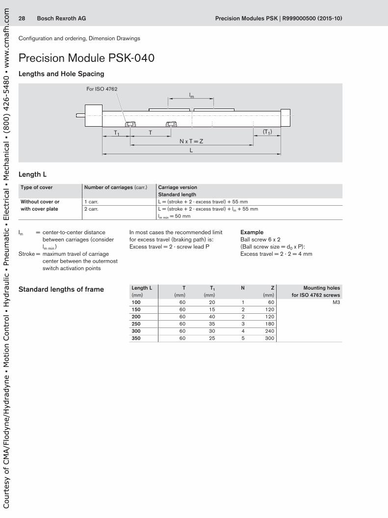
Length L
Im = center-to-center distance between carriages (consider lm min )
Stroke = maximum travel of carriage center between the outermost switch activation points
ExampleBall screw 6 x 2(Ball screw size = d0 x P):Excess travel = 2 · 2 = 4 mm
In most cases the recommended limit for excess travel (braking path) is:Excess travel = 2 · screw lead P
Standard lengths of frame
Type of cover Number of carriages (carr.) Carriage versionStandard length
Without cover or with cover plate
1 carr. L = (stroke + 2 · excess travel) + 55 mm2 carr. L = (stroke + 2 · excess travel) + lm + 55 mm
lm min = 50 mm
Length L(mm)
T(mm)
T1
(mm)N Z
(mm)Mounting holes
for ISO 4762 screws100 60 20 1 60 M3150 60 15 2 120200 60 40 2 120250 60 35 3 180300 60 30 4 240350 60 25 5 300
Precision Module PSK-040Lengths and Hole Spacing
Configuration and ordering, Dimension Drawings
Cou
rtes
y of
CM
A/F
lody
ne/H
ydra
dyne
▪ M
otio
n Con
trol
▪ H
ydra
ulic
▪ P
neum
atic
▪ E
lect
rica
l ▪ M
echa
nica
l ▪ (
800)
426
-548
0 ▪
ww
w.c
maf
h.co
m

29Bosch Rexroth AG
L/2
10 20
47,5
32
20
5
12,524
,5
(T1) 10
19,5
T = 60
19
L
N x 60 = Z
T1
Ø4 h
7
24
18
18
40
18
26,8
Ø3,4 1,6
17,7 20
Ø6
183
A
A
A-A
R999000500 (2015-10) | Precision Modules PSK
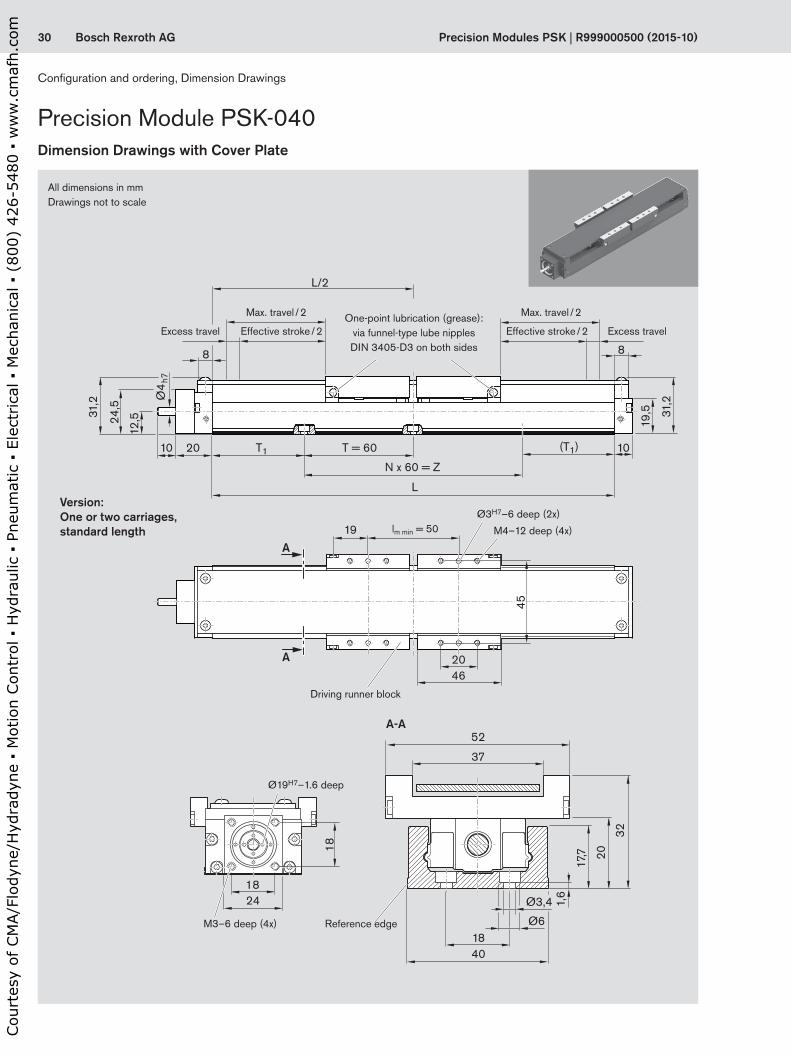
All dimensions in mmDrawings not to scale
Lube holeVersion:One or two carriages, standard length
Ø3H7–5 deep (2x)
M3–4.5 deep (4x)
Excess travel Excess travelEffective stroke / 2
Max. travel / 2
Effective stroke / 2
Max. travel / 2
Reference edgeM3–6 deep (4x)
Driving runner block
lm min = 50
Ø19H7–1.6 deep
Dimension Drawings without Cover
Cou
rtes
y of
CM
A/F
lody
ne/H
ydra
dyne
▪ M
otio
n Con
trol
▪ H
ydra
ulic
▪ P
neum
atic
▪ E
lect
rica
l ▪ M
echa
nica
l ▪ (
800)
426
-548
0 ▪
ww
w.c
maf
h.co
m
30 Bosch Rexroth AG
L/2
8 8
10 20
4620
12,524
,5
31,2
(T1) 10
19,5 31
,2
T = 60
19
L
N x 60 = Z
T1
Ø4
h7
24
18
18
4018
52
37
Ø3,4 1,6
17,7 20
32
Ø6
45
A
A
A-A
Precision Modules PSK | R999000500 (2015-10)
One-point lubrication (grease): via funnel-type lube nipples DIN 3405-D3 on both sides
lm min = 50
All dimensions in mmDrawings not to scale
Version:One or two carriages, standard length
Ø3H7–6 deep (2x)
M4–12 deep (4x)
Excess travel Excess travelEffective stroke / 2
Max. travel / 2
Effective stroke / 2
Max. travel / 2
Driving runner block
Reference edgeM3–6 deep (4x)
Ø19H7–1.6 deep
Precision Module PSK-040Dimension Drawings with Cover Plate
Configuration and ordering, Dimension Drawings
Cou
rtes
y of
CM
A/F
lody
ne/H
ydra
dyne
▪ M
otio
n Con
trol
▪ H
ydra
ulic
▪ P
neum
atic
▪ E
lect
rica
l ▪ M
echa
nica
l ▪ (
800)
426
-548
0 ▪
ww
w.c
maf
h.co
m

31Bosch Rexroth AG
1,6
10
Ø4 h
7
20
Ø19
H7
12,5
Ø4 h
7
Ø19
Ø22
H7
Ø50,818,58
349 43
45
Ø4 h
7
Ø19
Ø22
H7
Ø3,3
Ø43,818,5
83
10
49 43
45
Ø4 h
7
Ø19
Ø22
H7
Ø3,3
Ø36,818,5
83
7
4935
45
D
Lm Lf
R999000500 (2015-10) | Precision Modules PSK
Integrated motor mount (NEMA 17 – Form C) Integrated motor mount (NEMA 17 – Form D)
M3–8 deep
Integrated motor mount (NEMA 14 – Form C)
Dimension Drawings, Motor Attachment
Motor with integrated motor mount and coupling
Motor type Dimensions (mm)D Lf Lm
without brake
with brake
MSM 019A 38 54 72 102MSM 019B 38 54 92 122
Drawings not to scale! For further information and dimensions, see “Motors.”
MF10, MF11
Cable outlet
MF10, MF11 MF10, MF11
MF10, MF11OF01, OF02
Cou
rtes
y of
CM
A/F
lody
ne/H
ydra
dyne
▪ M
otio
n Con
trol
▪ H
ydra
ulic
▪ P
neum
atic
▪ E
lect
rica
l ▪ M
echa
nica
l ▪ (
800)
426
-548
0 ▪
ww
w.c
maf
h.co
m
32 Bosch Rexroth AG Precision Modules PSK | R999000500 (2015-10)
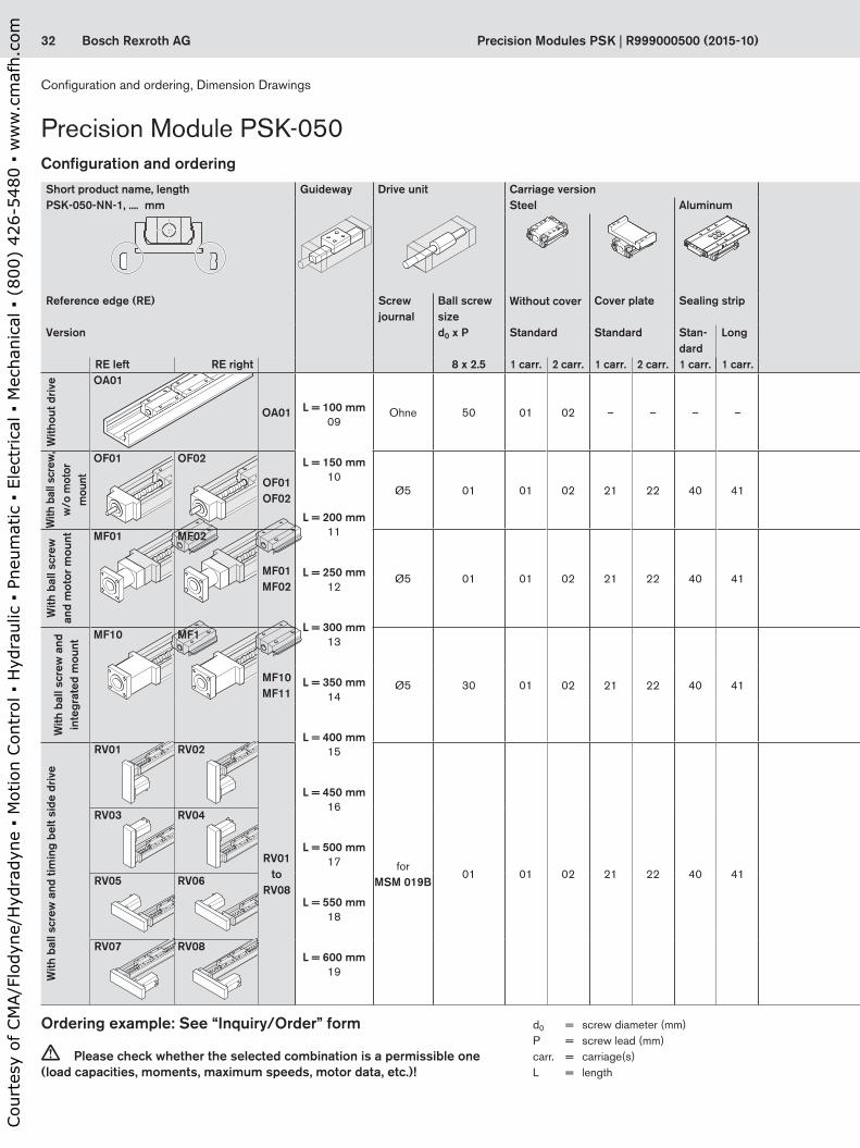
Precision Module PSK-050
RE
RE
RE
RE
RE
RE
Ordering example: See “Inquiry/Order” form
c Please check whether the selected combination is a permissible one (load capacities, moments, maximum speeds, motor data, etc.)!
d0 = screw diameter (mm)P = screw lead (mm) carr. = carriage(s)L = length
Short product name, lengthPSK-050-NN-1, .... mm
Guideway Drive unit Carriage version Motor attachment Motor Type of cover Switches / Mounting duct / Socket-plug
DocumentationSteel Aluminum
Reference edge (RE) Screw journal
Ball screw sized0 x P
Without cover Cover plate Sealing strip Gear ratio i =
Attachment kit 1)
for motor with brake
without brake
with-out
coverplate
strip Standard report
Measure-ment report
Version Standard Standard Stan-dard
Long
RE left RE right 8 x 2.5 1 carr. 2 carr. 1 carr. 2 carr. 1 carr. 1 carr.
With
out d
rive OA01
OA01 L = 100 mm09
L = 150 mm10
L = 200 mm11
L = 250 mm12
L = 300 mm13
L = 350 mm14
L = 400 mm15
L = 450 mm16
L = 500 mm17
L = 550 mm18
L = 600 mm19
Ohne 50 01 02 – – – – — 00 – 00 00 – –
Without switch and Mounting duct
00
Switches:
– Reed sensor– Hall sensor
2122
Mounting duct 26
Switching cam for PSK:– Without cover or
with cover plate– With sealing strip
32
34
01
02Friction mo-
ment
03Lead
deviation
04Travel
accuracy
05Positioning accuracy
With
bal
l scr
ew,
w/o
mot
or
mou
nt
OF01 OF02
OF01OF02
Ø5 01 01 02 21 22 40 41 — 00 – 00
00 01 02
With
bal
l scr
ew
and
mot
or m
ount MF01 MF02
MF01MF02
Ø5 01 01 02 21 22 40 41 —
01 MSM 031B 137 136
03 MSK 030C 85 84
With
bal
l scr
ew a
nd
inte
grat
ed m
ount
MF10 MF1
MF10MF11
Ø5 30 01 02 21 22 40 41 —
31 NEMA 17-D2) 00
35 NEMA 17-C2) 00
36 MSM 019B 135 134
With
bal
l scr
ew a
nd ti
min
g be
lt si
de d
rive
RV01
RV02
RV01to
RV08
for MSM 019B
01 01 02 21 22 40 41
1 13
MSM 019B 135 134
RV03
RV04
RV05
RV06
1,5 14 RV07
RV08
Configuration and ordering
Configuration and ordering, Dimension Drawings
Cou
rtes
y of
CM
A/F
lody
ne/H
ydra
dyne
▪ M
otio
n Con
trol
▪ H
ydra
ulic
▪ P
neum
atic
▪ E
lect
rica
l ▪ M
echa
nica
l ▪ (
800)
426
-548
0 ▪
ww
w.c
maf
h.co
m

33Bosch Rexroth AGR999000500 (2015-10) | Precision Modules PSK
Short product name, lengthPSK-050-NN-1, .... mm
Guideway Drive unit Carriage version Motor attachment Motor Type of cover Switches / Mounting duct / Socket-plug
DocumentationSteel Aluminum
Reference edge (RE) Screw journal
Ball screw sized0 x P
Without cover Cover plate Sealing strip Gear ratio i =
Attachment kit 1)
for motor with brake
without brake
with-out
coverplate
strip Standard report
Measure-ment report
Version Standard Standard Stan-dard
Long
RE left RE right 8 x 2.5 1 carr. 2 carr. 1 carr. 2 carr. 1 carr. 1 carr.
With
out d
rive OA01
OA01 L = 100 mm09
L = 150 mm10
L = 200 mm11
L = 250 mm12
L = 300 mm13
L = 350 mm14
L = 400 mm15
L = 450 mm16
L = 500 mm17
L = 550 mm18
L = 600 mm19
Ohne 50 01 02 – – – – — 00 – 00 00 – –
Without switch and Mounting duct
00
Switches:
– Reed sensor– Hall sensor
2122
Mounting duct 26
Switching cam for PSK:– Without cover or
with cover plate– With sealing strip
32
34
01
02Friction mo-
ment
03Lead
deviation
04Travel
accuracy
05Positioning accuracy
With
bal
l scr
ew,
w/o
mot
or
mou
nt
OF01 OF02
OF01OF02
Ø5 01 01 02 21 22 40 41 — 00 – 00
00 01 02
With
bal
l scr
ew
and
mot
or m
ount MF01 MF02
MF01MF02
Ø5 01 01 02 21 22 40 41 —
01 MSM 031B 137 136
03 MSK 030C 85 84
With
bal
l scr
ew a
nd
inte
grat
ed m
ount
MF10 MF1
MF10MF11
Ø5 30 01 02 21 22 40 41 —
31 NEMA 17-D2) 00
35 NEMA 17-C2) 00
36 MSM 019B 135 134
With
bal
l scr
ew a
nd ti
min
g be
lt si
de d
rive
RV01
RV02
RV01to
RV08
for MSM 019B
01 01 02 21 22 40 41
1 13
MSM 019B 135 134
RV03
RV04
RV05
RV06
1,5 14 RV07
RV08
1) Attachment kit also available without motor (when ordering: enter “00” for motor). For motor mounting kit for customer motor see “Motor mounting” section
Switch mounting arrangementsRefer to “Switch mounting arrange-ments” for more information on switch types and switch mounting.
2) Use motors complying with the appropriate NEMA specification. Because of the varying shaft dimensions for NEMA-specification motors, the attach-ment kit does not include a coupling.
Cou
rtes
y of
CM
A/F
lody
ne/H
ydra
dyne
▪ M
otio
n Con
trol
▪ H
ydra
ulic
▪ P
neum
atic
▪ E
lect
rica
l ▪ M
echa
nica
l ▪ (
800)
426
-548
0 ▪
ww
w.c
maf
h.co
m
34 Bosch Rexroth AG
(T1)
L
N x T = ZT1 T
lm
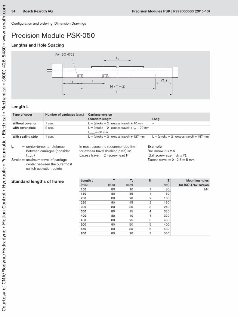
Precision Modules PSK | R999000500 (2015-10)
Precision Module PSK-050
Length L
In most cases the recommended limit for excess travel (braking path) is:Excess travel = 2 · screw lead P
Standard lengths of frame
Type of cover Number of carriages (carr.) Carriage versionStandard length Long
Without cover or with cover plate
1 carr. L = (stroke + 2 · excess travel) + 70 mm –2 carr. L = (stroke + 2 · excess travel) + lm + 70 mm
lm min = 60 mm–
With sealing strip 1 carr. L = (stroke + 2 · excess travel) + 127 mm L = (stroke + 2 · excess travel) + 187 mm
Length L(mm)
T(mm)
T1
(mm)N Z
(mm)Mounting holes
for ISO 4762 screws100 80 10 1 80 M4150 80 35 1 80200 80 20 2 160250 80 45 2 160300 80 30 3 240350 80 15 4 320400 80 40 4 320450 80 25 5 400500 80 50 5 400550 80 35 6 480600 80 20 7 560
Lengths and Hole Spacing
Im = center-to-center distance between carriages (consider lm min )
Stroke = maximum travel of carriage center between the outermost switch activation points
ExampleBall screw 8 x 2.5 (Ball screw size = d0 x P):Excess travel = 2 · 2.5 = 5 mm
For ISO 4762
Configuration and ordering, Dimension Drawings
Cou
rtes
y of
CM
A/F
lody
ne/H
ydra
dyne
▪ M
otio
n Con
trol
▪ H
ydra
ulic
▪ P
neum
atic
▪ E
lect
rica
l ▪ M
echa
nica
l ▪ (
800)
426
-548
0 ▪
ww
w.c
maf
h.co
m

35Bosch Rexroth AG
A
A
L/2
15 30
Ø5 h
7
1631
18,2
58,2
6,5
39,2
30
7,5
(T1) 22
25,5
T = 80
L
N x 80 = Z
T1
25
2,5
3
2,8
B45°
502512
345
Ø4,5 222
,526
Ø8
A-A
B
31,5
23
23
R999000500 (2015-10) | Precision Modules PSK
Lube port for customer-built attachments Ø4H7–5 deep (2x)Funnel-type lube nipple
DIN 3405-D3 M4–6 deep (4x)
For fastening with clamping fixtures
Reference edgeM3–6 deep (4x)
Driving runner block
lm min = 60
Dimension Drawings without Cover
All dimensions in mmDrawings not to scale
Version:One or two carriages
Excess travel Excess travelEffective stroke / 2
Max. travel / 2
Effective stroke / 2
Max. travel / 2
Cou
rtes
y of
CM
A/F
lody
ne/H
ydra
dyne
▪ M
otio
n Con
trol
▪ H
ydra
ulic
▪ P
neum
atic
▪ E
lect
rica
l ▪ M
echa
nica
l ▪ (
800)
426
-548
0 ▪
ww
w.c
maf
h.co
m

36 Bosch Rexroth AG
A-A
A
A
L/2
12 12
15 30
47,4
308
163138
,6
(T1) 22
25,5
T = 80
L
N x 80 = Z
T1
Ø5 h
7
502512
62
47
Ø4,5 222
,5 2640
Ø8
55
2,5
3
2,8
B
B
45°
31,5
23
23
Precision Modules PSK | R999000500 (2015-10)
For fastening with clamping fixtures
Driving runner block
Ø4H7–5 deep (2x)M4–14 deep (4x)
Reference edge
M3–6 deep (4x)
Precision Module PSK-050
lm min = 60
Dimension Drawings with Cover Plate
All dimensions in mmDrawings not to scale
Version:One or two carriages
One-point lubrication (grease): via funnel-type lube nipples DIN 3405-D3
on both sides
Excess travel
Excess travelEffective stroke / 2
Max. travel / 2Effective stroke / 2
Max. travel / 2
Configuration and ordering, Dimension Drawings
Cou
rtes
y of
CM
A/F
lody
ne/H
ydra
dyne
▪ M
otio
n Con
trol
▪ H
ydra
ulic
▪ P
neum
atic
▪ E
lect
rica
l ▪ M
echa
nica
l ▪ (
800)
426
-548
0 ▪
ww
w.c
maf
h.co
m

37Bosch Rexroth AG
15 30 (T1) 22T = 80
L
N x 80 = Z
T1
L/2
12 12
163132
,9
25,5
32,9
258,5 8,5100
4,5
25
6
2525
160
40
40
Ø5 h
7
7
31,5
23
23
502512
49
Ø4,5 228
,940
Ø8
A-A
A
A
2,5
3
2,8
B
B
45°
R999000500 (2015-10) | Precision Modules PSK
Excess travel Excess travelEffective stroke / 2
Max. travel / 2
Effective stroke / 2Max. travel / 2
Version:Carriage, standard length
Version:Carriage, long
Ø4H7–5 deep (2x)
M4–10 deep (4x)
One-point lubrication (grease): via funnel-type lube nipples DIN 3405-D3
on both sides
12.5 for M3
For fastening with clamping fixturesReference edge
M3–5 deep (2x per side)
M4–10 deep (8x)
Ø4H7–5 deep (2x)
M3–6 deep (4x)
Dimension Drawings with Sealing Strip
All dimensions in mmDrawings not to scale
5.5 for M3
12.5 for M35.5 for M3
Cou
rtes
y of
CM
A/F
lody
ne/H
ydra
dyne
▪ M
otio
n Con
trol
▪ H
ydra
ulic
▪ P
neum
atic
▪ E
lect
rica
l ▪ M
echa
nica
l ▪ (
800)
426
-548
0 ▪
ww
w.c
maf
h.co
m

38 Bosch Rexroth AG
2,5
15
Ø5 h
7
Ø25
H7
D
Lm Lf
G
G1
Lm
EK
D
F
L R
X
X
Precision Modules PSK | R999000500 (2015-10)
Precision Module PSK-050Dimension Drawings, Motor Attachment
Motor type Dimensions (mm)D Lf Lm
without brake
with brake
MSM 031B 60,0 53,0 79 115.5MSK 030C 54,0 53,0 188 213.0
Motor with motor mount and coupling
MF01, MF02OF01, OF02
Cable outlet
Version Motor type Dimensions (mm)D E F G G1 K Lm LR
i = 1 i = 1.5without
brakewith
brakeRV01 to RV08 MSM 019B 38 76.5 76.5 48 27.5 29 27.5 92 122 139
Motor with timing belt side drive
View X shown without motor
Left (L)
Right (R)
RV01– RV08
Cable outlet
Configuration and ordering, Dimension Drawings
Cou
rtes
y of
CM
A/F
lody
ne/H
ydra
dyne
▪ M
otio
n Con
trol
▪ H
ydra
ulic
▪ P
neum
atic
▪ E
lect
rica
l ▪ M
echa
nica
l ▪ (
800)
426
-548
0 ▪
ww
w.c
maf
h.co
m
39Bosch Rexroth AG
Ø5 h
7
Ø22
H7
45
Ø3,3
30,5 9
4
5
60 45 Ø43,8
22,5
Ø26
45
5Ø
7h
22Ø
7H
54
30,59
4
6045Ø50,8
5,2254
Ø26
D
Lm Lf
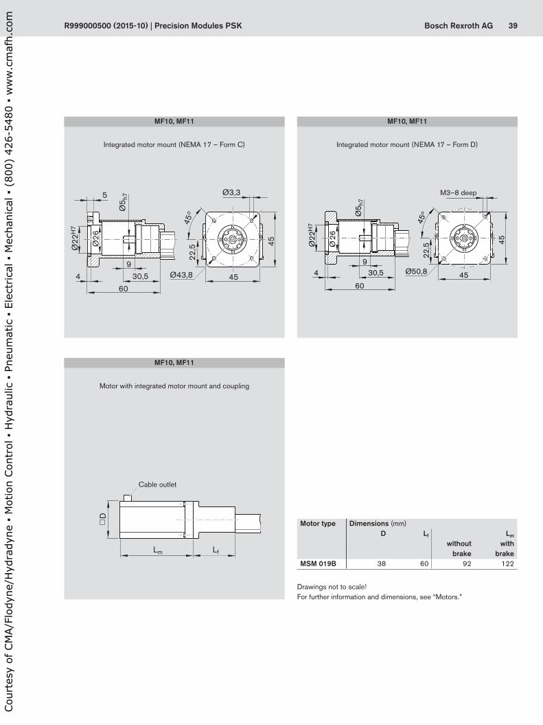
R999000500 (2015-10) | Precision Modules PSK
M3–8 deep
Motor with integrated motor mount and coupling
Integrated motor mount (NEMA 17 – Form D)
Motor type Dimensions (mm)D Lf Lm
without brake
with brake
MSM 019B 38 60 92 122
Drawings not to scale! For further information and dimensions, see “Motors.”
MF10, MF11
MF10, MF11
Cable outlet
Integrated motor mount (NEMA 17 – Form C)
MF10, MF11
Cou
rtes
y of
CM
A/F
lody
ne/H
ydra
dyne
▪ M
otio
n Con
trol
▪ H
ydra
ulic
▪ P
neum
atic
▪ E
lect
rica
l ▪ M
echa
nica
l ▪ (
800)
426
-548
0 ▪
ww
w.c
maf
h.co
m

40 Bosch Rexroth AG Precision Modules PSK | R999000500 (2015-10)
Short product name, lengthPSK-060-NN-1, .... mm
Guideway Drive unit Carriage version Motor attachment Motor Type of cover Switches / Mounting duct / Socket-plug
DocumentationSteel Aluminum
Reference edge (RE) Screw journal
Ball screw sized0 x P
Without cover Cover plate Sealing strip Gear ratio i =
Attach-ment kit 1)
for motor with brake
without brake
with-out
cover plate
strip Standard report
Measure-ment report
Version Stan-dard
Long Stan-dard
Long Stan-dard
Long
RE left RE right 12x2 12x5 12x10 1carr. 2carr. 1carr. 2carr. 1carr. 2carr. 1carr. 2carr. 1carr. 1carr.
With
out
driv
e
OA01
OA01
L = 150 mm10
L = 200 mm11
L = 250 mm12
L = 300 mm13
L = 400 mm15
L = 500 mm17
L = 600 mm19
L = 700 mm21
L = 800 mm23
L = 900 mm25
L = 940 mm26
without 50 01 02 03 04 – – – – – – – 00 – 00 00 – –
Without switch and Mounting duct
00
Switches:
– Reed sensor– Hall sensor
2122
Mounting duct 25
Switching cam for PSK:– Without cover or
with cover plate– With sealing strip
30
31
01
02Friction moment
03Lead
deviation
04Travel
accuracy
05Positioning accuracy
With
bal
l scr
ew,
w/o
mot
or m
ount OF01
OF02
OF01OF02
Ø6 03 01 02 01 02 03 04 21 22 23 24 40 41 – 00 – 00
00 01 02
With
bal
l scr
ew
and
mot
or
mou
nt
MF01
MF02
MF01MF02
Ø6 03 01 02 01 02 03 04 21 22 23 24 40 41 –
03 MSM 031B 137 136
05 MSM 019B 135 134
W/b
all s
crew
and
in
tegr
ated
mou
nt MF10
MF11
MF10MF11
Ø6 30 31 32 01 02 03 04 21 22 23 24 40 41 –
31 NEMA 23-D2) 00
34 NEMA 23-C2) 00
32 MSK 030C 85 84
With
bal
l scr
ew a
nd ti
min
g be
lt si
de d
rive
RV01
RV02
RV01to
RV08
for MSK 030C MSM 031B MSM 019B
03 01 02 01 02 03 04 21 22 23 24 40 41
i = 1
11 MSK 030C 85 84
RV03
RV04
13 MSM 031B 137 136
17 MSM 019B 135 134
RV05
RV06
i = 1,5
12 MSK 030C 85 84
RV07
RV08
14 MSM 031B 137 136
18 MSM 019B 135 134
Precision Module PSK-060
RE
RE
RE
RE
RE
RE
RE
RE
RE
RE
RE
RE
RE
RE
Ordering example: See “Inquiry/Order” form d0 = screw diameter (mm)P = screw lead (mm) carr. = carriage(s)L = length
Configuration and ordering
Configuration and ordering, Dimension Drawings
Cou
rtes
y of
CM
A/F
lody
ne/H
ydra
dyne
▪ M
otio
n Con
trol
▪ H
ydra
ulic
▪ P
neum
atic
▪ E
lect
rica
l ▪ M
echa
nica
l ▪ (
800)
426
-548
0 ▪
ww
w.c
maf
h.co
m

41Bosch Rexroth AGR999000500 (2015-10) | Precision Modules PSK
Short product name, lengthPSK-060-NN-1, .... mm
Guideway Drive unit Carriage version Motor attachment Motor Type of cover Switches / Mounting duct / Socket-plug
DocumentationSteel Aluminum
Reference edge (RE) Screw journal
Ball screw sized0 x P
Without cover Cover plate Sealing strip Gear ratio i =
Attach-ment kit 1)
for motor with brake
without brake
with-out
cover plate
strip Standard report
Measure-ment report
Version Stan-dard
Long Stan-dard
Long Stan-dard
Long
RE left RE right 12x2 12x5 12x10 1carr. 2carr. 1carr. 2carr. 1carr. 2carr. 1carr. 2carr. 1carr. 1carr.
With
out
driv
e
OA01
OA01
L = 150 mm10
L = 200 mm11
L = 250 mm12
L = 300 mm13
L = 400 mm15
L = 500 mm17
L = 600 mm19
L = 700 mm21
L = 800 mm23
L = 900 mm25
L = 940 mm26
without 50 01 02 03 04 – – – – – – – 00 – 00 00 – –
Without switch and Mounting duct
00
Switches:
– Reed sensor– Hall sensor
2122
Mounting duct 25
Switching cam for PSK:– Without cover or
with cover plate– With sealing strip
30
31
01
02Friction moment
03Lead
deviation
04Travel
accuracy
05Positioning accuracy
With
bal
l scr
ew,
w/o
mot
or m
ount OF01
OF02
OF01OF02
Ø6 03 01 02 01 02 03 04 21 22 23 24 40 41 – 00 – 00
00 01 02
With
bal
l scr
ew
and
mot
or
mou
nt
MF01
MF02
MF01MF02
Ø6 03 01 02 01 02 03 04 21 22 23 24 40 41 –
03 MSM 031B 137 136
05 MSM 019B 135 134
W/b
all s
crew
and
in
tegr
ated
mou
nt MF10
MF11
MF10MF11
Ø6 30 31 32 01 02 03 04 21 22 23 24 40 41 –
31 NEMA 23-D2) 00
34 NEMA 23-C2) 00
32 MSK 030C 85 84
With
bal
l scr
ew a
nd ti
min
g be
lt si
de d
rive
RV01
RV02
RV01to
RV08
for MSK 030C MSM 031B MSM 019B
03 01 02 01 02 03 04 21 22 23 24 40 41
i = 1
11 MSK 030C 85 84
RV03
RV04
13 MSM 031B 137 136
17 MSM 019B 135 134
RV05
RV06
i = 1,5
12 MSK 030C 85 84
RV07
RV08
14 MSM 031B 137 136
18 MSM 019B 135 134
1) Attachment kit also available without motor (when ordering: enter “00” for motor). For motor mounting kit for customer motor see “Motor mounting” section.
Switch mounting arrangementsRefer to “Switch mounting arrange-ments” for more information on switch types and switch mounting.
2) Use motors complying with the appropriate NEMA specification. Because of the varying shaft dimensions for NEMA-specification motors, the attach-ment kit does not include a coupling.
Cou
rtes
y of
CM
A/F
lody
ne/H
ydra
dyne
▪ M
otio
n Con
trol
▪ H
ydra
ulic
▪ P
neum
atic
▪ E
lect
rica
l ▪ M
echa
nica
l ▪ (
800)
426
-548
0 ▪
ww
w.c
maf
h.co
m

42 Bosch Rexroth AG
(T1)
L
N x T = ZT1 T
lm
Precision Modules PSK | R999000500 (2015-10)
Standard lengths of frame
Length L
Precision Module PSK-060
Type of cover Number of carriages (carr.) Carriage versionStandard length Long
Without cover or with cover plate
1 carr. L = (stroke + 2 · excess travel) + 70 mm L = (stroke + 2 · excess travel) + 85 mm2 carr. L = (stroke + 2 · excess travel) + lm + 70 mm
lm min = 60 mmL = (stroke + 2 · excess travel) + lm + 85 mmlm min = 75 mm
With sealing strip 1 carr. L = (stroke + 2 · excess travel) + 160 mm L = (stroke + 2 · excess travel) + 215 mm
Length L(mm)
T(mm)
T1
(mm)N Z
(mm)Mounting holes
for ISO 4762 screws150 100 25 1 100 M5200 100 50 1 100250 100 25 2 200300 100 50 2 200400 100 50 3 300500 100 50 4 400600 100 50 5 500700 100 50 6 600800 100 50 7 700900 100 50 8 800940 100 20 9 900
Lengths and Hole Spacing
Im = center-to-center distance between carriages (consider lm min )
Stroke = maximum travel of carriage center between the outermost switch activation points
In most cases the recommended limit for excess travel (braking path) is:Excess travel = 2 · screw lead P
ExampleBall screw 12 x 10 (Ball screw size = d0 x P):Excess travel = 2 · 10 = 20 mm
For ISO 4762
Configuration and ordering, Dimension Drawings
Cou
rtes
y of
CM
A/F
lody
ne/H
ydra
dyne
▪ M
otio
n Con
trol
▪ H
ydra
ulic
▪ P
neum
atic
▪ E
lect
rica
l ▪ M
echa
nica
l ▪ (
800)
426
-548
0 ▪
ww
w.c
maf
h.co
m

43Bosch Rexroth AG
A-A
A
A
6030
1039,4
Ø 5,5
2,8
29,7 33
Ø1018
L/2
18 30
2135,9
(T1)T1 25
31,9
100
16
L
58,239,2
9
72,653,6
22
30
30
9
N x 100 = Z
Ø6 h
7
9
30
2,5
4,5
2,8
B
B
45°
23
4033
R999000500 (2015-10) | Precision Modules PSK
Version:One or two carriages, standard length
Ø5H7–8 deep (2x)
Excess travel
Excess travelEffective stroke / 2
Max. travel / 2
Effective stroke / 2
Max. travel / 2
M5–8 deep (2x)
Lube port for customer-built attachments
Funnel-type lube nippleDIN 3405-D3
Ø5H7–8 deep (2x)M5–8 deep (4x)
Version:One or two carriages, long
M4–8 deep (4x)
Dimension Drawings without Cover
All dimensions in mmDrawings not to scale
lm min = 60
Driving runner block
Funnel-type lube nipple DIN 3405-D3
lm min = 75
For fastening with clamping fixtures
Reference edge
Cou
rtes
y of
CM
A/F
lody
ne/H
ydra
dyne
▪ M
otio
n Con
trol
▪ H
ydra
ulic
▪ P
neum
atic
▪ E
lect
rica
l ▪ M
echa
nica
l ▪ (
800)
426
-548
0 ▪
ww
w.c
maf
h.co
m

44 Bosch Rexroth AG
A-A
A
A
L/2
18
9 9
30
35,9
21
47,3
(T1) 25
31,9 47
,3
100
L
40916
553022,5
74
N x 100 = ZT1
Ø6 h
7
6030
6286
Ø5,5
2,8
29,7 33
48
Ø1018
40
23
33
74
2,5
4,5
2,8
B
B
45°
Precision Modules PSK | R999000500 (2015-10)
Excess travel Excess travelEffective stroke / 2Max. travel / 2
Effective stroke / 2Max. travel / 2
Version:One or two carriages, standard length
Version:One or two carriages, long
Ø5H7–8 deep (2x)M5–15 deep (2x)
Ø5H7–8 deep (2x)
M5–15 deep (4x)
M4–8 deep (4x)
Dimension Drawings with Cover Plate
All dimensions in mmDrawings not to scale
One-point lubrication (grease): via funnel-type lube nipples DIN 3405-D3
on both sides
For fastening with clamping fixtures
Reference edge
lm min = 60
lm min = 75Driving runner block
Precision Module PSK-060
Configuration and ordering, Dimension Drawings
Cou
rtes
y of
CM
A/F
lody
ne/H
ydra
dyne
▪ M
otio
n Con
trol
▪ H
ydra
ulic
▪ P
neum
atic
▪ E
lect
rica
l ▪ M
echa
nica
l ▪ (
800)
426
-548
0 ▪
ww
w.c
maf
h.co
m

45Bosch Rexroth AG
A-A
A
A
L/2
18
9 9
8,58,5
30
35,9
21
40
(T1) 25
31,9 40
100
L
9
45130
5,5
30 30 30186
50
249
N x 100 = ZT1
Ø6 h
7 5,6
50
3858,5
48
6030
Ø5,5
2,8
36,1
Ø1018
23
4033
2,5
4,5
2,8
B
B
45°
R999000500 (2015-10) | Precision Modules PSK
Excess travel Excess travelEffective stroke / 2Max. travel / 2
Effective stroke / 2Max. travel / 2
Version:Carriage, standard length
Version:Carriage, long
Ø5H7–8 deep (2x) M5–10 deep (4x)
M5–10 deep (8x)Ø5H7–8 deep (2x)
M4–8 deep (4x)
12 for M3
M3–7 deep (2x per side)
12 for M3
Dimension Drawings with Sealing Strip
One-point lubrication (grease): via funnel-type lube nipples DIN 3405-D3
on both sides
All dimensions in mmDrawings not to scale
For fastening with clamping fixtures
Reference edge
Cou
rtes
y of
CM
A/F
lody
ne/H
ydra
dyne
▪ M
otio
n Con
trol
▪ H
ydra
ulic
▪ P
neum
atic
▪ E
lect
rica
l ▪ M
echa
nica
l ▪ (
800)
426
-548
0 ▪
ww
w.c
maf
h.co
m

46 Bosch Rexroth AG
2,5
18
Ø6 h
7
Ø28
H7
6Ø
7h
1,83Ø
7H
5,03
82Ø 59
4 349
59 59
Ø66,68
54
6Ø
7h
1,83Ø
7H
5,03
82Ø
4 349
59 59
59
Ø66,68
Ø4,78
54
D
Lm Lf
D
Lm Lf
Precision Modules PSK | R999000500 (2015-10)
Precision Module PSK-060Dimension Drawings, Motor Attachment
M4–10 deep
Motor with motor mount and coupling
MF01, MF02OF01, OF02
Motor with integrated motor mount and coupling
Integrated motor mount (NEMA 23 – Form C)
Motor type Dimensions (mm)D Lf Lm
without brake
with brake
MSK 030C 54 59 188 213
Drawings not to scale! For further information and dimensions, see “Motors.”
Motor type Dimensions (mm)D Lf Lm
without brake
with brake
MSM 019B 38 45 92 122.0MSK 030C 54 50 188 213.0MSM 031B 60 50 79 115.5
MF10, MF11
MF10, MF11
Cable outlet
Cable outletIntegrated motor mount (NEMA 23 – Form D)
MF10, MF11
Configuration and ordering, Dimension Drawings
Cou
rtes
y of
CM
A/F
lody
ne/H
ydra
dyne
▪ M
otio
n Con
trol
▪ H
ydra
ulic
▪ P
neum
atic
▪ E
lect
rica
l ▪ M
echa
nica
l ▪ (
800)
426
-548
0 ▪
ww
w.c
maf
h.co
m
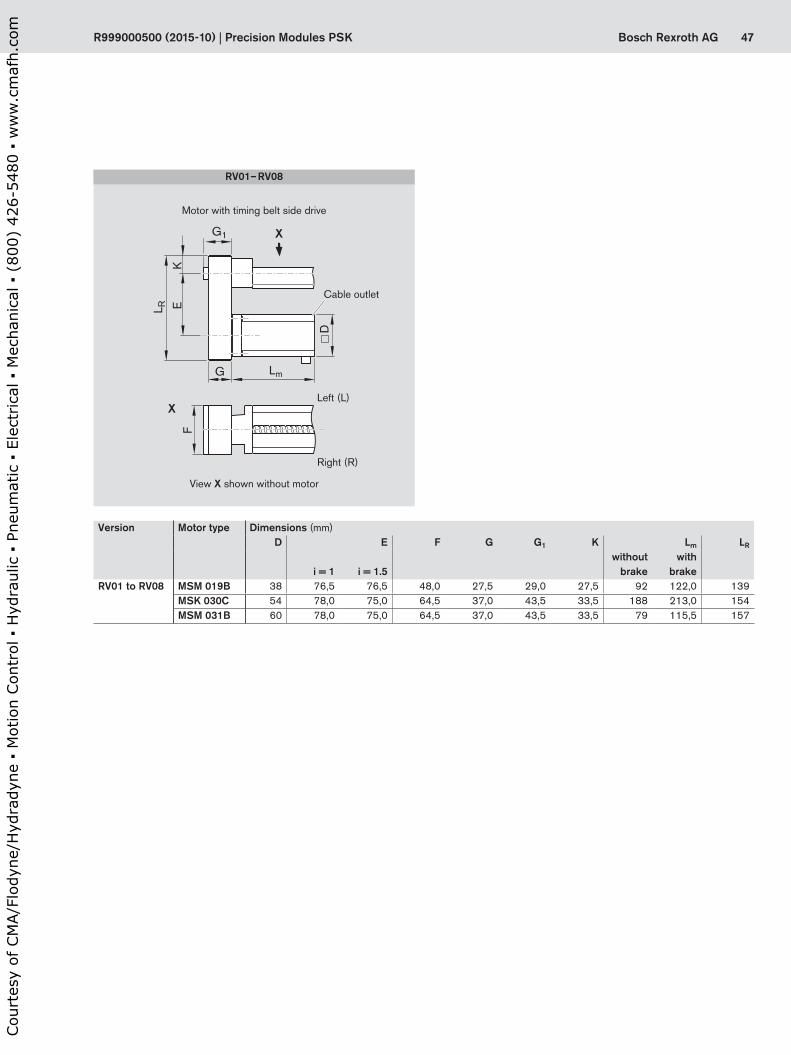
47Bosch Rexroth AG
G
G1
Lm
EK
D
F
L R
X
X
R999000500 (2015-10) | Precision Modules PSK
Motor with timing belt side drive
View X shown without motor
Left (L)
Right (R)
RV01– RV08
Cable outlet
Version Motor type Dimensions (mm)D E F G G1 K Lm LR
i = 1 i = 1.5without
brakewith
brakeRV01 to RV08 MSM 019B 38 76,5 76,5 48,0 27,5 29,0 27,5 92 122,0 139
MSK 030C 54 78,0 75,0 64,5 37,0 43,5 33,5 188 213,0 154MSM 031B 60 78,0 75,0 64,5 37,0 43,5 33,5 79 115,5 157
Cou
rtes
y of
CM
A/F
lody
ne/H
ydra
dyne
▪ M
otio
n Con
trol
▪ H
ydra
ulic
▪ P
neum
atic
▪ E
lect
rica
l ▪ M
echa
nica
l ▪ (
800)
426
-548
0 ▪
ww
w.c
maf
h.co
m
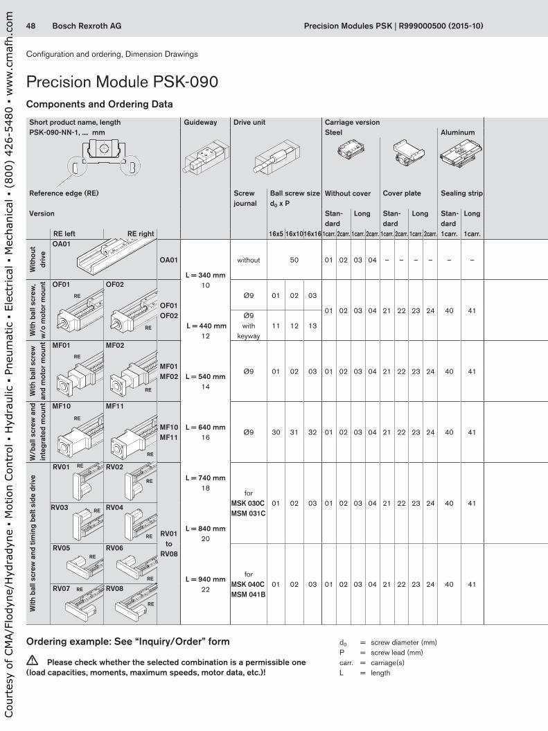
48 Bosch Rexroth AG Precision Modules PSK | R999000500 (2015-10)
Precision Module PSK-090Components and Ordering Data
Short product name, lengthPSK-090-NN-1, .... mm
Guideway Drive unit Carriage version Motor attachment Motor Type of cover Switches / Mounting duct / Socket-plug
DocumentationSteel Aluminum
Reference edge (RE) Screw journal
Ball screw sized0 x P
Without cover Cover plate Sealing strip Gear ratio i =
Attach-ment kit 1)
for motor with brake
without brake
with-out
cover plate
strip Standard report
Measure-ment report
Version Stan-dard
Long Stan-dard
Long Stan-dard
Long
RE left RE right 16x5 16x1016x16 1carr. 2carr. 1carr. 2carr. 1carr. 2carr. 1carr. 2carr. 1carr. 1carr.
With
out
driv
e
OA01
OA01
L = 340 mm10
L = 440 mm12
L = 540 mm14
L = 640 mm16
L = 740 mm18
L = 840 mm20
L = 940 mm22
without 50 01 02 03 04 – – – – – – – 00 – 00 00 – –
Without switch and Mounting duct
00
Switches:
– Reed sensor– Hall sensor
2122
Mounting duct 25
Switching cam for PSK:– Without cover or
with cover plate– With sealing strip
30
31
01
02Friction moment
03Lead
deviation
04Travel
accuracy
05Positioning accuracy
With
bal
l scr
ew,
w/o
mot
or m
ount OF01
OF02
OF01OF02
Ø9 01 02 03
01 02 03 04 21 22 23 24 40 41 – 00 – 00
00 01 02
Ø9with
keyway11 12 13
With
bal
l scr
ew
and
mot
or m
ount MF01
MF02
MF01MF02
Ø9 01 02 03 01 02 03 04 21 22 23 24 40 41 –
03 MSK 040C 87 86
06 MSM 041B 141 140
W/b
all s
crew
and
in
tegr
ated
mou
nt MF10
MF11
MF10MF11
Ø9 30 31 32 01 02 03 04 21 22 23 24 40 41 –
31 NEMA 23-D2) 00
32 MSK 030C 85 84
33 MSM 031C 139 138
With
bal
l scr
ew a
nd ti
min
g be
lt si
de d
rive
RV01
RV02
RV01to
RV08
forMSK 030CMSM 031C
01 02 03 01 02 03 04 21 22 23 24 40 41
i = 1 40MSK 030C 85 84
i = 1,5 41
i = 1 42MSM 031C 139 138
i = 1,5 43
RV03
RV04
RV05
RV06
forMSK 040CMSM 041B
01 02 03 01 02 03 04 21 22 23 24 40 41
i = 1 44MSK 040C 87 86
i = 1,5 45
i = 1 46MSM 041B 141 140
i = 1,5 47
RV07
RV08
RE
RE
RE
RE
RE
RE
RE
RE
RE
RE
RE
RE
RE
RE
Ordering example: See “Inquiry/Order” form
c Please check whether the selected combination is a permissible one (load capacities, moments, maximum speeds, motor data, etc.)!
d0 = screw diameter (mm)P = screw lead (mm) carr. = carriage(s)L = length
Configuration and ordering, Dimension Drawings
Cou
rtes
y of
CM
A/F
lody
ne/H
ydra
dyne
▪ M
otio
n Con
trol
▪ H
ydra
ulic
▪ P
neum
atic
▪ E
lect
rica
l ▪ M
echa
nica
l ▪ (
800)
426
-548
0 ▪
ww
w.c
maf
h.co
m

49Bosch Rexroth AGR999000500 (2015-10) | Precision Modules PSK
Short product name, lengthPSK-090-NN-1, .... mm
Guideway Drive unit Carriage version Motor attachment Motor Type of cover Switches / Mounting duct / Socket-plug
DocumentationSteel Aluminum
Reference edge (RE) Screw journal
Ball screw sized0 x P
Without cover Cover plate Sealing strip Gear ratio i =
Attach-ment kit 1)
for motor with brake
without brake
with-out
cover plate
strip Standard report
Measure-ment report
Version Stan-dard
Long Stan-dard
Long Stan-dard
Long
RE left RE right 16x5 16x1016x16 1carr. 2carr. 1carr. 2carr. 1carr. 2carr. 1carr. 2carr. 1carr. 1carr.
With
out
driv
e
OA01
OA01
L = 340 mm10
L = 440 mm12
L = 540 mm14
L = 640 mm16
L = 740 mm18
L = 840 mm20
L = 940 mm22
without 50 01 02 03 04 – – – – – – – 00 – 00 00 – –
Without switch and Mounting duct
00
Switches:
– Reed sensor– Hall sensor
2122
Mounting duct 25
Switching cam for PSK:– Without cover or
with cover plate– With sealing strip
30
31
01
02Friction moment
03Lead
deviation
04Travel
accuracy
05Positioning accuracy
With
bal
l scr
ew,
w/o
mot
or m
ount OF01
OF02
OF01OF02
Ø9 01 02 03
01 02 03 04 21 22 23 24 40 41 – 00 – 00
00 01 02
Ø9with
keyway11 12 13
With
bal
l scr
ew
and
mot
or m
ount MF01
MF02
MF01MF02
Ø9 01 02 03 01 02 03 04 21 22 23 24 40 41 –
03 MSK 040C 87 86
06 MSM 041B 141 140
W/b
all s
crew
and
in
tegr
ated
mou
nt MF10
MF11
MF10MF11
Ø9 30 31 32 01 02 03 04 21 22 23 24 40 41 –
31 NEMA 23-D2) 00
32 MSK 030C 85 84
33 MSM 031C 139 138
With
bal
l scr
ew a
nd ti
min
g be
lt si
de d
rive
RV01
RV02
RV01to
RV08
forMSK 030CMSM 031C
01 02 03 01 02 03 04 21 22 23 24 40 41
i = 1 40MSK 030C 85 84
i = 1,5 41
i = 1 42MSM 031C 139 138
i = 1,5 43
RV03
RV04
RV05
RV06
forMSK 040CMSM 041B
01 02 03 01 02 03 04 21 22 23 24 40 41
i = 1 44MSK 040C 87 86
i = 1,5 45
i = 1 46MSM 041B 141 140
i = 1,5 47
RV07
RV08
1) Attachment kit also available without motor (when ordering: enter “00” for motor). For motor mounting kit for customer motor see “Motor mounting” section.
Switch mounting arrangementsRefer to “Switch mounting arrange-ments” for more information on switch types and switch mounting.
2) Use motors complying with the appropriate NEMA specification. Because of the varying shaft dimensions for NEMA-specification motors, the attach-ment kit does not include a coupling.
Cou
rtes
y of
CM
A/F
lody
ne/H
ydra
dyne
▪ M
otio
n Con
trol
▪ H
ydra
ulic
▪ P
neum
atic
▪ E
lect
rica
l ▪ M
echa
nica
l ▪ (
800)
426
-548
0 ▪
ww
w.c
maf
h.co
m

50 Bosch Rexroth AG
(T1)
L
N x T = ZT1 T
lm
Precision Modules PSK | R999000500 (2015-10)
Precision Module PSK-090
Standard lengths of frame
Length L
Type of cover Number of carriages (carr.)
Carriage versionStandard length Long
Without cover or with cover plate
1 carr. L = (stroke + 2 · excess travel) + 100 mm L = (stroke + 2 · excess travel) + 120 mm2 carr. L = (stroke + 2 · excess travel) + lm + 100 mm
lm min = 90 mmL = (stroke + 2 · excess travel) + lm + 120 mmlm min = 110 mm
With sealing strip 1 carr. L = (stroke + 2 · excess travel) + 190 mm L = (stroke + 2 · excess travel) + 265 mm
Lengths and Hole Spacing
Im = center-to-center distance between carriages (consider lm min )
Stroke = maximum travel of carriage center between the outermost switch activation points
In most cases the recommended limit for excess travel (braking path) is:Excess travel = 2 · screw lead P
ExampleBall screw 16 x 10 (Ball screw size = d0 x P):Excess travel = 2 · 10 = 20 mm
For ISO 4762
Length L(mm)
T(mm)
T1
(mm)N Z
(mm)Mounting holes
for ISO 4762 screws340 100 70 2 200 M6440 100 70 3 300540 100 70 4 400640 100 70 5 500740 100 70 6 600840 100 70 7 700940 100 70 8 800
Configuration and ordering, Dimension Drawings
Cou
rtes
y of
CM
A/F
lody
ne/H
ydra
dyne
▪ M
otio
n Con
trol
▪ H
ydra
ulic
▪ P
neum
atic
▪ E
lect
rica
l ▪ M
echa
nica
l ▪ (
800)
426
-548
0 ▪
ww
w.c
maf
h.co
m
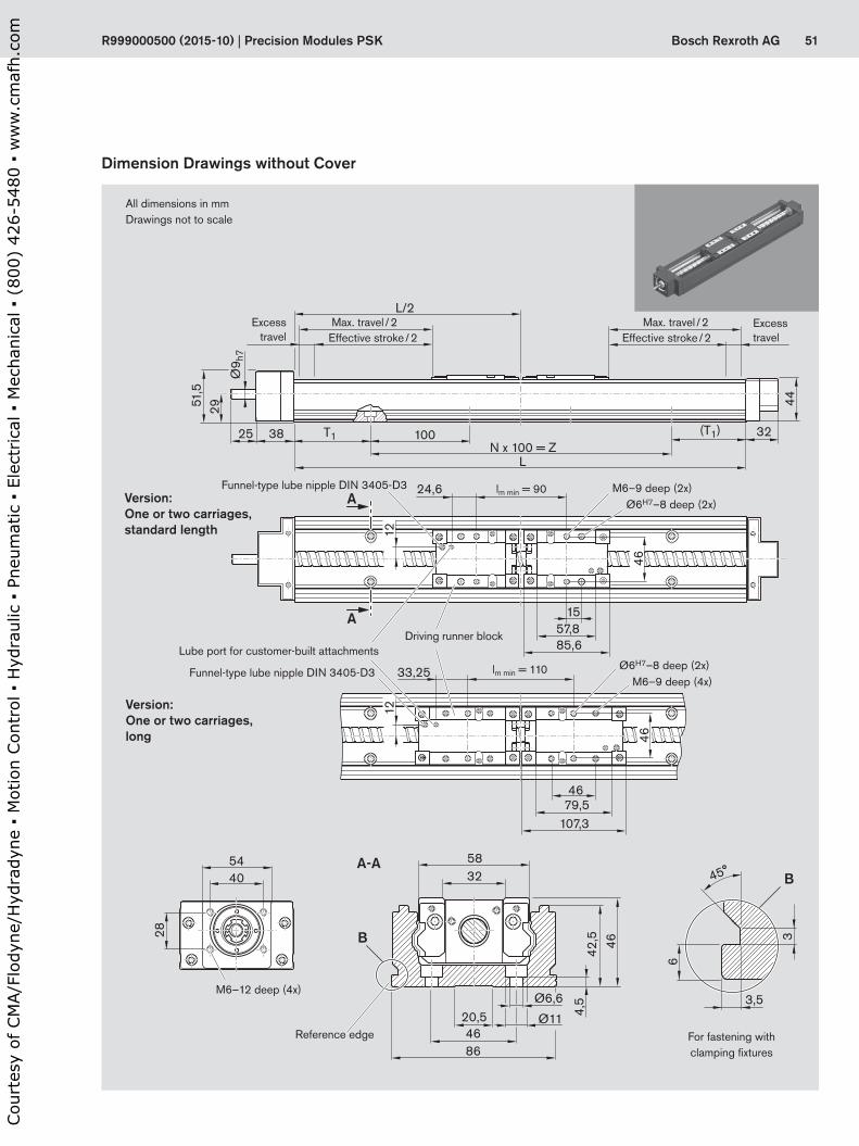
51Bosch Rexroth AG
A-A
A
A
L/2
25 38
2951,5
(T1) 32
44
100
L
85,6
24,6
57,815
107,379,5
33,25
46
N x 100 = ZT1
Ø9 h
7
4646
8646
3258
Ø6,6
4,5
42,5 46
Ø1120,5
54
28
40
1212
3
6
3,5
B
B
45°
R999000500 (2015-10) | Precision Modules PSK
Version:One or two carriages, standard length
Ø6H7–8 deep (2x)
Excess travel
Excess travelEffective stroke / 2
Max. travel / 2Effective stroke / 2
Max. travel / 2
M6–9 deep (2x)
Ø6H7–8 deep (2x)M6–9 deep (4x)
Version:One or two carriages, long
M6–12 deep (4x)
Dimension Drawings without Cover
All dimensions in mmDrawings not to scale
For fastening with clamping fixtures
Reference edge
Lube port for customer-built attachments
Funnel-type lube nipple DIN 3405-D3
Driving runner block
Funnel-type lube nipple DIN 3405-D3 lm min = 90
lm min = 110
Cou
rtes
y of
CM
A/F
lody
ne/H
ydra
dyne
▪ M
otio
n Con
trol
▪ H
ydra
ulic
▪ P
neum
atic
▪ E
lect
rica
l ▪ M
echa
nica
l ▪ (
800)
426
-548
0 ▪
ww
w.c
maf
h.co
m
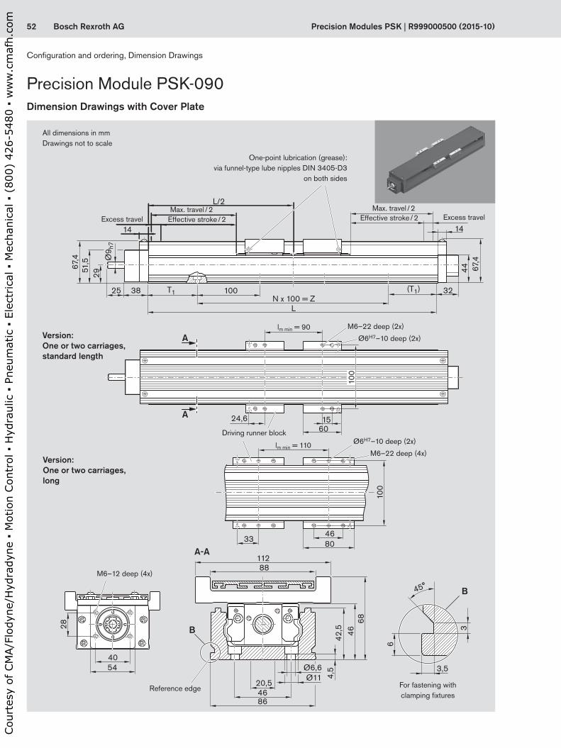
52 Bosch Rexroth AG
A-A
A
A
88112
68
L/2
14
25 38
2951
,567,4
24,6
3346
100
100
80
1560
14
(T1) 32
44 67,4
100
LN x 100 = Z
T1
8646
Ø6,6
4,5
42,5 46
Ø1120,5
3
6
3,554
28
40
B
B
Ø9 h
7
45°
Precision Modules PSK | R999000500 (2015-10)
Precision Module PSK-090Dimension Drawings with Cover Plate
Excess travel Excess travelEffective stroke / 2Max. travel / 2
Effective stroke / 2Max. travel / 2
Version:One or two carriages, standard length
Version:One or two carriages, long
Driving runner block
Ø6H7–10 deep (2x)
M6–22 deep (2x)
Ø6H7–10 deep (2x)
M6–22 deep (4x)
M6–12 deep (4x)
All dimensions in mmDrawings not to scale
One-point lubrication (grease): via funnel-type lube nipples DIN 3405-D3
on both sides
For fastening with clamping fixtures
Reference edge
lm min = 90
lm min = 110
Configuration and ordering, Dimension Drawings
Cou
rtes
y of
CM
A/F
lody
ne/H
ydra
dyne
▪ M
otio
n Con
trol
▪ H
ydra
ulic
▪ P
neum
atic
▪ E
lect
rica
l ▪ M
echa
nica
l ▪ (
800)
426
-548
0 ▪
ww
w.c
maf
h.co
m

53Bosch Rexroth AG
A-A
A
A
L/2
14
25 38
2951
,556
,5
10,5 10,5
23
23040
834
40 40
14
(T1) 32
44 56,7
100
L
15560
N x 100 = ZT1
Ø9 h
7
11
65
65
54
28
40
4884
68
8646
Ø6,6
4,5
51,7
Ø1120,5
3
6
3,5
B
B
45°
R999000500 (2015-10) | Precision Modules PSK
Excess travel Excess travelEffective stroke / 2Max. travel / 2
Effective stroke / 2Max. travel / 2
Version:Carriage, standard length
Version:Carriage, long
Ø6H7–10 deep (2x) M6–15 deep (4x)
M6–15 deep (8x)Ø6H7–10 deep (2x)
12 for M3
M6–12 deep (4x)
M3–7 deep (2x per side)
Dimension Drawings with Sealing Strip
One-point lubrication (grease): via funnel-type lube nipples DIN 3405-D3
on both sides
All dimensions in mmDrawings not to scale
For fastening with clamping fixtures
Reference edge
12 for M3
Cou
rtes
y of
CM
A/F
lody
ne/H
ydra
dyne
▪ M
otio
n Con
trol
▪ H
ydra
ulic
▪ P
neum
atic
▪ E
lect
rica
l ▪ M
echa
nica
l ▪ (
800)
426
-548
0 ▪
ww
w.c
maf
h.co
m

54 Bosch Rexroth AG
2,5
25
Ø9 h
7
Ø40
H7
2,5
h = 1,8
3P9
20
Ø9 h
7
Ø38
,1H
7
4 5117,5
87,5
30
60
60Ø66,68
45°
D
Lm Lf
D
Lm Lf
Precision Modules PSK | R999000500 (2015-10)
Precision Module PSK-090Dimension Drawings, Motor Attachment
Motor with motor mount and coupling
M4–9 deep
Motor with integrated motor mount and couplingIntegrated motor mount (NEMA 23 – Form D)
Motor type Dimensions (mm)D Lf Lm
without brake
with brake
MSM 031C 60 87.5 98.5 135.0MSK 030C 54 87.5 188.0 213.0
Drawings not to scale! For further information and dimensions, see “Motors.”
Motor type Dimensions (mm)D Lf Lm
without brake
with brake
MSM 031C 60.0 72.0 98.5 135.0MSM 041B 80.0 81.0 112.0 149.0MSK 030C 54.0 75.0 188.0 213.0MSK 040C 82.0 77.5 185.5 215.5
MF01, MF02OF01, OF02
MF10, MF11MF10, MF11
Cable outlet
Cable outlet
Configuration and ordering, Dimension Drawings
Cou
rtes
y of
CM
A/F
lody
ne/H
ydra
dyne
▪ M
otio
n Con
trol
▪ H
ydra
ulic
▪ P
neum
atic
▪ E
lect
rica
l ▪ M
echa
nica
l ▪ (
800)
426
-548
0 ▪
ww
w.c
maf
h.co
m

55Bosch Rexroth AG
G
G1
Lm
EK
D
F
L R
X
X
R999000500 (2015-10) | Precision Modules PSK
Version Motor type Dimensions (mm)D E F G G1 K Lm LR
i = 1 i = 1.5without
brakewith
brake i = 1 i = 1.5RV01 to RV08 MSM 031C 60 103.5 115.0 64.5 37 43.5 33.5 98.5 135.0 180.0 191.5
MSM 041B 80 122.0 122.0 88.0 51 57.0 45.5 112.0 149.0 231.0 231.0MSK 030C 54 103.5 115.0 64.5 37 43.5 33.5 188.0 213.0 180.0 191.5MSK 040C 80 122.0 122.0 88.0 51 57.0 45.5 185.5 215.5 231.0 231.0
Motor with timing belt side drive
View X shown without motor
Left (L)
Right (R)
RV01– RV08
Cable outlet
Cou
rtes
y of
CM
A/F
lody
ne/H
ydra
dyne
▪ M
otio
n Con
trol
▪ H
ydra
ulic
▪ P
neum
atic
▪ E
lect
rica
l ▪ M
echa
nica
l ▪ (
800)
426
-548
0 ▪
ww
w.c
maf
h.co
m

56 Bosch Rexroth AG
1
2
3
3
1
2
4
Precision Modules PSK | R999000500 (2015-12)
Switch Mounting Arrangements
Ordering the switches and accessoriesRefer to the following table for part numbers.Accessories can also be ordered separately.
Item Part numbersPSK-040 PSK-050 PSK-060 and PSK-090
1 Switches– Reed sensor R3476 018 03 R3476 018 03 R3476 018 03– Hall sensor R3476 019 03 R3476 019 03 R3476 019 03
2 Mounting duct R0399 800 97 R0396 620 20 R0396 620 193 Switching cam
– For PSK without cover or with cover plate
R1419 000 12 R1419 000 10 R1419 000 04
– For PSK with sealing strip – R1419 000 11 R1419 000 05
Left (L)
Right (R)
Overview of switching system
1 Switch2 Switching cam3 Mounting duct (aluminum alloy, black
anodized)4 Socket head cap screw with washer
Notes for mountingA mounting duct is required for installa-tion of the switches.
c Short stroke: Consider the length of the switch!
Mounting side:Switches may be mounted on the left (L) or right (R) side of the module.
For two-carriage versions:Switch actuation by the driving runner block (on the motor side).
The switching system (switch, switching cam, mounting duct, standard parts) is supplied loose.
Switching system
PSK-050 to 90
PSK-040
Length calculation mounting duct : PSK40: L + 15 mm PSK-050 to PSK-090: L – 2 mm
Attachments and Accessories
Cou
rtes
y of
CM
A/F
lody
ne/H
ydra
dyne
▪ M
otio
n Con
trol
▪ H
ydra
ulic
▪ P
neum
atic
▪ E
lect
rica
l ▪ M
echa
nica
l ▪ (
800)
426
-548
0 ▪
ww
w.c
maf
h.co
m
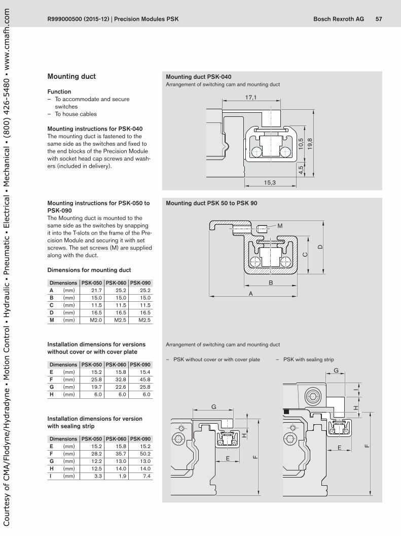
57Bosch Rexroth AG
E
G
HI
F
A
B
M
D
C
E
G
H
F
10,5
4,5
17,1
15,3
19,8
R999000500 (2015-12) | Precision Modules PSK
Mounting duct
Function – To accommodate and secure
switches – To house cables
Mounting instructions for PSK-040The mounting duct is fastened to the same side as the switches and fixed to the end blocks of the Precision Module with socket head cap screws and wash-ers (included in delivery).
Installation dimensions for versions without cover or with cover plate
Installation dimensions for version with sealing strip
– PSK without cover or with cover plate – PSK with sealing strip
Mounting duct PSK-040
Mounting duct PSK 50 to PSK 90Mounting instructions for PSK-050 to PSK-090The Mounting duct is mounted to the same side as the switches by snapping it into the T-slots on the frame of the Pre-cision Module and securing it with set screws. The set screws (M) are supplied along with the duct.
Dimensions for mounting duct
Dimensions PSK-050 PSK-060 PSK-090A (mm) 21.7 25.2 25.2B (mm) 15.0 15.0 15.0C (mm) 11.5 11.5 11.5D (mm) 16.5 16.5 16.5M (mm) M2.0 M2.5 M2.5
Dimensions PSK-050 PSK-060 PSK-090E (mm) 15.2 15.8 15.4F (mm) 25.8 32.8 45.8G (mm) 19.7 22.6 25.8H (mm) 6.0 6.0 6.0
Dimensions PSK-050 PSK-060 PSK-090E (mm) 15.2 15.8 15.2F (mm) 28.2 35.7 50.2G (mm) 12.2 13.0 13.0H (mm) 12.5 14.0 14.0I (mm) 3.3 1.9 7.4
Arrangement of switching cam and mounting duct
Arrangement of switching cam and mounting duct
Cou
rtes
y of
CM
A/F
lody
ne/H
ydra
dyne
▪ M
otio
n Con
trol
▪ H
ydra
ulic
▪ P
neum
atic
▪ E
lect
rica
l ▪ M
echa
nica
l ▪ (
800)
426
-548
0 ▪
ww
w.c
maf
h.co
m

58 Bosch Rexroth AG
35
3
5
6
6.5
Precision Modules PSK | R999000500 (2015-12)
Switch Mounting ArrangementsSwitches
The switches for Precision Modules PSK are magnetic field sensors with potted cable.
Versions – Hall sensor, PNP NC – Reed sensor (changeover)
Notes for mountingSwitches may only be mounted to one side of the Precision Module (left or right).A mounting duct is required for installa-tion of the switches.The switches are pushed into the slots of the mounting duct and fixed with set screws.
Set screw for fixing
Active surface
Hall sensorContact type PNP NCOperating voltage 3.8–30 V DCCurrent consumption max. 10 mAOutput current max. 20 mACable length 2000 mmProtection class IP 66Short-circuit protection No
Reed sensorContact type ChangeoverSwitching voltage max. 100 V DCSwitching current max. 500 mACable length 2000 mmProtection class IP 66Caution: 2 switching points
Pin assignment
Technical data
White: +3.8 ... 30 V DC
Green: Output
Brown: 0 V ground
Brown
White
Green
Hall sensor
Reed sensor
Attachments and Accessories
Cou
rtes
y of
CM
A/F
lody
ne/H
ydra
dyne
▪ M
otio
n Con
trol
▪ H
ydra
ulic
▪ P
neum
atic
▪ E
lect
rica
l ▪ M
echa
nica
l ▪ (
800)
426
-548
0 ▪
ww
w.c
maf
h.co
m

59Bosch Rexroth AGR999000500 (2015-12) | Precision Modules PSK
Cou
rtes
y of
CM
A/F
lody
ne/H
ydra
dyne
▪ M
otio
n Con
trol
▪ H
ydra
ulic
▪ P
neum
atic
▪ E
lect
rica
l ▪ M
echa
nica
l ▪ (
800)
426
-548
0 ▪
ww
w.c
maf
h.co
m

60 Bosch Rexroth AG
Mmax
M0
M (Nm)
n (min–1)
nmax
H
A
A
6032
45°
⌀F
⌀D
⌀E
⌀G
RLm
B1
C1C
H1
H2
Precision Modules PSK | R999000500 (2015-12)
Motor type nmax M0 Mmax Mbr Jm Jbr mm mbr
(min-1) (Nm) (Nm) (Nm) (kgm2) (kgm2) (kg) (kg)MSK 030C-0900 9 000 0,8 4,0 1 0,000030 0,000007 1,9 0,2MSK 040C-0600 7 500 2,7 8,1 4 0,000140 0,000023 3,6 0,3
IndraDyn S Servo Motor MSK
Motor data
Jbr = mass moment of inertia of the holding brake
Jm = mass moment of inertia, motorLm = length of the motorM0 = standstill torque
Mbr = holding torque of holding brake when switched off
Mmax = maximum possible motor torquenmax = maximum motor speed
Motor torque speed curve (schematic)
Motor type Dimensions (mm)A B1 C C1 ØD ØE ØF ØG H Lm
k6 j6 without brake
withbrake
MSK 030C-0900 54 7 20 2,5 9 40 63 4,5 98,5 180,0 213,0MSK 040C-0600 82 8 30 2,5 14 50 95 6,6 124,5 185,5 215,5
Attachments and Accessories
Cou
rtes
y of
CM
A/F
lody
ne/H
ydra
dyne
▪ M
otio
n Con
trol
▪ H
ydra
ulic
▪ P
neum
atic
▪ E
lect
rica
l ▪ M
echa
nica
l ▪ (
800)
426
-548
0 ▪
ww
w.c
maf
h.co
m

61Bosch Rexroth AGR999000500 (2015-12) | Precision Modules PSK
Motor ControllerMSK 030C-0900 HCS 01.1E-W0005MSK 030C-0900 HCS 01.1E-W0008MSK 040C-0600MSK 040C-0600 HCS 01.1E-W0018
Option number1) Motor Part number Version Type designationHolding brakewithout with
84 MSK 030C-0900 R911308683 X MSK030C-0900-NN-M1-UG0-NNNN85 R911308684 X MSK030C-0900-NN-M1-UG1-NNNN86 MSK 040C-0600 R911306060 X MSK040C-0600-NN-M1-UG0-NNNN87 R911306061 X MSK040C-0600-NN-M1-UG1-NNNN
1) From the “Configuration and Ordering” table“
Recommended motor controller combinations
Specification: – Plain shaft with shaft seal ring – Multiturn absolute encoder M1 (Hiperface) – Cooling system: natural convection – Protection class IP65 (casing) – With or without holding brake
NoteThe motors can be supplied complete with controllers and control units. For further motor types and more information on motors, controllers and control systems, please refer to the Rexroth catalogs on drive technology.
Cou
rtes
y of
CM
A/F
lody
ne/H
ydra
dyne
▪ M
otio
n Con
trol
▪ H
ydra
ulic
▪ P
neum
atic
▪ E
lect
rica
l ▪ M
echa
nica
l ▪ (
800)
426
-548
0 ▪
ww
w.c
maf
h.co
m

62 Bosch Rexroth AG
Mmax
M0
M (Nm)
n (min–1)
nmax
A⌀G
B1C1
C
⌀E
⌀D
Lm
⌀F H
Precision Modules PSK | R999000500 (2015-12)
Jbr = mass moment of inertia of the holding brake
Jm = mass moment of inertia, motorLm = length of the motorM0 = standstill torque
Mbr = holding torque of holding brake when switched off
Mmax = maximum possible motor torquenmax = maximum motor speed
Motor type nmax M0 Mmax Mbr Jm Jbr mm mbr
(min-1) (Nm) (Nm) (Nm) (kgm2) (kgm2) (kg) (kg)MSM 019A-0300 5 000 0.16 0.48 0.29 0.0000025 0.0000002 0.32 0.21MSM 019B-0300 5 000 0.32 0.95 0.29 0.0000051 0.0000002 0.47 0.21MSM 031B-0300 5 000 0.64 1.91 1.27 0.0000140 0.0000018 0.82 0.48MSM 031C-0300 5 000 1.30 3.80 1.27 0.0000260 0.0000018 1.20 0.50MSM 041B-0300 4 500 2.40 7.10 2.45 0.0000870 0.0000075 2.30 0.80
Motor data
IndraDyn S Servo Motor MSM
Motor torque speed curve (schematic)
Motor type Dimensions (mm)A B1 C C1 ØD ØE ØF ØG H Lm
h6 h7 without brake
withbrake
MSM 019A-0300 38 6,0 25 3 8 30 45 3,4 51 72,0 102,0MSM 019B-0300 38 6,0 25 3 8 30 45 3,4 51 92,0 122,0MSM 031B-0300 60 6,5 30 3 11 50 70 4,5 73 79,0 115,5MSM 031C-0300 60 6,5 30 3 14 50 70 4,5 73 98,5 135,0MSM 041B-0300 80 6,0 35 3 19 70 90 6,0 93 112,0 149,0
Attachments and Accessories
Cou
rtes
y of
CM
A/F
lody
ne/H
ydra
dyne
▪ M
otio
n Con
trol
▪ H
ydra
ulic
▪ P
neum
atic
▪ E
lect
rica
l ▪ M
echa
nica
l ▪ (
800)
426
-548
0 ▪
ww
w.c
maf
h.co
m
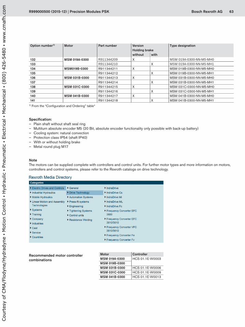
63Bosch Rexroth AGR999000500 (2015-12) | Precision Modules PSK
Option number1) Motor Part number Version Type designationHolding brakewithout with
132 MSM 019A-0300 R911344209 X MSM 019A-0300-NN-M5-MH0133 R911344210 X MSM 019A-0300-NN-M5-MH1134 MSM019B-0300 R911344211 X MSM 019B-0300-NN-M5-MH0135 R911344212 X MSM 019B-0300-NN-M5-MH1136 MSM 031B-0300 R911344213 X MSM 031B-0300-NN-M5-MH0137 R911344214 X MSM 031B-0300-NN-M5-MH1138 MSM 031C-0300 R911344215 X MSM 031C-0300-NN-M5-MH0139 R911344216 X MSM 031C-0300-NN-M5-MH1140 MSM 041B-0300 R911344217 X MSM 041B-0300-NN-M5-MH0141 R911344218 X MSM 041B-0300-NN-M5-MH1
1) From the “Configuration and Ordering” table“
Recommended motor controller combinations
Motor ControllerMSM 019A-0300 HCS 01.1E-W0003MSM 019B-0300MSM 031B-0300 HCS 01.1E-W0006MSM 031C-0300 HCS 01.1E-W0009MSM 041B-0300 HCS 01.1E-W0013
Specification: – Plain shaft without shaft seal ring – Multiturn absolute encoder M5 (20 Bit, absolute encoder functionality only possible with back-up battery) – Cooling system: natural convection – Protection class IP54 (shaft IP40) – With or without holding brake – Metal round plug M17
NoteThe motors can be supplied complete with controllers and control units. For further motor types and more information on motors, controllers and control systems, please refer to the Rexroth catalogs on drive technology.
Cou
rtes
y of
CM
A/F
lody
ne/H
ydra
dyne
▪ M
otio
n Con
trol
▪ H
ydra
ulic
▪ P
neum
atic
▪ E
lect
rica
l ▪ M
echa
nica
l ▪ (
800)
426
-548
0 ▪
ww
w.c
maf
h.co
m
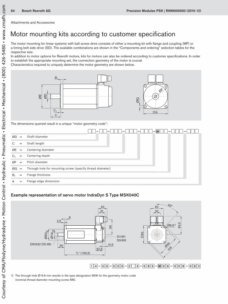
64 Bosch Rexroth AG
ØE
ØD
C
C1
B1
ØF
A
ØG
Ø50
j6
Ø14
k6
30 10,5
S1/M1S3/M3
82,5
DIN332 DS M542,5
“L” (155,5)
82
Ø6,61)
Ø95
109
83,5
69
3140
3260
45°
M
M1 4 3 0 0 5 5 59.20 0 0 0 0 08 86 2
Precision Modules PSK | R999000500 (2015-12)
The motor mounting for linear systems with ball screw drive consists of either a mounting kit with flange and coupling (MF) or a timing belt side drive (SD). The available combinations are shown in the “Components and ordering” selection tables for the respective size.In addition to motor options for Rexroth motors, kits for motors can also be ordered according to customer specifications. In order to establish the appropriate mounting set, the connection geometry of the motor is crucial. Characteristics required to uniquely determine the motor geometry are shown below.
The dimensions queried result in a unique “motor geometry code”:
1) The through hole Ø 6.6 mm results in the type designation M06 for the geometry motor code (nominal thread diameter mounting screw M6).
Example representation of servo motor IndraDyn S Type MSK040C
Motor mounting kits according to customer specification
ØD = Shaft diameter
C = Shaft length
ØE = Centering diameter
C1 = Centering depth
ØF = Pitch diameter
ØG = Through hole for mounting screw (specify thread diameter)
B1 = Flange thickness
A = Flange edge dimension
Attachments and Accessories
Cou
rtes
y of
CM
A/F
lody
ne/H
ydra
dyne
▪ M
otio
n Con
trol
▪ H
ydra
ulic
▪ P
neum
atic
▪ E
lect
rica
l ▪ M
echa
nica
l ▪ (
800)
426
-548
0 ▪
ww
w.c
maf
h.co
m
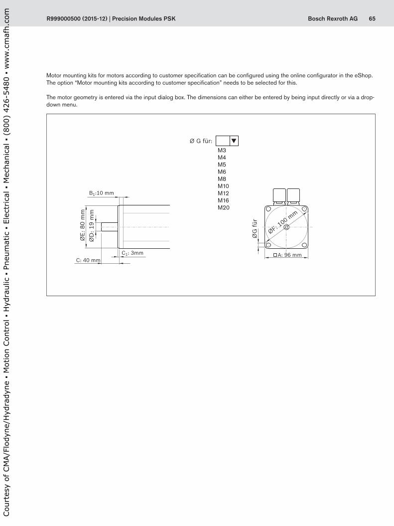
65Bosch Rexroth AG
ØE:
80
mm
ØD
: 19
mm
C: 40 mmC1: 3mm
B1:10 mm
A: 96 mmØ
G fü
r
ØF: 100 m
m
M3M4M5M6M8M10M12M16M20
Ø G für: �
ØE:
80
mm
ØD
: 19
mm
C: 40 mmC1: 3mm
B1:10 mm
A: 96 mmØ
G fü
r
ØF: 100 m
m
R999000500 (2015-12) | Precision Modules PSK
Motor mounting kits for motors according to customer specification can be configured using the online configurator in the eShop. The option “Motor mounting kits according to customer specification” needs to be selected for this.
The motor geometry is entered via the input dialog box. The dimensions can either be entered by being input directly or via a drop-down menu.
Cou
rtes
y of
CM
A/F
lody
ne/H
ydra
dyne
▪ M
otio
n Con
trol
▪ H
ydra
ulic
▪ P
neum
atic
▪ E
lect
rica
l ▪ M
echa
nica
l ▪ (
800)
426
-548
0 ▪
ww
w.c
maf
h.co
m
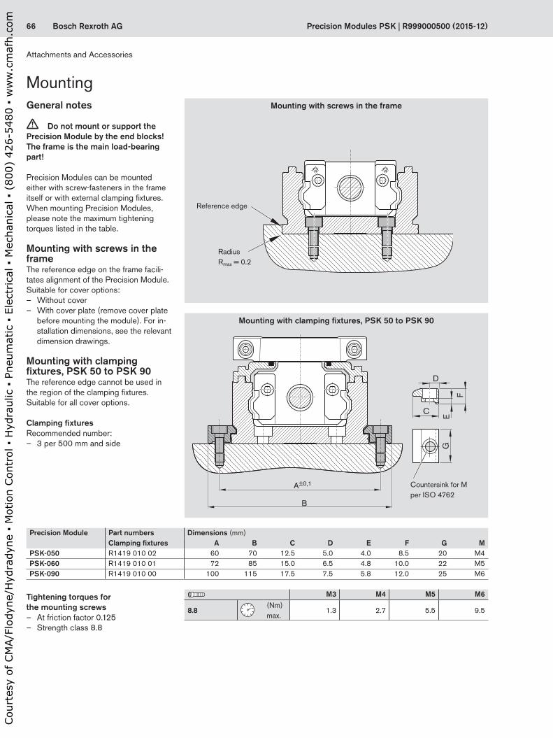
66 Bosch Rexroth AG
A±0,1
B
E
F
G
D
C
Precision Modules PSK | R999000500 (2015-12)
General notes
c Do not mount or support the Precision Module by the end blocks! The frame is the main load-bearing part!
Precision Modules can be mounted either with screw-fasteners in the frame itself or with external clamping fixtures.When mounting Precision Modules, please note the maximum tightening torques listed in the table.
Mounting with screws in the frameThe reference edge on the frame facili-tates alignment of the Precision Module.Suitable for cover options:
– Without cover – With cover plate (remove cover plate
before mounting the module). For in-stallation dimensions, see the relevant dimension drawings.
Mounting with clamping fixtures, PSK 50 to PSK 90The reference edge cannot be used in the region of the clamping fixtures.Suitable for all cover options.
Clamping fixturesRecommended number:
– 3 per 500 mm and side
Mounting
Countersink for M per ISO 4762
Tightening torques for the mounting screws
– At friction factor 0.125 – Strength class 8.8
Radius Rmax = 0.2
Reference edge
Mounting with clamping fixtures, PSK 50 to PSK 90
Mounting with screws in the frame
Precision Module Part numbers Dimensions (mm)Clamping fixtures A B C D E F G M
PSK-050 R1419 010 02 60 70 12.5 5.0 4.0 8.5 20 M4PSK-060 R1419 010 01 72 85 15.0 6.5 4.8 10.0 22 M5PSK-090 R1419 010 00 100 115 17.5 7.5 5.8 12.0 25 M6
M3 M4 M5 M6
8.8
(Nm)max.
1.3 2.7 5.5 9.5
Attachments and Accessories
Cou
rtes
y of
CM
A/F
lody
ne/H
ydra
dyne
▪ M
otio
n Con
trol
▪ H
ydra
ulic
▪ P
neum
atic
▪ E
lect
rica
l ▪ M
echa
nica
l ▪ (
800)
426
-548
0 ▪
ww
w.c
maf
h.co
m

67Bosch Rexroth AG
øEøD
F
M
C
A
C
A
C
B MMM
1 1
R999000500 (2015-12) | Precision Modules PSK
Lube PortsGeneral notesThe lubrication system on Precision Modules has been designed for grease lubricants (grease gun). The lube port supplies lubricant to both the Rail System guideway and the Precision Ball Screw Assembly. If the module has two carriages, both of these must be lubricated.
Lubricant
Without cover
Lube port for customer-built attachment
Customer-built attachment
O-ring
Carriage
Carriage: standard length Carriage: long
Cover plate Sealing strip
Precision Module PSK-040 PSK-050 PSK-060 PSK-090A (mm) 19.0 18.2 16.0 24.6B (mm) – – 22.0 33.3C (mm) 3.0 6.5 9.0 12.0D (mm) 2.5 2.5 2.5 4.0E (mm) 5.0 5.0 5.0 8.0F (mm) 0.6 +0.1 0.6 +0.1 0.7 +0.1 0.5 +0.1M (mm) M2 M2.5 M3 M4
Precision Module
O-ring DIN 3771
Part numbers
PSK-040 to PSK-060
3 x 1 R3411 118 01
PSK-090 5 x 1.5 R3411 108 01
PSK with cover plate or sealing stripOne-point lubrication at either of the two funnel-type lube nipples (1) DIN 3405-D3 per carriage.
For short-stroke applications, please contact us regarding the lubrication arrangements:PSK-040: stroke < 50 mmPSK-050: stroke < 70 mmPSK-060: stroke < 95 mmPSK-090: stroke < 135 mm
PSK-040Lube port for grease gun and for customer-built attachment
PSK-050 to PSK-090Funnel-type lube nipple DIN 3405-D3
PSK-040 PSK-050 to PSK-090
PSK without cover – PSK-040: One-point lubrication is pos-
sible via the lube port for grease gun on each carriage. Remove the set screw from the lube hole, apply lubricant, then drive the set screw in again.
– PSK-050 to PSK-090: One-point lubrica-tion at either of the two funnel-type lube nipples DIN 3405-D3 per carriage.
– One-point lubrication through customer-built attachment: This can be achieved in all PSK types by using the lube port in the carriage. The lube ports are closed with set screws for shipment. Before using the lube ports, the set screws must be removed and O-rings inserted to seal off the customer-built attachment.
Lithium soap grease
PSK-040 PSK-050 to PSK-090
Consistency class NGLI 00as per DIN 51818
Consistency classNLGI 2as per DIN 51818
Recommended Dynalub 520 Dynalub 510Part numbers R3416 043 00 R3416 037 00May also be used
ElkalubGLS 135 / N00
ElkalubGLS 135 / N2
Castrol LongtimePD 00, (Castrol)
Castrol LongtimePD 2, (Castrol)
Services and Information
Cou
rtes
y of
CM
A/F
lody
ne/H
ydra
dyne
▪ M
otio
n Con
trol
▪ H
ydra
ulic
▪ P
neum
atic
▪ E
lect
rica
l ▪ M
echa
nica
l ▪ (
800)
426
-548
0 ▪
ww
w.c
maf
h.co
m

68 Bosch Rexroth AG
M (
Nm
)
0
t (ms)
0
s (mm)0
s (mm)110 220 330 440 5500
–1,0
1,0
–0,5
0,50,0
1,52,02,5
–2,5–2,0–1,5
Precision Modules PSK | R999000500 (2015-12)
Friction moment M
Friction moment M
Advance ReturnExample
Checks listed in the standard report:– Functional checks of mechanical
components– Functional checks of electrical
components– Design is in accordance with order
confirmation
DocumentationThe standard report serves to confirm that the checks listed in the report have been carried out and that the measured values lie within the permissible toler-ances.
Standard report
Option no. 01
Frictional moment of complete system
Option no. 02
The moment of friction M is measured over the entire travel range.
Several measuring points are passed during the total travel. The yawing and pitching deviations are measured at these points.
NoteThe measurements are taken with the module screwed down and assuming an ideally flat mounting base surface.
Lead deviation of ball screw
Option no. 03
A measurement report of the lead devia-tion d over the measured travel s (see illustration) is provided in table form in addition to the graph.
Travel accuracy
Option no. 04
YawingYawing is angular deviation about the vertical axis. This angular deviation is converted to a linear deviation d in µm on the basis of a standard length and is plotted on the graph. The base length is given in the graph.
Example
Example
Base length 100 mm
“Yaw”
Vertical axis
M = friction moment (N)t = travel time (ms)
d = deviation (mm)s = measured travel (mm)
Services and Information
Cou
rtes
y of
CM
A/F
lody
ne/H
ydra
dyne
▪ M
otio
n Con
trol
▪ H
ydra
ulic
▪ P
neum
atic
▪ E
lect
rica
l ▪ M
echa
nica
l ▪ (
800)
426
-548
0 ▪
ww
w.c
maf
h.co
m

69Bosch Rexroth AG
s (mm)110 220 330 440 5500
–1,0
1,0
–0,5
0,5
0,0
1,5
–2,5
–3,0
–3,5
–4,0
–2,0
–1,5
s (mm)
25
–25
–50
–75
–100
0
175 252,5 350 612,5 7000 87,5 437,5 525
Pa
P
Ps/
2P
s/2
U
R999000500 (2015-12) | Precision Modules PSK
Base length 100 mm
Example
Positioning accuracy per VDI/DGQ 3441
Option no. 05
Measurement points are selected at irregular intervals along the travel range. This allows even periodical deviations d in µm to be detected during positioning.Each measurement point is approached several times from both sides.This gives the following parameters.
PitchingPitching means angular deviation about the horizontal axis. This angular deviation is converted to a linear deviation d in µm on the basis of a standard length and is plotted on the graph. The base length is given in the graph.In addition to graphical representation (see illustrations), a measurement report is supplied in table form.
“Pitch”
Horizontal axis
Positioning accuracy P The positioning accuracy corresponds to the total deviation. It encompasses all the systematic and random deviations during positioning. The positioning
Reversal range U
Example
Position deviation Pa
Position variation range Ps
accuracy takes the following characteris-tic values into consideration:– Position deviation– Reversal range– Position variation range
The position deviation corresponds to the maximum difference arising in the mean values of all the measurement points. It describes systematic deviations.
The reversal range corresponds to the difference in mean values of the two approach directions.
The reversal range is determined at every measurement point. It describes systematic deviations.
The position variation range describes the effects of random deviations. It is determined at every measurement point.
d = deviation (mm)s = measured travel (mm)
Cou
rtes
y of
CM
A/F
lody
ne/H
ydra
dyne
▪ M
otio
n Con
trol
▪ H
ydra
ulic
▪ P
neum
atic
▪ E
lect
rica
l ▪ M
echa
nica
l ▪ (
800)
426
-548
0 ▪
ww
w.c
maf
h.co
m

70 Bosch Rexroth AG Precision Modules PSK | R999000500 (2015-12)
Ambient temperature (Temperature must not fall below dew point)
0 °C ... 40 °C
ϑ
Load ≤ 0,2 C
Travel speed ≤ 1,0 m/s
v
Traveldistance smin
PSK-040 > 65 mm
PSK-050 > 70 mm
PSK-060 > 95 mm
PSK-090 > 135 mm
Contamination Not permitted
Normal operating conditions
Operating conditions and usage
Required and supplementary documentation
For more information about Intended use and safety, see “Safety Instructions for Linear Motion Systems R320103152”.
For more information on installation / initial operation see “Instructions PSK R320103187”.
PDF files of these documents can be found on the Internet at:www.boschrexroth.com/mediadirectory
Services and Information
Cou
rtes
y of
CM
A/F
lody
ne/H
ydra
dyne
▪ M
otio
n Con
trol
▪ H
ydra
ulic
▪ P
neum
atic
▪ E
lect
rica
l ▪ M
echa
nica
l ▪ (
800)
426
-548
0 ▪
ww
w.c
maf
h.co
m
71Bosch Rexroth AGR999000500 (2015-12) | Precision Modules PSK
Further InformationHomepage Bosch Rexroth: http://www.boschrexroth.com
Productinformations Precision Modules: http://www.boschrexroth.com/en/xc/products/prod-uct-groups/linear-motion-technology/linear-motion-sys-tems/precision-modules/index
Cou
rtes
y of
CM
A/F
lody
ne/H
ydra
dyne
▪ M
otio
n Con
trol
▪ H
ydra
ulic
▪ P
neum
atic
▪ E
lect
rica
l ▪ M
echa
nica
l ▪ (
800)
426
-548
0 ▪
ww
w.c
maf
h.co
m

72 Bosch Rexroth AG Precision Modules PSK | R999000500 (2015-12)
Rexroth Precision Module PSK
Telephone +49 9721 937-0Telefax +49 9721 937-350 (direct)
Inquiry/Order Form
Quantity Order of: ____ pcs, _____ per month, ______ per year, per order, or ________________________________Comments:______________________________________________________________________________________________________________FromCompany: ___________________________________ Name: _______________________________________________
Address: ____________________________________ Department: __________________________________________
_____________________________________________ Telephone: ___________________________________________
_____________________________________________ Telefax: ______________________________________________
Bosch Rexroth AGLinear Motion and Assembly TechnologiesD-97419 SchweinfurtGermany
Ordering data DescriptionPrecision Module PSK-090 Designation Part number: PSK-090-NN-1, 740 mm PSK-090, length = 740 mmVersion = MF01 With motor mount and motor, as shown in diagram MF01Guideway = 18 Rail system, 740 mm longDrive unit = 03 Ball screw 16 x 16Carriage = 24 Two carriages, long, steel version for cover plateMotor attachment = 03 With motor mount for motor MSK 040CMotor = 87 Motor MSK 040C with brakeCover = 01 With cover plate1st switch = 21 Reed sensor supplied loose2nd switch = 22 Hall sensor supplied loose3rd switch = 21 Reed sensor supplied looseMounting duct = 25 Mounting duct supplied looseSwitching cam = 30 Switching cam for version without cover or with cover plateDocumentation = 01 Standard report
Ordering example
1) Only required for „kits for motors according to customer specifications“.
M
To be completed by customer: Inquiry / OrderPrecision Module
Part number: PSK-_______ -NN-1, length __________mm
Version = Guideway = Drive unit = Carriage = Carriage with center-to-center distanceMotor attachment = Motor geometry code1)
Motor = Cover = 1st switch = 2nd switch = 3rd switch = Mounting duct = Switching cam = Documentation =
Services and Information
Cou
rtes
y of
CM
A/F
lody
ne/H
ydra
dyne
▪ M
otio
n Con
trol
▪ H
ydra
ulic
▪ P
neum
atic
▪ E
lect
rica
l ▪ M
echa
nica
l ▪ (
800)
426
-548
0 ▪
ww
w.c
maf
h.co
m

73Bosch Rexroth AGR999000500 (2015-12) | Precision Modules PSK
Cou
rtes
y of
CM
A/F
lody
ne/H
ydra
dyne
▪ M
otio
n Con
trol
▪ H
ydra
ulic
▪ P
neum
atic
▪ E
lect
rica
l ▪ M
echa
nica
l ▪ (
800)
426
-548
0 ▪
ww
w.c
maf
h.co
m

74 Bosch Rexroth AG Precision Modules PSK | R999000500 (2015-12)
Cou
rtes
y of
CM
A/F
lody
ne/H
ydra
dyne
▪ M
otio
n Con
trol
▪ H
ydra
ulic
▪ P
neum
atic
▪ E
lect
rica
l ▪ M
echa
nica
l ▪ (
800)
426
-548
0 ▪
ww
w.c
maf
h.co
m
75Bosch Rexroth AGR999000500 (2015-12) | Precision Modules PSK
Cou
rtes
y of
CM
A/F
lody
ne/H
ydra
dyne
▪ M
otio
n Con
trol
▪ H
ydra
ulic
▪ P
neum
atic
▪ E
lect
rica
l ▪ M
echa
nica
l ▪ (
800)
426
-548
0 ▪
ww
w.c
maf
h.co
m
Find your local contact person here:www.boschrexroth.com/contact
Bosch Rexroth AGErnst-Sachs-Straße 10097424 Schweinfurt, GermanyTel. +49 9721 937-0 Fax +49 9721 937-275www.boschrexroth.com
R999000500 (2015-12)© Bosch Rexroth AG 2015Subject to revisions!
The data specified above only serve to describe the product.As our products are constantly being further developed, no statements concerning a certain condition or suitability for a certain application can be derived from our information. The information given does not release the user from the obligation of own judgment and verification. It must be remembered that our products are subject to a natural process of wear and aging.
Cou
rtes
y of
CM
A/F
lody
ne/H
ydra
dyne
▪ M
otio
n Con
trol
▪ H
ydra
ulic
▪ P
neum
atic
▪ E
lect
rica
l ▪ M
echa
nica
l ▪ (
800)
426
-548
0 ▪
ww
w.c
maf
h.co
m