Precision, Micro Power Hall-Effect Angle Sensor IC · Precision, Micro Power Hall-Effect Angle...
15
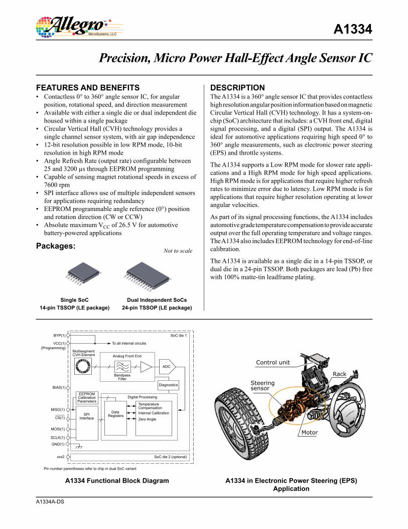
A1334A-DS Precision, Micro Power Hall-Effect Angle Sensor IC A1334 The A1334 is a 360° angle sensor IC that provides contactless high resolution angular position information based on magnetic Circular Vertical Hall (CVH) technology. It has a system-on- chip (SoC) architecture that includes: a CVH front end, digital signal processing, and a digital (SPI) output. The A1334 is ideal for automotive applications requiring high speed 0° to 360° angle measurements, such as electronic power steering (EPS) and throttle systems. The A1334 supports a Low RPM mode for slower rate appli- cations and a High RPM mode for high speed applications. High RPM mode is for applications that require higher refresh rates to minimize error due to latency. Low RPM mode is for applications that require higher resolution operating at lower angular velocities. As part of its signal processing functions, the A1334 includes automotive grade temperature compensation to provide accurate output over the full operating temperature and voltage ranges. The A1334 also includes EEPROM technology for end-of-line calibration. The A1334 is available as a single die in a 14-pin TSSOP, or dual die in a 24-pin TSSOP. Both packages are lead (Pb) free with 100% matte-tin leadframe plating. Packages: Not to scale A1334 Functional Block Diagram A1334 in Electronic Power Steering (EPS) Application Multisegment CVH Element Analog Front End To all internal circuits Bandpass Filter Digital Processing Temperature Compensation Internal Calibration Zero Angle Data Registers EEPROM Calibration Parameters SPI Interface Diagnostics BYP(1) SoC die 1 SoC die 2 (optional) VCC(1) MOSI(1) SCLK(1) MISO(1) GND(1) xxx2 ADC BIAS(1) CS(1) (Programming) Pin number parentheses refer to chip in dual SoC variant Control unit Rack Motor Steering sensor Single SoC 14-pin TSSOP (LE package) Dual Independent SoCs 24-pin TSSOP (LE package) • Contactless 0° to 360° angle sensor IC, for angular position, rotational speed, and direction measurement • Available with either a single die or dual independent die housed within a single package • Circular Vertical Hall (CVH) technology provides a single channel sensor system, with air gap independence • 12-bit resolution possible in low RPM mode, 10-bit resolution in high RPM mode • Angle Refresh Rate (output rate) configurable between 25 and 3200 µs through EEPROM programming • Capable of sensing magnet rotational speeds in excess of 7600 rpm • SPI interface allows use of multiple independent sensors for applications requiring redundancy • EEPROM programmable angle reference (0°) position and rotation direction (CW or CCW) • Absolute maximum V CC of 26.5 V for automotive battery-powered applications FEATURES AND BENEFITS DESCRIPTION
-
Upload
nguyenduong -
Category
Documents
-
view
234 -
download
0
Transcript of Precision, Micro Power Hall-Effect Angle Sensor IC · Precision, Micro Power Hall-Effect Angle...
A1334A-DS
Precision, Micro Power Hall-Effect Angle Sensor IC
A1334
The A1334 is a 360° angle sensor IC that provides contactless high resolution angular position information based on magnetic Circular Vertical Hall (CVH) technology. It has a system-on-chip (SoC) architecture that includes: a CVH front end, digital signal processing, and a digital (SPI) output. The A1334 is ideal for automotive applications requiring high speed 0° to 360° angle measurements, such as electronic power steering (EPS) and throttle systems.
The A1334 supports a Low RPM mode for slower rate appli-cations and a High RPM mode for high speed applications. High RPM mode is for applications that require higher refresh rates to minimize error due to latency. Low RPM mode is for applications that require higher resolution operating at lower angular velocities.
As part of its signal processing functions, the A1334 includes automotive grade temperature compensation to provide accurate output over the full operating temperature and voltage ranges. The A1334 also includes EEPROM technology for end-of-line calibration.
The A1334 is available as a single die in a 14-pin TSSOP, or dual die in a 24-pin TSSOP. Both packages are lead (Pb) free with 100% matte-tin leadframe plating.
Packages:Not to scale
A1334 Functional Block Diagram A1334 in Electronic Power Steering (EPS) Application
MultisegmentCVH Element Analog Front End
To all internal circuits
BandpassFilter
Digital Processing
TemperatureCompensationInternal Calibration
Zero Angle
Data Registers
EEPROMCalibrationParameters
SPIInterface
Diagnostics
BYP(1) SoC die 1
SoC die 2 (optional)
VCC(1)
MOSI(1)
SCLK(1)
MISO(1)
GND(1)
xxx2
ADC
BIAS(1)
CS(1)
(Programming)
Pin number parentheses refer to chip in dual SoC variant
Control unit
Rack
Motor
Steeringsensor
Single SoC14-pin TSSOP (LE package)
Dual Independent SoCs24-pin TSSOP (LE package)
• Contactless 0° to 360° angle sensor IC, for angular position, rotational speed, and direction measurement
• Available with either a single die or dual independent die housed within a single package
• Circular Vertical Hall (CVH) technology provides a single channel sensor system, with air gap independence
• 12-bit resolution possible in low RPM mode, 10-bit resolution in high RPM mode
• Angle Refresh Rate (output rate) configurable between 25 and 3200 µs through EEPROM programming
• Capable of sensing magnet rotational speeds in excess of 7600 rpm
• SPI interface allows use of multiple independent sensors for applications requiring redundancy
• EEPROM programmable angle reference (0°) position and rotation direction (CW or CCW)
• Absolute maximum VCC of 26.5 V for automotive battery-powered applications
FEATURES AND BENEFITS DESCRIPTION
Precision, Micro Power Hall-Effect Angle Sensor ICA1334
2Allegro MicroSystems, LLC115 Northeast CutoffWorcester, Massachusetts 01615-0036 U.S.A.1.508.853.5000; www.allegromicro.com
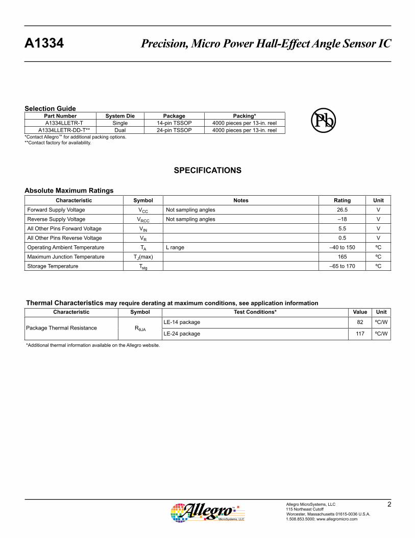
Absolute Maximum RatingsCharacteristic Symbol Notes Rating Unit
Forward Supply Voltage VCC Not sampling angles 26.5 V
Reverse Supply Voltage VRCC Not sampling angles –18 V
All Other Pins Forward Voltage VIN 5.5 V
All Other Pins Reverse Voltage VR 0.5 V
Operating Ambient Temperature TA L range –40 to 150 ºC
Maximum Junction Temperature TJ(max) 165 ºC
Storage Temperature Tstg –65 to 170 ºC
Selection GuidePart Number System Die Package Packing*A1334LLETR-T Single 14-pin TSSOP 4000 pieces per 13-in. reel
A1334LLETR-DD-T** Dual 24-pin TSSOP 4000 pieces per 13-in. reel*Contact Allegro™ for additional packing options.**Contact factory for availability.
SPECIFICATIONS
Thermal Characteristics may require derating at maximum conditions, see application informationCharacteristic Symbol Test Conditions* Value Unit
Package Thermal Resistance RθJA
LE-14 package 82 ºC/W
LE-24 package 117 ºC/W
*Additional thermal information available on the Allegro website.
Precision, Micro Power Hall-Effect Angle Sensor ICA1334
3Allegro MicroSystems, LLC115 Northeast CutoffWorcester, Massachusetts 01615-0036 U.S.A.1.508.853.5000; www.allegromicro.com
VCC
A1334
VCC_1
SCLK_1
SCLK_2
MISO_1
MOSI_1
MOSI_2
MISO_2
BYP_1 VCC_2 BYP_2
BIAS_2
BIAS_1
AGND_2AGND_1 DGND_2DGND_1
0.1 µF
0.1 µF 0.1 µF
Host
Microprocessor
CS_1
CS_2
TargetMagnet
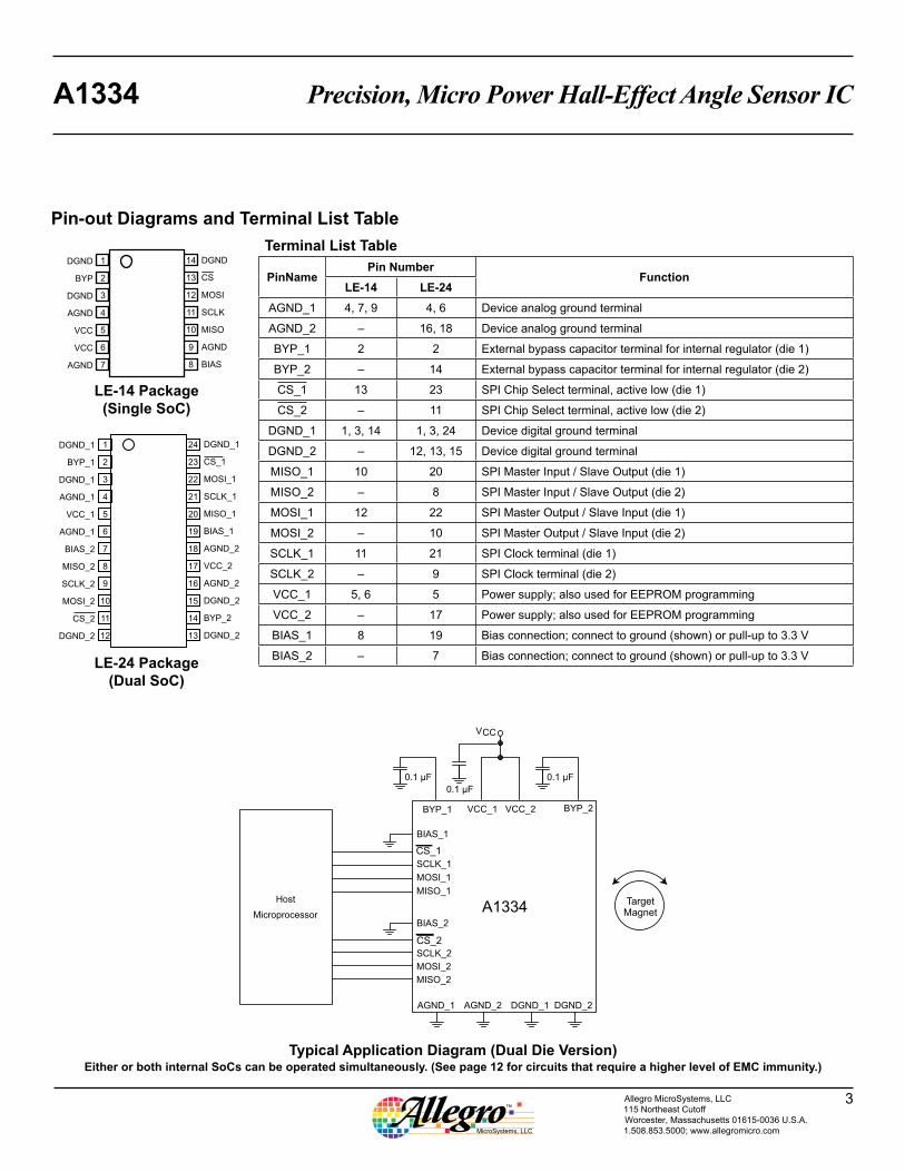
Typical Application Diagram (Dual Die Version)Either or both internal SoCs can be operated simultaneously. (See page 12 for circuits that require a higher level of EMC immunity.)
Terminal List Table
PinNamePin Number
FunctionLE-14 LE-24
AGND_1 4, 7, 9 4, 6 Device analog ground terminal
AGND_2 – 16, 18 Device analog ground terminal
BYP_1 2 2 External bypass capacitor terminal for internal regulator (die 1)
BYP_2 – 14 External bypass capacitor terminal for internal regulator (die 2)
CS_1 13 23 SPI Chip Select terminal, active low (die 1)
CS_2 – 11 SPI Chip Select terminal, active low (die 2)
DGND_1 1, 3, 14 1, 3, 24 Device digital ground terminal
DGND_2 – 12, 13, 15 Device digital ground terminal
MISO_1 10 20 SPI Master Input / Slave Output (die 1)
MISO_2 – 8 SPI Master Input / Slave Output (die 2)
MOSI_1 12 22 SPI Master Output / Slave Input (die 1)
MOSI_2 – 10 SPI Master Output / Slave Input (die 2)
SCLK_1 11 21 SPI Clock terminal (die 1)
SCLK_2 – 9 SPI Clock terminal (die 2)
VCC_1 5, 6 5 Power supply; also used for EEPROM programming
VCC_2 – 17 Power supply; also used for EEPROM programming
BIAS_1 8 19 Bias connection; connect to ground (shown) or pull-up to 3.3 V
BIAS_2 – 7 Bias connection; connect to ground (shown) or pull-up to 3.3 V
Pin-out Diagrams and Terminal List Table
DGND_1
BYP_1
DGND_1
AGND_1
VCC_1
AGND_1
BIAS_2
MISO_2
SCLK_2
MOSI_2
CS_2
DGND_2
DGND_1
CS_1
MOSI_1
SCLK_1
MISO_1
BIAS_1
AGND_2
VCC_2
AGND_2
DGND_2
BYP_2
DGND_2
1
2
3
4
5
6
7
8
9
10
11
12
24
23
22
21
20
19
18
17
16
15
14
13
LE-14 Package(Single SoC)
LE-24 Package(Dual SoC)
DGND
BYP
DGND
AGND
VCC
VCC
AGND
1
2
3
4
5
6
7
14
13
12
11
10
9
8
DGND
CS
MOSI
SCLK
MISO
AGND
BIAS
Precision, Micro Power Hall-Effect Angle Sensor ICA1334
4Allegro MicroSystems, LLC115 Northeast CutoffWorcester, Massachusetts 01615-0036 U.S.A.1.508.853.5000; www.allegromicro.com
Continued on the next page…
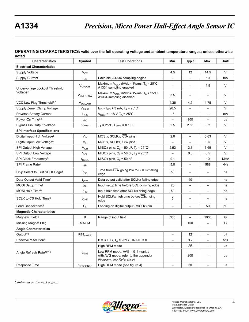
OPERATING CHARACTERISTICS: valid over the full operating voltage and ambient temperature ranges; unless otherwise noted
Characteristics Symbol Test Conditions Min. Typ.1 Max. Unit2
Electrical CharacteristicsSupply Voltage VCC 4.5 12 14.5 V
Supply Current ICC Each die, A1334 sampling angles – – 10 mA
Undervoltage Lockout Threshold Voltage3
VUVLOHIMaximum VCC , dV/dt = 1V/ms, TA = 25°C, A1334 sampling enabled – – 4.5 V
VUVLOLOWMaximum VCC , dV/dt = 1V/ms, TA = 25°C, A1334 sampling disabled 3.5 – – V
VCC Low Flag Threshold4,5 VUVLOTH 4.35 4.5 4.75 V
Supply Zener Clamp Voltage VZSUP ICC = ICC + 3 mA, TA = 25°C 26.5 – – V
Reverse Battery Current IRCC VRCC = –18 V, TA = 25°C –5 – – mA
Power-On Time6,8 tPO – 300 – µs
Bypass Pin Output Voltage VBYP TA = 25°C, CBYP = 0.1 µF 2.5 2.85 3.2 V
SPI Interface SpecificationsDigital Input High Voltage8 VIH MOSIx, SCLKx, ̄C̄ ̄S̄ x pins 2.8 – 3.63 V
Digital Input Low Voltage8 VIL MOSIx, SCLKx, ̄C̄ ̄S̄ x pins – – 0.5 V
SPI Output High Voltage VOH MISOx pins, CL = 50 pF, TA = 25°C 2.93 3.3 3.69 V
SPI Output Low Voltage VOL MISOx pins, CL = 50 pF, TA = 25°C – 0.3 0.5 V
SPI Clock Frequency8 fSCLK MISOx pins, CL = 50 pF 0.1 – 10 MHz
SPI Frame Rate8 tSPI 5.8 – 588 kHz
Chip Select to First SCLK Edge8 tCSTime from ̄C̄ ̄S̄ x going low to SCLKx falling edge 50 – – ns
Data Output Valid Time8 tDAV Data output valid after SCLKx falling edge – 40 – ns
MOSI Setup Time8 tSU Input setup time before SCLKx rising edge 25 – – ns
MOSI Hold Time8 tHD Input hold time after SCLKx rising edge 50 – – ns
SCLK to CS Hold Time8 tCHDHold SCLKx high time before ̄C̄ ̄S̄ x rising edge 5 – – ns
Load Capacitance8 CL Loading on digital output (MISOx) pin – – 50 pF
Magnetic CharacteristicsMagnetic Field9 B Range of input field 300 – 1000 G
Missing Magnet Flag MAGM 100 – G
Angle CharacteristicsOutput10 RESANGLE – 12 – bit
Effective resolution11 B = 300 G, TA = 25ºC, ORATE = 0 – 9.2 – bits
Angle Refresh Rate12,13 tANG
High RPM mode – 25 – µs
Low RPM mode, AVG = 011 (varies with AVG mode, refer to the appendix Programming Reference)
– 200 – µs
Response Time tRESPONSE High RPM mode (see figure 4) – 60 – µs
Precision, Micro Power Hall-Effect Angle Sensor ICA1334
5Allegro MicroSystems, LLC115 Northeast CutoffWorcester, Massachusetts 01615-0036 U.S.A.1.508.853.5000; www.allegromicro.com
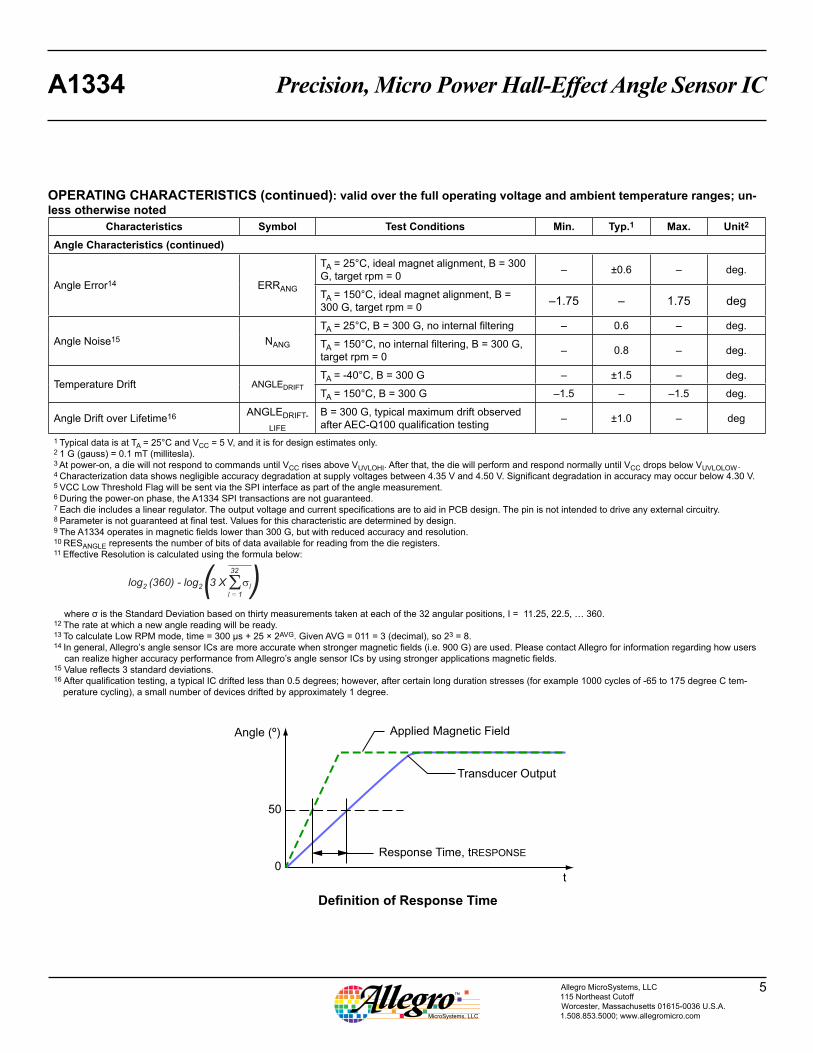
OPERATING CHARACTERISTICS (continued): valid over the full operating voltage and ambient temperature ranges; un-less otherwise noted
Characteristics Symbol Test Conditions Min. Typ.1 Max. Unit2
Angle Characteristics (continued)
Angle Error14 ERRANG
TA = 25°C, ideal magnet alignment, B = 300 G, target rpm = 0 – ±0.6 – deg.
TA = 150°C, ideal magnet alignment, B = 300 G, target rpm = 0 –1.75 – 1.75 deg
Angle Noise15 NANG
TA = 25°C, B = 300 G, no internal filtering – 0.6 – deg.
TA = 150°C, no internal filtering, B = 300 G, target rpm = 0 – 0.8 – deg.
Temperature Drift ANGLEDRIFTTA = -40°C, B = 300 G – ±1.5 – deg.
TA = 150°C, B = 300 G –1.5 – –1.5 deg.
Angle Drift over Lifetime16 ANGLEDRIFT-LIFE
B = 300 G, typical maximum drift observed after AEC-Q100 qualification testing – ±1.0 – deg
1 Typical data is at TA = 25°C and VCC = 5 V, and it is for design estimates only.2 1 G (gauss) = 0.1 mT (millitesla).3 At power-on, a die will not respond to commands until VCC rises above VUVLOHI. After that, the die will perform and respond normally until VCC drops below VUVLOLOW .4 Characterization data shows negligible accuracy degradation at supply voltages between 4.35 V and 4.50 V. Significant degradation in accuracy may occur below 4.30 V.5 VCC Low Threshold Flag will be sent via the SPI interface as part of the angle measurement.6 During the power-on phase, the A1334 SPI transactions are not guaranteed.7 Each die includes a linear regulator. The output voltage and current specifications are to aid in PCB design. The pin is not intended to drive any external circuitry.8 Parameter is not guaranteed at final test. Values for this characteristic are determined by design.9 The A1334 operates in magnetic fields lower than 300 G, but with reduced accuracy and resolution.10 RESANGLE represents the number of bits of data available for reading from the die registers. 11 Effective Resolution is calculated using the formula below:
log2 2(360) - log (3 X ��)32
l
l = 1
where σ is the Standard Deviation based on thirty measurements taken at each of the 32 angular positions, I = 11.25, 22.5, … 360. 12 The rate at which a new angle reading will be ready.13 To calculate Low RPM mode, time = 300 µs + 25 × 2AVG. Given AVG = 011 = 3 (decimal), so 23 = 8.14 In general, Allegro’s angle sensor ICs are more accurate when stronger magnetic fields (i.e. 900 G) are used. Please contact Allegro for information regarding how users
can realize higher accuracy performance from Allegro’s angle sensor ICs by using stronger applications magnetic fields.15 Value reflects 3 standard deviations.16 After qualification testing, a typical IC drifted less than 0.5 degrees; however, after certain long duration stresses (for example 1000 cycles of -65 to 175 degree C tem-
perature cycling), a small number of devices drifted by approximately 1 degree.
Applied Magnetic Field
Transducer Output
50
0
Angle (º)
Response Time, tRESPONSE
t
Definition of Response Time
Precision, Micro Power Hall-Effect Angle Sensor ICA1334
6Allegro MicroSystems, LLC115 Northeast CutoffWorcester, Massachusetts 01615-0036 U.S.A.1.508.853.5000; www.allegromicro.com
FUNCTIONAL DESCRIPTION
Operational ModesThe A1334 angle sensor device is designed to support a wide variety of automotive applications requiring measuring 0° to 360° angle positions.
An option for two electrically-independent die in the same package provides solid-state consistency and reliability. Each die SPI port can be configured in a different RPM mode. The data output selection is controlled by the address request in the SPI Read command.
The A1334 has dual identical system-on-chip (SoC) architecture. The output of each die is used by the host microcontroller to provide a single channel of target data.
Angle MeasurementThe A1334 can monitor the angular position of a rotating magnet at speeds ranging from 0 to more than 7600 rpm. At lower rotational speeds, the A1334 provides high resolution angle mea-surement accuracy. It can also support higher rates of rotational speeds at reduced levels of angle measurement accuracy.
The A1334 can be configured to operate in two angular measure-ment modes of operation: Low RPM mode, and High RPM mode. For applications that have a speed range from 0 to 500 rpm (can vary with AVG), the Low RPM mode provides increased resolu-tion. For applications above 500 rpm, configuring the A1334 in High RPM mode provides angle measurements with standard resolution. Above 7600 rpm the A1334 continues to provide angle data, however the accuracy is proportionally reduced.
The actual update rate of Low RPM mode can be changed by setting the AVG bits in the EEPROM. (See the appendix Program-ming Reference for details.) The selection of Low RPM mode or High RPM mode can be programmed, via the Angle_Meas_Mode bit, for the expected maximum rotational speed of the magnet in operation, to provide the highest corresponding level of angle accuracy. However, the A1334 provides valid output data regard-less of the selected mode and the application speed.
Although the range of the resolution of the measurement data output, RESANGLE, is determined by the selection of either High RPM or Low RPM mode, the measurement is also affected by the intensity (B, in gauss) of the applied magnetic field from the target. At lower intensities, a reduced signal-to-noise ratio will cause one or two LSBs to change state randomly due to noise, and the effective DAC resolution is reduced. These factors work
together, so when High RPM mode is selected, the effective range of resolution is 8 to 10 bits (from lower to higher field intensities), and in Low RPM mode, the effective range is 11 to 12 bits, depending on field strength and AVG selection.
Regardless of the field intensity and mode selection, the transmis-sion protocol and number formatting remains the same. The MSB is always transmitted first. The entire number should be read.
The Output Angle is always calculated at maximum resolution. To be more explicit:
AngleOUT = 360 (°) × D[12:0] / (213) (1)
This formula is always true, regardless of the applied field intensity. What changes with the field and speed setting is how uniform the LSBs of the measurement data (D 12:x) will be.
When using the dual die version of the A1334, it should be noted that the secondary die (E2) is rotated 180° relative to the primary die (E1). This results in a difference in measurement of approxi-mately 180° between the two die, given perfect alignment of each die to the target magnet.
This phenomenon can be counteracted by subtracting the offset using a microprocessor. Alternatively, the difference between the two die can be compensated for using the EEPROM for setting the Reference Angle.
System Level TimingThe A1334 outputs a new angle measurement every tANG µs. In High RPM mode, the A1334 outputs a new angle measurement every tANG µs, with an effective resolution of 10 bits. There is, however, a latency of tLAT , from when the rotating magnet is sampled by the CVH to when the sampled data has been completely transmitted over the SPI interface. Because an SPI interface Read command is not synchronous with the CVH tim-ing, but instead is polled by the external host microcontroller, the latency can vary. For single back-to-back SPI transactions (first transaction is sending the Read register 0x0 command, second is retrieving the angle data) the following scenarios are possible:
• Worst case: 2 CVH cycle + 2 SPI cycles
• Best case: 1.5 SPI cycles; 2 µs, assuming a 10 MHz SPI clock
Power-upUpon applying power to the A1334, the device automatically runs through an initialization routine. The purpose of this initialization
Precision, Micro Power Hall-Effect Angle Sensor ICA1334
7Allegro MicroSystems, LLC115 Northeast CutoffWorcester, Massachusetts 01615-0036 U.S.A.1.508.853.5000; www.allegromicro.com
is to ensure that the device comes up in the same predictable operating condition every power cycle. This initialization routine takes a finite amount of time to complete, which is referred to as Power-On Time, tPO .
The A1334 wakes up in a default state that sets all SPI registers to their default value. It is important to note that, regardless of the state of the device before a power cycle, the device will re-power with default values. For example, on every power-up, the device will power up in the mode set in the EEPROM bit RPM. The state of the EEPROM is unchanged.
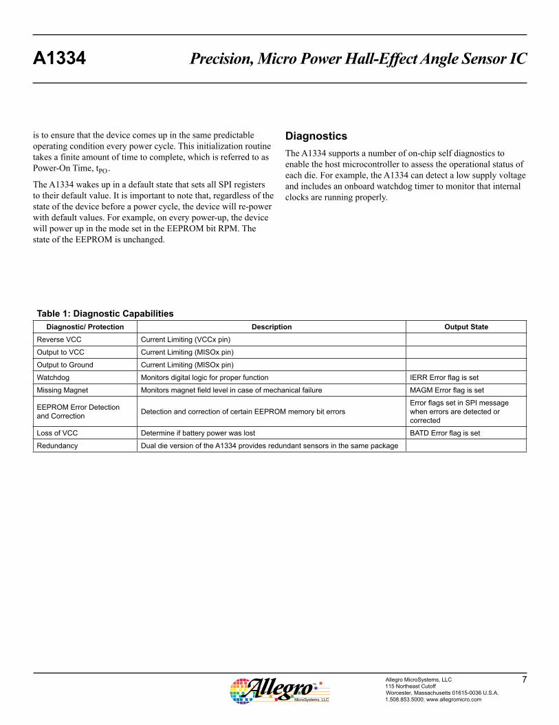
DiagnosticsThe A1334 supports a number of on-chip self diagnostics to enable the host microcontroller to assess the operational status of each die. For example, the A1334 can detect a low supply voltage and includes an onboard watchdog timer to monitor that internal clocks are running properly.
Table 1: Diagnostic CapabilitiesDiagnostic/ Protection Description Output State
Reverse VCC Current Limiting (VCCx pin)
Output to VCC Current Limiting (MISOx pin)
Output to Ground Current Limiting (MISOx pin)
Watchdog Monitors digital logic for proper function IERR Error flag is set
Missing Magnet Monitors magnet field level in case of mechanical failure MAGM Error flag is set
EEPROM Error Detection and Correction Detection and correction of certain EEPROM memory bit errors
Error flags set in SPI message when errors are detected or corrected
Loss of VCC Determine if battery power was lost BATD Error flag is set
Redundancy Dual die version of the A1334 provides redundant sensors in the same package
Precision, Micro Power Hall-Effect Angle Sensor ICA1334
8Allegro MicroSystems, LLC115 Northeast CutoffWorcester, Massachusetts 01615-0036 U.S.A.1.508.853.5000; www.allegromicro.com
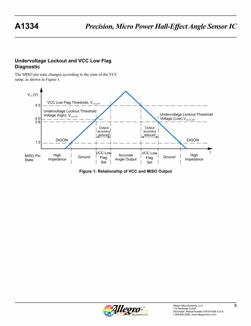
Undervoltage Lockout and VCC Low Flag DiagnosticThe MISO pin state changes according to the state of the VCC ramp, as shown in Figure 1.
V (V)CC
4.5
4.03.8
1.5
MISO PinState
t
VCC Low Flag Threshold, VUVLOTH
Undervoltage Lockout ThresholdVoltage (high), VUVLOHI
DIGON
HighImpedance
AccurateAngle Output
HighImpedance
Ground GroundVCC Low
Flag
Set
VCC Low
Flag
Set
Outputaccuracyreduced
DIGON
Undervoltage Lockout ThresholdVoltage (Low),VUVLOLOW
Outputaccuracyreduced
Figure 1: Relationship of VCC and MISO Output
Precision, Micro Power Hall-Effect Angle Sensor ICA1334
9Allegro MicroSystems, LLC115 Northeast CutoffWorcester, Massachusetts 01615-0036 U.S.A.1.508.853.5000; www.allegromicro.com
APPLICATION INFORMATION
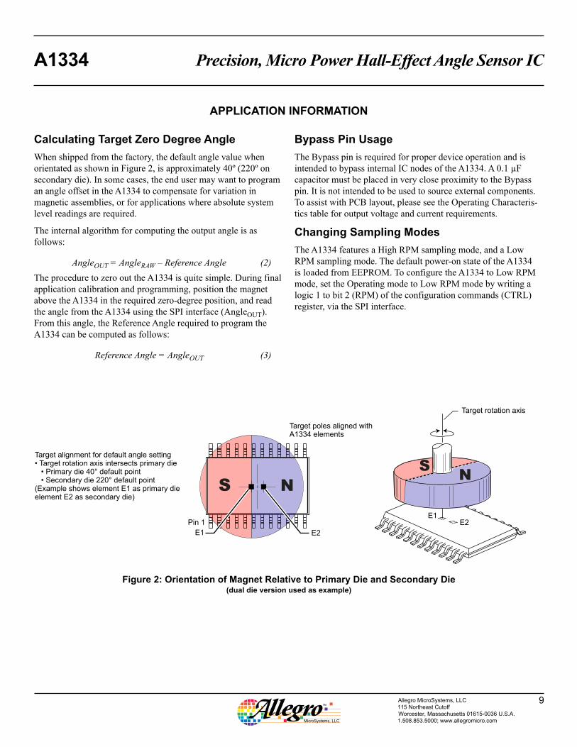
Figure 2: Orientation of Magnet Relative to Primary Die and Secondary Die(dual die version used as example)
NS
Target alignment for default angle setting• Target rotation axis intersects primary die
• Primary die 40° default point• Secondary die 220° default point
(Example shows element E1 as primary dieelement E2 as secondary die)
Target rotation axis
Target poles aligned withA1334 elements
E1
Pin 1E1
E2
E2
SN
Calculating Target Zero Degree AngleWhen shipped from the factory, the default angle value when orientated as shown in Figure 2, is approximately 40º (220º on secondary die). In some cases, the end user may want to program an angle offset in the A1334 to compensate for variation in magnetic assemblies, or for applications where absolute system level readings are required.
The internal algorithm for computing the output angle is as follows:
AngleOUT = AngleRAW – Reference Angle (2)The procedure to zero out the A1334 is quite simple. During final application calibration and programming, position the magnet above the A1334 in the required zero-degree position, and read the angle from the A1334 using the SPI interface (AngleOUT). From this angle, the Reference Angle required to program the A1334 can be computed as follows:
Reference Angle = AngleOUT (3)
Bypass Pin UsageThe Bypass pin is required for proper device operation and is intended to bypass internal IC nodes of the A1334. A 0.1 µF capacitor must be placed in very close proximity to the Bypass pin. It is not intended to be used to source external components. To assist with PCB layout, please see the Operating Characteris-tics table for output voltage and current requirements.
Changing Sampling ModesThe A1334 features a High RPM sampling mode, and a Low RPM sampling mode. The default power-on state of the A1334 is loaded from EEPROM. To configure the A1334 to Low RPM mode, set the Operating mode to Low RPM mode by writing a logic 1 to bit 2 (RPM) of the configuration commands (CTRL) register, via the SPI interface.
Precision, Micro Power Hall-Effect Angle Sensor ICA1334
10Allegro MicroSystems, LLC115 Northeast CutoffWorcester, Massachusetts 01615-0036 U.S.A.1.508.853.5000; www.allegromicro.com
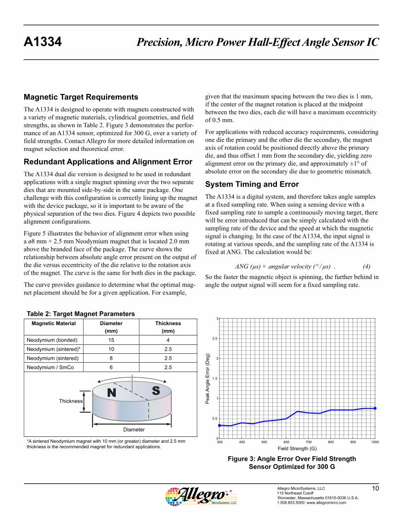
Magnetic Target RequirementsThe A1334 is designed to operate with magnets constructed with a variety of magnetic materials, cylindrical geometries, and field strengths, as shown in Table 2. Figure 3 demonstrates the perfor-mance of an A1334 sensor, optimized for 300 G, over a variety of field strengths. Contact Allegro for more detailed information on magnet selection and theoretical error.
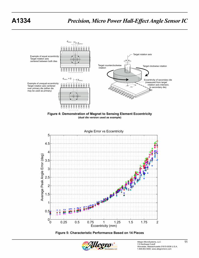
Redundant Applications and Alignment ErrorThe A1334 dual die version is designed to be used in redundant applications with a single magnet spinning over the two separate dies that are mounted side-by-side in the same package. One challenge with this configuration is correctly lining up the magnet with the device package, so it is important to be aware of the physical separation of the two dies. Figure 4 depicts two possible alignment configurations.
Figure 5 illustrates the behavior of alignment error when using a ø8 mm × 2.5 mm Neodymium magnet that is located 2.0 mm above the branded face of the package. The curve shows the relationship between absolute angle error present on the output of the die versus eccentricity of the die relative to the rotation axis of the magnet. The curve is the same for both dies in the package.
The curve provides guidance to determine what the optimal mag-net placement should be for a given application. For example,
given that the maximum spacing between the two dies is 1 mm, if the center of the magnet rotation is placed at the midpoint between the two dies, each die will have a maximum eccentricity of 0.5 mm.
For applications with reduced accuracy requirements, considering one die the primary and the other die the secondary, the magnet axis of rotation could be positioned directly above the primary die, and thus offset 1 mm from the secondary die, yielding zero alignment error on the primary die, and approximately ±1° of absolute error on the secondary die due to geometric mismatch.
System Timing and ErrorThe A1334 is a digital system, and therefore takes angle samples at a fixed sampling rate. When using a sensing device with a fixed sampling rate to sample a continuously moving target, there will be error introduced that can be simply calculated with the sampling rate of the device and the speed at which the magnetic signal is changing. In the case of the A1334, the input signal is rotating at various speeds, and the sampling rate of the A1334 is fixed at ANG. The calculation would be:
ANG (µs) × angular velocity ( ° / µs) . (4)So the faster the magnetic object is spinning, the further behind in angle the output signal will seem for a fixed sampling rate.
Table 2: Target Magnet ParametersMagnetic Material Diameter
(mm)Thickness
(mm)Neodymium (bonded) 15 4
Neodymium (sintered)* 10 2.5
Neodymium (sintered) 8 2.5
Neodymium / SmCo 6 2.5
N SThickness
Diameter
*A sintered Neodymium magnet with 10 mm (or greater) diameter and 2.5 mm thickness is the recommended magnet for redundant applications.
300 400 500 600 700 800 900 10000
0.5
1
1.5
2
2.5
3
Angle Error Over Field StrengthSensor Optimized for 300G
Pe
ak
An
gle
Err
or
(De
g)
Field Strength (G)
Figure 3: Angle Error Over Field StrengthSensor Optimized for 300 G
Precision, Micro Power Hall-Effect Angle Sensor ICA1334
11Allegro MicroSystems, LLC115 Northeast CutoffWorcester, Massachusetts 01615-0036 U.S.A.1.508.853.5000; www.allegromicro.com
Figure 5: Characteristic Performance Based on 14 Pieces
Figure 4: Demonstration of Magnet to Sensing Element Eccentricity(dual die version used as example)
Example of equal eccentricity:Target rotation axiscentered between both dies
Example of unequal eccentricity:Target rotation axis centeredover primary die (either diemay be used as primary)
Eccentricity of secondary die(measured from target
rotation axis intersect,to secondary die)
Target rotation axis
Target clockwise rotationTarget counterclockwiserotation
dAXIAL1dAXIAL2
d = 0AXIAL1 dAXIAL2
0 0.25 0.5 0.75 1 1.25 1.5 1.75 20
0.5
1
1.5
2
2.5
3
3.5
4
4.5
5
Eccentricity (mm)
Ave
rag
e P
ea
kA
ng
le E
rro
r (d
eg
)
Angle Error vs Eccentricity
Precision, Micro Power Hall-Effect Angle Sensor ICA1334
12Allegro MicroSystems, LLC115 Northeast CutoffWorcester, Massachusetts 01615-0036 U.S.A.1.508.853.5000; www.allegromicro.com
VCC
A1334(Dual DieVersion)
VCC_1
SCLK_1
SCLK_2
MISO_1
MOSI_1
MOSI_2
MISO_2
BIAS_1
BYP_1 VCC_2
AGND_1 AGND_2
BYP_2
DGND_1 DGND_2
0.1 µF
100 Ω 100 Ω
0.1 µF 0.1 µF
HostMicroprocessor
CS_1
CS_2
TargetMagnet
BIAS_2
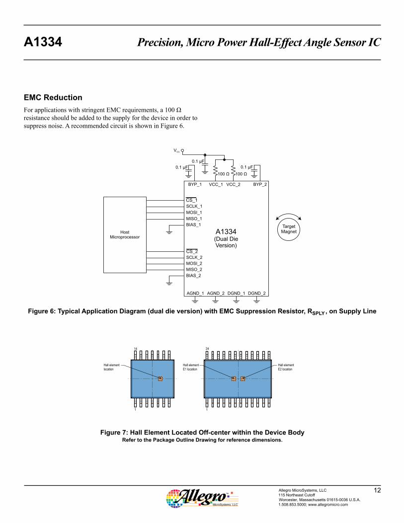
Figure 6: Typical Application Diagram (dual die version) with EMC Suppression Resistor, RSPLY , on Supply Line
EMC ReductionFor applications with stringent EMC requirements, a 100 Ω resistance should be added to the supply for the device in order to suppress noise. A recommended circuit is shown in Figure 6.
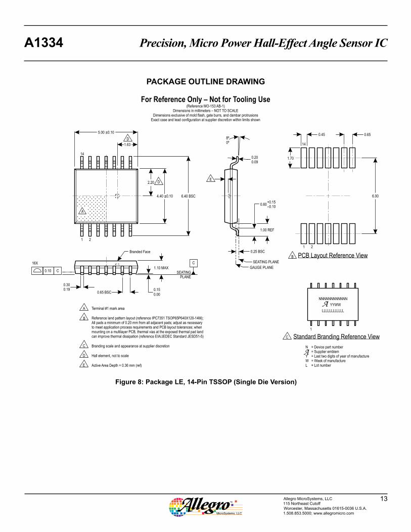
Figure 7: Hall Element Located Off-center within the Device BodyRefer to the Package Outline Drawing for reference dimensions.
1
Hall elementE1 location
Hall elementE2 location
Hall elementlocation
24
1
14
Precision, Micro Power Hall-Effect Angle Sensor ICA1334
13Allegro MicroSystems, LLC115 Northeast CutoffWorcester, Massachusetts 01615-0036 U.S.A.1.508.853.5000; www.allegromicro.com
For Reference Only – Not for Tooling Use(Reference MO-153 AB-1)
Dimensions in millimeters – NOT TO SCALEDimensions exclusive of mold flash, gate burrs, and dambar protrusions
Exact case and lead configuration at supplier discretion within limits shown
A
1.10 MAX
0.15
0.00
0.300.19
0.200.09
8º0º
0.60
1.00 REF
C
SEATINGPLANE
C0.10
16X
0.65 BSC
0.25 BSC
21
14
5.00 ±0.10
4.40 ±0.10
2.20
1.63
6.40 BSC
GAUGE PLANE
SEATING PLANE
A
B
B
DE
D
Branding scale and appearance at supplier discretion
Hall element, not to scale
Active Area Depth = 0.36 mm (ref)
C
D
E
6.00
0.650.45
1.70
14
21
1
C
Branded FacePCB Layout Reference View
Standard Branding Reference View
= Device part number= Supplier emblem= Last two digits of year of manufacture= Week of manufacture= Lot number
N
YWL
Terminal #1 mark area
Reference land pattern layout (reference IPC7351 TSOP65P640X120-14M);All pads a minimum of 0.20 mm from all adjacent pads; adjust as necessaryto meet application process requirements and PCB layout tolerances; whenmounting on a multilayer PCB, thermal vias at the exposed thermal pad landcan improve thermal dissipation (reference EIA/JEDEC Standard JESD51-5)
NNNNNNNNNNNN
YYWW
LLLLLLLLLLLL
+0.15–0.10
Figure 8: Package LE, 14-Pin TSSOP (Single Die Version)
PACKAGE OUTLINE DRAWING
Precision, Micro Power Hall-Effect Angle Sensor ICA1334
14Allegro MicroSystems, LLC115 Northeast CutoffWorcester, Massachusetts 01615-0036 U.S.A.1.508.853.5000; www.allegromicro.com
For Reference Only – Not for Tooling Use(Reference MO-153 AD)
Dimensions in millimeters – NOT TO SCALEDimensions exclusive of mold flash, gate burrs, and dambar protrusions
Exact case and lead configuration at supplier discretion within limits shown
A
1.10 MAX
0.150.05
0.300.19
0.200.09
+0.15–0.10
8º0º
0.60
1.00 REF
C
SEATINGPLANE
C0.10
24X
0.65 BSC
0.25 BSC
2
2
1
1
24
24
7.80 ±0.10
4.40 ±0.10
2.20
6.40 BSC
GAUGE PLANE
SEATING PLANE
A
B
B
0.65
6.10
1.65
0.45
D
D
D
D
D D
Hall elements (E1, E2), corresponding to respective die; not to scale
1.003.40
E1 E2
C Branding scale and appearance at supplier discretion
E
E
C
PCB Layout Reference View
Terminal #1 mark area
Reference land pattern layout (reference IPC7351 TSOP65P640X120-25M);all pads a minimum of 0.20 mm from all adjacent pads; adjust as necessaryto meet application process requirements and PCB layout tolerances; whenmounting on a multilayer PCB, thermal vias can improve thermal dissipation(reference EIA/JEDEC Standard JESD51-5)
Active Area Depth 0.36 mm REF
1
Standard Branding Reference View= Device part number= Supplier emblem= Last two digits of year of manufacture= Week of manufacture= Lot number
N
YWL
NNNNNNNNNNYYWW
LLLLLLLLLL
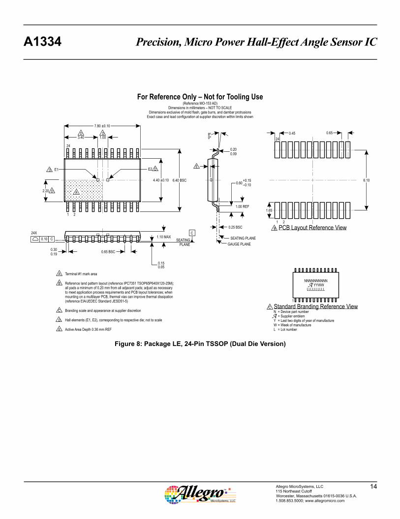
Figure 8: Package LE, 24-Pin TSSOP (Dual Die Version)

Precision, Micro Power Hall-Effect Angle Sensor ICA1334
15Allegro MicroSystems, LLC115 Northeast CutoffWorcester, Massachusetts 01615-0036 U.S.A.1.508.853.5000; www.allegromicro.com
Copyright ©2010-2014, Allegro MicroSystems, LLCAllegro MicroSystems, LLC reserves the right to make, from time to time, such departures from the detail specifications as may be required to
permit improvements in the performance, reliability, or manufacturability of its products. Before placing an order, the user is cautioned to verify that the information being relied upon is current.
Allegro’s products are not to be used in any devices or systems, including but not limited to life support devices or systems, in which a failure of Allegro’s product can reasonably be expected to cause bodily harm.
The information included herein is believed to be accurate and reliable. However, Allegro MicroSystems, LLC assumes no responsibility for its use; nor for any infringement of patents or other rights of third parties which may result from its use.
Revision HistoryRevision Date Description
– September 23, 2014 Initial Release
For the latest version of this document, visit our website:
www.allegromicro.com