PRECISION GRINDING - technitoolinc.com
25
PRECISION GRINDING PRODUCT CATALOGUE
Transcript of PRECISION GRINDING - technitoolinc.com

PRECISION GRINDINGPRODUCT CATALOGUE

Professional excellenceWe strive for the highest quality in our products and our service.
Strategic partnershipsWe work diligently to make our customers, our suppliers, and our employees our "strategic partners".
Integrity and fairnessWe are transparent and reliable in our interactions with all our business partners.
Creative innovationWe harness technological leadership, individual and company initiatives, and the will to change, to keep the organization moving forward.
Our Values

1
Contents
Company Profile 2-4
About the Catalogue 5
Wheel Specifications 6-8
Selecting Grinding Wheels 9
Standard Types and Shapes of Abrasive Wheels 10-11
Standard Profiles 11
Safety Guide for the Use of Abrasive Wheels 12-13
Aerospace & Gas Turbine 14
Thread Grinding 15
Gears 16-17
Bearings 18
Automotive 19
Natural and Synthetic Rubber 20
Diamond and CBN Dressing 21
Surface Grinding 22-23
Cylindrical Grinding 24
Centerless Grinding 25
High Speed Steel (HSS) 26
Tool Room Grinding 27-29
Internal Grinding 29
Surface Grinding Segments 30-32
Sharpening Stones 33
Bench & Pedestal 34-35
Speed Conversion Table 36-37
Grain Size Conversion Table 38
Minimum Quantities for Production of Vitrified Abrasive Products 38
Inch/Millimeter Conversion Table 39
Cutting and Grinding Discs 40
VB
-00
02-0
4-2
0-0
7

2 | Precision Grinding
Company Profile
CGW Company ProfileFor more than 60 years, CGW - Camel Grinding Wheels - Israel's only abrasives manufacturer, has been the first choice in grinding and cutting products for both locally and internationally.CGW’s ceramic (vitrified) bond and organic (resinoid) bond products are available in more than 75 countries throughout North and South America, Europe, Africa, Asia and Australia, in locations from small machine shops to advanced manufacturing centers. In North America, our subsidiary in Chicago,IL, CGW-USA, maintains a large warehouse and manufacturing facility, and our converter of coated abrasives is located in Los Angeles.We take pride in developing and producing high-quality, high-performance products to meet the technological challenges of grinding conventional metals and today’s sophisticated alloys.CGW products are manufactured under strict quality control. CGW is certified by the highest industrial standards: EN 12413, EN 13743, ANSI B7.1, ISO 18001, ISO 14001 and OSA.

4 | Precision Grinding 5
About the Catalogue
We are pleased to present our complete catalogue of standard vitrified bonded abrasive products.The technical guide at the beginning of the catalogue contains detailed explanations on a number of subjects, including types of abrasive grains, bonds, and structures. Each section shows initial recommendations for choosing the most suitable specifications for various applications.
Leading corporations in over 75 countries around the world choose CGW brand because of the company’s quality and cost-effective products. CGW’s application engineers provide fast and effective technical support to customers with innovative technology which sets CGW apart from other abrasives manufacturers.
CGW specializes in the production of grinding wheels for various industries:
• Aerospace
• Land-based turbine
• Gear grinding
CGW products are manufactured under strict quality control. We are committed to achieve and maintain a comprehensive Quality & Environmental Management System compliant with and certified to the highest industrial standards including EN 12413, EN 13743, ANSI B7.1, ISO 18001, ISO 14001, OSA and EAC.
An Industry Leader in Abrasive Products
CGW manufactures thousands of products for use in the aerospace, automotive, gas turbine, oil rig, construction and other industries.
Our broad range of products includes wheels for surface grinding | centerless grinding | cylindrical grinding | off-hand grinding | creep-feed grinding
Our attention to details and commitment to excellence is reflected in our products whichhave earned a worldwide reputation for high quality, consistency and cost-effectiveness.
CGW’s 5-Point Manufacturing & Operating Philosophy
1
3
2
4
5
Advanced in-house development and production
Ongoing, stringent quality control
Efficient planning and scheduling
On-time, error-free shipments
"The best service in the world"
Our in-house R&D and engineering teams, supported by laboratories and testing facilities, allow us to continually improve the existing products and develop high-precision solutions to meet customers needs.
The manufacturing processes and maintenance of our production facilities comply with strict international quality, safety and environmental standards.
Our streamlined system of coordinating between the sales and production departments allows a quick turnaround and a fast response to unexpected schedule changes.
We work diligently to prevent delays in shipment from the time an order is placed until it is shipped.
Our industry leadership is based on decades of commitment to exceptional customer service. Through this unconditional dedication, we have forged long-standing partnerships with customers throughout the world.

6 | Precision Grinding 7
The CGW grinding wheels are made of abrasive grains held together by a bond. The innumerable grinding characteristics are successfully achieved by varying the type of bond and the structure of the wheel.
Abrasive Grain
There are two main categories of grain:
Aluminium Oxide for grinding material of high tensile strength, such as alloy steel, high-speed steels.
Silicon Carbide for grinding low-tensile steels, cast iron, carbides, and non-ferrous metals.
CGW Grain Types
A - Brown Aluminium Oxide - The most common of all grains, for heavy-duty generalpurpose work.
BAS - High performance Aluminium Oxide - Blue Fired Aluminium Oxide, specially made for centerless grinding.
WA - White Aluminium Oxide - White Aluminium Oxide, the high friability of this grain enables fast and cool cutting. Suitable for light grinding of steels of all kinds, particularly tool steel.
WAB - White Aluminium Oxide+Blue Bond - Particularly suited for grinding HSS over 55 RC. Provides exceptionally cool, fast cutting action. Requires minimum dressing. Also available in WAR.
WAR - Aluminium Oxide+Red Bond - Particularly suited for grinding HSS over 55 RC. Provides exceptionally cool, fast cutting action. Requires minimum dressing. Also available in WAR.
WAY - White Aluminium Oxide+Yellow Bond - Are primarily used in wheels that require a very open structure. For creep-feed grinding with continuous dressing.
WAG - White Aluminium Oxide+Special Bond I - Are primarily used in wheels with a
very open structure. Excellent for creepfeed grinding with non-continuous dressing.
WAP - White Aluminium Oxide+Special Bond II - for special wheels with cutting speed of 80 M/S. Designed to perform light, fast passes over the blade or other workpiece.
WAL - Special grain and bond for improved surface integrity - Special wheel designed for creep-feed grinding. Contains a unique combination of special grain and bond which enables the improved form holding and longer life span. The wheel is characterized by interconnected pores, allowing maximum cooling action and stock removal.
WALB - Eliminates visible burn. Ensures no white layer. Reduces wheel consumption.
PA - Pink Aluminium Oxide - A tough but friable grain for general-purpose wheel. Excellent on large surface areas.
RA - Ruby Aluminium Oxide - harder than PA and WAB, this grain is good for use on highchromium steel.
AS1 - 10% Ceramic Aluminium Oxide - Ceramic Aluminium Oxide, a ceramic grain, blended with white aluminium oxide, creates a wheel with maximum grinding performance, excellent for form holding and cool cut. Available in AS1, AS2, AS3, AS5.
AS2 - 20% Ceramic Aluminium Oxide - Ceramic Aluminium Oxide, a ceramic grain, blended with white aluminium oxide, creates a wheel with maximum grinding performance, excellent for form holding and cool cut. Available in AS1, AS2, AS3, AS5.
AS3 - 30% Ceramic Aluminium OxideI - Ceramic Aluminium Oxide, a ceramic grain, blended with white aluminium oxide, creates a wheel with maximum grinding performance, excellent for form holding and cool cut. Available in AS1, AS2, AS3, AS5.
Technical Information
Technical Information
Wheel Specifications
Abrasive
A Brown Aluminium Oxide
BAS High performance Aluminium Oxide
WA White Aluminium Oxide
WAB White Aluminium Oxide+Blue Bond
WAR White Aluminium Oxide+Red Bond
WAY White Aluminium Oxide+Yellow Bond
WAG White Aluminium Oxide+Special Bond I
WAP White Aluminium Oxide+Special Bond II
WALSpecial grain and bond for improved surface integrity
PA Pink Aluminium Oxide
RA Ruby Aluminium Oxide
AS1 10% Ceramic Aluminium Oxide
AS2 20% Ceramic Aluminium Oxide
AS3 30% Ceramic Aluminium Oxide
AS5 50% Ceramic Aluminium Oxide
DA White and Brown Aluminium Oxide
SA Semi-friable Aluminium Oxide
HA Monocrystal Aluminium Oxide
KA Bubble alumina
GC Green Silicon Carbide
C Black Silicon Carbide
Grain Size
Coarse 24, 30, 36
Medium 46, 54, 60
Fine 80, 100, 120, 150
Very Fine 180, 220, 240
Grade
Soft B, C, D, E, F, G, H
Medium I, J, K, L
Hard M, N, O, P, Q
Structure
Medium/Standard Open/Porous
6 7 8 9 | 10 11 12 13 14 15
Bond
V Vitrified
B Resinoid
BF Reinforced Resinoid
Wheel Dimensions
External Diameter up to 635mm / 25"
Width up to 500mm / 20"
Internal diameter (bore) up to 406mm / 16"
Bore
Width
Diameter
177x25.4x31.75
Maximum safe operating speed
OSA certified & European safety
standard
Wheel dimensions
Batch no.
EAN no.
Abrasive
Grain size
Grade
Structure
Bond
WA 80 K 7 V
Wheel specification

8 | Precision Grinding 9
Structures 6-9:medium/standard
Structures 10-15:open/porous
Hardness-Structure Diagram
GradeClosed Structure Open
5 6 7 8 9 10 11
Soft H H5 H6 H7 H8 H9 H10 H11
I I5 I6 I7 I8 I9 I10 I11
J J5 J6 J7 J8 J9 J10 J11
K K5 K6 K7 K8 K9 K10 K11
L L5 L6 L7 L8 L9 L10 L11
Hard M M5 M6 M7 M8 M9 M10 M11
1 inch
25.4mm
1mm ≈ = = grit 24 MESH
25.424
Technical Information
Technical Information
Grain Size
The grain size is the physical size of the abrasive grains used in making a wheel. It relates to the number of meshes per linear inch of the screen in which the grains will pass through when they are graded. The higher the numbers of grain, the smaller openings in the screen the grains pass. There are four different groups of the grain size - coarse, medium, fine and very fine. A larger grain size allows fast cutting on a poor surface quality finish. Ultra-fine grain sizes are for fine finishes.
Grade (Hardness)
The grade of a grinding wheel refers to the strength of the bond to hold the abrasive grains together. The range of grade is represented in alphabetical form - A (soft) to Z (hard). The higher the letter the stronger the bond. A soft grain wheel tends to release grains quickly to expose new, sharper grains where hard wheels retain the abrasive grains longer.
Structure
Wheel structure refers to the spacing between grain particles within the bond and is measured in terms of the volume content of the abrasive in the wheel. In open structure wheel, the grains are relatively far apart, in close structure, the pores are small and the grains are close together.
Bond
The function of the bond is to hold the abrasive grains together. Most commonly used are the vitrified and resinoid bonds.
Vitrified Bond are the various clays or ceramics used to form bonds, allowing a wide range of structures with special properties and grinding characteristics. Their strength is developed by firing in kilns to temperatures of up to 1,000°C. The vitrified-bonded wheels are excellent for precision grinding and fast stock removal due to their rigidity and friability.
Selecting Grinding Wheels
Workpiece
Type and hardness of the material: the harder the material, the softer the grade of the wheel required.
Aluminium Oxide: most efficient for grinding high-tensile materials such as steel and ferrous castings. The more friable types of alumina are preferred for use on harder steels.
Silicon Carbide: for materials with low tensile strength, carbides, and non-ferrous metals.
Stock removal
The stock removal rate depends on the grain size of the abrasive material and bond type:
• A coarse grit (24-46 MESH) is suitable for high stock removal rates.
• Fine grits are best for fine finishes and tight tolerances.
Surface finish
High surface finish is achieved by using a fine grit. High quality surface finish results require using a dense or close structure wheel.
Grinding machine
• The power available defines the rate of stock removal. The greater the power available, the harder the grade of wheel required for efficient operation.
• Deterioration in machine condition leads to vibration and early breakdown of the wheel.
Grinding fluids
• Grinding fluids provide cooling and/or lubrication. A proper use is an important factor in achieving satisfactory results.
• Coolants and lubricants are capable of reducing heat formation. The relative importance of cooling vs. lubrication determines whether a water-based coolant or an oil-based lubricant is used. Coolants are usually able to transfer the heat away from the workpiece, but are unable to prevent the development of heat.
• In dry grinding, the temperature at the grinding point is not much higher than in wet grinding, but the rate of heat formation is much higher.
Factors to be considered when selecting a grinding wheel:
For maximum efficiency in grinding operation, it is essential to have the right wheel for the job.

10 | Precision Grinding 11
Technical Information
Technical Information
Standard Types and Shapes of Abrasive Wheels (cont.)
Standard Profiles
23 DxT/NxH-PxF
38 D/JxT/UxH
24 DxT/NxH-PxF
27 DxUxH
39 D/JxT/UxH
25 DxT/NxH-PxF
35 DxTxH-W
43 DxUxH
26 DxT/NxH-PxF
DxT/NxH-PxF/Gor if recesses are not the same size: attached to plate
DxT/NxH-PxF/Gor if recesses are not the same size:
1 DxTxH 3 D/JxT/UxH
5 DxTxH-PxF
7 DxTxH-PxF
DxTxH-PxF/Gor if recesses are not the same size:
12 D/JxT/UxH
21 D/KxT/NxH
9 DxTxH-PxF R..
13 D/JxT/UxH
21A D/KxT/NxH
11 D/JxTxH-W..E..
20 D/KxT/NxH
22 D/KxT/NxH-PxF
2 DxTxW
4 D/JxT/UxH 6 DxTxH-W..E..
Standard Types and Shapes of Abrasive Wheels
D Outer diameter
E Thickness around bore
F Depth of recess
G Depth of second recess
H Diameter of bore
J Diameter of flat outer surface
K Diameter of flat inner surface
L Length of segment or abrasive wheel
N Depth of release on one side
O Depth of release on other side
P Diameter of recess
R Radius
T Thickness (general)
U Thickness of edge
V Angle of profiles
V1 Second angle of (profiles)
W Width of wall
Types and profiles of CGW abrasives are marked in accordance with international standards.

12 | Precision Grinding 13
Do Don't
Tap at these points
Place large and heavy wheels on a clean, hard surface
Always handle and store wheels in a careful manner.
Before mounting, visually inspect and ring test all wheels for possible damage (ILL. 1 and 2).
Check machine speed against the maximum safe operating speed marked on the wheel.
Check mounting flanges for equal and correct diameter (ILL. 3).
Use mounting blotters when supplied with wheels (ILL. 3).
Be sure work rest is properly adjusted: leveled with or above the center of wheel; no more than 1/8” away from wheel (ILL. 4).
Always use a safety guard covering at least one-half of the grinding wheel (ILL. 4).
Allow newly-mounted wheels to run at operating speed, with guard in place, for at least one minute before grinding.
Always wear safety glasses or any type of eye protection when grinding.
Be sure to employ dust controls and/or protective measures appropriate to the material being ground.
When shutting down a wet grinding operation, the fluid must be first shut off and allowing the wheel to rotate until the coolant has been spun out.
•
•
•
•
•
•
•
•
•
•
•
Don’t use a cracked wheel or one that has been dropped or damaged.
Don’t force a wheel onto the machine or alter the size of the mounting hole.
Don’t alter the shape of the wheel in any way.
Never exceed the maximum operating speed marked on wheel.
Don’t use mounting flanges on which the bearing surfaces are not clean, flat and free of burrs.
Don’t tighten the mounting nut excessively.
Don’t stand or allow another person to stand directly in front of or in line with a grinding wheel when the grinding machine is started.
Don’t grind on the side of the wheel (see safety code for exception).
Don’t start the machine until the wheel guard is in place.
Don’t forcefully jam the workpiece into the wheel.
Don’t force grinding so that the machine noticeably slows down or the workpiece becomes overheated.
dust hood recommended in addition to goggles
distance from wheelno more than 2 mm
work rest aligned with or slightly higher than spindle
angle of guard opening max. 650
flangeflange
tightening nut
threading 3-5mm longer than needed
space between flange and wheel
soft blotters between the wheel and the flange (both sides)
Tap at these points
Safety G
uide
Safety G
uide
Safety Guide for the Use of Abrasive Wheels
Bonded abrasive products are fragile and must be handled with utmost care. Follow these safety rules to prevent injury.
X
A visible difference between the sharp, clean tone produced by an intact abrasive wheel, and the dull tone producd by a cracked wheel, makes it possible to further examine the wheel, in addition to visual inspection, by performing a ring test on it before mounting (ILL. 1 and 2).
Ring Test
1) Ring testing small wheels
3) Mounting
2) Ring testing large wheels
4) Guard, work rest and dust hood
•
•
•
•
•
•
•
•
•
•
•

14 | Precision Grinding 15
Aerospace &
Gas Turbine
Wheels for the Aerospace & Gas Turbine Industries
Wheels for grinding blades & vanes
The Innovative vitrified technology for grinding blades and vanes by CGW are especially designed for the aerospace industry. The wheels are made with CGW special new bond for creep feed grinding applications using either continuous or non-continuous dressing. The open structure wheels allow cool grinding and are able to achieve the delicate balance between self-sharpening and form holding.
• Cool grinding
• Excellent form holding
• Continuous dressing
Wheels for grinding gas turbine blades
CGW open structure creep feed grinding wheels are Ideally suited for high efficiency production of gas turbine blades.
Blades and vanes can be found in their hundreds in just one turbine - in the compressor stage, the combustion stage, and the turbine stage. CGW's advanced technology of soft grinding wheel provides an excellent burn prevention in sensitive inconel parts, espceially in large turbine blades.
• Cool grinding
• Excellent form holding
• High output of blades per wheel
Thread Grinding
Superior corner holding with high material removal rates
CGW new generation of thread grinding wheels offers cool cutting with excellent form holding to meet the strict tolerance required by the industry.Based on the high-performance AZ grain and special designed bond, CGW thread wheels are made to optimize the grinding process of hard material and to achieve high surface reequipments.• Up to 80 m/s wheel speed
Wheels for Thread Grinding

16 | Precision Grinding 17
The latest generation of high-performance ceramic abrasives composition developed by CGW for the Worm Grinding application. The open-structure, highly homogenous wheel reduces temperature allowing cooler operation, without burning the wheel and work-piece
• Operating speed up to 80 M/S
• Reduced grinding cycle time
• Cool grinding capability
Wheels for Gear GrindingMulti-rib "Warm" Pofile Wheel
CGW Gear Grinding wheels are available in a wide
variety of sizes and grains
• Standard or ceramic grain
• Open or close structure wheel
• For all standard bore sizes
• Up to 635mm diameter size
• For all required thickness for Gear Grinding
Gear G
rinding
Gear G
rinding
Type 1
D =Diameter | T=Thickness | H=Bore
Type 4
D=Diameter | T=Thickness | H=Bore U=Rim thickness | J=Flat surface diameter
Single Rib Gear Grinding Wheel
The Innovative technology by CGW using high-performance ceramic abrasives with the new developed bonding system was especially designed for the Single Rib Grinding application. The Single Rib Gear Grinding uses a flexible technique where each tooth flank is ground individually. The open-structure wheel ensures maximum safety against burning:
• Operating speed up to 50 M/S
• High stock removal rate
• Excellent in form holding
A new designed product representing a special grain combination that result in an excellent shape holding with good self-sharpening, enabling the maximum stock removal rate.
Standard Wheel Types:
18 | Precision Grinding 19
Autom
otive
19
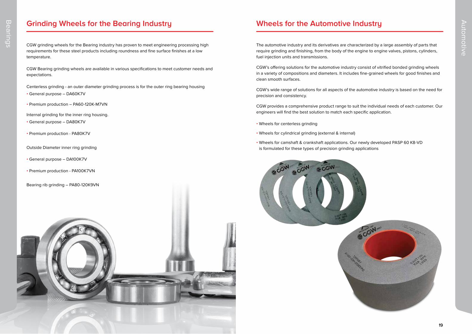
Grinding Wheels for the Bearing Industry
CGW grinding wheels for the Bearing industry has proven to meet engineering processing high requirements for these steel products including roundness and fine surface finishes at a low temperature.
CGW Bearing grinding wheels are available in various specifications to meet customer needs and expectations.
Centerless grinding - an outer diameter grinding process is for the outer ring bearing housing
• General purpose – DA60K7V
• Premium production – PA60-120K-M7VN
Internal grinding for the inner ring housing.
• General purpose – DA80K7V
• Premium production - PA80K7V
Outside Diameter inner ring grinding
• General purpose – DA100K7V
• Premium production - PA100K7VN
Bearing rib grinding – PA80-120K9VN
Wheels for the Automotive Industry
The automotive industry and its derivatives are characterized by a large assembly of parts that require grinding and finishing, from the body of the engine to engine valves, pistons, cylinders, fuel injection units and transmissions.
CGW’s offering solutions for the automotive industry consist of vitrified bonded grinding wheels in a variety of compositions and diameters. It includes fine-grained wheels for good finishes and clean smooth surfaces.
CGW's wide range of solutions for all aspects of the automotive industry is based on the need for precision and consistency.
CGW provides a comprehensive product range to suit the individual needs of each customer. Our engineers will find the best solution to match each specific application.
• Wheels for centerless grinding
• Wheels for cylindrical grinding (external & internal)
• Wheels for camshaft & crankshaft applications. Our newly developed PASP 60 K8-VD is formulated for these types of precision grinding applications
Bearings

20 | Precision Grinding 21
Wheels for Grinding Natural and Synthetic Rubber
Wheels for Turbine blade root form
CGW KA wheels are especially designed for grinding
natural and synthetic rubber including polyurethane,
ebonite, silicone, and other soft materials
A new development of CGW technical department,
using innovative materials at high grade purity
Application:
Particularly suitable for the grinding of coated rollers for
the paper, timber and textile industries
Features and Benefits:
Excellent cost-benefit ratio in comparison to traditional
silicon carbide wheels
extra low weight Provide grinding without vibration
marks
High induced porosity to ensure grinding in low
temperature
No diamond tools for dressing is required
Available specifications:
• KA 2-1 fine: for excellent finish, suitable especially for
slots face grinding
• KA 3-2 medium: to achieve high stock removal rate
and good surface finish
• KA 5-3 coarse: for extra high removal rates.
Diameters: from 100 mm (4 ") to 600 mm (24")
Natural and Synthetic R
ubber
Wheels for Diamond and CBN Dressing
Diam
ond and CB
N D
ressing
for EWAG machines
for WENDT machines
for A
GATHON machines
for H
AAS machines
for
WEN
DT
m
achines
fo
r ROLLOMATIC machines
for ANCA machines

22 | Precision Grinding 23
Diameter (D) Recess Dimensions (P) Thickness (T) Bore (H)
Inches mm Inches mm Inches mm Inches mm
6 150 - - 1/4 | 1/2 6.3 | 12.7 11/4 31.75
7 177 - - 1/4 | 3/8 | 1/2 6.3 | 10 | 12.7 11/4 31.75
8 203.2 - - ¼ | ½ 6.3 | 12.7 11/4 31.75
10 250 - - ¾ | 1 19 | 25.4 2 | 3 | 5 50.8 | 76.2 | 127
12 305 - - 1 25.4 3 | 5 76.2 | 127
14 356 - - 1 | 11/2 25.4 | 38 3 | 5 76.2 | 127
16 406 - - 11/2 | 2 | 21/2 38 | 51 | 63 5 127
20 508 - -1 | 11/2 | 24 | 6 | 8
25.4 | 38 | 51 102 | 150 | 203
5 | 8 | 10127 | 203.2
254
7 177 3x1/4 78x6.3 ¾ 19 1¼ 31.75
7 177 3x1/2 78x12.7 1 25.4 11/4 31.75
8 203.2 3x1/2 78x12.7 ¾ 19 11/4 31.75
8 203.2 3x1/2 78x12.7 1 25.4 11/4 31.75
12 305 71/2x1/2 190x12.7 11/2 | 2 38 | 51 3, 5 76.2 | 127
14 356 8x1/2 200x12.7 11/2 38 5 127
14 356 8x1 200x25.4 2 51 5 127
20 508 by request by request1 | 11/2 | 24 | 6 | 8
25.4 | 38 | 51 102 | 150 | 203
5 | 8 | 10127 | 203.2
254
12 305 71/2x1/2 190x12.7 2 51 3 | 5 76.2 | 127
14 356 8x3/8 200x10 2 51 5 127
18 455 111/2x1/2 290x12.7 2 51 8 203.2
20 508 by request by request1 | 11/2 | 24 | 6 | 8
25.4 | 38 | 51 102 | 150 | 203
5 | 8 | 10 | 12127 | 203.2 254 | 304.8
Surface Grinding Wheels
Surface G
rinding
Surface G
rinding
The edge of the wheel is in contact with the workpiece.
Horizontal Surface Grinding Standard Dimensions:
35 M/S
Horizontal SurfaceGrinder
Type 1 (straight wheel)
D =Diameter | T=Thickness | H=Bore
Type 5 (recess one side) Type 7 (recess two sides)
D =Diameter | T=Thickness | H=Bore P =Diameter of recess | F=Depth of recess E=Thickness around bore
D =Diameter | T=Thickness | H=Bore P =Diameter of recess | F=Depth of recess E=Thickness around bore
Typ
e 1
Typ
e 5
Typ
e 7
Recommended Specifications:
General Purpose WA46H8V
Steel < 55Hrc WA46K7V
Steel > 55Hrc AS46H8V
Stainless Steel (soft) 300 series
PA46J8V
Stainless Steel(hard) 400 series
AZ46H8V
Nickel Alloys WAG60F15V
HSS & Tool Steel AS360I13V
Carbides / Tungsten GC60J7V
Non-ferrous Metals GC60J7V
WAThe most friable grain -easy cutting action
WAB (AZ)
Fast and cool cutting
PA Tough but friable
RATougher than PA -good for chromium steel
WAGExcellent form holding -cool grinding
GCFor carbide and non-ferrous applications
AS
Submicron crystal structure gives long life with maximum performance

24 | Precision Grinding 25
Centerless G
rinding
Centerless Grinding
In centerless grinding, the workpiece is held between two wheels - the grinding wheel and the feed-regulating wheel. CGW’s centerless grinding solutions give a precision fine finish while maintaining accuracy and control over the process.
Standard Dimensions:
Recommended Specifications:
General Purpose BAS60K7V
Steel < 55Hrc BAS60M7V
Steel > 55Hrc BAS60L7V
Stainless Steel (soft) 300 series BAS60M7V
Stainless Steel (hard) 400 series BAS60K7V
Nickel Alloys BAS60K7V
HSS & Tool Steel BAS60K7V
Carbides / Tungsten GC60J7V
BASImproved aluminium oxide grain, specially prepared for centerless grinding
Diameter Thickness Bore
Inches mm Inches mm Inches mm
12 305 3 - 5 76 - 127 5 127
14 356 3 - 5 76 - 127 5 127
16 406 3 - 8 76 - 203 5 | 8 | 10 127 | 203.2 | 254
20 508 3 - 10 76 - 250 12 304.8
24 610 3 | 4 | 6 | 8 | 10 76 - 250 12 304.8
CenterlessGrinder
Cylindrical G
rinding
Cylindrical Grinding
A cylindrical part rotates while a wheel grinds along its length.
Type 1
D =Diameter | T=Thickness | H=BoreCylindricalGrinder
Standard Dimensions:
Diameter Thickness Hole
Inches mm Inches mm Inches mm
12 305 1 | 11/2 | 2 25.4 | 38 | 51 3 | 4 | 5 76 | 101.6 | 127
14 356 1 | 11/2 | 2 | 3 25.4 | 38 | 51 | 76 3 | 4 | 5 76 | 101.6 | 127
16 406 1 | 11/2 | 2 | 3 25.4 | 38 | 51 | 76 5 | 8 127 | 203.2
18 455 1 | 11/2 | 2 | 3 25.4 | 38 | 51 | 76 5 | 8 127 | 203.2
20 508 1 | 11/2 | 2 | 3 | 4 25.4 | 38 | 51 | 76 | 102 5 | 8 | 12 127 | 203.2 | 304.8
24 610 1 | 11/2 | 2 | 3 | 4 25.4 | 38 | 51 | 76 | 102 8 | 12 203.2 | 304.8
Recommended Specifications:
General Purpose SA60K7V
Steel < 55Hrc PA60M7V
Steel > 55Hrc SA60K7V
Stainless Steel (soft) 300 series SA60M7V Stainless Steel (hard) 400series
SA60K7V
Nickel Alloys WAG80H8V
HSS & tool steel SA60K7V
Carbides / Tungsten GC60J7V
New designed composition PA/WAB 120 F11V
SA Semi-friable aluminium oxide
WAG Highly friable grain
PA Tough but friable aluminium oxide
GC For non-ferrous metals

26 | Precision Grinding 27
High S
peed Steel (HS
S)
Tool Room
Grinding
35 M/S
Type 1 (straight wheel)
D =Diameter | T=Thickness | H=Bore
Type 5 (recess one side) Type 7 (recess two sides)
D =Diameter | T=Thickness | H=Bore P =Diameter of recess | F=Depth of recess E=Thickness around bore
D =Diameter | T=Thickness | H=Bore P =Diameter of recess | F=Depth of recess E=Thickness around bore
Standard Dimensions:
Diameter (D) Recess Dimensions (P) Thickness (T) Bore (H)
Inches mm Inches mm Inches mm Inches mm
6 150 1/4 | 1/2 6.3 | 12.7 11/4 31.75
7 177 1/4 | 3/8 | 1/2 6.3 | 10 | 12.7 11/4 31.75
8 203.2 1/4 | 1/2 6.3 | 12.7 11/4 31.75
10 254 3/4 | 1 19.05 | 25.4 2 | 3 | 5 50.8 | 76.2 | 127
12 305 1 25.4 3 | 5 76.2 | 127
14 356 1 | 11/2 25.4 | 38 3 | 5 76.2 | 127
7 177 r/1/s3x1/4 r/1/s76.2x6.3 3/4 19.05 11/4 31.75
7 177 r/1/s3x1/2 r/1/s76.2x12.7 1 25.4 11/4 31.75
8 203.2 r/1/s3x1/4 r/1/s76.2x6.3 3/4 19.05 11/4 31.75
8 203.2 r/1/s3x1/2 r/1/s76.2x12.7 1 25.4 11/4 31.75
12 305 r/1/s71/2x1/2 r/1/s190x12.7 11/2 | 2 38 | 50.8 3 | 5 76.2 | 127
14 356 r/1/s8x1/2 r/1/s200x12.7 11/2 38 5 127
14 356 r/1/s8x1 r/1/s200x25 2 50.8 5 127
12 305 r/2/s71/2x1/2 r/2/s190x12.7 2 50.8 3 | 5 76.2 | 127
14 356 r/2/s8x3/8 r/2/s200x10 2 50.8 5 127
Typ
e 1
Typ
e 5
Typ
e 7
For maintenance, re-sharpening and repair of the cutting tools
Tool Room GrindingWheels for High Speed Steel (HSS)
For sharpening teeth of HSS saws (circular and belt).
Type 1
D =Diameter | T=Thickness | H=Bore
Standard Dimensions:
Diameter Thickness Hole
Inches mm Inches mm Inches mm
6 1501/16 | 5/64 | 3/32 | 1/8
9/64 | 5/32 | 3/16 1.5 | 2.0 | 2.53 | 3.5 | 4 | 5
20mm | 11/4 | 32mm 20 | 31.75 | 32
7 177 3/32 | 1/8 | 5/32 | 3/16 2.5 | 3.0 | 3.2 | 4 | 5 11/4 | 32mm | 2 31.75 | 32 | 50.8
8 2003/64 | 1/16 | 5/64 | 3/32 | 7/641/8 | 9/64| 5/32 | 4.5 | 3/16
1.3 | 1.5 | 1.7 | 2.0 | 2.52.7 | 3 | 3.5 | 3.75 | 4 | 5
11/4 | 32mm 31.75 | 32
10 2541/16 | 5/64 | 3/32 | 1/8
9/64 | 5/32 | 3/161.3 | 1.5 | 1.7 | 2.0 | 2.5
2.7 | 3 | 3.5 | 3.75 | 4 | 511/4 | 32mm 31.75 | 32
Tool Room Grinder

28 | Precision Grinding 29
Tool Room
Grinding / Internal G
rinding
Recommended Specifications:
Type of Grinding Specification
End MillsSharpening WA100K7V
Grinding WA100K7V
Milling CuttersSharpening WA60K7V
Grinding PA80K7V
Carbide Tools Grinding & Sharpening GC60I7V
HSS & Tool Steel Grinding & Sharpening PA46J7V
Internal Grinding
Grinding inside dimensions of bearings, rings, cylindrical workpiece.The recommended diameter is ⅔ of the final bore required.
Internal Grinding Wheels
35 M/S
InternalGrinder
Tool Room
Grinding
Dish Grinding Wheels | Type 12
D =Diameter | T=Thickness | H=Bore | P=Diameter of recess | E=Thickness of base | W=Thickness of wall
D T H W E J/K U
Inches mm Inches mm Inches mm Inches mm Inches mm Inches mm Inches mm
4 102 ½ 12.7 ½ | 3/4 | 11/4 12.7 | 20 | 31.75 3/16 5 1/4 6.5 2 51 1/8 3
5 127 ½ 12.7 11/4 31.75 1/4 6.5 1/4 6.5 2½ 63 1/8 3
6 150 ½ 12.7 11/4 31.75 3/8 10 5/16 8 3 78 1/8 3.2
7 177 ½ 12.7 11/4 31.75 ½ 13 5/16 8 3½ 90 1/8 3.2
Straight Cup Wheels | Type 6
Flared Cup Wheels | Type 11
D =Diameter | T=Thickness | H=Bore | P=Diameter of recess | E=Thickness of base | W=Thickness of wall
D =Diameter | T=Thickness | H=Bore | P=Diameter of recess | E=Thickness of base | W=Thickness of wall
D T H W E
Inches mm Inches mm Inches mm Inches mm Inches mm
4 102 11/2 | 2 38 | 51 3/4 | 11/4 20 | 31.75 5/16,3/8 8 | 10 3/8 10
5 127 11/2 | 2 38 | 51 11/4 31.75 3/8 10 3/8 10
6 150 2 51 11/4 31.75 1/2 12.7 1/2 12.7
D T H W E J K
Inches mm Inches mm Inches mm Inches mm Inches mm Inches mm Inches mm
4 102 11/2 | 2 38 | 51 3/4 | 11/4 20 | 31.75 5/16 8 1/2 12.7 31/4 82 25/8 67
5 127 13/4 | 2 45 | 51 11/4 31.75 5/16 8 1/2 12.7 33/4 95 3 78
6 150 2 51 11/4 31.75 3/8 10 1/2 12.7 41/2 115 33/4 95
Tool Room Grinding (cont.)

30 | Precision Grinding 31
Type Dimensions (mm) LxBxC
OR/E-89 150x56/9x28
Type Dimensions (mm) LxBxC
ST-1 210x120x30
ST-2 150x80x30
ST-30 150x90x35
ST-31 150x80x25
ST-32 150x60x25
ST-33 100x50x16
ST-34 100x50x12
ST-35 150x90x30
Type Dimensions (mm) LxBxC
OR/B-12 203x118/78x45
Type Dimensions (mm) LxBxC
OR/F-16 150x118/94x44
Surface G
rinding Segm
ents
Surface G
rinding Segm
ents
Type ST
Type OR/B
Type TR
Type OR/C
Type OR/FType OR/E
Vertical SurfaceGrinder B = Large width | A = Small width | C = Height | L= Length
L
B
A
C
Recommended Specifications:
General Purpose PA30D9V
Steel < 55Hrc WA36G10V
Steel > 55Hrc AZ36D12V
Stainless Steel (soft) 300 series
WA36I8V
Stainless Steel(hard) 400 series
AZ36D12V
Nickel Alloys AZ46D12V
HSS & Tool Steel AS336D13V
Carbides / Tungsten GC36H8V
Non-ferrous Metals GC60J7V
Standard Shapes & Dimensions:
Type Dimensions (mm) LxBxC
TR-36 100x43/38x20
TR-37 70x65/57x20
TR-38 125x64/45x20
TR-39 150x70/64x25
TR-85 150x60/55x22
Type Dimensions (mm) LxBxC
OR/C-14 203x103/83x38
OR/C-71 150x103/83x38
OR/C-72 150x60/50x22
OR/C-73 127x90/70x30
OR/C-74 100x66/57x25
Surface Grinding Segments
32 | Precision Grinding 33
Type Dimensions (mm) LxBxC
IR/C-53 100x55/46x20
IR/C-80 80x51/45x15
IR/C-82 100x50/45x20
IR/C-83 110x51/45x15
Type Dimensions (mm) LxBxC
OR/H-86 100x65/61x18
Surface G
rinding Segm
ents
Sharpening Stones
Type OR/G
Type IR/A
Type IR/H
Type IR/C
Type Dimensions (mm) LxBxC
OR/G-11 203x150x48
OR/G-13 286x146x62
OR/G-13 (L) 286x203x62
Type Dimensions (mm) LxBxC
IR/A-22 150x76/61x18
IR/A-23 200x115/90x26
IR/A-46 150x73/38x27
IR/A-52 120x95/72x25
IR/A-54 150x97/72x25
IR/A-55 150x75/50x25
Type IR/E
Type Dimensions (mm) LxBxC
IR/E-20 155x127/105x37
IR/E-21 182x120/114x30
• Other dimensions and specifications are available by request.
Sharpening Stones
For the sharpening of knives and various cutting tools.
Sharpening Sticks for Diamond and CBN Wheels
and Combination Grit Sharpening Stones
Manual Work
B=Width | C=Height | L=Length
C L
B
Dimensions (LxCxB)
Inches mm Specification
4x1x1/4 100x25x6 WA280E8V
4x1x1/2 100x25x13 WA220J8V
4x1x1/2 100x25x13
WA280E8V
WA280E8V
WA320G8V
WA400H8V
6x3/4x3/4 160x20x20 WA150I7V
8x3/4x3/4 200x20x20 WA150I7V
Dimensions (LxCxB)
Inches mm Grit Specification
6x1x2 152x25.4x50.8
C46/GC150 Coarse/Fine
C80/GC150 Medium/Fine
C180/GC280 Fine/very Fine
8x1x2 200x25.4x50.8
C46/GC150 Coarse/Fine
C80/GC150 Medium/Fine
C180/GC280 Fine/very Fine

34 | Precision Grinding 35
35 M/S
Bench & Pedestal Wheels
Bench &
Pedestal
Bench &
Pedestal
General purpose wheels 5” (127mm) – 18” (455mm)
Type 1
D =Diameter | T=Thickness | H=Bore
Standard Dimensions:
Recommended Specifications:
Diameter Thickness Bore R.P.M.
Inches mm Inches mm Inches mm
5 127 ½ | ¾ | 1 12.7 | 19 | 25.4 ½ | ⅝ | ¾ | 1 | 11/4 12.7 | 15.88 | 19 | 25.4 | 31.75 6,350
6 150 ½ | ¾ | 1 12.7 | 19 | 25.4 ½ | ⅝ | ¾ | 1 | 11/4 12.7 | 15.88 | 19 | 25.4 | 31.75 4,500
7 177 ½ | ¾ | 1 12.7 | 19 | 25.4 ½ | ⅝ | ¾ | 1 | 11/4 12.7 | 15.88 | 19 | 25.4 | 31.75 3,750
8 200 ¾ | 1 | 11/4 19 | 25.4 | 31.75 ½ | ⅝ | ¾ | 1 | 11/4 12.7 | 15.88 | 19 | 25.4 | 31.75 3,350
10 254 1 | 11/4 | 11/2 25.4 | 31.75 | 38 ¾ | 1 | 11/4 19 | 25.4 | 31.75 2,700
12 305 1 | 11/4 | 11/2 | 2 25.4 | 31.75 | 38 | 51 ¾ | 1 | 11/4 19 | 25.4 | 31.75 5,100
14 356 1 | 11/2 | 2 | 3 25.4 | 38 | 51 | 76 1 | 11/4 | 11/2 25.4 | 31.75 | 38.1 4,400
16 406 1 | 11/2 | 2 25.4 | 38 | 51 11/2 38.1 3,850
18 455 3 76 11/2 38.1 1,500
Coarse Medium Fine Very Fine
Metal / Steel A24Q5V A36P5V / A46N6V A60M6V / A80M6V A100M6V
Tungsten Carbide GC60J7V GC80J7V GC100J7V
HSS & Tool Steel WA46K WA60K WA80K WA100K
A Aluminium Oxide for general purpose off-hand sharpening
GC Silicon Carbide for non-ferrous metals, carbide tools
WA White Aluminium Oxide for HSS & Tool SteelPedestalGrinder
BenchGrinder
Telescopic Plastic Adaptors:
To fit wheel bore to machine arbor.
Bag Qty. 50/100 pcs
EAN No.Bore Dimensions Height
Inches mm Inches mm
000746
1 ¾ ⅝ ½ 25.4 19.05 15.88 12.7
½ 12.7
000777 ¾ 19
000852 1 25.4
1¼ 1 ¾ 31.75 25.4 19.05
½ 12.7
000814 ¾ 19
000890 1 25.4
1¼ 1 ¾ ⅝ ½ 31.75 25.4 19.05 15.88 12.7
½ 12.7
551828 ¾ 19
551811 1 25.4
1½ 1¼ 1 38 31.75 25.4
½ 12.7
¾ 19
000913 1 25.4
36 | Precision Grinding 37
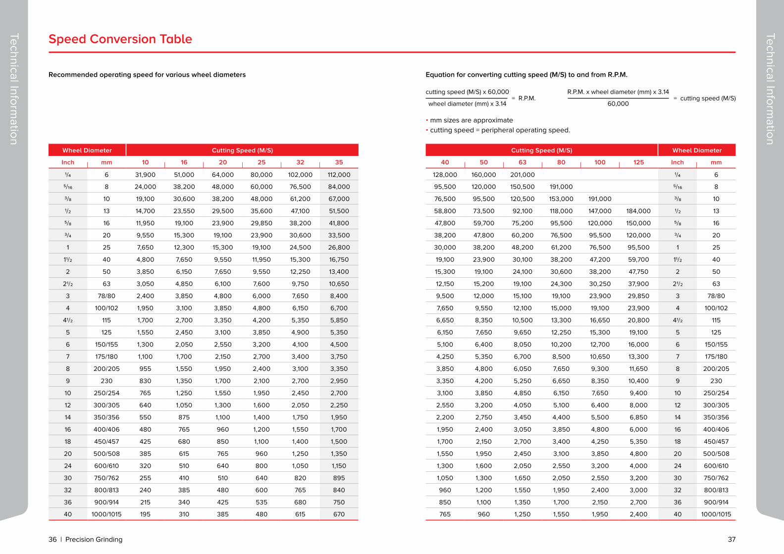
Wheel Diameter Cutting Speed (M/S)
Inch mm 10 16 20 25 32 35
1/4 6 31,900 51,000 64,000 80,000 102,000 112,000
5/16 8 24,000 38,200 48,000 60,000 76,500 84,000
3/8 10 19,100 30,600 38,200 48,000 61,200 67,000
1/2 13 14,700 23,550 29,500 35,600 47,100 51,500
5/8 16 11,950 19,100 23,900 29,850 38,200 41,800
3/4 20 9,550 15,300 19,100 23,900 30,600 33,500
1 25 7,650 12,300 15,300 19,100 24,500 26,800
11/2 40 4,800 7,650 9,550 11,950 15,300 16,750
2 50 3,850 6,150 7,650 9,550 12,250 13,400
21/2 63 3,050 4,850 6,100 7,600 9,750 10,650
3 78/80 2,400 3,850 4,800 6,000 7,650 8,400
4 100/102 1,950 3,100 3,850 4,800 6,150 6,700
41/2 115 1,700 2,700 3,350 4,200 5,350 5,850
5 125 1,550 2,450 3,100 3,850 4,900 5,350
6 150/155 1,300 2,050 2,550 3,200 4,100 4,500
7 175/180 1,100 1,700 2,150 2,700 3,400 3,750
8 200/205 955 1,550 1,950 2,400 3,100 3,350
9 230 830 1,350 1,700 2,100 2,700 2,950
10 250/254 765 1,250 1,550 1,950 2,450 2,700
12 300/305 640 1,050 1,300 1,600 2,050 2,250
14 350/356 550 875 1,100 1,400 1,750 1,950
16 400/406 480 765 960 1,200 1,550 1,700
18 450/457 425 680 850 1,100 1,400 1,500
20 500/508 385 615 765 960 1,250 1,350
24 600/610 320 510 640 800 1,050 1,150
30 750/762 255 410 510 640 820 895
32 800/813 240 385 480 600 765 840
36 900/914 215 340 425 535 680 750
40 1000/1015 195 310 385 480 615 670
Equation for converting cutting speed (M/S) to and from R.P.M.
cutting speed (M/S) x 60,000
wheel diameter (mm) x 3.14= R.P.M.
R.P.M. x wheel diameter (mm) x 3.14
60,000= cutting speed (M/S)
Cutting Speed (M/S) Wheel Diameter
40 50 63 80 100 125 Inch mm
128,000 160,000 201,000 1/4 6
95,500 120,000 150,500 191,000 5/16 8
76,500 95,500 120,500 153,000 191,000 3/8 10
58,800 73,500 92,100 118,000 147,000 184,000 1/2 13
47,800 59,700 75,200 95,500 120,000 150,000 5/8 16
38,200 47,800 60,200 76,500 95,500 120,000 3/4 20
30,000 38,200 48,200 61,200 76,500 95,500 1 25
19,100 23,900 30,100 38,200 47,200 59,700 11/2 40
15,300 19,100 24,100 30,600 38,200 47,750 2 50
12,150 15,200 19,100 24,300 30,250 37,900 21/2 63
9,500 12,000 15,100 19,100 23,900 29,850 3 78/80
7,650 9,550 12,100 15,000 19,100 23,900 4 100/102
6,650 8,350 10,500 13,300 16,650 20,800 41/2 115
6,150 7,650 9,650 12,250 15,300 19,100 5 125
5,100 6,400 8,050 10,200 12,700 16,000 6 150/155
4,250 5,350 6,700 8,500 10,650 13,300 7 175/180
3,850 4,800 6,050 7,650 9,300 11,650 8 200/205
3,350 4,200 5,250 6,650 8,350 10,400 9 230
3,100 3,850 4,850 6,150 7,650 9,400 10 250/254
2,550 3,200 4,050 5,100 6,400 8,000 12 300/305
2,200 2,750 3,450 4,400 5,500 6,850 14 350/356
1,950 2,400 3,050 3,850 4,800 6,000 16 400/406
1,700 2,150 2,700 3,400 4,250 5,350 18 450/457
1,550 1,950 2,450 3,100 3,850 4,800 20 500/508
1,300 1,600 2,050 2,550 3,200 4,000 24 600/610
1,050 1,300 1,650 2,050 2,550 3,200 30 750/762
960 1,200 1,550 1,950 2,400 3,000 32 800/813
850 1,100 1,350 1,700 2,150 2,700 36 900/914
765 960 1,250 1,550 1,950 2,400 40 1000/1015
Speed Conversion Table
Recommended operating speed for various wheel diameters
Technical Information
Technical Information
• mm sizes are approximate • cutting speed = peripheral operating speed.

38 | Precision Grinding 39
Inches mm Inches mm Inches mm Inches mm
1/64 0.397 9/16 14.287 115/16 49.212 6 152.400
1/32 0.794 5/8 15.875 2 50.800 7 177.800
3/64 1.190 11/16 17.462 21/8 53.975 8 203.200
1/16 1.587 3/4 19.050 21/4 57.150 9 228.600
5/64 1.984 13/16 20.637 23/8 60.325 10 254.000
3/32 2.381 7/8 22.225 21/2 63.500 11 279.400
7/64 2.778 15/16 23.812 25/8 66.675 12 304.800
1/8 3.175 1 25.400 23/4 69.850 13 330.200
9/64 3.571 11/16 26.987 27/8 73.025 14 355.600
5/32 3.968 11/8 28.575 3 76.200 15 381.000
3/16 4.762 13/16 30.162 31/8 79.375 16 406.400
7/32 5.556 11/4 31.750 31/4 82.550 17 431.800
1/4 6.350 15/16 33.337 33/8 85.725 18 457.200
9/32 7.144 13/8 34.925 31/2 88.900 19 482.600
5/16 7.937 17/16 36.512 35/8 92.075 20 508.000
11/32 8.731 11/2 38.100 33/4 95.250 21 533.400
3/8 9.525 19/16 39.687 37/8 98.425 22 558.800
13/32 10.319 15/8 41.275 4 101.600 23 584.200
7/16 11.112 111/16 42.862 41/4 107.950 24 609.600
15/32 11.906 13/4 44.450 41/2 114.300 25 635.000
1/2 12.700 113/16 46.037 43/4 120.650 26 660.400
17/32 13.494 17/8 47.625 5 127.000 27 685.800
Mesh Inches Microns Mesh Inches Microns Radius (from - to) Mesh Inches Microns Radius (from - to)
4 .2577 6848 36 .0280 710 180 .0034 86
6 .2117 5630 46 .0200 508 xx - 0.5 220 .0026 66 0.07 - 0.12
8 .1817 4620 54 .0170 430 0.43 - 0.5 240 .00248 63
10 .1366 3460 60 .0160 406 0.4 - 0.5 280 .00175 44
12 .1003 2550 70 .0131 328 320 .00128 32
14 .0830 2100 80 .0105 266 0.25 - 0.5 400 .00090 23
16 .0655 1660 90 .0085 216 500 .00065 16
20 .0528 1340 100 .0068 173 0.2 - 0.25 600 .00033 8
24 .0408 1035 120 .0056 142 0.12 - 0.2 900 .00024 6
30 .0365 930 150 .0048 122 0.1 - 0.15
Grain Size Conversion Table Inch/Millimeter Conversion Table
Technical Information
Technical Information
Product Qty Product Qty
Segments, blocks 50 Wheel diameter 10” - 12” 10
Sticks 100 Wheel diameter 14” - 16” 5
Mounted points 200 Wheel diameter 18”- 48” 2
Wheel diameter less than 3” 100 Non-reinforced cutting discs 200
Wheel diameter 4” - 5” 50 Reinforced cutting discs 500
Wheel diameter 6”, 7”, 8” 40 Wheel thickness up to 5mm, diameter up to 250mm 50
Minimum Quantities for Production of Vitrified Abrasive Products

40 | Precision Grinding
Cutting and Grinding Discs
CGW’s comprehensive line of quality products for cutting and grinding iron, steel, concrete, stainless steel, and aluminium, provide the ideal solution for skilled professionals and amateurs alike.
Our wide range of discs is available in diameters from 100-400 mm (4” to 16”), suitable for all grinders and saws.
Cutting and G
rinding

For more information visit us at:
www.cgwheels.com

U.S.A.
7525 N Oak Park Ave. Niles, IL 60714
Tel. 800-447-4248
Fax. 800-447-3731
www.cgwabrasives.com
Tel. 972 4 6507216
Fax. 972 4 6540899
Worldwide Headquarters:
Kibbutz Sarid 3658900, Israel
www.cgwheels.com