Precautions and safeguards during in-situ · PDF filePrecautions and safeguards during in-situ...
13
1 KNOWLEDGE OF BALANCING AND VIBRATION MEASUREMENT Precautions and safeguards during in-situ balancing Balancing is the process by which the mass distribution of a rotor is checked and, if necessary, adjusted to ensure that the residual unbalance or the vibrations of the journals/bearing supports and/or forces at the bearings are within specified limits. Many rotors are balanced in specially designed balancing facilities prior to installation into their bearings on site. However, if remedial work is carried out locally or a balancing machine is not available, it is becoming increasingly common to balance the rotor in situ. In-situ balancing is the process of balancing a rotor in its own bearings and support structure, rather than in a balancing machine. In-situ balancing shall only be undertaken by a skilled team, including both customer and supplier, who understand the consequences of adding trial and correction masses and have experience of operating the machine. Failure to do this can place the whole machine and staff at risk. While undertaking in-situ balancing, the machine will be operated under special conditions, allowing access to rotating components to add trial and final correction masses. Strict safety procedures shall be in place to ensure that the machine cannot be rotated while personnel have access to the shaft and that no temporary equipment can become entwined when the shaft is rotated. Machines may be quickly run up and run down many times and can have unusual loading conditions during the in-situ balancing exercise, which could be outside the normal operating envelope of a machine. It shall be established that such operations will not be detrimental to the integrity or the life of the whole machine. However, as no general list of machine types can cover all situations, it is necessary to review individually the integrity requirements for each in-situ balance.
-
Upload
nguyenhanh -
Category
Documents
-
view
214 -
download
2
Transcript of Precautions and safeguards during in-situ · PDF filePrecautions and safeguards during in-situ...

1
KNOWLEDGE OF BALANCING AND VIBRATION MEASUREMENT
Precautions and safeguards during in-situ balancing
Balancing is the process by which the mass distribution of a rotor is checked and, if necessary,
adjusted to ensure that the residual unbalance or the vibrations of the journals/bearing supports
and/or forces at the bearings are within specified limits. Many rotors are balanced in specially
designed balancing facilities prior to installation into their bearings on site. However, if remedial
work is carried out locally or a balancing machine is not available, it is becoming increasingly
common to balance the rotor in situ.
In-situ balancing is the process of balancing a rotor in its own bearings and support structure, rather
than in a balancing machine.
In-situ balancing shall only be undertaken by a skilled team, including both customer and supplier,
who understand the consequences of adding trial and correction masses and have experience of
operating the machine. Failure to do this can place the whole machine and staff at risk.
While undertaking in-situ balancing, the machine will be operated under special conditions, allowing
access to rotating components to add trial and final correction masses. Strict safety procedures shall
be in place to ensure that the machine cannot be rotated while personnel have access to the shaft
and that no temporary equipment can become entwined when the shaft is rotated.
Machines may be quickly run up and run down many times and can have unusual loading conditions
during the in-situ balancing exercise, which could be outside the normal operating envelope of a
machine. It shall be established that such operations will not be detrimental to the integrity or the
life of the whole machine.
However, as no general list of machine types can cover all situations, it is necessary to review
individually the integrity requirements for each in-situ balance.

2
Turbines (Steam and gas turbines)
Before a turbine shaft is stopped to add correction masses or establish phase signal references, it
shall be confirmed that the correct procedures are undertaken to prevent bending of the shaft. This
normally involves barring for a period of time to reduce the shaft temperature.
The rotor life can be related to the number of machine starts and this need to be taken into account
in relation to the starts required for the in-situ balancing runs.
Electric motors
Some electric motors have restrictions on the number of starts per hour and this shall not be
exceeded.
Electric motors can run from zero to full speed with no intermediate control. Trial masses shall be of a
size that will not cause damage to the machine, even if placed in the wrong position.
Pumps
Some pumps need to be full of fluid for their safe operation and in-situ balancing runs will not
generally be an exception.
Large fans
During the in-situ balancing runs, the flow induced by the fan shall be correctly accommodated. For
example, dampers may need to be shut and this might place the fan under stall conditions.
The fans might be delivering hot or hazardous fluids and personnel shall not be allowed to enter the
fan to add correction masses until conditions are safe.
Electrical generators
The considerations related to the turbines apply also to the generators.
It shall be established that the seal oil system will provide adequate lubrication of the gland seals
when the generator is running in air.
For easy access to the internal in-situ balancing planes, it may be necessary to dismantle some of the
internal baffling of the cooling circuit.
The effect on generator cooling and cleanness shall be taken into account when making such
modifications.

3
When trial and correction masses are added, it shall be confirmed that they are securely attached
and their mountings are capable of carrying the required loads. The correction masses shall not
interfere with normal operation, such as coming into contact with stationary components due to
shaft expansion. The correction masses should be fitted in accordance with the manufacturers’
instructions, if available.
Correction masses are often attached with bolts or by welding. It shall be ensured that the bolt holes
or the welding process do not compromise the integrity of the rotor component to which the
correction masses are attached, or the function of the component, such as cooling. Furthermore,
correction masses shall be compatible with their operating environment, such as heat and chemical
atmosphere.
Where possible, the total mass of the correction masses on each plane shall be minimized by
consolidating those added from previous balancing exercises. However, correction masses that have
been added for specific reasons (such as to balance the individual disc or counteract for blade root
eccentricity errors) should not be changed.
Conclusion
As no general list of safety precautions can cover all machinery and all situations, it is necessary to
review individually the safety requirements for each in-situ balance.
Bibliography
ISO 20806 - 2004, Mechanical vibration — Criteria and safeguards for the in-situ balancing of medium
and large rotors
ISO 1940-1 – 2003, Mechanical vibration — Balance quality requirements for rotors in a constant
(rigid) state — Part 1: Specification and verification of balance tolerances
ISO 1925:2001, Mechanical vibration — Balancing — Vocabulary
ISO 2041, Vibration and shock — Vocabulary

4
Consideration regarding field balancing
Introduction
Balancing is the process by which the mass distribution of a rotor is checked and, if necessary,
adjusted to ensure that the residual unbalance or the vibrations of the journals/bearing supports
and/or forces at the bearings are within specified limits. Many rotors are balanced in specially
designed balancing facilities prior to installation into their bearings on site. However, if remedial
work is carried out locally or a balancing machine is not available, it is becoming increasingly
common to balance the rotor in situ.
Field or In-situ balancing is the process of balancing a rotor in its own bearings and support structure,
rather than in a balancing machine.
Unlike balancing in a specially designed balancing machine, in-situ balancing has the advantage that
the rotor is installed in its working environment. Therefore there is no compromise with regard to
the dynamic properties of its bearings and support structure, nor from the influence of other
elements in the complete rotor train.
However, it has the large disadvantage of restricted access and the need to operate the whole
machine. Restricted access can limit the planes at which correction masses can be added, and using
the whole machine has commercial penalties of both downtime and running costs. Where gross
unbalance exists, it may not be possible to balance a rotor in situ due to limited access to balance
planes and the size of correction masses available.
This paper present some common sense consideration when balancing rotors installed in their own
bearings on site. It addresses the conditions under which it is appropriate to undertake in-situ
balancing.
It does not provide guidance on the methods used to calculate the correction masses from measured
vibration data.

5
General consideration
For in-situ balancing, correction masses are added to the rotor at a limited number of conveniently
engineered and accessible locations along the rotor. By doing this the magnitude of shaft and/or
pedestal vibrations and/or unbalance is reduced to within acceptable values, so that the machine can
operate safely throughout its whole operating envelope.
In certain cases, machines that are very sensitive to unbalance may not be successfully balanced over
the complete operating envelope. This usually occurs when a machine is operating at a speed close
to a lightly damped system mode (see ISO 10814), and has load-dependent unbalance.
Most sites have instrumentation with limited data-processing capabilities, when compared to a
balancing facility, and additional measurements will be required to undertake in-situ balancing in
these situations. In addition, the potential safety implications of running a rotor with correction
masses shall be taken into account.
Why balance in-situ?
Although individual rotors may be correctly balanced, as appropriate, in a high- or low-speed
balancing machine, in-situ balancing might be required when the rotors are coupled into the
complete rotor train. This could be due to a range of differences between the real machine and the
isolated environment in the balancing machine, including a difference in dynamic characteristics of
the rotor supports between the balancing facility and the installed machine, assembly errors that
occur during the installation of the machine in situ, rotor systems that cannot be balanced prior to
assembly, and a changing unbalance state of the rotor under full functional operating conditions.
Balancing might also be required to compensate for in-service changes to the rotor, including wear,
loss of components, such as rotor blade erosion shields, repair work, where components could be
changed or replaced, and movement of components on the rotor train causing unbalance, such as
couplings, gas turbine discs and generator end rings.
Additionally in-situ balancing might be necessary due to a range of economic and technical reasons,
including when the investment in a balancing machine cannot be justified, when a suitable balancing
machine is not available in the correct location or at the required time, and when it is not economic
to dismantle the machine and transport the rotor(s) to a suitable balancing facility.
The reason for balancing is to reduce the vibration magnitude(s) to acceptable values for long-term
operation.

6
For most machines, the overall vibration magnitude(s) limits shall either be based on normal practice
or the appropriate part of ISO 10816 and ISO 7919 for pedestals and shafts, respectively.
Where the magnitude of unbalance is important, it is necessary to reduce the magnitude of
unbalance to within permissible limits (see ISO 1940-1).
Action before balancing
Prior to in-situ balancing, a feasibility study shall be carried out to assess if the available correction
planes are suitable to influence the vibration behaviour being observed, since limited access to
correction planes and measurement points on the fully built-up machine can make in-situ balancing
impractical. Where possible, experience from previous in-situ balancing should be used. Sometimes
modal analysis may be required.
In-situ balancing shall only be attempted in the following circumstances:
The reasons for the high vibrations are understood and cannot be corrected at source;
After analysis of the vibration behaviour, it is judged that balancing is a safe and practical approach;
Under the required normal operating conditions, the vibration vector is steady and repeatable prior to in-situ balancing; the addition of corrections masses only affects the once-per-revolution component of vibration and, therefore, in-situ balancing shall only be carried out if this is a significant component of the overall vibration magnitude.
In special circumstances, where the once-per-revolution vibration component changes during normal
operation of the machine (such as thermally induced bends in generator rotors), it is possible to
optimize the vibration magnitude across the operating envelope by adding correction masses. Here,
the vibration magnitude at full speed no load might be compromised to obtain an acceptable
vibration magnitude at full load.
Again, this shall only be attempted if the reasons for the unbalance are understood.
When systems are operating in a non-linear mode, correction masses can affect other vibration
components, including both sub and high shaft speed harmonics.
The once-per-revolution component of vibration might not originate from unbalance but be
generated from system forces such as those seen in hydraulic pumps and electric motors. Many
defects, such as shaft alignment errors and tilting bearings, can also contribute to the once-per-
revolution component of vibration.
Such effects should not normally be corrected by balancing, since balancing will be effective at only a
single speed and could mask a real system fault.
The variation of the vibration vectors should be sufficiently steady such that the amplitude of the
variation is not significant relative to the amplitude of the mean vibration vector.

7
Conclusion
Machines under normal operation and/or during speed variations (following remedial work, or after
commissioning) might have unacceptable magnitudes of vibration when compared with normal
practice, contractual requirements, or International Standards such as the ISO 10816 and ISO 7919
series. In many cases, it may be possible to bring the machine to within acceptable vibration
magnitude by in-situ balancing.
Using Analysis menu of the CXBalancer instrument is possible to do the following tests prior to
perform the in-situ balancing:
- If the overall vibration exceeds the Overall Amplitude Acceptance Limit (based on normal practice or the appropriate part of ISO 10816) or is no need to do any correction action
- If the once-per-revolution component of vibration originate from unbalance or from another fault (such as shaft alignment errors, tilting bearings, etc)
- If under the required normal operating conditions, the vibration vector (X1 RPM) is steady and repeatable
Bibliography
ISO 20806 - 2004, Mechanical vibration — Criteria and safeguards for the in-situ balancing of medium
and large rotors
ISO 1940-1 – 2003, Mechanical vibration — Balance quality requirements for rotors in a constant
(rigid) state — Part 1: Specification and verification of balance tolerances
ISO 1925:2001, Mechanical vibration — Balancing — Vocabulary
ISO 2041, Vibration and shock — Vocabulary
ISO 7919 (all parts), Mechanical vibration — Evaluation of machine vibration by measurements on
rotating shafts
ISO 10816 (all parts), Mechanical vibration — Evaluation of machine vibration by measurements on
non-rotating parts
IS0 10817-1, Rotating shaft vibration measuring systems — Part 1: Relative and absolute sensing of
radial vibration

8
Evaluate Balancing Quality Limits
Is a vibration reading of 5 mm/sec a proper limit for accepting balancing quality of a new forced draft
fan? Is this limit also applicable on a new cooling water pump? How to find an acceptance limit for
variable speed machines? The proper limit is dependent on many factors including rotor mass, speed
and the application in which the machine is used. In fact, the standard limit of balancing quality
acceptance is different from the limits given for accepting vibration levels due to unbalance!
Understanding balancing limits should enable the manufacturer, vendor, owner and service shop to
come up with a doable agreement on target balancing specifications- it is helpful for contractual and
technical purposes.
This simplified article will answer prime questions about balancing quality faced in the process of
accepting balancing quality of newly purchased or serviced machines.
It is based on an interpretative reading of ISO 1940/1. Illustrative figures are given to emphasize the
major concepts of that standard.
Unbalance occurs in a rotating machine when the mass centreline and the geometric centre do not
coincide on each other. Unbalanced rotors generate vibration which may damage their components.
In order to extend the life of the machine, vibration due to unbalance must be reduced to acceptable
level. Despite the ability to reduce unbalance to low levels, these levels or limits must be defined.
It would be uneconomical to exaggerate balancing quality requirements. However, if the balancing
quality is underestimated, it would reduce machine reliability and availability. Moreover, sometimes
demanding overqualified balancing reduces machine availability by consuming necessary time in
unnecessary balancing.
Unbalance and Vibration
Unbalance amount is expressed as:
U = m X r where
m = unbalance mass (in kg)
r = distance from unbalance mass to shaft/rotor centreline (in m)
9
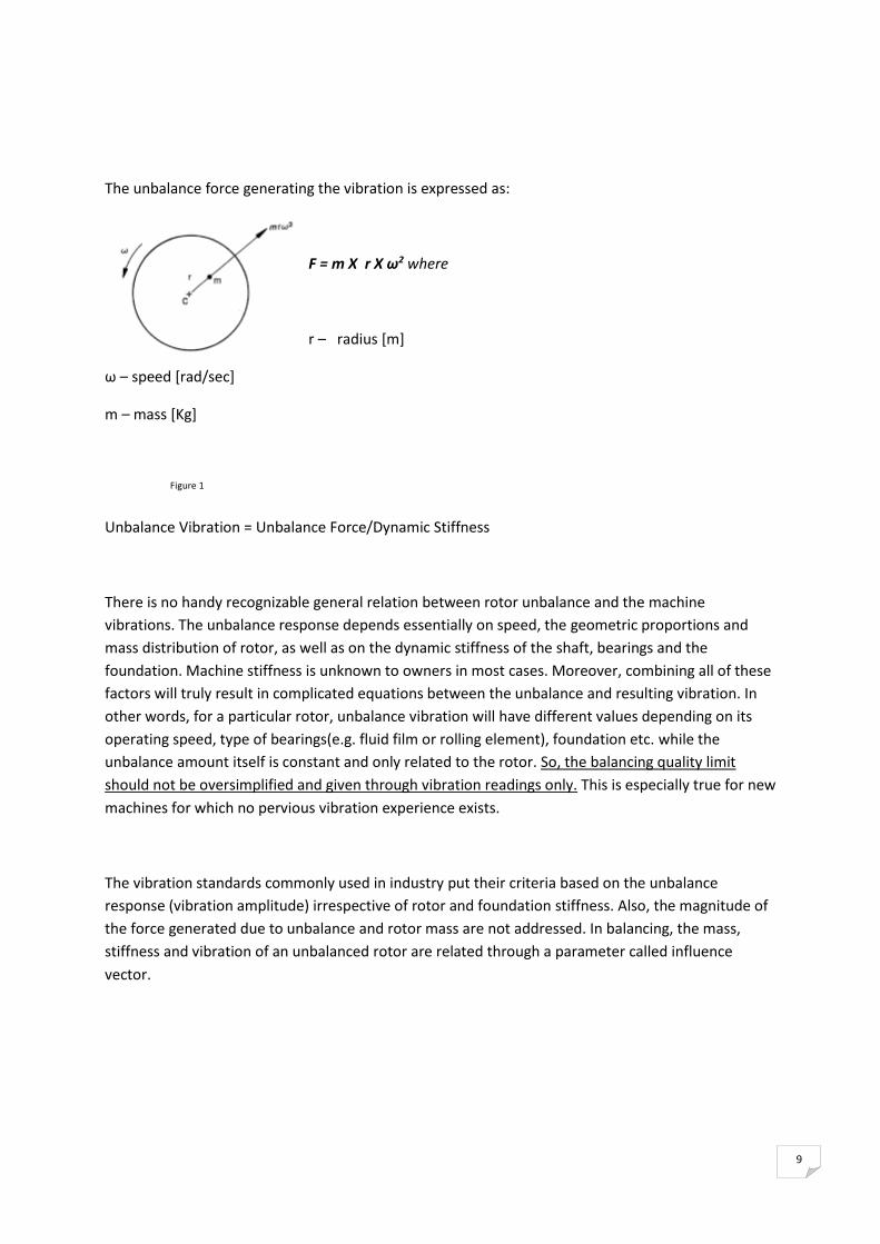
The unbalance force generating the vibration is expressed as:
F = m X r X ω2 where
r – radius [m]
ω – speed [rad/sec]
m – mass [Kg]
Figure 1
Unbalance Vibration = Unbalance Force/Dynamic Stiffness
There is no handy recognizable general relation between rotor unbalance and the machine
vibrations. The unbalance response depends essentially on speed, the geometric proportions and
mass distribution of rotor, as well as on the dynamic stiffness of the shaft, bearings and the
foundation. Machine stiffness is unknown to owners in most cases. Moreover, combining all of these
factors will truly result in complicated equations between the unbalance and resulting vibration. In
other words, for a particular rotor, unbalance vibration will have different values depending on its
operating speed, type of bearings(e.g. fluid film or rolling element), foundation etc. while the
unbalance amount itself is constant and only related to the rotor. So, the balancing quality limit
should not be oversimplified and given through vibration readings only. This is especially true for new
machines for which no pervious vibration experience exists.
The vibration standards commonly used in industry put their criteria based on the unbalance
response (vibration amplitude) irrespective of rotor and foundation stiffness. Also, the magnitude of
the force generated due to unbalance and rotor mass are not addressed. In balancing, the mass,
stiffness and vibration of an unbalanced rotor are related through a parameter called influence
vector.

10
Unbalance: Existing and Limits
The term "unbalance" is referred to two quantities. First is the balancing acceptance limit of a rotor
and is usually called permissible or allowable unbalance. Second is the existing or residual unbalance
in a rotor. In acceptance tests, the following logic is implicitly applied:
ULimit > UExisting Balancing Quality within Tolerance (Accepted)
ULimit < UExisting Balancing Quality out of Tolerance (Rejected)
This paper is dedicated to highlight the determination of permissible unbalance.
Determination of residual unbalance is left for another article.
Balance Quality Determination Methods
The permissible unbalance can be determined based on:
1. History and/or experiments done on several similar machines (vibration limits can be extracted
from the history)
2. Pre-specified permissible bearing forces in the stage of bearing selection
3. Standards like 1940/1 (typically followed in industry)
Balance Quality Based on Standardized Grades
The standard is valid only for rigid rotors and does not define permissible residual unbalances for
flexible rotors. A rotor is considered rigid if it does not run above its first critical speed through its
operation up to its maximum service speed.
This standard does not cover neither the sources of errors involved in balancing nor the balancing
procedure. (This information is available in other standards.) . Balancing standard provides
generalized grades for which rotor application, mass, and speed can tailored for specific cases.

11
In general, the larger the rotor mass, the greater the permissible residual unbalance.
To relate the value of the total permissible unbalance, U, to the rotor mass, M, the term specific
permissible unbalance value, u, is defined. It is the maximum limit of unbalance amount per unit
mass of the rotor. It is analogous to the specific enthalpy or specific entropy used in
thermodynamics.
Mathematically, u = eper = U/M [um X g/kg], where u = permissible specific unbalance (sometimes
referred to as mass eccentricity), U = rotor total permissible unbalance [um X g], M = rotor mass [kg].
Quality grade (the lines in the figure) relates max service speed2 to the permissible specific
unbalance. For a specific grade, as the speed of the rotor increases (rightwards in the figure), u gets
tighter (downwards). This means that the unbalance amount allowed deceases as machine speed
increases.
Figure 2

12
Table 1
Quantity Symbol Units
Balance Grade Code G mm/sec
Rotor Mass M Kg
Unbalance Mass m gram
Total Permissible Unbalance U gr X mm
Specific Permissible Unbalance u, eper gr X mm/Kg
Total Residual Unbalance Ures gr X mm
Specific Residual Unbalance ures gr X mm/Kg
Instead of using the graph to look up the specific unbalance value for a given G number and service
RPM and then multiplying by rotor weight (taking care to use proper units), u and U can be calculated
by using the following formulas:
u = eper = 9549 x G/S[Kg] in [gr x mm/Kg]
U = u x M [Kg] in [gr X mm]
U = 9549 x G x M [kg] /S[RPM] in [gr X mm] , where S is the maximum service speed (in RPM).
Table 2 – Balance Grade
Application Grade
Drive shafts (propeller shafts) with special requirements. Parts of crushing machinery. Parts of agricultural machinery. Pump impeller. Individual components of engines (gas or diesel) for cars, trucks and locomotives. Crankshaft drives of engines with six or more cylinders under special requirements.
G 16
Parts or process plant machines. Fans. Fly wheels. Pump impellers. Machine tool and general machinery parts. Normal electrical armatures. Individual components of engines under special requirements Marine main turbine gears (merchant service).
G 6.3
Gas & steam turbines, including marine main turbines. Rigid turbo-generator rotors. Turbo-compressors. Machine tool drives. Medium and large electrical armatures with special requirements. Small electrical armatures. Turbine driven pumps.
G 2.5
Grinding machine drives. Small electrical armatures with special requirements. G 1

13
General Procedure of Finding U
The steps described below may be applied to all rotors regardless of their mass distribution and the
position of the correction planes.
1. Gather machine's design and operation information (minimum: speed, mass and criticality).
2. Using Table 2, compare this information and decide the proper balance grade.
3. Specify the Grade line and the max service speed in Figure 2.
4. Impose the max service speed of the rotor and then determine the corresponding permissible
specific unbalance value, u.
5. Multiply u by rotor mass to obtain the total permissible unbalance, U.
6. Allocate U to the balancing correction planes based on rotor configuration.
Notes on Step 6: This step involves a series of calculation based on the mass distribution of the rotor
and the location of the correction plane. Usually, these calculations can be reduced to get an
approximate result. The Total Permissible Unbalance per plane would be approximated by ½ U in
case two correction planes would be used.
Example:
Find the allocated permissible unbalance of a critical induction motor rotor of the following
information:
Operation speed: 1500 rpm, Mass =150 kg, running under sever conditions, two balancing planes
close to the bearings and measurement planes are available.
Using the table, G2.5 is selected. Compensating sever load conditions for this motor, max service
speed is increased to 2000 rpm. Using the formula: U= 9549 X 2.5
X150/2000 result a total permissible unbalance of 1790 g X mm.
Allocating U to the two plane with the approximate method, U1=U2= U/2= 895 g X mm.
Caution: This article does not replace the original standard by any means.
For more details, the complete title of the Standard is:
ISO 1940-1: Mechanical Vibration - Balance Quality Requirements of Rigid Rotors - Determination of
Permissible Residual Unbalance.