PRECAST BULB-T SECTIONS: CONCRETE: … precast concrete Bulb-T’s sections (PCBT-series) adopted by...
12
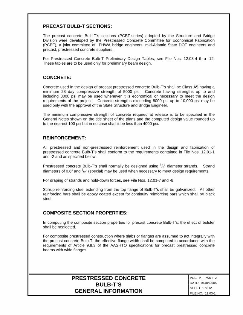
VOL. V - PART 2 DATE: 01Jun2005 SHEET 1 of 12 PRESTRESSED CONCRETE BULB-T’S GENERAL INFORMATION FILE NO. 12.03-1 PRECAST BULB-T SECTIONS: The precast concrete Bulb-T’s sections (PCBT-series) adopted by the Structure and Bridge Division were developed by the Prestressed Concrete Committee for Economical Fabrication (PCEF), a joint committee of FHWA bridge engineers, mid-Atlantic State DOT engineers and precast, prestressed concrete suppliers. For Prestressed Concrete Bulb-T Preliminary Design Tables, see File Nos. 12.03-4 thru -12. These tables are to be used only for preliminary beam design. CONCRETE: Concrete used in the design of precast prestressed concrete Bulb-T’s shall be Class A5 having a minimum 28 day compressive strength of 5000 psi. Concrete having strengths up to and including 8000 psi may be used whenever it is economical or necessary to meet the design requirements of the project. Concrete strengths exceeding 8000 psi up to 10,000 psi may be used only with the approval of the State Structure and Bridge Engineer. The minimum compressive strength of concrete required at release is to be specified in the General Notes shown on the title sheet of the plans and the computed design value rounded up to the nearest 100 psi but in no case shall it be less than 4000 psi. REINFORCEMENT: All prestressed and non-prestressed reinforcement used in the design and fabrication of prestressed concrete Bulb-T’s shall conform to the requirements contained in File Nos. 12.01-1 and -2 and as specified below. Prestressed concrete Bulb-T’s shall normally be designed using 1 / 2 ” diameter strands. Strand diameters of 0.6” and 1 / 2 ” (special) may be used when necessary to meet design requirements. For draping of strands and hold-down forces, see File Nos. 12.01-7 and -8. Stirrup reinforcing steel extending from the top flange of Bulb-T’s shall be galvanized. All other reinforcing bars shall be epoxy coated except for continuity reinforcing bars which shall be black steel. COMPOSITE SECTION PROPERTIES: In computing the composite section properties for precast concrete Bulb-T’s, the effect of bolster shall be neglected. For composite prestressed construction where slabs or flanges are assumed to act integrally with the precast concrete Bulb-T, the effective flange width shall be computed in accordance with the requirements of Article 9.8.3 of the AASHTO specifications for precast prestressed concrete beams with wide flanges.
Transcript of PRECAST BULB-T SECTIONS: CONCRETE: … precast concrete Bulb-T’s sections (PCBT-series) adopted by...
VOL. V - PART 2 DATE: 01Jun2005 SHEET 1 of 12
PRESTRESSED CONCRETE BULB-T’S
GENERAL INFORMATION FILE NO. 12.03-1
PRECAST BULB-T SECTIONS: The precast concrete Bulb-T’s sections (PCBT-series) adopted by the Structure and Bridge Division were developed by the Prestressed Concrete Committee for Economical Fabrication (PCEF), a joint committee of FHWA bridge engineers, mid-Atlantic State DOT engineers and precast, prestressed concrete suppliers. For Prestressed Concrete Bulb-T Preliminary Design Tables, see File Nos. 12.03-4 thru -12. These tables are to be used only for preliminary beam design. CONCRETE: Concrete used in the design of precast prestressed concrete Bulb-T’s shall be Class A5 having a minimum 28 day compressive strength of 5000 psi. Concrete having strengths up to and including 8000 psi may be used whenever it is economical or necessary to meet the design requirements of the project. Concrete strengths exceeding 8000 psi up to 10,000 psi may be used only with the approval of the State Structure and Bridge Engineer. The minimum compressive strength of concrete required at release is to be specified in the General Notes shown on the title sheet of the plans and the computed design value rounded up to the nearest 100 psi but in no case shall it be less than 4000 psi. REINFORCEMENT: All prestressed and non-prestressed reinforcement used in the design and fabrication of prestressed concrete Bulb-T’s shall conform to the requirements contained in File Nos. 12.01-1 and -2 and as specified below. Prestressed concrete Bulb-T’s shall normally be designed using 1/2” diameter strands. Strand diameters of 0.6” and 1/2” (special) may be used when necessary to meet design requirements. For draping of strands and hold-down forces, see File Nos. 12.01-7 and -8. Stirrup reinforcing steel extending from the top flange of Bulb-T’s shall be galvanized. All other reinforcing bars shall be epoxy coated except for continuity reinforcing bars which shall be black steel. COMPOSITE SECTION PROPERTIES: In computing the composite section properties for precast concrete Bulb-T’s, the effect of bolster shall be neglected. For composite prestressed construction where slabs or flanges are assumed to act integrally with the precast concrete Bulb-T, the effective flange width shall be computed in accordance with the requirements of Article 9.8.3 of the AASHTO specifications for precast prestressed concrete beams with wide flanges.
VOL. V - PART 2 DATE: 31Mar2006 SHEET 2 of 12
PRESTRESSED CONCRETE BULB-T’S
GENERAL INFORMATION FILE NO. 12.03-2
MEMBER WEIGHT AND LENGTH LIMITATIONS: The weight of any precast prestressed concrete Bulb-T shall be limited to 72,000 lbs. and the length limited to 75 feet in order to allow hauling by truck. When investigating the possibilities of greater lengths or heavier sections, the designer should consult with the Materials Division, District Structure and Bridge Engineer or fabricator to verify that the member can be hauled to the site. BEAM END DETAILS FOR INTEGRAL ABUTMENTS: For beam end details for integral abutments, see File Nos. 20.05-5 thru -8. The designer shall locate 11/2” diameter open holes to insure there are no conflicts with prestressing strands. In the event this is not possible, the designer may consider the option of relocating the draped strands providing the beam stresses do not exceed the allowable. When relocating draped strands, the designer may increase the vertical spacing of strands but shall maintain 2” increments between rows of draped strands. Modify the end of the beam shown in the Part Plan and Part Elevation shown on the prestressed concrete beam standard sheet to show the location of the 11/2” diameter open holes in the beam web. For semi-integral abutments for bridges on skews, modify the Part Plan to show the top flange clip or beam end bevel. BEAM DIAPHRAGM DETAILS: For beam diaphragm details, see File Nos. 12.10-1 thru -10. For beam continuity diaphragm details, see File Nos. 12.11-1 thru -13. MISCELLANEOUS BEAM DETAILS: For camber and bolster computations, see File Nos. 12.02-1 and -2. For dead load deflection diagrams, see File No. 12.02-3. For top of slab elevations, see File No. 12.02-4. S&B STANDARD DETAIL SHEETS AND CELL LIBRARIES: See Introduction File No. 12.00-1.

VOL. V - PART 2
Maximum number of strands in row number 1: 14 2: 14 3: 12 4: 6 5 and higher: 2
Section Modulus Depth Area
Centroid to
Bottom
Moment of
Inertia
D A yb I Stop Sbott
Weight @
150 pcf Beam
Designation
(in) (in2) (in) (x 103 in4) (in3) (in3) (lbs/lin. ft.)
PCBT-29 29 643.7 14.66 66.8 4658 4557 661 PCBT-37 37 690.7 18.43 126.0 6785 6837 720 PCBT-45 45 746.7 22.23 207.3 9104 9325 778 PCBT-53 53 802.7 26.06 312.4 11596 11988 836 PCBT-61 61 858.7 29.92 443.1 14257 14810 899 PCBT-69 69 914.7 33.79 601.3 17078 17795 953 PCBT-77 77 970.7 37.67 788.7 20053 20937 1011 PCBT-85 85 1026.7 41.57 1007.2 23191 24229 1070 PCBT-93 93 1082.7 45.48 1258.5 26484 27672 1128
DATE: 01Jun2005 SHEET 3 of 12
PRESTRESSED CONCRETE BULB-T’S
SECTION PROPERTIES FILE NO. 12.03-3

VOL. V - PART 2
BEAM SPACING = 6’ – 0” Number of 1/2” diameter strands
PCBT-29 PCBT-37 PCBT-45 PCBT-53 PCBT-61 PCBT-69 PCBT-77 PCBT-85 PCBT-93Span Length
L
(ft.) f ’c =
500
0 ps
i 60
00 p
si
7000
psi
80
00 p
si
f ’c =
500
0 ps
i 60
00 p
si
7000
psi
80
00 p
si
f ‘c =
500
0 ps
i 60
00 p
si
7000
psi
80
00 p
si
f ’c =
500
0 ps
i 60
00 p
si
7000
psi
80
00 p
si
f ’c =
500
0 ps
i 60
00 p
si
7000
psi
80
00 p
si
f ’c =
500
0 ps
i 60
00 p
si
7000
psi
80
00 p
si
f ’c =
500
0 ps
i 60
00 p
si
7000
psi
80
00 p
si
f ’c =
500
0 ps
i 60
00 p
si
7000
psi
80
00 p
si
f ’c =
500
0 ps
i 60
00 p
si
7000
psi
80
00 p
si
40 12 12 12 12 12 14 14 14 14 16 16 16 16 18 18 18 18 20 20 18 20 20 22 20 20 22 22 20 22 22 24 22 22 24 26
45 14 14 14 12 12 12 14 14 14 16 16 16 16 18 18 16 18 18 20 18 18 20 22 20 20 22 22 20 22 22 24 22 22 24 24
50 16 16 14 14 14 14 12 14 14 16 14 16 16 18 16 18 18 20 18 18 20 20 18 20 20 22 20 20 22 24 20 22 24 24
55 20 20 16 16 16 14 14 14 14 14 16 16 18 16 16 18 18 18 18 20 20 18 20 20 22 20 20 22 22 20 22 22 24
60 24 18 18 18 16 16 16 16 14 14 16 16 16 16 18 18 16 18 18 20 18 20 20 22 18 20 22 22 20 22 22 24
65 20 20 18 18 18 18 16 16 16 16 14 16 16 18 16 18 18 20 18 18 20 20 18 20 20 22 20 20 22 22
70 24 24 20 20 20 20 18 18 18 18 16 16 16 18 16 16 18 20 18 18 20 20 18 20 20 22 20 20 22 22
75 28 28 22 22 22 20 20 20 20 18 18 18 18 16 16 18 18 16 18 20 20 18 20 20 22 18 20 22 22
80 34 24 24 24 22 22 22 22 18 18 18 18 18 18 18 18 16 16 18 20 16 18 20 22 18 20 22 22
85 28 28 28 24 24 24 24 20 20 20 20 18 18 18 18 18 18 18 20 16 18 20 20 18 20 20 22
90 34 32 26 26 26 26 22 22 22 22 20 20 20 20 18 18 18 18 18 18 18 20 16 18 20 22
95 38 38 30 30 28 26 26 26 26 22 22 22 22 20 20 20 20 20 20 20 20 18 18 20 22
100 44 34 34 34 28 28 28 28 24 24 24 24 22 22 22 22 20 20 20 20 20 20 20 20
105 38 38 38 32 32 32 30 28 26 26 26 24 24 24 24 22 22 22 22 22 22 22 22
110 44 44 36 36 34 34 30 30 30 30 26 26 26 26 24 24 24 24 22 22 22 22
115 50 50 40 40 38 34 34 32 32 30 28 28 28 26 26 26 26 24 24 24 24
120 44 44 44 40 38 36 36 32 32 32 32 28 28 28 28 26 26 26 26
125 50 48 42 40 40 36 36 36 34 32 32 30 30 28 28 28 28
130 48 46 44 50 40 38 38 36 34 34 34 32 30 30 30
135 50 50 44 42 42 38 38 38 36 34 34 34 32
140 48 46 42 42 40 38 38 36 36
145 46 46 44 46 40 40 40
150 50 50 44 44 44
155 50 48 48
160
Strands: Seven-wire, Grade 270 low-relaxation strands, 2” grid (spacing), drape points at 0.4L
and 0.6L. Slab thickness: 71/2” (including 1/2” w.s.). Dead loads: Non-composite = 0.20 kips/ft. (excluding weight of beam and slab)
Composite = 0.27 kips/ft. Live load: HS20-44. Allowable tension = '
cf6 Strand designs shown in shaded bold type exceed maximum number of draped strands (14) or maximum total uplift force (48 kips) for strand restraining devices. Additional investigation by designer is required.
DATE: 01Jun2005 SHEET 4 of 12
PRESTRESSED CONCRETE BULB-T’S
PRELIMINARY DESIGN TABLES FILE NO. 12.03-4

VOL. V - PART 2
BEAM SPACING = 6’ – 6” Number of 1/2” diameter strands
PCBT-29 PCBT-37 PCBT-45 PCBT-53 PCBT-61 PCBT-69 PCBT-77 PCBT-85 PCBT-93Span Length
L
(ft.) f ’c =
500
0 ps
i 60
00 p
si
7000
psi
80
00 p
si
f ’c =
500
0 ps
i 60
00 p
si
7000
psi
80
00 p
si
f ’c =
500
0 ps
i 60
00 p
si
7000
psi
80
00 p
si
f ’c =
500
0 ps
i 60
00 p
si
7000
psi
80
00 p
si
f ’c =
500
0 ps
i 60
00 p
si
7000
psi
80
00 p
si
f ’c =
500
0 ps
i 60
00 p
si
7000
psi
80
00 p
si
f ’c =
500
0 ps
i 60
00 p
si
7000
psi
80
00 p
si
f ’c =
500
0 ps
i 60
00 p
si
7000
psi
80
00 p
si
f ’c =
500
0 ps
i 60
00 p
si
7000
psi
80
00 p
si
40 12 12 12 12 12 14 14 14 16 16 16 16 16 18 18 18 18 20 20 18 20 20 22 20 22 22 24 20 22 24 24 22 24 24 26
45 14 14 12 12 12 14 14 14 16 16 16 16 18 18 16 18 18 20 18 20 20 22 20 20 22 22 20 22 22 24 22 22 24 26
50 18 14 14 14 14 12 14 14 16 14 16 16 18 16 18 18 20 18 18 20 20 18 20 22 22 20 22 22 24 22 22 24 24
55 16 16 16 14 14 14 14 14 16 16 18 16 16 18 18 18 18 20 20 18 20 20 22 20 20 22 22 20 22 24 24
60 18 18 16 16 16 16 14 14 16 16 16 16 18 18 16 18 18 20 18 20 20 22 20 20 22 22 20 22 22 24
65 22 22 18 18 18 16 16 16 16 14 16 16 18 16 18 18 20 18 18 20 20 18 20 22 22 20 20 22 24
70 26 24 20 20 20 18 18 18 18 16 16 16 18 16 16 18 20 18 18 20 20 18 20 20 22 20 20 22 22
75 24 24 24 20 20 20 20 18 18 18 18 16 16 18 18 16 18 20 20 18 20 20 22 18 20 22 22
80 26 26 26 22 22 22 22 20 20 20 20 18 18 18 18 16 16 18 20 16 18 20 22 18 20 22 22
85 30 30 24 24 24 24 22 22 22 22 20 20 20 20 18 18 18 20 16 18 20 20 18 20 20 22
90 36 34 28 28 28 24 24 24 24 22 22 22 22 20 20 20 20 18 18 18 20 18 18 20 22
95 40 32 32 30 26 26 26 26 24 24 24 24 22 22 22 22 20 20 20 20 18 18 20 22
100 36 36 30 30 28 26 26 26 26 24 24 24 24 22 22 22 22 20 20 20 20
105 40 40 34 32 32 28 28 28 28 26 26 26 26 24 24 24 24 22 22 22 22
110 46 46 38 38 36 32 32 32 30 28 28 28 28 26 26 26 26 24 24 24 24
115 52 42 42 42 36 36 34 34 32 30 30 30 28 28 28 28 26 26 26 26
120 48 46 40 38 38 34 34 34 32 30 30 30 30 28 28 28 28
125 54 52 44 44 42 38 38 38 36 34 34 32 32 30 30 30 30
130 48 48 42 42 40 38 36 36 36 34 32 32 32
135 54 54 46 46 44 44 40 40 38 36 36 36 34
140 50 50 44 44 42 40 40 38 38
145 54 48 48 48 42 42 42
150 52 52 48 46 46
155 54 52 50
160
Strands: Seven-wire, Grade 270 low-relaxation strands, 2” grid (spacing), drape points at 0.4L
and 0.6L. Slab thickness: 71/2” (including 1/2” w.s.). Dead loads: Non-composite = 0.21 kips/ft. (excluding weight of beam and slab).
Composite = 0.27 kips/ft. Live load: HS20-44. Allowable tension = '
cf6 Strand designs shown in shaded bold type exceed maximum number of draped strands (14) or maximum total uplift force (48 kips) for strand restraining devices. Additional investigation by designer is required.
DATE: 01Jun2005 SHEET 5 of 12
PRESTRESSED CONCRETE BULB-T’S
PRELIMINARY DESIGN TABLES FILE NO. 12.03-5

VOL. V - PART 2
BEAM SPACING = 7’ – 0” Number of 1/2” diameter strands
PCBT-29 PCBT-37 PCBT-45 PCBT-53 PCBT-61 PCBT-69 PCBT-77 PCBT-85 PCBT-93Span Length
L
(ft.) f ’c =
500
0 ps
i 60
00 p
si
7000
psi
80
00 p
si
f ’c =
500
0 ps
i 60
00 p
si
7000
psi
80
00 p
si
f ’c =
500
0 ps
i 60
00 p
si
7000
psi
80
00 p
si
f ’c =
500
0 ps
i 60
00 p
si
7000
psi
80
00 p
si
f ’c =
500
0 ps
i 60
00 p
si
7000
psi
80
00 p
si
f ’c =
500
0 ps
i 60
00 p
si
7000
psi
80
00 p
si
f ’c =
500
0 ps
i 60
00 p
si
7000
psi
80
00 p
si
f ’c =
500
0 ps
i 60
00 p
si
7000
psi
80
00 p
si
f ’c =
500
0 ps
i 60
00 p
si
7000
psi
80
00 p
si
40 12 12 12 12 14 14 14 16 16 16 16 16 18 18 18 18 20 20 18 20 22 22 20 22 22 24 22 22 24 24 22 24 24 26
45 16 12 12 12 14 14 14 16 16 16 16 18 18 16 18 20 20 18 20 20 22 20 20 22 24 20 22 24 24 22 24 24 26
50 14 14 14 12 14 14 16 14 16 16 18 16 18 18 20 18 18 20 20 18 20 22 22 20 22 22 24 22 22 24 26
55 18 18 14 14 14 14 14 16 16 18 16 16 18 18 18 18 20 20 18 20 20 22 20 20 22 24 20 22 24 24
60 20 16 16 16 14 14 16 16 16 16 18 18 16 18 20 20 18 20 20 22 20 20 22 22 20 22 22 24
65 22 20 20 20 16 16 16 16 14 16 16 18 16 18 18 20 18 18 20 22 18 20 22 22 20 22 22 24
70 26 22 22 22 18 18 18 18 16 16 16 18 16 16 18 20 18 18 20 20 18 20 20 22 20 20 22 24
75 24 24 22 22 22 22 18 18 18 18 18 18 18 18 16 18 20 20 18 20 20 22 20 20 22 22
80 28 28 24 24 24 20 20 20 20 18 18 18 18 18 18 18 20 16 18 20 22 18 20 22 22
85 32 26 26 26 24 24 24 24 20 20 20 20 20 20 20 20 18 18 20 20 18 20 20 22
90 38 30 30 26 26 26 26 22 22 22 22 20 20 20 20 20 20 20 20 18 18 20 22
95 34 34 28 28 28 28 26 26 26 26 22 22 22 22 22 22 22 22 20 20 20 20
100 40 38 32 32 30 28 28 28 28 24 24 24 24 22 22 22 22 22 22 22 22
105 44 36 36 36 30 30 30 30 26 26 26 26 24 24 24 24 24 24 24 24
110 50 40 40 34 34 34 34 30 30 30 30 26 26 26 26 24 24 24 24
115 46 46 38 38 38 34 32 32 32 30 28 28 28 26 26 26 26
120 52 50 42 42 42 38 36 36 36 32 32 32 32 30 28 28 28
125 58 48 48 46 46 40 40 40 36 36 34 34 32 32 32 30
130 52 52 46 44 44 40 40 38 38 36 34 34 34
135 58 52 50 48 44 42 42 40 38 38 38
140 54 54 48 46 46 44 42 42 40
145 60 52 50 46 46 44
150 58 56 50 50 50
155 56 54
160 62 60 Strands: Seven-wire, Grade 270 low-relaxation strands, 2” grid (spacing), drape points at 0.4L
and 0.6L. Slab thickness: 8” (including 1/2” w.s.). Dead loads: Non-composite = 0.22 kips/ft. (excluding weight of beam and slab).
Composite = 0.28 kips/ft. Live load: HS20-44. Allowable tension = '
cf6 Strand designs shown in shaded bold type exceed maximum number of draped strands (14) or maximum total uplift force (48 kips) for strand restraining devices. Additional investigation by designer is required.
DATE: 01Jun2005 SHEET 6 of 12
PRESTRESSED CONCRETE BULB-T’S
PRELIMINARY DESIGN TABLES FILE NO. 12.03-6
VOL. V - PART 2
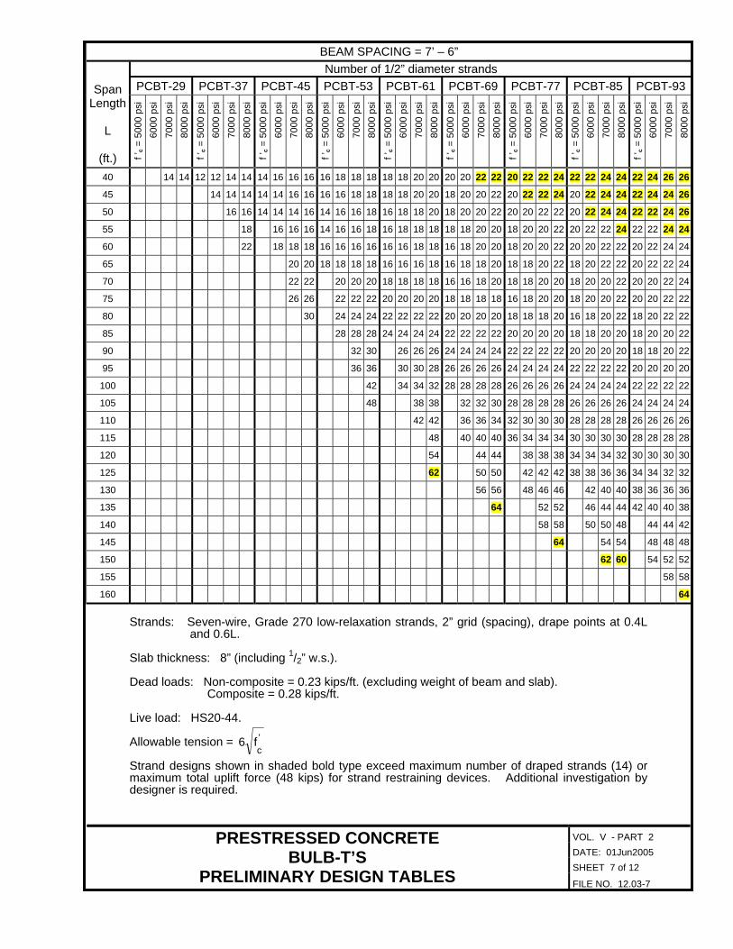
BEAM SPACING = 7’ – 6” Number of 1/2” diameter strands
PCBT-29 PCBT-37 PCBT-45 PCBT-53 PCBT-61 PCBT-69 PCBT-77 PCBT-85 PCBT-93Span Length
L
(ft.) f ’c =
500
0 ps
i 60
00 p
si
7000
psi
80
00 p
si
f ’c =
500
0 ps
i 60
00 p
si
7000
psi
80
00 p
si
f ’c =
500
0 ps
i 60
00 p
si
7000
psi
80
00 p
si
f ’c =
500
0 ps
i 60
00 p
si
7000
psi
80
00 p
si
f ’c =
500
0 ps
i 60
00 p
si
7000
psi
80
00 p
si
f ’c =
500
0 ps
i 60
00 p
si
7000
psi
80
00 p
si
f ’c =
500
0 ps
i 60
00 p
si
7000
psi
80
00 p
si
f ’c =
500
0 ps
i 60
00 p
si
7000
psi
80
00 p
si
f ’c =
500
0 ps
i 60
00 p
si
7000
psi
80
00 p
si
40 14 14 12 12 14 14 14 16 16 16 16 18 18 18 18 18 20 20 20 20 22 22 20 22 22 24 22 22 24 24 22 24 26 26
45 14 14 14 14 14 16 16 16 16 18 18 18 18 20 20 18 20 20 22 20 22 22 24 20 22 24 24 22 24 24 26
50 16 16 14 14 14 16 14 16 16 18 16 18 18 20 18 20 20 22 20 20 22 22 20 22 24 24 22 22 24 26
55 18 16 16 16 14 16 16 18 16 18 18 18 18 18 20 20 18 20 20 22 20 22 22 24 22 22 24 24
60 22 18 18 18 16 16 16 16 16 16 18 18 16 18 20 20 18 20 20 22 20 20 22 22 20 22 24 24
65 20 20 18 18 18 18 16 16 16 18 16 18 18 20 18 18 20 22 18 20 22 22 20 22 22 24
70 22 22 20 20 20 18 18 18 18 16 16 18 20 18 18 20 20 18 20 20 22 20 20 22 24
75 26 26 22 22 22 20 20 20 20 18 18 18 18 16 18 20 20 18 20 20 22 20 20 22 22
80 30 24 24 24 22 22 22 22 20 20 20 20 18 18 18 20 16 18 20 22 18 20 22 22
85 28 28 28 24 24 24 24 22 22 22 22 20 20 20 20 18 18 20 20 18 20 20 22
90 32 30 26 26 26 24 24 24 24 22 22 22 22 20 20 20 20 18 18 20 22
95 36 36 30 30 28 26 26 26 26 24 24 24 24 22 22 22 22 20 20 20 20
100 42 34 34 32 28 28 28 28 26 26 26 26 24 24 24 24 22 22 22 22
105 48 38 38 32 32 30 28 28 28 28 26 26 26 26 24 24 24 24
110 42 42 36 36 34 32 30 30 30 28 28 28 28 26 26 26 26
115 48 40 40 40 36 34 34 34 30 30 30 30 28 28 28 28
120 54 44 44 38 38 38 34 34 34 32 30 30 30 30
125 62 50 50 42 42 42 38 38 36 36 34 34 32 32
130 56 56 48 46 46 42 40 40 38 36 36 36
135 64 52 52 46 44 44 42 40 40 38
140 58 58 50 50 48 44 44 42
145 64 54 54 48 48 48
150 62 60 54 52 52
155 58 58
160 64 Strands: Seven-wire, Grade 270 low-relaxation strands, 2” grid (spacing), drape points at 0.4L
and 0.6L. Slab thickness: 8” (including 1/2” w.s.). Dead loads: Non-composite = 0.23 kips/ft. (excluding weight of beam and slab).
Composite = 0.28 kips/ft. Live load: HS20-44. Allowable tension = '
cf6
Strand designs shown in shaded bold type exceed maximum number of draped strands (14) or maximum total uplift force (48 kips) for strand restraining devices. Additional investigation by designer is required.
DATE: 01Jun2005 SHEET 7 of 12
PRESTRESSED CONCRETE BULB-T’S
PRELIMINARY DESIGN TABLES FILE NO. 12.03-7

VOL. V - PART 2
BEAM SPACING = 8’ – 0” Number of 1/2” diameter strands
PCBT-29 PCBT-37 PCBT-45 PCBT-53 PCBT-61 PCBT-69 PCBT-77 PCBT-85 PCBT-93Span Length
L
(ft.) f ’c =
500
0 ps
i 60
00 p
si
7000
psi
80
00 p
si
f ’c =
500
0 ps
i 60
00 p
si
7000
psi
80
00 p
si
f ’c =
500
0 ps
i 60
00 p
si
7000
psi
80
00 p
si
f ’c =
500
0 ps
i 60
00 p
si
7000
psi
80
00 p
si
f ’c =
500
0 ps
i 60
00 p
si
7000
psi
80
00 p
si
f ’c =
500
0 ps
i 60
00 p
si
7000
psi
80
00 p
si
f ’c =
500
0 ps
i 60
00 p
si
7000
psi
80
00 p
si
f ’c =
500
0 ps
i 60
00 p
si
7000
psi
80
00 p
si
f ’c =
500
0 ps
i 60
00 p
si
7000
psi
80
00 p
si
40 14 12 14 14 14 16 16 18 16 18 18 20 18 18 20 22 20 20 22 22 20 22 24 24 22 24 24 26 24 24 26 26
45 14 14 14 14 14 16 16 16 16 18 18 18 18 20 20 18 20 20 22 20 22 22 24 22 22 24 26 22 24 26 26
50 16 14 14 14 16 14 16 16 18 16 18 18 20 18 20 20 22 20 20 22 22 20 22 24 24 22 24 24 26
55 20 16 16 16 14 14 16 18 16 18 18 20 18 18 20 20 18 20 22 22 20 22 22 24 22 22 24 26
60 18 18 16 16 18 14 16 18 18 16 18 20 20 18 20 20 22 20 20 22 24 20 22 24 24
65 22 22 18 18 18 16 16 16 18 16 18 18 20 18 18 20 22 18 20 22 22 20 22 22 24
70 24 20 20 20 18 18 18 18 16 16 18 20 16 18 20 20 18 20 22 22 20 22 22 24
75 26 24 24 24 20 20 20 20 18 18 18 18 18 18 18 20 18 20 20 22 20 20 22 24
80 26 26 22 22 22 20 20 20 20 18 18 18 20 18 18 20 22 18 20 22 22
85 28 26 26 26 22 22 22 22 20 20 20 20 20 20 20 20 18 18 20 22
90 34 28 28 28 26 26 26 26 22 22 22 22 22 22 22 22 20 20 20 22
95 38 32 30 28 28 28 28 26 26 26 26 24 24 24 24 22 22 22 22
100 36 36 30 30 30 28 28 28 28 26 26 26 26 24 24 24 24
105 40 34 34 34 30 30 30 30 28 28 28 28 26 26 26 26
110 46 38 38 38 34 32 32 30 30 30 30 28 28 28 28
115 52 44 42 38 36 36 34 32 32 32 30 30 30 30
120 48 48 42 40 40 36 36 36 34 32 32 32 32
125 54 46 46 44 40 40 38 36 36 34 34
130 62 50 50 44 44 44 40 40 38 38
135 56 56 50 48 48 44 42 42
140 64 54 52 48 46 46
145 60 58 52 52 50
150 66 58 56
155 64 62
160 72 Strands: Seven-wire, Grade 270 low-relaxation strands, 2” grid (spacing), drape points at 0.4L
and 0.6L. Slab thickness: 81/2” (including 1/2” w.s.). Dead loads: Non-composite = 0.24 kips/ft. (excluding weight of beam and slab).
Composite = 0.29 kips/ft. Live load: HS20-44. Allowable tension = '
cf6
Strand designs shown in shaded bold type exceed maximum number of draped strands (14) or maximum total uplift force (48 kips) for strand restraining devices. Additional investigation by designer is required.
DATE: 01Jun2005 SHEET 8 of 12
PRESTRESSED CONCRETE BULB-T’S
PRELIMINARY DESIGN TABLES FILE NO. 12.03-8
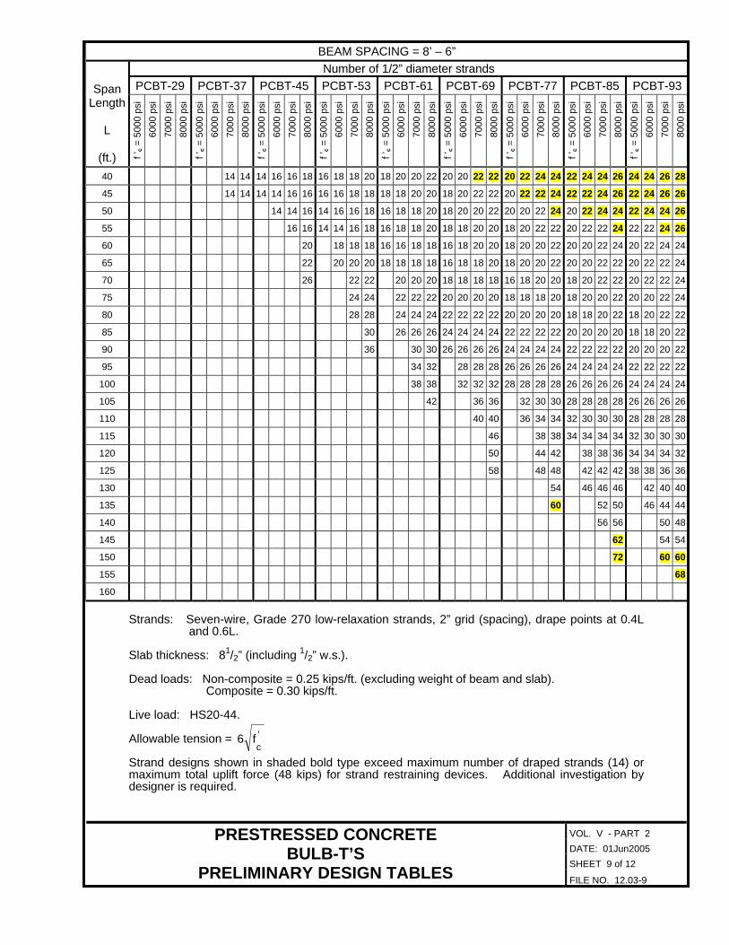
VOL. V - PART 2
BEAM SPACING = 8’ – 6” Number of 1/2” diameter strands
PCBT-29 PCBT-37 PCBT-45 PCBT-53 PCBT-61 PCBT-69 PCBT-77 PCBT-85 PCBT-93Span Length
L
(ft.) f ’c =
500
0 ps
i 60
00 p
si
7000
psi
80
00 p
si
f ’c =
500
0 ps
i 60
00 p
si
7000
psi
80
00 p
si
f ’c =
500
0 ps
i 60
00 p
si
7000
psi
80
00 p
si
f ’c =
500
0 ps
i 60
00 p
si
7000
psi
80
00 p
si
f ’c =
500
0 ps
i 60
00 p
si
7000
psi
80
00 p
si
f ’c =
500
0 ps
i 60
00 p
si
7000
psi
80
00 p
si
f ’c =
500
0 ps
i 60
00 p
si
7000
psi
80
00 p
si
f ’c =
500
0 ps
i 60
00 p
si
7000
psi
80
00 p
si
f ’c =
500
0 ps
i 60
00 p
si
7000
psi
80
00 p
si
40 14 14 14 16 16 18 16 18 18 20 18 20 20 22 20 20 22 22 20 22 24 24 22 24 24 26 24 24 26 28
45 14 14 14 14 16 16 16 16 18 18 18 18 20 20 18 20 22 22 20 22 22 24 22 22 24 26 22 24 26 26
50 14 14 16 14 16 16 18 16 18 18 20 18 20 20 22 20 20 22 24 20 22 24 24 22 24 24 26
55 16 16 14 14 16 18 16 18 18 20 18 18 20 20 18 20 22 22 20 22 22 24 22 22 24 26
60 20 18 18 18 16 16 18 18 16 18 20 20 18 20 20 22 20 20 22 24 20 22 24 24
65 22 20 20 20 18 18 18 18 16 18 18 20 18 20 20 22 20 20 22 22 20 22 22 24
70 26 22 22 20 20 20 18 18 18 18 16 18 20 20 18 20 22 22 20 22 22 24
75 24 24 22 22 22 20 20 20 20 18 18 18 20 18 20 20 22 20 20 22 24
80 28 28 24 24 24 22 22 22 22 20 20 20 20 18 18 20 22 18 20 22 22
85 30 26 26 26 24 24 24 24 22 22 22 22 20 20 20 20 18 18 20 22
90 36 30 30 26 26 26 26 24 24 24 24 22 22 22 22 20 20 20 22
95 34 32 28 28 28 26 26 26 26 24 24 24 24 22 22 22 22
100 38 38 32 32 32 28 28 28 28 26 26 26 26 24 24 24 24
105 42 36 36 32 30 30 28 28 28 28 26 26 26 26
110 40 40 36 34 34 32 30 30 30 28 28 28 28
115 46 38 38 34 34 34 34 32 30 30 30
120 50 44 42 38 38 36 34 34 34 32
125 58 48 48 42 42 42 38 38 36 36
130 54 46 46 46 42 40 40
135 60 52 50 46 44 44
140 56 56 50 48
145 62 54 54
150 72 60 60
155 68
160
Strands: Seven-wire, Grade 270 low-relaxation strands, 2” grid (spacing), drape points at 0.4L
and 0.6L. Slab thickness: 81/2” (including 1/2” w.s.). Dead loads: Non-composite = 0.25 kips/ft. (excluding weight of beam and slab).
Composite = 0.30 kips/ft. Live load: HS20-44. Allowable tension = '
cf6
Strand designs shown in shaded bold type exceed maximum number of draped strands (14) or maximum total uplift force (48 kips) for strand restraining devices. Additional investigation by designer is required.
DATE: 01Jun2005 SHEET 9 of 12
PRESTRESSED CONCRETE BULB-T’S
PRELIMINARY DESIGN TABLES FILE NO. 12.03-9

VOL. V - PART 2
BEAM SPACING = 9’ – 0” Number of 1/2” diameter strands
PCBT-29 PCBT-37 PCBT-45 PCBT-53 PCBT-61 PCBT-69 PCBT-77 PCBT-85 PCBT-93Span Length
L
(ft.) f ’c =
500
0 ps
i 60
00 p
si
7000
psi
80
00 p
si
f ’c =
500
0 ps
i 60
00 p
si
7000
psi
80
00 p
si
f ’c =
500
0 ps
i 60
00 p
si
7000
psi
80
00 p
si
f ’c =
500
0 ps
i 60
00 p
si
7000
psi
80
00 p
si
f ’c =
500
0 ps
i 60
00 p
si
7000
psi
80
00 p
si
f ’c =
500
0 ps
i 60
00 p
si
7000
psi
80
00 p
si
f ’c =
500
0 ps
i 60
00 p
si
7000
psi
80
00 p
si
f ’c =
500
0 ps
i 60
00 p
si
7000
psi
80
00 p
si
f ’c =
500
0 ps
i 60
00 p
si
7000
psi
80
00 p
si
40 14 14 14 16 16 18 16 18 18 20 18 20 20 22 20 20 22 22 20 22 24 24 22 24 24 26 24 24 26 28
45 14 16 16 16 16 18 18 18 18 20 20 18 20 22 22 20 22 22 24 22 22 24 26 22 24 26 26
50 16 16 14 16 16 18 16 18 18 20 18 20 20 22 20 20 22 24 20 22 24 24 22 24 24 26
55 18 16 16 16 16 16 18 18 18 18 20 20 18 20 22 22 20 22 22 24 22 22 24 26
60 20 18 18 16 16 18 18 16 18 20 20 18 20 20 22 20 20 22 24 20 22 24 24
65 24 20 20 18 18 18 16 18 18 20 18 18 20 22 18 20 22 22 20 22 22 24
70 22 22 20 20 20 18 18 18 18 16 18 20 20 18 20 22 22 20 22 22 24
75 26 26 22 22 22 20 20 20 20 18 18 18 20 18 20 20 22 18 20 22 24
80 28 26 26 26 22 22 22 20 20 20 20 20 20 20 22 18 20 22 22
85 28 28 24 24 24 22 22 22 22 20 20 20 20 20 20 20 22
90 30 28 28 28 24 24 24 24 22 22 22 22 22 22 22 22
95 34 30 30 28 28 28 28 26 26 26 26 24 24 24 24
100 34 32 30 30 30 28 28 28 28 26 26 26 26
105 38 38 32 32 32 30 30 30 28 28 28 28
110 42 36 36 36 32 32 32 30 30 30 30
115 48 40 40 36 36 34 32 32 32 32
120 46 46 40 40 38 36 36 34 34
125 50 44 44 40 38 38
130 56 48 48 44 42 42
135 54 48 48 46
140 60 52 52
145 68 58 56
150 64
155 72
160
Strands: Seven-wire, Grade 270 low-relaxation strands, 2” grid (spacing), drape points at 0.4L
and 0.6L. Slab thickness: 81/2” (including 1/2” w.s.). Dead loads: Non-composite = 0.26 kips/ft. (excluding weight of beam and slab).
Composite = 0.31 kips/ft. Live load: HS20-44. Allowable tension = '
cf6
Strand designs shown in shaded bold type exceed maximum number of draped strands (14) or maximum total uplift force (48 kips) for strand restraining devices. Additional investigation by designer is required.
DATE: 01Jun2005 SHEET 10 of 12
PRESTRESSED CONCRETE BULB-T’S
PRELIMINARY DESIGN TABLES FILE NO. 12.03-10

VOL. V - PART 2
BEAM SPACING = 9’ – 6” Number of 1/2” diameter strands
PCBT-29 PCBT-37 PCBT-45 PCBT-53 PCBT-61 PCBT-69 PCBT-77 PCBT-85 PCBT-93Span Length
L
(ft.) f ’c =
500
0 ps
i 60
00 p
si
7000
psi
80
00 p
si
f ’c =
500
0 ps
i 60
00 p
si
7000
psi
80
00 p
si
f ’c =
500
0 ps
i 60
00 p
si
7000
psi
80
00 p
si
f ’c =
500
0 ps
i 60
00 p
si
7000
psi
80
00 p
si
f ’c =
500
0 ps
i 60
00 p
si
7000
psi
80
00 p
si
f ’c =
500
0 ps
i 60
00 p
si
7000
psi
80
00 p
si
f ’c =
500
0 ps
i 60
00 p
si
7000
psi
80
00 p
si
f ’c =
500
0 ps
i 60
00 p
si
7000
psi
80
00 p
si
f ’c =
500
0 ps
i 60
00 p
si
7000
psi
80
00 p
si
40 14 16 16 16 16 18 18 20 18 18 20 22 20 20 22 22 20 22 24 24 22 24 24 26 24 24 26 28
45 14 16 16 16 18 18 18 18 20 20 18 20 20 22 20 22 22 24 22 22 24 26 22 24 26 26
50 16 14 16 16 18 16 18 18 20 18 20 20 22 20 20 22 22 20 22 24 24 22 24 24 26
55 18 16 16 16 16 18 18 18 18 20 20 18 20 22 22 20 22 22 24 22 22 24 26
60 18 18 16 18 18 16 18 18 20 18 20 20 22 20 20 22 24 20 22 24 24
65 22 22 18 18 18 16 18 18 20 18 18 20 22 18 20 22 22 20 22 22 24
70 24 22 22 22 20 20 20 20 18 18 20 20 18 20 20 22 20 20 22 24
75 26 24 24 22 22 22 20 20 20 20 18 18 20 22 18 20 22 22
80 26 26 24 24 24 22 22 22 22 20 20 20 20 18 20 22 22
85 28 28 26 26 26 24 24 24 24 22 22 22 22 20 20 20 22
90 32 28 28 28 26 26 26 26 24 24 24 24 22 22 22 22
95 36 32 32 28 28 28 26 26 26 26 24 24 24 24
100 36 34 30 30 28 28 28 28 26 26 26 26
105 40 34 34 30 30 30 28 28 28 28
110 44 38 38 34 34 34 30 30 30 30
115 44 42 38 38 36 34 32 32
120 48 42 40 38 36 36
125 54 46 46 42 40 40
130 50 46 44 44
135 56 50 48
140 64 54 54
145 60
150 68
155
160
Strands: Seven-wire, Grade 270 low-relaxation strands, 2” grid (spacing), drape points at 0.4L
and 0.6L. Slab thickness: 81/2” (including 1/2” w.s.). Dead loads: Non-composite = 0.27 kips/ft. (excluding weight of beam and slab).
Composite = 0.31 kips/ft. Live load: HS20-44. Allowable tension = '
cf6
Strand designs shown in shaded bold type exceed maximum number of draped strands (14) or maximum total uplift force (48 kips) for strand restraining devices. Additional investigation by designer is required.
DATE: 01Jun2005 SHEET 11 of 12
PRESTRESSED CONCRETE BULB-T’S
PRELIMINARY DESIGN TABLES FILE NO. 12.03-11
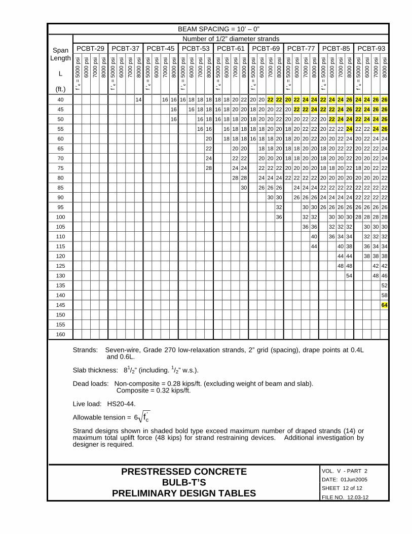
VOL. V - PART 2
BEAM SPACING = 10’ – 0” Number of 1/2” diameter strands
PCBT-29 PCBT-37 PCBT-45 PCBT-53 PCBT-61 PCBT-69 PCBT-77 PCBT-85 PCBT-93Span Length
L
(ft.) f ’c =
500
0 ps
i 60
00 p
si
7000
psi
80
00 p
si
f ’c =
500
0 ps
i 60
00 p
si
7000
psi
80
00 p
si
f ’c =
500
0 ps
i 60
00 p
si
7000
psi
80
00 p
si
f ’c =
500
0 ps
i 60
00 p
si
7000
psi
80
00 p
si
f ’c =
500
0 ps
i 60
00 p
si
7000
psi
80
00 p
si
f ’c =
500
0 ps
i 60
00 p
si
7000
psi
80
00 p
si
f ’c =
500
0 ps
i 60
00 p
si
7000
psi
80
00 p
si
f ’c =
500
0 ps
i 60
00 p
si
7000
psi
80
00 p
si
f ’c =
500
0 ps
i 60
00 p
si
7000
psi
80
00 p
si
40 14 16 16 16 18 18 18 18 18 20 22 20 20 22 22 20 22 24 24 22 24 24 26 24 24 26 26
45 16 16 18 18 16 18 20 20 18 20 20 22 20 22 22 24 22 22 24 26 22 24 26 26
50 16 16 18 16 18 18 20 18 20 20 22 20 20 22 22 20 22 24 24 22 24 24 26
55 16 16 16 18 18 18 18 20 20 18 20 22 22 20 22 22 24 22 22 24 26
60 20 18 18 18 16 18 18 20 18 20 20 22 20 20 22 24 20 22 24 24
65 22 20 20 18 18 20 18 18 20 20 18 20 22 22 20 22 22 24
70 24 22 22 20 20 20 18 18 20 20 18 20 20 22 20 20 22 24
75 28 24 24 22 22 22 20 20 20 20 18 18 20 22 18 20 22 22
80 28 28 24 24 24 22 22 22 22 20 20 20 20 20 20 20 22
85 30 26 26 26 24 24 24 22 22 22 22 22 22 22 22
90 30 30 26 26 26 24 24 24 24 22 22 22 22
95 32 30 30 26 26 26 26 26 26 26 26
100 36 32 32 30 30 30 28 28 28 28
105 36 36 32 32 32 30 30 30
110 40 36 34 34 32 32 32
115 44 40 38 36 34 34
120 44 44 38 38 38
125 48 48 42 42
130 54 48 46
135 52
140 58
145 64
150
155
160
Strands: Seven-wire, Grade 270 low-relaxation strands, 2” grid (spacing), drape points at 0.4L
and 0.6L. Slab thickness: 81/2” (including. 1/2” w.s.). Dead loads: Non-composite = 0.28 kips/ft. (excluding weight of beam and slab).
Composite = 0.32 kips/ft. Live load: HS20-44. Allowable tension = '
cf6 Strand designs shown in shaded bold type exceed maximum number of draped strands (14) or maximum total uplift force (48 kips) for strand restraining devices. Additional investigation by designer is required.
DATE: 01Jun2005 SHEET 12 of 12
PRESTRESSED CONCRETE BULB-T’S
PRELIMINARY DESIGN TABLES FILE NO. 12.03-12