Pre-Procedural Preparation and CRT Implantation Tips and Tricks
86
Pre-Procedural Preparation and CRT Implantation Tips and Tricks THRS CIED PHYSICIAN TRAINING COURSE Part III: CRT 19, Jun, 2016 Yung-Lung, Chen M.D.
-
Upload
taiwan-heart-rhythm-society -
Category
Devices & Hardware
-
view
357 -
download
0
Transcript of Pre-Procedural Preparation and CRT Implantation Tips and Tricks

Pre-Procedural Preparation
and CRT Implantation
Tips and Tricks
THRS CIED PHYSICIAN TRAINING COURSE
Part III: CRT
19, Jun, 2016
Yung-Lung, Chen M.D.

Outlines
Pre-Procedural Preparation
CRT Implantation Tips and
Tricks

Outlines
Pre-Procedural Preparation
CRT Implantation Tips and
Tricks

Pre-Procedure preparation

Pre-Procedure preparation
Baseline clinical data
Image techniques
Electrical assessment (resting ECG)
Pre-implantation medical management

Baseline clinical data
Optimal medical management stable for at least 3 months before implant
Routine laboratory/biomarker
evaluation BNP/NT-proBNP
Growth differentiation factor-15; amino-terminal propeptide type III procollagen
Functional assessment
6 minutes hall walk test
CPET/ peak O2 consumption

Baseline clinical data
Quality of life measurements
The Minnesota Living with HF questionnaire
Determination of heart failure
aetiology/coronary angiography
Comorbidities/life expectancy
the Seattle heart failure model (SHFM)
Charlson comorbidity index
Non-ambulatory New York Heart
Association class IV
inotropic support/ beta-blocker intolerance
bail-out / last resort therapy

Image techniques
Basic anatomical and functional measures
Dyssynchrony evaluation by imaging/
echocardiography
Cardiac CTA and cardiac MRI
Cardiac CTA and cardiac MRI to define coronary
venous anatomy
Ventricular function and tissue characteristics
CTA: computed tomography angiography
MRI: magnetic resonance imaging

Electrical assessment:
resting ECG
P-wave and atrial rhythm
PR interval
QRS complex duration and morphology
ECG criteria for LBBB revisited
QT interval
Premature ventricular contractions
Additional electrophysiological
measurements (electroanatomic mapping)

Pre-implantation medical
management
Antithrombotics
bridging heparin abandoned
(12-20% pocket haepatoma)
low to moderate thromboembolic risk
(biologic valve, Afib. with CHADS2 score < 4,
no history of thromboembolic event)
PT INR 1.5-2.5 x or stop for 3-5 days VKA;
NOACs stop 2-3 days
Re-on the secondary day
aspirin or dual antiplatelet 2-4x risk (3.9-7.2% v.s. 1.6%)
primary prevention, low risk, high risk

KCGMH data
Can J Cardiol. 2013 Sep;29(9):1110-7.

Pre-implantation medical
management
Antibiotics
Multicenter registry(6319pts/44H):0.68%/1yr
Risks: temporary pacing or other procedures, early reintervention and without antibiotic prophylaxis.
DBRT: 3.28%0.63% 1gm cefazolin iv.
Peri-OP antibiotics: cefazolin 1 hr before
vancomycin 2 hr before
Contrast induced nephrotoxicity
Hydration; acetylcysteineDBRT: Double blind-randomized trial

Outlines
Pre-Procedural Preparation
CRT Implantation Tips and
Tricks

Steps in CRT Implantation
Pre-implant preparation
CXR / Implant setup and tools
PPM wound prepare
Venography/Venous access
RV lead position
Cannulate coronary sinus
Perform CS venograms
Select target vein and leads
Place leads
Measure final parameters
Remove implant tools
Program CRT devices

Steps in CRT Implantation
CXR / Implant setup and tools
PPM wound prepare
Venography/Venous access
RV lead position
Cannulate coronary sinus
Perform CS venograms
Select target vein and leads
Place leads
Measure final electricals
Remove implant tools

CXR

CS Cannulation Catheters
Metronic

Steps in CRT Implantation
CXR / Implant setup and tools
PPM wound prepare
Venography/Venous access
RV lead position
Cannulate coronary sinus
Perform CS venograms
Select target vein and leads
Place leads
Measure final electricals
Remove implant tools

PPM wound area prepare

Steps in CRT Implantation
CXR / Implant setup and tools
PPM wound prepare
Venography/Venous access
RV lead position
Cannulate coronary sinus
Perform CS venograms
Select target vein and leads
Place leads
Measure final electricals
Remove implant tools

Venography

Venous access
Preferably start from left site
Preferably use 3 or 2 different access
points to reduce friction
o Always use separate access point for
LV lead

Cut-down or Puncture

Cut-down or Puncture

Steps in CRT Implantation
CXR / Implant setup and tools
PPM wound prepare
Venography/Venous access
Order of lead placement/RV lead position
Cannulate coronary sinus
Perform CS venograms
Select target vein and leads
Place leads
Measure final electricals
Remove implant tools

Order of lead placement
PRO CON
LV Lead
Placed
FIRST
1. No interference from other
leads being in the way
2. May save time & money
1. Other means
of back-up
pacing
RV Lead
Placed
FIRST
1. Back up pacing
2. Idea of RA dimension &
general cardiac anatomy
1. May get in way
of LV sheath

Position of RV lead
Optimal site still not determined
Mid septal or RVOT preferred by some
However DFT may be higher

Steps in CRT Implantation
CXR / Implant setup and tools
PPM wound prepare
Venography/Venous access
RV lead position
Cannulate coronary sinus
Perform CS venograms
Select target vein and leads
Place leads
Measure final electricals
Remove implant tools

Burkhardt, J. D. et al. Circulation 2007;115:2208-2220
Right atrial anatomy and
relationship to coronary sinus

Cannulating Coronary OS
Key points in the anatomy of the
CS ostium (OS)
o The OS is in the posteroseptal region
of the RA & may be obstructed by
Thebesian valve
o The OS is not on the floor of the RA,
but up 1 to 2 cm
o As the RA dilates the OS may be
more posterior and ~1 cm higher

Effect of CCWR rotation
First moves to the left
Then, moves downwards
Start here
From: Clinical Cardiac Pacing, Defibrillation and CRT by Ellenbogen

Effect of CCWR rotation
Staring too low
From: Clinical Cardiac Pacing, Defibrillation and CRT by Ellenbogen

Cannulating Coronary OS:
From below

Cannulating Coronary OS:
From above

Cannulation of CS OS
Materials used:
Outer Guide Catheter
Guidewire
EP catheter
Coronary catheter (JR, AL)
Inner sheath (Cannulators)

Cannulating Coronary OS:
Our Way

Cannulating Coronary OS:
Our Way

Cannulating Coronary Os:
EP approach
Cannulation_Method3-EP_Approach.wmv

Cannulation of CS OS
IEGM to confirm position
A / V > 1
Atrial signal at the end of the P-wave

Tips to advance sheath in CS
A guidewire can
be used to guide
the sheet
First advance the
EP catheter or
Cannulator (inner
sheath) over the
guide
Advance the outer
sheath Direct
From: Clinical Cardiac Pacing, Defibrillation and CRT by Ellenbogen

Steps in CRT Implantation
CXR / Implant setup and tools
PPM wound prepare
Venography/Venous access
RV lead position
Cannulate coronary sinus
Perform CS venograms
Select target vein and leads
Place leads
Measure final electricals
Remove implant tools

Coronary venogram
• Flush balloon catheter prior to
use.
• Test the balloon in a basin of
saline prior to insertion to
determine the volume of air
required for inflation, and to
insure that no air embolus will
be introduced.
• Always use the manufacture's
syringe to inflate the balloon

Performing venogram
• Inject contrast in order to verify
location, thereafter inflate the balloon.
• Do not use to much pressure.
• See to that the catheter tip is not blocked
against the vein wall.
• Avoid inflating the balloon where it
possible could damage the vein
• insure that a dissection has not taken
place prior to balloon inflation
• Give an initial gentle puff of contrast
before inflating the balloon to verify
proper positioning within the CS,
thus preventing dissection or staining.

Coronary venography

Coronary vein

LV lead position: lessons
from MADIT-CRT
Circulation March 22, 2011
Conclusion: LV leads positioned in the apical region were
associated with an unfavorable outcome, suggesting that this
lead location should be avoided in cardiac resynchronization
therapy

Selecting target vein
size
angulation
tortuosity

Occlusive Coronary
Venogram
Always 3 views: AP-LAO-RAO
AP, RAO and LAO show different onset of the target vein
From: Clinical Cardiac Pacing, Defibrillation and CRT by Ellenbogen
RAOLAO

Quadripolar vs Bipolar leads

LV leads-SJM
Lead Lead
body size
Polarity
QuickFlex
1258T
4.3Fr Bipolar
Quartet
1458T
4.7 Fr Quadripol
ar

LV Lead-Medtronic
Leads Lead Body Size Polarity
Attain® OTW
Model 4193
4 Fr (1.3 mm) Unipolar
Attain OTW
Model 4194
6.2 Fr (2.0 mm) True
bipolar
Attain Starfix
Model 4195
5 Fr (1.7 mm) Unipolar
Attain Ability
Model 4196
4 Fr (1.3 mm) Bipolar
(dual
electrode)
Attain Performa 5.3Fr Quadripola
r

Steps in CRT Implantation
CXR / Implant setup and tools
PPM wound prepare
Venography/Venous access
RV lead position
Cannulate coronary sinus
Perform CS venograms
Select target vein and leads
Place leads
Measure final electricals
Remove implant tools

Handling options to suit your technique
Over-the-wire or stylet-driven design allows use of either a
stylet or guidewire
Guidewire can be either front-loaded or back-loaded
You need a separate 0.014” guidewire (not in the package)
Guidewire or stylet

Lead position

Best site to pace LV
Anatomical – lateral vein
Fluroscopy – RV and LV lead tip as far apart
anatomically as possible
Electrogram – LV egm at late in QRS as possible, RV
and LV electrogram as far apart as possible
Hemodynamic – best dP/dt, pulse pressure
ECG – QRS narrowing during pacing
Latest area of mechanical activation as determined by
imaging tools – eg echo, MRI,

Final positioning
RAO LAO

Lead Delivery
Electrical Measurements
o Threshold
o Sensing amplitude / separation Goal of at least 100 msec between RV and LV senses.
o Nervus Phrenicus stimulation

Best site to pace LV
Anatomical – lateral vein
Fluroscopy – RV and LV lead tip as far apart
anatomically as possible
Electrogram – LV egm at late in QRS as possible, RV
and LV electrogram as far apart as possible
Hemodynamic – best dP/dt, pulse pressure
ECG – QRS narrowing during pacing
Latest area of mechanical activation as determined by
imaging tools – eg echo, MRI,

LV electrical lead position
SR, LBBB, QRS: 189 ms
LAO
50°
His
Bundle
RAO
30°
Earliest Ventricular
Activation
LAO
90°
Latest Ventricular
Activated Region

Sites to avoid
Anterior (GCV) pacing
Apical LV lead position
Phrenic nerve stimulation
Scar areas

Steps in CRT Implantation
CXR / Implant setup and tools
PPM wound prepare
Venography/Venous access
RV lead position
Cannulate coronary sinus
Perform CS venograms
Select target vein and leads
Place leads
Measure final parameters
Remove implant tools

Electrical Measurements
Electrical Measurements
o Threshold (< 3 V)
o Sensing amplitude / separation
o Impedence (mid-range of
manufacturer’s specifications)
o Nervus Phrenicus stimulation (10 V)

Real Case (1)

Real Case (2)

Real Case (3)

Real Case (4)

Real Case (5)

Steps in CRT Implantation
CXR / Implant setup and tools
PPM wound prepare
Venography/Venous access
RV lead position
Cannulate coronary sinus
Perform CS venograms
Select target vein and leads
Place leads
Measure final parameters
Remove implant tools
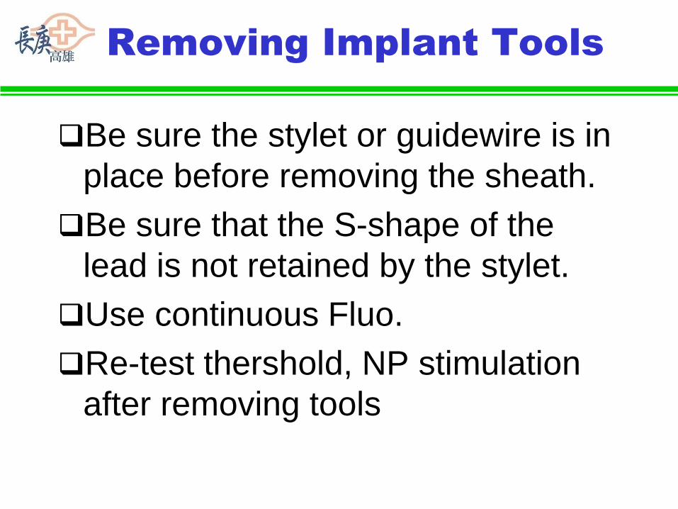
Removing Implant Tools
Be sure the stylet or guidewire is in
place before removing the sheath.
Be sure that the S-shape of the
lead is not retained by the stylet.
Use continuous Fluo.
Re-test thershold, NP stimulation
after removing tools

Removing Implant Tools

76
Snap lead into lead
channel of slitter

77
Slitting

78
Incorrect Slitting

79
Correct Slitting

80
Incorrect Slitting

Fixating the leads

Connect CRT devices
CRT-PCRT-D

IS4 & DF4 Connector Pin Differences
Lead Connector dimensions are the same except for the pin
DF4-LLHH
IS4-LLLL
Pin is steps down to
a smaller diameter
Pin is larger
diameter & does
NOT step down

Thanks for your attention!!

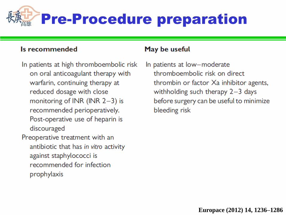
Pre-Procedure preparation
Europace (2012) 14, 1236–1286

Pre-Procedure preparation
Europace (2012) 14, 1236–1286
Pre-Procedure preparation
Europace (2012) 14, 1236–1286

Methods of patient assessment
prior to CRT implant
Europace (2012) 14, 1236–1286
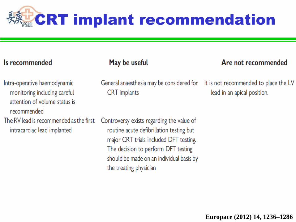
CRT implant recommendation
Europace (2012) 14, 1236–1286

CRT implant recommendation
Europace (2012) 14, 1236–1286