
Pre-installation Planning Guide for Cisco Unified ICM Enterprise and ...
127
Pre-installation Planning Guide for Cisco Unified ICM Enterprise and Hosted Release 8.0( 1) February 2010 Americas Headquarters Cisco Systems, Inc. 170 West Tasman Drive San Jose, CA 95134-1706 USA http://www.cisco.com Tel: 408 526-4000 800 553-NETS (6387) Fax: 408 527-0833
-
Upload
nguyenliem -
Category
Documents
-
view
233 -
download
1
Transcript of Pre-installation Planning Guide for Cisco Unified ICM Enterprise and ...

Pre-installation Planning Guide
for Cisco Unified ICM Enterprise and HostedRelease 8.0( 1)
February 2010
Americas Headquarters
Cisco Systems, Inc.
170 West Tasman Drive
San Jose, CA 95134-1706
USA
http://www.cisco.com
Tel: 408 526-4000
800 553-NETS (6387)
Fax: 408 527-0833

THE SPECIFICATIONS AND INFORMATION REGARDING THE PRODUCTS IN THIS MANUAL ARE SUBJECT TO CHANGE WITHOUT NOTICE.ALL STATEMENTS, INFORMATION, AND RECOMMENDATIONS IN THIS MANUAL ARE BELIEVED TO BE ACCURATE BUT ARE PRESENTEDWITHOUT WARRANTY OF ANY KIND, EXPRESS OR IMPLIED. USERS MUST TAKE FULL RESPONSIBILITY FOR THEIR APPLICATION OFANY PRODUCTS.THE SOFTWARE LICENSE AND LIMITED WARRANTY FOR THE ACCOMPANYING PRODUCT ARE SET FORTH IN THE INFORMATION PACKETTHAT SHIPPED WITH THE PRODUCT AND ARE INCORPORATED HEREIN BY THIS REFERENCE. IF YOU ARE UNABLE TO LOCATE THESOFTWARE LICENSE OR LIMITED WARRANTY, CONTACT YOUR CISCO REPRESENTATIVE FOR A COPY.The Cisco implementation of TCP header compression is an adaptation of a program developed by the University of California, Berkeley (UCB) aspart of UCBs public domain version of the UNIX operating system. All rights reserved. Copyright 1981, Regents of the University of California.NOTWITHSTANDING ANY OTHER WARRANTY HEREIN, ALL DOCUMENT FILES AND SOFTWARE OF THESE SUPPLIERS ARE PROVIDED"AS IS" WITH ALL FAULTS. CISCO AND THE ABOVE-NAMED SUPPLIERS DISCLAIM ALL WARRANTIES, EXPRESSED OR IMPLIED, INCLUDING,WITHOUT LIMITATION, THOSE OF MERCHANTABILITY, FITNESS FOR A PARTICULAR PURPOSE AND NONINFRINGEMENT OR ARISINGFROM A COURSE OF DEALING, USAGE, OR TRADE PRACTICE.IN NO EVENT SHALL CISCO OR ITS SUPPLIERS BE LIABLE FOR ANY INDIRECT, SPECIAL, CONSEQUENTIAL, OR INCIDENTAL DAMAGES,INCLUDING, WITHOUT LIMITATION, LOST PROFITS OR LOSS OR DAMAGE TO DATA ARISING OUT OF THE USE OR INABILITY TO USETHIS MANUAL, EVEN IF CISCO OR ITS SUPPLIERS HAVE BEEN ADVISED OF THE POSSIBILITY OF SUCH DAMAGES.CCDE, CCENT, CCSI, Cisco Eos, Cisco HealthPresence, Cisco IronPort, the Cisco logo, Cisco Nurse Connect, Cisco Pulse, Cisco SensorBase,Cisco StackPower, Cisco StadiumVision, Cisco TelePresence, Cisco Unified Computing System, Cisco WebEx, DCE, Flip Channels, Flip for Good,Flip Mino, Flipshare (Design), Flip Ultra, Flip Video, Flip Video (Design), Instant Broadband, and Welcome to the Human Network are trademarks;Changing the Way We Work, Live, Play, and Learn, Cisco Capital, Cisco Capital (Design), Cisco:Financed (Stylized), Cisco Store, Flip Gift Card, andOne Million Acts of Green are service marks; and Access Registrar, Aironet, AllTouch, AsyncOS, Bringing the Meeting To You, Catalyst, CCDA,CCDP, CCIE, CCIP, CCNA, CCNP, CCSP, CCVP, Cisco, the Cisco Certified Internetwork Expert logo, Cisco IOS, Cisco Lumin, Cisco Nexus, CiscoPress, Cisco Systems, Cisco Systems Capital, the Cisco Systems logo, Cisco Unity, Collaboration Without Limitation, Continuum, EtherFast, EtherSwitch,Event Center, Explorer, Follow Me Browsing, GainMaker, iLYNX, IOS, iPhone, IronPort, the IronPort logo, Laser Link, LightStream, Linksys, MeetingPlace,MeetingPlace Chime Sound, MGX, Networkers, Networking Academy, PCNow, PIX, PowerKEY, PowerPanels, PowerTV, PowerTV (Design), PowerVu,Prisma, ProConnect, ROSA, SenderBase, SMARTnet, Spectrum Expert, StackWise, WebEx, and the WebEx logo are registered trademarks of CiscoSystems, Inc. and/or its affiliates in the United States and certain other countries.All other trademarks mentioned in this document or website are the property of their respective owners. The use of the word partner does not implya partnership relationship between Cisco and any other company. (0910R)Any Internet Protocol (IP) addresses used in this document are not intended to be actual addresses. Any examples, command display output, andfigures included in the document are shown for illustrative purposes only. Any use of actual IP addresses in illustrative content is unintentional andcoincidental.Copyright 2010 Cisco Systems, Inc. All rights reserved.
Table of Contents
Preface ...........................................................................................................................................................1Purpose .....................................................................................................................................................1Audience ....................................................................................................................................................1Organization ..............................................................................................................................................1Related Documentation..............................................................................................................................2Product Naming Conventions.....................................................................................................................3Conventions................................................................................................................................................4Obtaining Documentation and Submitting a Service Request...................................................................5Documentation Feedback...........................................................................................................................5
1. Pre-installation Planning Overview.............................................................................................................7The Planning Process................................................................................................................................7
Coordinating and Scheduling Tasks.......................................................................................................7Pre-installation Document Road Map....................................................................................................8NIC and ACD Supplements...................................................................................................................9
2. Cisco Unified ICME Overview...................................................................................................................11How the ICM Software Works...................................................................................................................11
ICM Call Routing..................................................................................................................................12ICM System Components and Processes................................................................................................14
CallRouter............................................................................................................................................14Logger..................................................................................................................................................14Network Interface Controller (NIC).......................................................................................................14Peripheral Gateways............................................................................................................................15Administration & Data Server..............................................................................................................15Historical Data Server..........................................................................................................................16ICM Reporting.....................................................................................................................................16
ICM Options and Related Products..........................................................................................................17Pre-Routing..........................................................................................................................................17Post-Routing........................................................................................................................................18Pre- and Post-Routing Systems...........................................................................................................18Computer Telephony Integration (CTI).................................................................................................19IVR Interface........................................................................................................................................20ICM Application Gateway.....................................................................................................................20ICM Gateway SQL...............................................................................................................................21Internet Script Editor............................................................................................................................22ICM Multichannel Software..................................................................................................................22Cisco Unified Contact Center..............................................................................................................23
3. IXC Overview............................................................................................................................................25ICM Software and IXC Interaction............................................................................................................25
Toll-Free Caller ....................................................................................................................................26LEC-to-IXC .........................................................................................................................................26Network Query ....................................................................................................................................27ICM NIC ..............................................................................................................................................27NIC-to-CallRouter ...............................................................................................................................27Best Destination Returned ..................................................................................................................27IXC Network ........................................................................................................................................27Connecting the Call ............................................................................................................................27Carrier Connections.............................................................................................................................27
Pre-installation Planning Guide for Cisco Unified ICM Enterprise and Hosted Release 8.0( 1)
i
Applying Fault Tolerance in NICs..............................................................................................................28Goals for NIC Fault Tolerance..............................................................................................................28Link Redundancy.................................................................................................................................29Route Diversity....................................................................................................................................29
4. Switch Overview........................................................................................................................................31PG-to-Peripheral Connections..................................................................................................................31Supported ACD Switches.........................................................................................................................32
5. Peripheral Gateway Configurations...........................................................................................................33Peripheral Gateway Fault Tolerance.........................................................................................................34PG Platform Options.................................................................................................................................36
Considerations for PGs and PIMs........................................................................................................37Standard PG Configuration......................................................................................................................38Remote ACD and IVR Connection to PGs...............................................................................................38Multiple PGs Connecting to a Single ACD...............................................................................................39
6. CTI Planning.............................................................................................................................................41CTI Server................................................................................................................................................41
CTI Server Communications................................................................................................................42CTI Server Platform Options................................................................................................................42CTI Server Fault Tolerance..................................................................................................................43Cisco CTI Object Server (CTIOS)........................................................................................................44
CTI Server Client Application Models.......................................................................................................44Agent Workstation (Desktop) Application............................................................................................44CTI Bridge (All Events) Application......................................................................................................45
CTI Server Network and Database Planning...........................................................................................46Review the Desktop Network Environment..........................................................................................46Review Network Security Issues..........................................................................................................46Address Desktop Software Roll-out and Distribution Issues...............................................................47Select a Well-known Port for CTI Server.............................................................................................47Plan a Fail-over Strategy for CTI Clients..............................................................................................47Develop a Database Strategy..............................................................................................................47
CTI Server Message Traffic......................................................................................................................47Documenting a Typical Call Scenario..................................................................................................48Estimating Required Bandwidth...........................................................................................................48Choosing the CTI Server Platform.......................................................................................................49
Third-Party Call Control............................................................................................................................49ACD Support for Client and Third-Party Call Control................................................................................51
7. IVR Planning.............................................................................................................................................53Reviewing IVR Configuration Options......................................................................................................53
Configuration with an ACD PG Only....................................................................................................55Configuration with IVR and ACD PGs..................................................................................................56Network-Side IVR with IVR and ACD PGs..........................................................................................56In-Network IVR with an ACD PG Only.................................................................................................57In-Network IVR with IVR and ACD PGs...............................................................................................58IVR Transfer Routing Using Third-Party Call Control...........................................................................59IVR Programming and Application Development.................................................................................60IVR Peripheral Gateway.......................................................................................................................60
8. ICM Application Gateway and ICM Gateway SQL Planning.....................................................................63ICM Application Gateway Planning..........................................................................................................63
Preparing the Host System..................................................................................................................64
Pre-installation Planning Guide for Cisco Unified ICM Enterprise and Hosted Release 8.0( 1)
ii

Fault Tolerance.....................................................................................................................................64ICM Gateway SQL Planning.....................................................................................................................64
Database Server Platform...................................................................................................................64Planning for Data Transfer...................................................................................................................65Configuration Overview.......................................................................................................................66
9. Planning for ICM Platforms.......................................................................................................................67Determining the Number of Servers Required.........................................................................................67ICM Platform Considerations ...................................................................................................................68
Processor Utilization............................................................................................................................68Paging Requirements..........................................................................................................................69Logger Expansion................................................................................................................................69Planning for Administration & Data Servers.........................................................................................69Administration & Data Servers and Admin Sites.................................................................................70Administration & Data Servers and Administration Client Requirements............................................70
Planning for Historical Data Servers.........................................................................................................71HDS Features......................................................................................................................................71
10. Determining the Datacom Requirements................................................................................................73ICM Sites..................................................................................................................................................74The ICM Networks....................................................................................................................................74
Private and Visible WAN Links.............................................................................................................76Signaling Access Networking..............................................................................................................76Local Area Networks............................................................................................................................77Network Bandwidth Requirements......................................................................................................77Network Latency Requirements...........................................................................................................78Heartbeat Detection.............................................................................................................................79Synchronization...................................................................................................................................79State Transfer.......................................................................................................................................81Diverse Facilities..................................................................................................................................81
Cisco ICM Quality Of Service (QoS)........................................................................................................81What Is Quality of Service?.................................................................................................................81Deploying Cisco ICM QoS...................................................................................................................82Where to Mark Traffic...........................................................................................................................83Determining QoS Markings.................................................................................................................83Calculating QoS Bandwidth Requirements..........................................................................................84Installing Microsoft Packet Scheduler..................................................................................................85Installing and Configuring 802.1p-Capable Components....................................................................86Configuring QoS on IP Routes............................................................................................................87Additional Tasks...................................................................................................................................87For More Information on QoS..............................................................................................................87
Active Directory Model.............................................................................................................................88TCP/IP Configuration................................................................................................................................88Central Sites.............................................................................................................................................89
The Visible Network.............................................................................................................................90The Private Network............................................................................................................................91The Signaling Access Network............................................................................................................92The CallRouter Node...........................................................................................................................93The Logger Node.................................................................................................................................95Optional Database Server Platform.....................................................................................................97Administration & Data Servers at a Central Site..................................................................................99Peripheral Gateways at a Central Site...............................................................................................100
Pre-installation Planning Guide for Cisco Unified ICM Enterprise and Hosted Release 8.0( 1)
iii
Contact Center Sites..............................................................................................................................101Simplexed PG Site.............................................................................................................................102Duplexed PG Site..............................................................................................................................102Duplexed PG Site with Separate IVR LAN........................................................................................104PG Network Configuration.................................................................................................................104Contact Center IP Routers.................................................................................................................105Admin Sites........................................................................................................................................106
11. Site Preparation....................................................................................................................................109
12. IP Address Worksheets.........................................................................................................................111Visible Network IP Address Requirements.............................................................................................111Private Network IP Address Requirements............................................................................................113Signaling Access Network IP Requirements..........................................................................................115Static Route Requirements.....................................................................................................................116
Index ...........................................................................................................................................................119
Pre-installation Planning Guide for Cisco Unified ICM Enterprise and Hosted Release 8.0( 1)
iv

List of Figures
Figure 1: Intelligent Contact Routing (Telephone Calls)................................................................................................12
Figure 2: Gateway SQL Configuration............................................................................................................................22
Figure 3: Network Interface Controller...........................................................................................................................26
Figure 4: Redundant Links..............................................................................................................................................29
Figure 5: Redundant Links and Route Diversity.............................................................................................................30
Figure 6: Peripheral Gateway ACD/PBX Interface.........................................................................................................32
Figure 7: PG Contact Center Configurations...................................................................................................................33
Figure 8: PG Fault ToleranceACD2PG...........................................................................................................................35
Figure 9: PG Platform Examples.....................................................................................................................................36
Figure 10: Standard PG Configuration (Duplexed PGs).................................................................................................38
Figure 11: CTI Server Overview.....................................................................................................................................42
Figure 12: Shared CTI Server Platform...........................................................................................................................43
Figure 13: Duplexed CTI Server......................................................................................................................................43
Figure 14: CTI Bridge Model..........................................................................................................................................46
Figure 15: Desktop First-Party Call Control...................................................................................................................49
Figure 16: Desktop Third-Party Call Control..................................................................................................................50
Figure 17: IVR/ICM Integration Overview.....................................................................................................................54
Figure 18: Configuration With an ACD PG Only............................................................................................................55
Figure 19: Configuration with IVR and ACD PGs..........................................................................................................56
Figure 20: Network-Side IVR with IVR and ACD PGs..................................................................................................57
Figure 21: In-Network IVR with ACD PG Only.............................................................................................................58
Figure 22: In-Network IVR with IVR and ACD PGs......................................................................................................59
Figure 23: IVR Transfer Routing with Third-Party Call Control....................................................................................59
Figure 24: IVR-to-PG Interface.......................................................................................................................................61
Figure 25: ICM Gateway SQL Duplexed Configuration.................................................................................................65
Figure 26: Real-Time Data Architecture.........................................................................................................................70
Figure 27: Historical Data Server Architecture...............................................................................................................71
Figure 28: ICM System Network Overview....................................................................................................................75
Figure 29: Role of Synchronizers....................................................................................................................................80
Figure 30: Geographically Distributed Central Controller..............................................................................................89
Figure 31: Collocated Central Controller........................................................................................................................90
Figure 32: Central Site Signaling Access Network.........................................................................................................93
Figure 33: CallRouter Network Connections..................................................................................................................93
Pre-installation Planning Guide for Cisco Unified ICM Enterprise and Hosted Release 8.0( 1)
v

Figure 34: Advanced Settings..........................................................................................................................................95
Figure 35: CallRouter and Logger Combination.............................................................................................................96
Figure 36: Logger as a Separate Node.............................................................................................................................96
Figure 37: Optional Database Server...............................................................................................................................98
Figure 38: Administration & Data Server at a Central Site...........................................................................................100
Figure 39: Peripheral Gateway at a Central Site............................................................................................................100
Figure 40: Duplexed Peripheral Gateways at a Central Site..........................................................................................101
Figure 41: Contact Center with Simplexed PG.............................................................................................................102
Figure 42: Fault Tolerant Contact Center......................................................................................................................103
Figure 43: Fault Tolerant Contact Center—IVR on Separate LAN..............................................................................104
Figure 44: Admin Site Configuration............................................................................................................................107
Pre-installation Planning Guide for Cisco Unified ICM Enterprise and Hosted Release 8.0( 1)
vi

Preface
Purpose
This guide describes pre-installation requirements and issues to address in preparing for a CiscoUnified Intelligent Contact Management (Unified ICME) installation. It does not discuss, forexample, pre-installation planning for Unified ICME multichannel software or for Cisco UnifiedContact Center and its components such as Cisco Unified Communications Manager (UnifiedCommunications Manager or Cisco Unified IP IVR (Unified IP IVR)). For information on CiscoUnified multichannel software, see the documentation for Cisco Unified E-Mail InteractionManager (Unified EIM), Cisco Unified Web Interaction Manager (Unified WIM) and CiscoMedia Blender (CMB). For Unified ICME, see the relevant documentation.
Audience
This guide is intended for contact center managers, system support personnel, and plant engineerswho are planning and preparing contact center sites for a Unified ICM system installation.Readers should be familiar with contact center site planning and preparation issues. They shouldalso have a basic understanding of the Unified ICM system and the components that are installedas part of the system.
Organization
This document is organized as follows:
Provides an overview of the Unified ICME pre-installationplanning process. This chapter includes a pre-installation
Chapter 1, “Pre-installation Planning Overview” (page 7)
document roadmap, which suggests an order to follow inusing the Unified ICM pre-installation planning guides.
Pre-installation Planning Guide for Cisco Unified ICM Enterprise and Hosted Release 8.0( 1)
1
Describes the role of the Unified ICM software within theCisco Unified Contact Center Enterprise (Unified CCE).
Chapter 2, “Cisco Unified ICM Enterprise Overview” (page11)
This chapter also reviews the main Unified ICM softwarefeatures.
Describes how to plan for access to the carrier’s intelligentnetwork service. This chapter includes an overview of
Chapter 3, “IXC Overview” (page 25)
Unified ICME/IXC interaction and a discussion of UnifiedICM -Network Interface Controller (NIC) fault tolerance.
Provides an overview of Unified ICM PG-to-peripheralinteraction.
Chapter 4, “Switch Overview” (page 31)
Describes the options for configuring Peripheral Gatewaysin the Unified ICME.
Chapter 5, “Peripheral Gateway Configurations” (page 33)
Describes the pre-installation planning for CTI, includingreviewing CTI Server communications and platform options;
Chapter 6, “Cisco Computer Telephony Integration Option(CTI) Planning” (page 41)
becoming familiar with the desktop options; estimating CTImessage traffic; planning fault tolerance for the CTI Server;and reviewing ACD support for client control andthird-party call control.
Describes the pre-installation planning tasks for the UnifiedIVR option, including reviewing the options for integrating
Chapter 7, “Unified IVR Planning” (page 53)
IVRs into the Uinfied ICME system, determining if anyIVR programming or application development is necessary,and reviewing the PG platform requirements for UnifiedIVR.
Describes the pre-installation planning tasks for the UnifiedICM Application Gateway and Unified ICM Gateway SQL
Chapter 8, “ICM Application Gateway and ICM GatewaySQL Planning” (page 63)
options, including preparing host systems and databases;reviewing fault tolerance issues; and planning for datatransfer (in the case of Gateway SQL).
Describes how to determine the numbers and types ofUnified ICM nodes you will need.
Chapter 9, “Planning for ICM Platforms” (page 67)
Describes how to prepare network facilities for an UnifiedICM system installation, such as determining the
Chapter 10, “Determining the Datacom Requirements”(page 73)
requirements for visible and private networking, allocatingIP addresses, and ordering any required network hardware.
Presents a brief list of basic considerations for sitepreparation.
Chapter 11, “Site Preparation” (page 109)
Provides worksheets you can use to record IP addresses forthe visible and private networks.
Chapter 12, “IP Address Worksheets” (page 111)
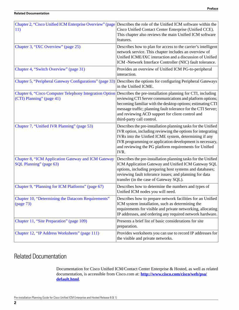
Related Documentation
Documentation for Cisco Unified ICM/Contact Center Enterprise & Hosted, as well as relateddocumentation, is accessible from Cisco.com at: http://www.cisco.com/cisco/web/psa/default.html.
Pre-installation Planning Guide for Cisco Unified ICM Enterprise and Hosted Release 8.0( 1)
2
Preface
Related Documentation
• Related documentation includes the documentation sets for Cisco CTI Object Server (CTIOS), Cisco Agent Desktop (CAD), Cisco Agent Desktop - Browser Edition (CAD-BE), CiscoUnified Contact Center Management Portal, Cisco Unified Customer Voice Portal (CVP),Cisco Unified IP IVR, Cisco Unified Intelligence Center, and Cisco Support Tools.
• For documentation for these Cisco Unified Contact Center Products, go to http://www.cisco.com/cisco/web/psa/default.html, click Voice and Unified Communications,then click Customer Contact, then click Cisco Unified Contact Center Products or CiscoUnified Voice Self-Service Products, then click the product/option you are interested in.
• For troubleshooting tips for these Cisco Unified Contact Center Products, go to http://docwiki.cisco.com/wiki/Category:Troubleshooting, then click the product/option you areinterested in.
• Documentation for Cisco Unified Communications Manager is accessible from: http://www.cisco.com/cisco/web/psa/default.html.
• Technical Support documentation and tools are accessible from: http://www.cisco.com/en/US/support/index.html.
• The Product Alert tool is accessible from (login required): http://www.cisco.com/cgi-bin/Support/FieldNoticeTool/field-notice.
• For information on the Cisco software support methodology, refer to Software Release andSupport Methodology: ICM/IPCC available at (login required): http://www.cisco.com/en/US/partner/products/sw/custcosw/ps1844/prod_bulletins_list.html.
• For a detailed list of language localizations, refer to the Cisco Unified ICM/Contact CenterProduct and System Localization Matrix available at the bottom of the following page: http://www.cisco.com/en/US/products/sw/custcosw/ps1001/prod_technical_reference_list.html.
Product Naming Conventions
In this release, the product names defined in the table below have changed. The New Name(long version) is reserved for the first instance of that product name and in all headings. TheNew Name (short version) is used for subsequent instances of the product name.
Note: This document uses the naming conventions provided in each GUI, which means that insome cases the old product name is in use.
New Name (short version)New Name (long version)Old Product Name
Unified CCECisco Unified Contact CenterEnterprise
Cisco IPCC Enterprise Edition
Unified SCCECisco Unified System Contact CenterEnterprise
Cisco System IPCC Enterprise Edition
Note: Cisco Unified System ContactCenter Enterprise (Unified SCCE) issupported in 8.0(1); however, there is
Pre-installation Planning Guide for Cisco Unified ICM Enterprise and Hosted Release 8.0( 1)
3
Preface
Product Naming Conventions

New Name (short version)New Name (long version)Old Product Name
not a separate 8.0(1) version. If yourequest features that are in 8.0(1), youmust migrate to the UnifiedICM/CCE/CCH software. Fullmigration information is documentedin the Upgrade Guide for Cisco UnifiedICM/Contact Center Enterprise &Hosted.
Unified CCHCisco Unified Contact Center HostedCisco IPCC Hosted Edition
Unified ICMECisco Unified Intelligent ContactManagement Enterprise
Cisco Intelligent Contact Management(ICM) Enterprise Edition
Unified ICMHCisco Unified Intelligent ContactManagement Hosted
Cisco Intelligent Contact Management(ICM) Hosted Edition
Unified CMCisco Unified CommunicationsManager
Cisco CallManager/Cisco UnifiedCallManager
Conventions
This manual uses the following conventions:
DescriptionConvention
Boldface font is used to indicate commands, such as userentries, keys, buttons, and folder and submenu names. Forexample:
boldface font
• Choose Edit > Find.
• Click Finish.
Italic font is used to indicate the following:italic font
• To introduce a new term; for example: A skill group is acollection of agents who share similar skills.
• For emphasis; for example: Do not use the numerical namingconvention.
• A syntax value that the user must replace; for example: IF(condition, true-value, false-value)
• A book title; for example: Refer to the Cisco CRSInstallation Guide.
Window font, such as Courier, is used for the following:window font
Pre-installation Planning Guide for Cisco Unified ICM Enterprise and Hosted Release 8.0( 1)
4
Preface
Conventions
DescriptionConvention
• Text as it appears in code or that the window displays; forexample: <html><title>Cisco Systems,Inc. </title></html>
• Navigational text when selecting menu options; for example:ICM Configuration Manager > Tools> Explorer
Tools > Agent Explorer
Angle brackets are used to indicate the following:< >
• For arguments where the context does not allow italic, suchas ASCII output.
• A character string that the user enters but that does not appearon the window such as a password.
Obtaining Documentation and Submitting a Service Request
For information on obtaining documentation, submitting a service request, and gatheringadditional information, see the monthly What's New in Cisco Product Documentation, whichalso lists all new and revised Cisco technical documentation, at:
http://www.cisco.com/en/US/docs/general/whatsnew/whatsnew.html
Subscribe to the What's New in Cisco Product Documentation as a Really Simple Syndication(RSS) feed and set content to be delivered directly to your desktop using a reader application.The RSS feeds are a free service and Cisco currently supports RSS version 2.0.
Documentation Feedback
You can provide comments about this document by sending email to the following address:
mailto:[email protected]
We appreciate your comments.
Pre-installation Planning Guide for Cisco Unified ICM Enterprise and Hosted Release 8.0( 1)
5
Preface
Obtaining Documentation and Submitting a Service Request

Pre-installation Planning Guide for Cisco Unified ICM Enterprise and Hosted Release 8.0( 1)
6
Preface
Documentation Feedback

Pre-installation Planning OverviewNote: This manual deals with Unified ICME. For information on Unified CCE, see theInstallation and Configuration Guide for Cisco Unified Contact Center Enterprise & Hostedand the Administration Guide for Cisco Unified Contact Center Enterprise & Hosted.
The Unified ICM software is a distributed application that routes telephone calls, web inquiries,and e-mail across geographically distributed contact centers. A typical Unified ICM systemincludes a number of computers located at different sites. A small Unified ICM system mighthave computers at two or three sites. A larger system might have computers at 20 sites or more.
Because the Unified ICM software works with different types of contact center equipment andsometimes one or more carrier networks, some pre-installation planning is necessary to ensurethat the Unified ICM installation process proceeds smoothly and on schedule.
This chapter provides an overview of the Unified ICM pre-installation planning process. It alsocontains a pre-installation planning document roadmap, which suggests an order in which youcan start the tasks.
The Planning Process
The Unified ICM pre-installation planning process involves coordinating and scheduling severaltasks so they are completed in time for the arrival of the Unified ICM server platforms. Youtypically need to make preparations at each site that is to contain Unified ICM components.Some pre-installation tasks may take longer than others. Therefore, try to start the time-consumingtasks early and continue working in parallel on the other pre-installation tasks.
Coordinating and Scheduling Tasks
Cisco suggests that one person in your organization has overall responsibility for coordinatingand scheduling the pre-installation planning tasks. This person can also delegate responsibilityto ensure that tasks are assigned to people with the applicable expertise. For example, you might
Pre-installation Planning Guide for Cisco Unified ICM Enterprise and Hosted Release 8.0( 1)
7
Chapter 1

have your MIS expert begin working with Cisco to order the server platforms. At the same time,your data communications expert can start the process of provisioning network facilities at eachcontact center site.
Pre-installation Document Road Map
The current document provides guidance on topics such as provisioning IXC access, preparingACDs, and determining the Unified ICM datacom requirements. In each case, one or morepre-installation tasks are covered.
You typically start the pre-installation planning tasks in the following order:
1. Getting Started: Document current contact handling procedures. Provide configurationdata for contact center sites. Understand the Unified ICM software. Review Unified ICMproduct options. Determine Unified ICM Configuration.
See Chapter 2, “ICM Enterprise Edition Overview” (page 11); Administration Guide forCisco Unified ICM/Contact Center Enterprise & Hosted.
2. IXC Access: Review ICM/IXC interaction. Choose network link fault tolerances strategy.Review IXC access specifics. See Chapter 3, “IXC Overview” (page 25); the relevantCisco NIC Supplement document.
3. Switch Preparation: Determine ACD requirements. Determine CTI and MIS linkrequirements. Order required upgrades and enhancements. See Chapter 4, “SwitchOverview” (page 31); Chapter 5, “Peripheral Gateway Configurations” (page 33); therelevant Cisco ACD Supplement document(s).
4. Product Options and System Integration: Determine product option requirements. Orderany required upgrades or enhancements. See Chapter 6, “CTI Planning” (page 41); Chapter7, “IVR Planning” (page 53); Chapter 8, “ICM Application Gateway and ICM GatewaySQL Planning” (page 63); .
5. Estimating System Size: Enter data using the Unified ICM database sizing tool. Note thespecifications provided by the tool. Determine the number of PCs required.
See the discussion of the ICM Database Administration tool (ICMDBA) in theAdministration Guide for Cisco Unified ICM/Contact Center Enterprise & Hosted; Chapter9, “Planning for ICM Platforms” (page 67).
6. Network and Site Requirements: Determine requirements for Unified ICM networking.Allocate IP addresses. Order any additional network hardware. Meet basic site requirements.Order additional cabling or other equipment required.
See Chapter 10, “Determining the Datacom Requirements” (page 73); Chapter 11, “SitePreparation” (page 109); Chapter 12, “IP Address Worksheets” (page 111).
For example, since the lead-time for provisioning IXC access is several weeks, this taskis started early in the process. You can then proceed with tasks such as making sure yourcontact center equipment (ACDs, PBXs, IVRs) have the necessary software releases and
Pre-installation Planning Guide for Cisco Unified ICM Enterprise and Hosted Release 8.0( 1)
8
Chapter 1: Pre-installation Planning Overview
The Planning Process

options. While that task is in progress, you can select Unified ICM product options andcomponent platforms and begin preparing the installation sites.
7. Pre-installation EOL Component Check: ICM Installer will check if the below mentionedEOL components are installed in the \ machine before upgrading the machine:
EOL Components
– PG type Md110, Siemens, Rolm9005, Galaxy, G2, ACP1000, Meridian
– MEI Server
– Application Bridge Server
– AIN Network Gateway
Above mentioned components will be removed by the ICM Installer after the user confirmsthat they can be removed.
Caution: Application Bridge Server needs to be manually removed. It is not supported inUnified ICM 8.0. Automatic removal is not provided in this release.
NIC and ACD Supplements
The NIC Supplements are reference documents that contain specific information on how theUnified ICM Network Interface Controller (NIC) interfaces with the supported IXC carriernetworks. The NIC is the software process that allows the Unified ICM system to communicatewith the carrier’s intelligent switching network. You may want to refer to the NIC supplementsfor detailed technical information when you are planning for IXC access.
There are NICs, and NIC Supplements, for each carrier supported by the Unified ICM software(AT&T, MCI, Sprint, and so on). The NIC Supplements are intended to be used as technicalreference companions to the Cisco Unified ICM software documentation set.
The ACD Supplements are reference documents that contain the specific information you needto maintain Unified ICM Peripheral Gateways (PGs) in an Unified ICM environment. The PGis the Unified ICM component that provides an interface to proprietary ACD systems.
There are ACD supplements for each ACD supported by the Unified ICM software (AspectCallCenter, Avaya ACM, Nortel Symposium, and so on). The ACD Supplements are intendedto be used as the ACD-specific companions to the Unified ICM software documentation set.For example, while other Unified ICM documents such as the Configuration Guide for CiscoUnified ICM/Contact Center Enterprise and Hosted and the Scripting and Media Routing Guidefor Cisco Unified ICM/Contact Center Enterprise & Hosted, cover general topics such asconfiguring an overall Unified ICM system and writing scripts to route contact center requests,the ACD Supplements provide specific information on configuring certain types of PGs andmaking any necessary adjustments to the ACD configuration. Refer to the ACD Supplementsfor detailed technical information when you are determining the requirements for your ACDs.
Pre-installation Planning Guide for Cisco Unified ICM Enterprise and Hosted Release 8.0( 1)
9
Chapter 1: Pre-installation Planning Overview
The Planning Process

Pre-installation Planning Guide for Cisco Unified ICM Enterprise and Hosted Release 8.0( 1)
10
Chapter 1: Pre-installation Planning Overview
The Planning Process
Cisco Unified ICME OverviewIn the initial phase of pre-installation planning, you need to become familiar with the UnifiedICM system and understand how it fits into your Unified CCE. You can then determine whichproducts and components you want to deploy in an Unified ICM virtual contact center.
In this chapter, complete the following pre-installation tasks:
• Determine the role of the Unified ICM software in your enterprise. Understand how theUnified ICM software fits into the Unified CCE and carrier networks.
• Choose Unified ICM products. Will your system be a complete pre-routing and post-routingsystem? Will you have other options such as Unified ICM Gateway SQL, Cisco CTI, orUnified IP IVR?
This chapter contains the following topics:
• How the ICM Software Works, page 11• ICM System Components and Processes, page 14• ICM Options and Related Products, page 17
How the ICM Software Works
The Unified ICM Enterprise Edition works with your contact center equipment and the IXCcarrier network to create a virtual contact center. In the virtual contact center model, multipledistributed contact centers are linked to form one Unified CCE. The agents within the UnifiedCCE become members of a single team that is capable of servicing customer contacts throughoutthe enterprise.
Pre-installation Planning Guide for Cisco Unified ICM Enterprise and Hosted Release 8.0( 1)
11
Chapter 2
ICM Call Routing
The Unified ICM software makes the best use of your contact handling resources while ensuringthat each customer is directed to the most appropriate resource available. To get a better ideaof how the Unified ICM software fits into the contact center and carrier environments, it mighthelp to examine how the Unified ICM software routes telephone calls.
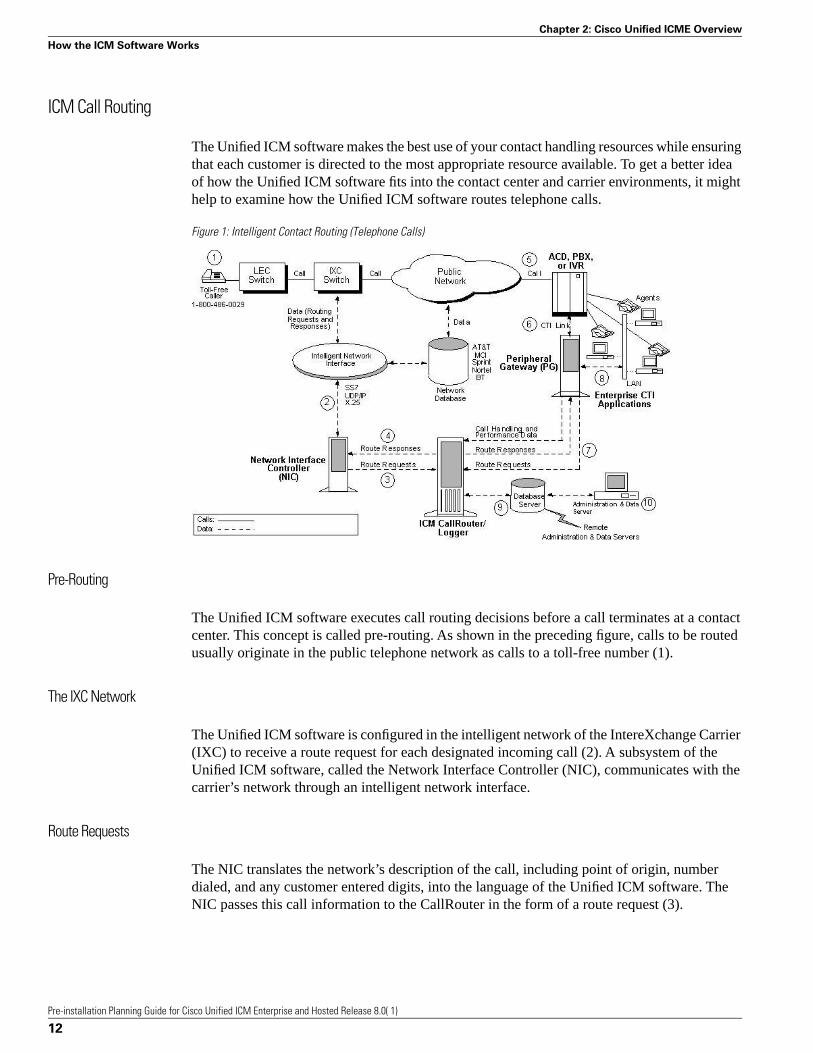
Figure 1: Intelligent Contact Routing (Telephone Calls)
Pre-Routing
The Unified ICM software executes call routing decisions before a call terminates at a contactcenter. This concept is called pre-routing. As shown in the preceding figure, calls to be routedusually originate in the public telephone network as calls to a toll-free number (1).
The IXC Network
The Unified ICM software is configured in the intelligent network of the IntereXchange Carrier(IXC) to receive a route request for each designated incoming call (2). A subsystem of theUnified ICM software, called the Network Interface Controller (NIC), communicates with thecarrier’s network through an intelligent network interface.
Route Requests
The NIC translates the network’s description of the call, including point of origin, numberdialed, and any customer entered digits, into the language of the Unified ICM software. TheNIC passes this call information to the CallRouter in the form of a route request (3).
Pre-installation Planning Guide for Cisco Unified ICM Enterprise and Hosted Release 8.0( 1)
12
Chapter 2: Cisco Unified ICME Overview
How the ICM Software Works

Note: For clarity, the NIC is usually shown in figures as a separate computer. Actually, NICsare implemented as software on the Unified ICM software platform (usually on the CallRouteror CallRouter/Logger [Rogger] machines).
Route Responses
At this point, the Unified ICM software may query an ANI or customer profile database beforereturning a route response to the NIC (4). The NIC passes a destination for the call back to theIXC network. The IXC is responsible for connecting the call and maintaining the voice path.
ACDs
Each contact center has one or more Automatic Call Distributor (ACD) systems that directincoming calls to the telephone sets of individual agents (5). The Unified ICM software maintainsreal-time communications with the ACDs in each contact center by using a Peripheral Gateway(PG).
Peripheral Gateway
The PG communicates with the ACD over the switch vendor’s Computer Telephony Integration(CTI) link (6). To make optimal decisions, the Unified ICM software must know the latest statusfor every call, agent, and agent group in its network. One purpose of the PG is to extract thisstatus information from the ACD and forward it to the CallRouter’s in-memory database. (ThePG can also be used as a CTI Server and as a communications interface between the UnifiedICM and Interactive Voice Response (IVR) systems located at contact center sites or in thenetwork.)
Post-Routing
In private network configurations, ACDs can also originate call routing requests. This is calledpost-routing. Post-routing provides the same intelligence used in pre-Routing, but applies it tocalls originating from a private network of ACD, PBX, and IVR systems. The PG assists inpost-routing by forwarding routing requests to the Unified ICM software and returning the targetdestinations to the ACD (7).
CTI Server
External server or workstation applications can subscribe with a PG that acts as a CTI Server(8). The CTI Server provides call and agent event data that can be used in screen-pops and otherCTI applications. At the desktop level, the Unified ICM CTI desktop provides an environmentfor integrating soft-phone, screen-pop, and data entry at the agent’s workstation.
Monitoring and Reporting
All event data that are gathered by the PG and router are forwarded to the Unified ICM softwareand stored in an industry-standard relational database (9). These data are used in real-timemonitoring and historical reporting. The standard Unified ICM monitoring screens and reports
Pre-installation Planning Guide for Cisco Unified ICM Enterprise and Hosted Release 8.0( 1)
13
Chapter 2: Cisco Unified ICME Overview
How the ICM Software Works

can be easily modified with Unified ICM-provided database access tools. Optionally, the datacan be accessed directly with SQL or Open Database Connectivity (ODBC) tools.
Administration & Data Server
The overall operation of the Unified ICM software is monitored and controlled from anAdministration & Data Server (10) . The Unified ICM software can support multipleAdministration & Data Servers located throughout the contact center network.
ICM System Components and Processes
Many different Unified ICM system software components are involved in pre-installationplanning. You may want to become familiar with the role of the components in the Unified ICMsystem.
Note: Not every component is used in every Unified ICM System.
CallRouter
This is the part of the Unified ICM system that contains the call routing logic. The Unified ICMsoftware receives call routing requests and determines the best destination for each call. It alsocollects information about the entire system. The Unified ICM software serves as a real-timeserver by forwarding performance and monitoring information to Administration & Data servers.
Logger
The Logger is the interface between the Unified ICM software and the database manager (SQLServer). As the Unified ICM software collects performance and monitoring information aboutthe system, it passes the information to the Logger for short-term storage in a central relationaldatabase. The Logger forwards historical information to the Historical Data Server (HDS). TheHDS on the Logger maintains statistics and data for use in monitoring and reporting.
Network Interface Controller (NIC)
The NIC connects the Unified ICM software to the IXC signaling network. The NIC receivesa route request from the signaling network for each incoming call and passes the request to theUnified ICM software. The Unified ICM software responds with routing information (a routinglabel), which the NIC passes back to the IXC signaling network.
Note: For clarity, the NIC is usually shown in figures as a separate computer. Actually, NICsare implemented as software on the Unified ICM software platform (usually on the CallRouteror CallRouter/Logger [Rogger] machines).
Pre-installation Planning Guide for Cisco Unified ICM Enterprise and Hosted Release 8.0( 1)
14
Chapter 2: Cisco Unified ICME Overview
ICM System Components and Processes

Peripheral Gateways
Each contact center device (ACD, PBX, or IVR) communicates with a Peripheral Gateway(PG). The PG reads status information from the device and passes it back to the Unified ICMsoftware. The PG runs one or more Peripheral Interface Manager (PIM) processes, which arethe software components that communicate with proprietary ACD systems. A single PIM isrequired for each peripheral to which the PG will interface. Therefore, a single PG (and itsassociated PIMs) can serve multiple peripherals of the same kind. For example, one PG withfour Aspect ACD PIMs can serve four Aspect ACDs in the contact center.
Note: A single PG can support both ACD PIMs and IVR PIMs; however, the ACD PIMs andthe IVR PIMs must all be the same type of PIM (ACD PIMs must be the same type; IVR PIMsmust be the same type).
A single server can support up to two PGs. For details, refer to the Configuration Guide forCisco Unified ICM/Contact Center Enterprise and Hosted.
Administration & Data Server
The Administration & Data Server is the human interface to the Unified ICM software. It servesas a control console from which you can monitor agent and contact center activity and changehow the Unified ICM software routes calls. For example, you can use the Administration &Data Server to configure the Unified ICM contact center data, create call routing scripts, andmonitor and report on the Unified ICM system or some part of the system. Administration &Data Servers can be located anywhere, as long as they have LAN or WAN connections to theUnified ICM software.
Administration & Data Servers have several roles: Administration, Real-time data server,Historical Data Server, and Detail Data Server. A Unified ICM deployment must haveAdministration & Data Servers to fill these roles. The servers may be deployed in the followingcombinations to achieve the needed scalability with the minimum number of servers:
• Administration Server and Real-time Data Server (AW)
• Configuration only Administration Server
• Administration Server, Real-time and Historical Data Server and Detail Data Server(AW-HDS-DDS)
• Administration Server and Real-time and Historical Data Server (AW-HDS)
• Historical Data Server and Detail Data Server (HDS-DDS)
An Administration Client (formerly known as a “client AW”) serves the administration role,but is deployed as a client to an Administration Server for scalability. The Administration Clientmay view and modify the configuration, and receive real-time reporting data from theAdministration & Data Server, but does not store the data itself, and does not have a database.Each Administration & Data Server must be installed on a separate server for production systems
Pre-installation Planning Guide for Cisco Unified ICM Enterprise and Hosted Release 8.0( 1)
15
Chapter 2: Cisco Unified ICME Overview
ICM System Components and Processes

to ensure no interruptions to the real-time call processing of the Call Router and Logger processes.For lab or prototype systems, the Administration & Data Server (with the WebView Serveroption) can be installed on the same server as the Call Router and Logger.
Historical Data Server
Administration & Data Servers need to access historical data (half hour data, call detail, and soon) for historical reporting in the Script Editor or in third-party tools. At least one real-timeAdministration & Data Servers, in a system, must be installed with a Historical Data Server(HDS) to support reporting and long-term historical data storage. The HDS IP addressrequirements are identical to those of a standard Administration & Data Server.
ICM Reporting
The Unified ICM Reporting solution provides an interface to access data describing the historicaland real-time states of the system.
The reporting solution consists of the following components:
• Unified IC or WebView —reporting user interfaces
• Configuration and Reporting Data — contained on Administration & Data Server(s)
Reporting concepts and data descriptions are described in Reporting Guide for Cisco UnifiedICM/Contact Center Enterprise & Hosted; this description is independent of the reporting userinterface being used.
Cisco Unified Intelligence Center
Cisco Unified Intelligence Center (Unified IC) is an advanced reporting product used for CCEand other products. This platform is a web-based application offering many Web 2.0 features,high scalability, performance, and advanced features such as the ability to integrate data fromother Cisco Unified Communications products or third-party data sources. Unified IC incorporatesa security model which defines different access and capabilities for specific users. Unified ICStandard is included with Unified ICM. Unified IC Premium is an optional product withadditional features. Unified IC must be installed on a separate server; it cannot be co-residentwith other Unified ICM components.
For a complete description of both Unified IC products see Reporting Guide for Cisco UnifiedICM/Contact Center Enterprise & Hosted.
WebView
WebView is a web-based application for Unified ICM reporting. WebView performs the basicoperations of gathering user input, querying the databases and presenting the requested data forboth real time and historic data.
Pre-installation Planning Guide for Cisco Unified ICM Enterprise and Hosted Release 8.0( 1)
16
Chapter 2: Cisco Unified ICME Overview
ICM System Components and Processes

Note: WebView does not support historical data which is collected in 15 minute intervals (afeature new in Release 8.0(1)). WebView only supports historical reporting for data collectedin half hour intervals. WebView also does not supply reports for the call type/skill group data(new in Release 8.0(1)). Unified IC must be used for 15 minute data intervals or call type/skillgroup reporting.
WebView has the ability to export data, launch scheduled reports, save and share report settings,and mark favorite reports. It also has features to display service affecting events reported bythe system. WebView can be installed on an Administration & Data Server. To increasescalability, Webview can be installed on a standalone server.
The WebView architecture is described in the WebView Installation and Administration Guide,available at http://www.cisco.com/en/US/products/sw/custcosw/ps4145/prod_installation_guides_list.html . For a description of all of the reports provided withWebView, refer to the WebView Template Reference Guide for Cisco Unified Contact CenterEnterprise & Hosted, available at http://www.cisco.com/en/US/products/sw/custcosw/ps4145/products_user_guide_list.html.
ICM Options and Related Products
The Unified ICM software can be set up with a variety of options, such as adding software toperform database lookups or performing secondary call routing once a call has terminated at anACD. In some cases, the Unified ICM software is an integral part of other Cisco contact centerproducts, such as the IP Contact Center (IPCC). You may want to review the Unified ICMsoftware options and related products to learn about the different ways the Unified ICM softwarecan be deployed in a Unified CCE.
Pre-Routing
Pre-Routing allows the Unified ICM software to execute routing decisions before a call terminatesat a contact center. With pre-routing, the Network Interface Controller (NIC) receives the routerequest from the IXC and passes the call information to the Unified ICM software. The UnifiedICM software processes the route request through a call routing script, which defines how thecall should be routed. The Unified ICM software returns a route response to the NIC, which inturn forwards it to the IXC. The route response contains the call’s final destination.
In pre-routing, the Peripheral Gateway’s role is to keep the Unified ICM software informed ofthe real-time status of switches, calls, and agents in the Unified CCE. The Unified ICM softwareuses this real-time data to make an informed call routing decision.
Pre-Routing systems require the following components:
• Network Interface Controller (NIC)
• CallRouter
• Logger
• Administration & Data Server
Pre-installation Planning Guide for Cisco Unified ICM Enterprise and Hosted Release 8.0( 1)
17
Chapter 2: Cisco Unified ICME Overview
ICM Options and Related Products

• WebView Server
• Peripheral Gateway (PG)
The pre-routing capabilities are enabled through the Network Interface Controller (NIC) andthe CallRouter processes. NICs are implemented as software on the Unified ICM softwareplatform (for example, on the CallRouter or Logger machines).
The Unified ICM routes calls within the public network based on several dynamic variables.You can use any combination of the following variables to route calls:
Day of weekAgent availability
Number dialedAgent skills
Origin of callCaller-entered digits
Cost of the transactionCost of the call
Scheduled agentsCustomer database lookup
Time of dayCustomer-defined business rules
Calls are routed in the most efficient manner possible given the current contact center loadconditions.
Post-Routing
In a traditional time-division multiplexing (TDM) environment, post-routing systems havesoftware that allows the CallRouter to make secondary routing decisions after a call has beenreceived at a contact center. In post-routing, the ACD or IVR submits a route request to theUnified ICM software. The Unified ICM software executes scripts to process the routing requestand return a destination address to the ACD. The Unified ICM software then directs the ACDto transfer the call to an agent, skill group, or service, either in the same contact center or at adifferent contact center. In making a post-routing decision, the Unified ICM software can usethe same information and script it uses in pre-routing. In other words, the same call routingintelligence that is used in the pre-routing of calls is applied to calls that are interflowed betweencontact center sites, transferred between agents, or transferred into or out of IVRs.
Pre- and Post-Routing Systems
A pre- and post-routing Unified ICM system is a complete intelligent call routing, monitoring,and reporting system. The Unified ICM software can execute routing decisions before a callterminates at a contact center. It can also make secondary routing decisions after a call has beenreceived at a contact center. A Pre- and post-routing system can be expanded with optionalfeatures such as Unified ICM Application Gateway, Unified ICM Gateway SQL, Unified ICMIVR interface, and CTI Server to create an intelligent call routing and management solution inwhich all the elements of the Unified CCE play a role in intelligent routing.
Pre-installation Planning Guide for Cisco Unified ICM Enterprise and Hosted Release 8.0( 1)
18
Chapter 2: Cisco Unified ICME Overview
ICM Options and Related Products

Computer Telephony Integration (CTI)
Cisco CTI software provides an interface between the Unified ICM software and agent desktopand server applications. The CTI software works with a PG’s ACD and IVR interface softwareand all associated ACDs to track events and transactions and forward call- and transaction-relateddata to an agent’s desktop computer.
The CTI software has full third-party call control features that allow agents and integrateddesktop applications to perform tasks such as transferring calls, conferencing calls, and settingcall data all within an enterprise framework. Voice and data collected by an agent at the desktopcan be transferred in the form of a screen-pop among agents and across different ACD platforms.This allows customer and transaction data to accompany a call from an IVR or web server tothe agent and from site-to-site as required. The Unified ICM system can also use CTI data todetermine call destinations based on factors such as customer value, business objectives, marketpenetration, and personalized service.
CTI Server
CTI Server, the basic server component of Cisco CTI, enables the Unified ICM software todeliver agent, call, and customer data in real-time to a server and/ or workstation application asevents occur throughout the life of a call. The CTI Server is a software process that runs on aPeripheral Gateway (PG).
It is a gateway into the Unified ICM software’s data and services.
• Pre-route indications identify a caller and provide associated attributes to applications whilethe call is still in the public or private network and before the caller is connected to an agent,web server or IVR.
• Call events are provided throughout all stages of the call flow, from the moment a call arrivesat an answering location (ACD, PBX, IVR, web server) until the caller hangs up.
• Agent work state changes are reported as they occur.
Cisco CTI Object Server (CTIOS)
CTI Object Server (CTIOS) is a high-performance, scalable, fault-tolerant server-based solutionfor deploying CTI applications. It serves as a single point of integration for third-partyapplications, including Customer Relationship Management (CRM) systems, data mining, andworkflow solutions.
CTIOS is a client of CTI Server, and has a single all-events connection to Cisco CTI Server. Inturn, CTIOS accepts client connections using session, agent, and call interfaces. These interfacesare implemented in .NET, COM, Java, and C++, allowing for a wide range of applicationdevelopment uses. The interfaces are used for call control, to access data values, and to receiveevent notifications.
Pre-installation Planning Guide for Cisco Unified ICM Enterprise and Hosted Release 8.0( 1)
19
Chapter 2: Cisco Unified ICME Overview
ICM Options and Related Products
CTIOS configuration and behavior information is managed at the CTIOS server, simplifyingcustomization, updates, and maintenance. Servers can be accessed and managed remotely.Thin-client and browser-based applications that do not require Cisco software on the desktopcan be developed and deployed with CTIOS.
CTIOS incorporates the following major components:
• CTIOS Toolkit
• Client Interface Library
• CTIOS Combo Desktop for Agents and Supervisors
Note: Refer to the Cisco CTIOS Software documentation for more information.
IVR Interface
This option allows for running a Voice Response (IVR) system. The IVR interface softwareruns on a PG platform. It allows the Cisco Unified ICM software to route calls to targets onIVRs and collect data from IVRs for use in call routing, real-time monitoring, and historicalreporting.
The IVR interface can also provide queuing at a network-based or premises-based IVR. Withthis feature, calls can be directed to an IVR queue when no other appropriate answering resourceis available. The IVR interface is not specific to a particular IVR system or manufacturer. It isbased on an open IVR model. Many IVR systems support Cisco’s Open IVR InterfaceSpecification, including Unified CVP.
The Cisco Customer Voice Portal integrates with both traditional time-division multiplexing(TDM) and IP-based contact centers to provide a call-management and call-treatment solutionwith a self-service IVR option that can use information available to customers on the corporateWeb server. With support for automated speech recognition (ASR) and text-to-speech (TTS)capabilities, callers can obtain personalized information and can conduct business withoutinteracting with a live agent.
Note: Unified CVP was previously called Internet Service Node (ISN).
For a list of IVRs that support this interface, contact your Cisco representative.
Note: You can integrate IVR systems into the Cisco Unified ICM software in several differentways. Chapter 7, “IVR Planning” (page 53) provides more information on IVR integrationalong with examples of how you might integrate IVRs with the Cisco Unified ICM system.
ICM Application Gateway
The Cisco Unified ICM Application Gateway option allows the Cisco Unified ICM softwareto interact with a host system that is running another contact center application. Within the CiscoUnified ICM software, the Gateway feature is implemented as an Application Gateway nodein a call routing script. You add an Application Gateway node to a script to instruct the system
Pre-installation Planning Guide for Cisco Unified ICM Enterprise and Hosted Release 8.0( 1)
20
Chapter 2: Cisco Unified ICME Overview
ICM Options and Related Products

to execute an external application. This allows the script to evaluate responses from the externalapplication and base subsequent routing decisions on the results produced by the application.
The Gateway option allows the Cisco Unified ICM system to interface with any externalapplication, not just database applications.
You can use the Gateway option within the Cisco Unified ICM system to:
• Allow other applications to select a call’s destination.
• Control or trigger external applications through Cisco Unified ICM call routing scripts.
• Pass data to and collect data from other contact center applications.
For example, a simple Gateway application might return a variable to the CallRouter thatidentifies the caller as having a premium account. The routing script can use this informationto control where and how the call is routed. Optionally, the Cisco Unified ICM can pass theretrieved information to the site that is receiving the call. Data such as account numbers, dates,billing phone numbers, and addresses can be passed along with the call to an answering resource.
Note: Chapter 8, “ICM Application Gateway and ICM Gateway SQL Planning (page 63)”provides more information on planning for the Gateway feature.
ICM Gateway SQL
Cisco Unified ICM Gateway SQL allows the Cisco Unified ICM software to query an externalSQL Server database and use the data in call routing. If you have databases that contain customeraccount or profile information, you might want to perform database lookups to assist in callrouting. The database lookups can be based on Calling Line ID (CLID), Dialed Number (DN),or Caller Entered Digits (CED) such as account or social security numbers.
A typical Gateway SQL application might prioritize callers. For example, a call routing scriptmight use the caller’s CLID to access a database and retrieve data about the caller such as thecaller’s average monthly bill. Based on this information, the routing script would route the callerto the most appropriate answering resource.
The following figure shows a basic Gateway SQL configuration. Note that this configurationrequires an additional database server on which you can load the external SQL Server databaseand data.
Pre-installation Planning Guide for Cisco Unified ICM Enterprise and Hosted Release 8.0( 1)
21
Chapter 2: Cisco Unified ICME Overview
ICM Options and Related Products
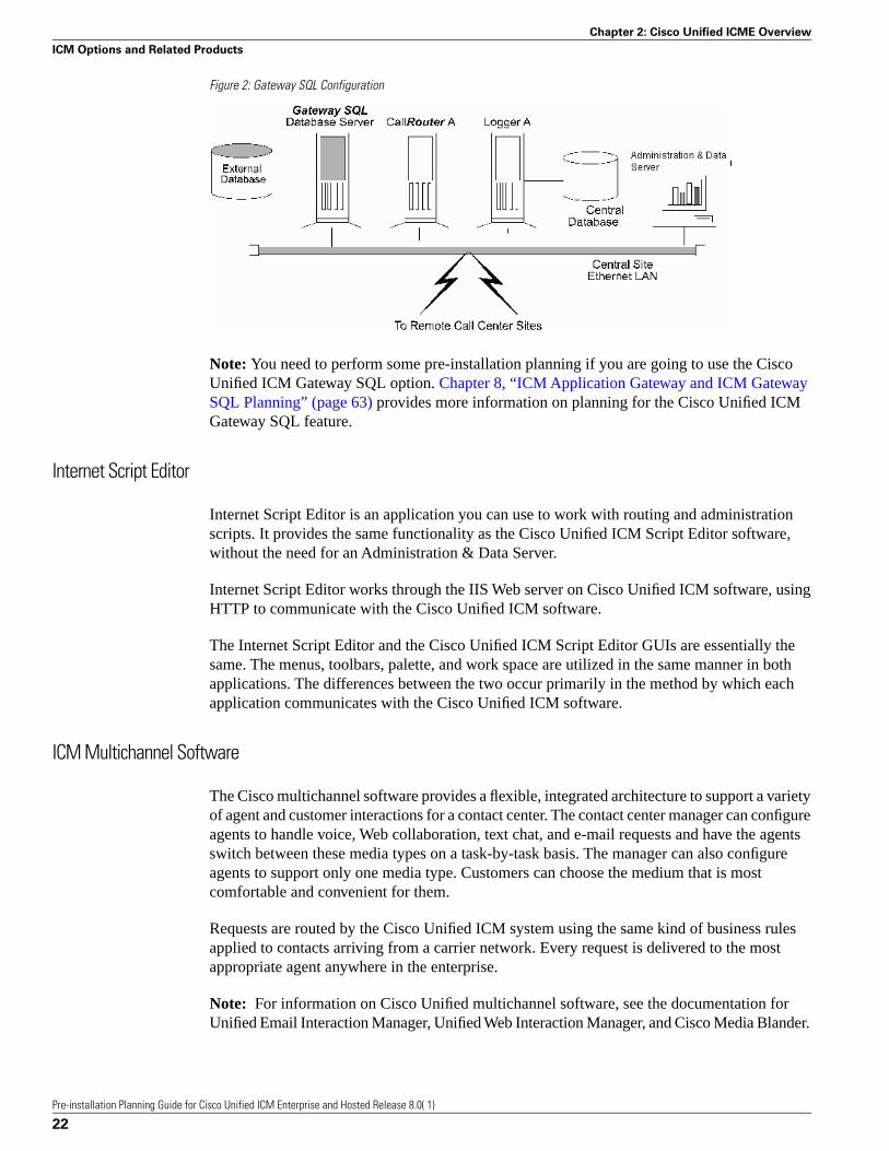
Figure 2: Gateway SQL Configuration
Note: You need to perform some pre-installation planning if you are going to use the CiscoUnified ICM Gateway SQL option. Chapter 8, “ICM Application Gateway and ICM GatewaySQL Planning” (page 63) provides more information on planning for the Cisco Unified ICMGateway SQL feature.
Internet Script Editor
Internet Script Editor is an application you can use to work with routing and administrationscripts. It provides the same functionality as the Cisco Unified ICM Script Editor software,without the need for an Administration & Data Server.
Internet Script Editor works through the IIS Web server on Cisco Unified ICM software, usingHTTP to communicate with the Cisco Unified ICM software.
The Internet Script Editor and the Cisco Unified ICM Script Editor GUIs are essentially thesame. The menus, toolbars, palette, and work space are utilized in the same manner in bothapplications. The differences between the two occur primarily in the method by which eachapplication communicates with the Cisco Unified ICM software.
ICM Multichannel Software
The Cisco multichannel software provides a flexible, integrated architecture to support a varietyof agent and customer interactions for a contact center. The contact center manager can configureagents to handle voice, Web collaboration, text chat, and e-mail requests and have the agentsswitch between these media types on a task-by-task basis. The manager can also configureagents to support only one media type. Customers can choose the medium that is mostcomfortable and convenient for them.
Requests are routed by the Cisco Unified ICM system using the same kind of business rulesapplied to contacts arriving from a carrier network. Every request is delivered to the mostappropriate agent anywhere in the enterprise.
Note: For information on Cisco Unified multichannel software, see the documentation forUnified Email Interaction Manager, Unified Web Interaction Manager, and Cisco Media Blander.
Pre-installation Planning Guide for Cisco Unified ICM Enterprise and Hosted Release 8.0( 1)
22
Chapter 2: Cisco Unified ICME Overview
ICM Options and Related Products

Cisco Unified Contact Center
Cisco Unified Contact Center combines Cisco’s IP telephony products and Cisco Unified ICMsoftware to create an IP-based contact management solution. Cisco Unified Contact Centerprovides a migration path to an IP-based contact center by supporting integration with legacycall center platforms and networks. With Cisco Unified Contact Center, agents can use CiscoIP phones to receive both time-TDM and VoIP phone calls. Capabilities of the Cisco UnifiedContact Center include intelligent call routing, ACD functionality, network-to-desktop CTI,Unified IP IVR integration, call queuing, and consolidated reporting.
Cisco Unified Contact Center is based mainly on two Cisco products: Unified CM and ICMsoftware. Unified CM provides traditional PBX telephony features in an IP telephonyenvironment. Unified ICM software provides enterprise-wide management and distribution ofvoice and data from ACDs, Unified IP IVR systems, small office/home office (SOHO) agents,and desktop applications. Cisco Unified IP phones and Unified IP IVRs (as well as traditionalTDM IVRs) are also part of the Cisco Unified Contact Center.
Note: For information on Unified CCE, see the Installation Guide for Cisco Unified ICM/ContactCenter Enterprise & Hosted and the Administration Guide for Cisco Unified ICM/ContactCenter Enterprise & Hosted.
Pre-installation Planning Guide for Cisco Unified ICM Enterprise and Hosted Release 8.0( 1)
23
Chapter 2: Cisco Unified ICME Overview
ICM Options and Related Products

Pre-installation Planning Guide for Cisco Unified ICM Enterprise and Hosted Release 8.0( 1)
24
Chapter 2: Cisco Unified ICME Overview
ICM Options and Related Products

IXC OverviewIf pre-routing is to be performed, the Unified ICM Enterprise Edition software requires accessto the IntereXchange Carrier intelligent call routing network. Each interexchange carrier offersintelligent network services that allow customer-premises equipment to participate innetwork-level call routing. The Unified ICM software connects to one or more networks byusing a Cisco Network Interface Controller (NIC).
Specifically, this chapter helps you to complete the following tasks:
• Choose your carrier(s). Cisco supports network interfaces with several carriers. You can useone or more carriers with the Unified ICM software.
• Choose the types of network link fault tolerance to apply. It is important to apply faulttolerance in the network interface and the links to the carrier’s intelligent network.
• Order intelligent network service. Once you review the requirements for your specific CiscoNIC, order intelligent network service and work with the carrier and Cisco to bring the serviceon line.
This chapter contains the following topics:
• ICM Software and IXC Interaction, page 25• Applying Fault Tolerance in NICs, page 28
ICM Software and IXC Interaction
The Network Interface Controller (NIC) is the interface between the Unified ICM software andthe IXC intelligent network. The NIC communicates with the IXC network by using networkcontrol links. These links are typically offered as part of the carrier’s intelligent network service.
Cisco provides a NIC to interface to the specific carrier network. For example, if you haveSprint toll-free service, your Unified ICM system is equipped with a Cisco-supplied Sprint NIC.
Pre-installation Planning Guide for Cisco Unified ICM Enterprise and Hosted Release 8.0( 1)
25
Chapter 3

The Sprint NIC allows the Unified ICM to interface with the Sprint intelligent network service.If you use both AT&T and Sprint as carriers, your Unified ICM system is equipped with AT&Tand Sprint NICs. The following figure shows the interaction between the IXC network and theUnified ICM NIC.
Figure 3: Network Interface Controller
For clarity, the NIC in the figure above is shown as a separate computer. Actually, NICs areimplemented as software on the Unified ICM software platform (for example, on the CallRouteror Logger machines).
An Unified ICM Network Gateway can be implemented for SS7 networks. The Unified ICMNetwork Gateway is implemented as a separate node on the Unified ICM signaling accessnetwork. When this node is implemented, the NIC software can be installed on the CallRoutermachine. For Sigtran SS7 networks, a Sigtran Gateway can be deployed on either the CallRoutermachine or a separate machine; the NIC software is installed on the CallRouter machine.
The specific flow of messages to and from the NIC within the Unified ICM software and theIXC network is shown by the circled numbers in the above diagram, and is explained in thefollowing sections below.
Toll-Free Caller
As shown in the preceding figure, the flow of messages between the network and the UnifiedICM begins when a caller dials a toll-free number (1).
LEC-to-IXC
The Local Exchange Carrier (LEC) determines which interexchange carrier (IXC) is providingtransport for that particular number and forwards the call to the IXC switch (2).
Pre-installation Planning Guide for Cisco Unified ICM Enterprise and Hosted Release 8.0( 1)
26
Chapter 3: IXC Overview
ICM Software and IXC Interaction
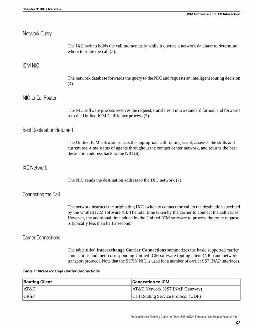
Network Query
The IXC switch holds the call momentarily while it queries a network database to determinewhere to route the call (3).
ICM NIC
The network database forwards the query to the NIC and requests an intelligent routing decision(4).
NIC-to-CallRouter
The NIC software process receives the request, translates it into a standard format, and forwardsit to the Unified ICM CallRouter process (5)
Best Destination Returned
The Unified ICM software selects the appropriate call routing script, assesses the skills andcurrent real-time status of agents throughout the contact center network, and returns the bestdestination address back to the NIC (6).
IXC Network
The NIC sends the destination address to the IXC network (7).
Connecting the Call
The network instructs the originating IXC switch to connect the call to the destination specifiedby the Unified ICM software (8). The total time taken by the carrier to connect the call varies.However, the additional time added by the Unified ICM software to process the route requestis typically less than half a second.
Carrier Connections
The table titled Interexchange Carrier Connections summarizes the basic supported carrierconnections and their corresponding Unified ICM software routing client (NIC) and networktransport protocol. Note that the SS7IN NIC is used for a number of carrier SS7 INAP interfaces.
Table 1: Interexchange Carrier Connections
Connection to ICMRouting Client
AT&T Network (SS7 INAP Gateway)AT&T
Call Routing Service Protocol (UDP)CRSP
Pre-installation Planning Guide for Cisco Unified ICM Enterprise and Hosted Release 8.0( 1)
27
Chapter 3: IXC Overview
ICM Software and IXC Interaction
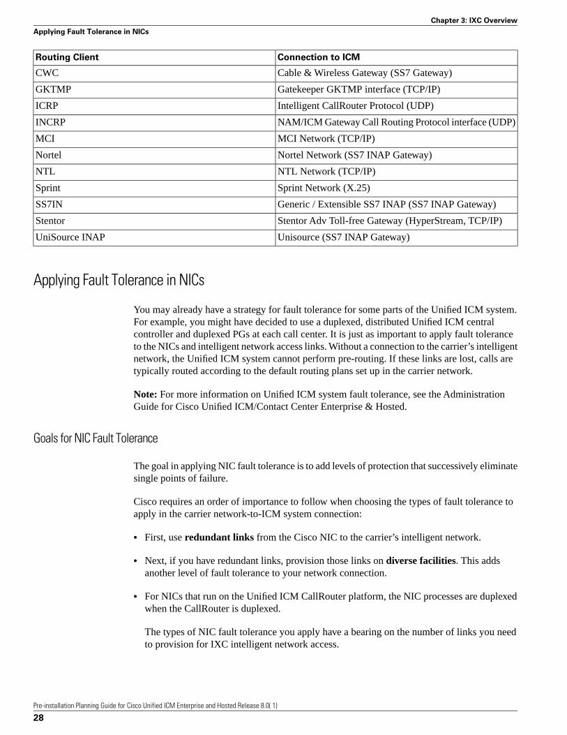
Connection to ICMRouting Client
Cable & Wireless Gateway (SS7 Gateway)CWC
Gatekeeper GKTMP interface (TCP/IP)GKTMP
Intelligent CallRouter Protocol (UDP)ICRP
NAM/ICM Gateway Call Routing Protocol interface (UDP)INCRP
MCI Network (TCP/IP)MCI
Nortel Network (SS7 INAP Gateway)Nortel
NTL Network (TCP/IP)NTL
Sprint Network (X.25)Sprint
Generic / Extensible SS7 INAP (SS7 INAP Gateway)SS7IN
Stentor Adv Toll-free Gateway (HyperStream, TCP/IP)Stentor
Unisource (SS7 INAP Gateway)UniSource INAP
Applying Fault Tolerance in NICs
You may already have a strategy for fault tolerance for some parts of the Unified ICM system.For example, you might have decided to use a duplexed, distributed Unified ICM centralcontroller and duplexed PGs at each call center. It is just as important to apply fault toleranceto the NICs and intelligent network access links. Without a connection to the carrier’s intelligentnetwork, the Unified ICM system cannot perform pre-routing. If these links are lost, calls aretypically routed according to the default routing plans set up in the carrier network.
Note: For more information on Unified ICM system fault tolerance, see the AdministrationGuide for Cisco Unified ICM/Contact Center Enterprise & Hosted.
Goals for NIC Fault Tolerance
The goal in applying NIC fault tolerance is to add levels of protection that successively eliminatesingle points of failure.
Cisco requires an order of importance to follow when choosing the types of fault tolerance toapply in the carrier network-to-ICM system connection:
• First, use redundant links from the Cisco NIC to the carrier’s intelligent network.
• Next, if you have redundant links, provision those links on diverse facilities. This addsanother level of fault tolerance to your network connection.
• For NICs that run on the Unified ICM CallRouter platform, the NIC processes are duplexedwhen the CallRouter is duplexed.
The types of NIC fault tolerance you apply have a bearing on the number of links you needto provision for IXC intelligent network access.
Pre-installation Planning Guide for Cisco Unified ICM Enterprise and Hosted Release 8.0( 1)
28
Chapter 3: IXC Overview
Applying Fault Tolerance in NICs

Link Redundancy
Cisco requires that you configure redundant links to the IXC network. In other words, ratherthan having a single link from the NIC to the IXC intelligent network, provision two links.Having just one link to the IXC network represents a single point of failure (that is, an area ornode in the system that, should it fail, could cause the system to stop routing calls).
By using redundant links, you increase the reliability of the IXC network connection and addan important level of fault tolerance to the system. The following figure shows a simplexedUnified ICM central controller and NIC with redundant links to the IXC network.
Figure 4: Redundant Links
In the preceding figure, single points of failure still exist because the NIC, CallRouter, andLogger are simplexed. The simplexed central controller and NIC configuration is shown hereonly as an example. This type of simplexed configuration is used only for non-critical systemsthat can tolerate potentially long interruptions in service (for example, in lab or demo systems).
The major IXCs support redundant links to their intelligent networks. Contact your carrier formore information on access link options.
Route Diversity
For even more protection against network outages, Cisco requires that the network links beprovisioned on diverse network facilities. By having diverse links, you further reduce the riskthat another single point of failure (in this case, the failure of a circuit) might cause you to losethe connection to the IXC network. For example, you might provision one access link on oneT1 circuit and provision the other access link on a different T1 circuit. By having diverse links,you protect against network failures in which an entire circuit is lost.
Pre-installation Planning Guide for Cisco Unified ICM Enterprise and Hosted Release 8.0( 1)
29
Chapter 3: IXC Overview
Applying Fault Tolerance in NICs
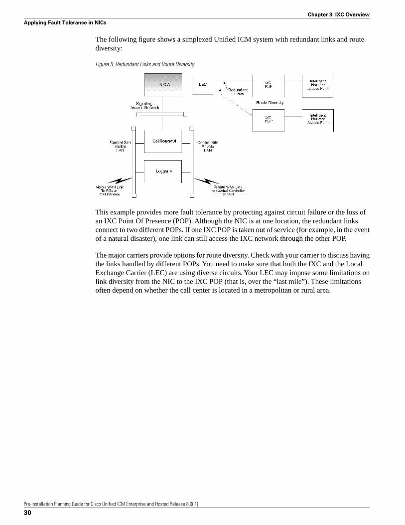
The following figure shows a simplexed Unified ICM system with redundant links and routediversity:
Figure 5: Redundant Links and Route Diversity
This example provides more fault tolerance by protecting against circuit failure or the loss ofan IXC Point Of Presence (POP). Although the NIC is at one location, the redundant linksconnect to two different POPs. If one IXC POP is taken out of service (for example, in the eventof a natural disaster), one link can still access the IXC network through the other POP.
The major carriers provide options for route diversity. Check with your carrier to discuss havingthe links handled by different POPs. You need to make sure that both the IXC and the LocalExchange Carrier (LEC) are using diverse circuits. Your LEC may impose some limitations onlink diversity from the NIC to the IXC POP (that is, over the “last mile”). These limitationsoften depend on whether the call center is located in a metropolitan or rural area.
Pre-installation Planning Guide for Cisco Unified ICM Enterprise and Hosted Release 8.0( 1)
30
Chapter 3: IXC Overview
Applying Fault Tolerance in NICs

Switch OverviewEach contact center device (ACD, PBX, or IVR) communicates with an Unified ICM PeripheralGateway (PG). The PG reads status information from the device and passes it back to the UnifiedICM software. The PG runs one or more Peripheral Interface Manager (PIM) processes, whichare the software components that communicate with proprietary ACD systems. One PIM isrequired for each peripheral to which the PG will interface. So if you have two identical ACDs,your PG will require two PIMs.
A single PG can serve multiple peripherals of the same kind. For example, one computer withan Aspect PG and several Aspect PIMs can serve several Aspect ACDs in the contact center.Another PG and PIM on the same computer might serve an IVR.
Note: A single PG can support both ACD PIMs and IVR PIMs, though the ACD PIMs mustall be of the same kind.
This chapter provides an overview of how the PG interfaces with ACDs in a contact centerenvironment.
This chapter contains the following topics:
• PG-to-Peripheral Connections, page 31• Supported ACD Switches, page 32
PG-to-Peripheral Connections
Each contact center peripheral (ACD, PBX, or IVR) requires a connection to a Cisco PeripheralGateway (PG). The Peripheral Gateway provides a software interface between ACD, PBX, andIVR systems and the Unified ICM routing software.
The PG connects to a peripheral via the peripheral’s computer telephony integration (CTI) link.In some cases, the PG also connects to the peripheral’s MIS subsystem. The MIS subsystem
Pre-installation Planning Guide for Cisco Unified ICM Enterprise and Hosted Release 8.0( 1)
31
Chapter 4
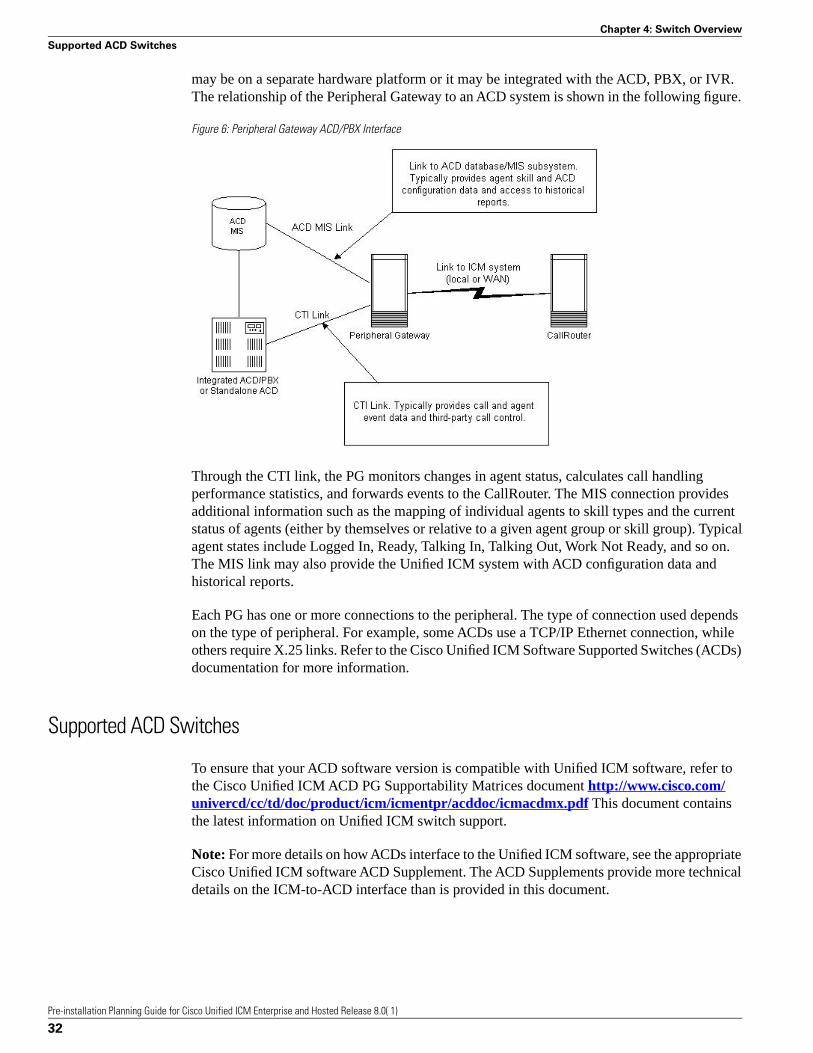
may be on a separate hardware platform or it may be integrated with the ACD, PBX, or IVR.The relationship of the Peripheral Gateway to an ACD system is shown in the following figure.
Figure 6: Peripheral Gateway ACD/PBX Interface
Through the CTI link, the PG monitors changes in agent status, calculates call handlingperformance statistics, and forwards events to the CallRouter. The MIS connection providesadditional information such as the mapping of individual agents to skill types and the currentstatus of agents (either by themselves or relative to a given agent group or skill group). Typicalagent states include Logged In, Ready, Talking In, Talking Out, Work Not Ready, and so on.The MIS link may also provide the Unified ICM system with ACD configuration data andhistorical reports.
Each PG has one or more connections to the peripheral. The type of connection used dependson the type of peripheral. For example, some ACDs use a TCP/IP Ethernet connection, whileothers require X.25 links. Refer to the Cisco Unified ICM Software Supported Switches (ACDs)documentation for more information.
Supported ACD Switches
To ensure that your ACD software version is compatible with Unified ICM software, refer tothe Cisco Unified ICM ACD PG Supportability Matrices document http://www.cisco.com/univercd/cc/td/doc/product/icm/icmentpr/acddoc/icmacdmx.pdf This document containsthe latest information on Unified ICM switch support.
Note: For more details on how ACDs interface to the Unified ICM software, see the appropriateCisco Unified ICM software ACD Supplement. The ACD Supplements provide more technicaldetails on the ICM-to-ACD interface than is provided in this document.
Pre-installation Planning Guide for Cisco Unified ICM Enterprise and Hosted Release 8.0( 1)
32
Chapter 4: Switch Overview
Supported ACD Switches

Peripheral Gateway ConfigurationsAs part of planning for ACDs and PGs, you need to decide whether your Peripheral Gatewayswill be simplexed or duplexed. Simplexed means that one PG is used. Duplexed means that twoessentially identical PGs are used, one as a backup system. (Both PGs run simultaneously, withsome processes active on both PGs. See the discussion in Peripheral Gateway Fault Tolerance(page 34).)
The following figure shows examples of simplexed and duplexed contact center configurations.Typically, duplexed PGs are installed for fault tolerance.
Figure 7: PG Contact Center Configurations
Note: Some ACDs can connect directly to the Unified ICM visible LAN. Others connect to thePG via serial or other types of communication links.
Pre-installation Planning Guide for Cisco Unified ICM Enterprise and Hosted Release 8.0( 1)
33
Chapter 5

The Peripheral Gateway reads information from one or more peripherals at a contact center andsends status information back to the Unified ICM CallRouter. A peripheral might be an ACD,IVR, PBX, or another device that distributes calls within the contact center. If the Unified ICMsystem is performing post-routing, the PG also sends route requests to the CallRouter andreceives routing instructions in response.
This chapter contains the following topics:
• Peripheral Gateway Fault Tolerance, page 34• PG Platform Options, page 36• Standard PG Configuration, page 38• Remote ACD and IVR Connection to PGs, page 38• Multiple PGs Connecting to a Single ACD, page 39
Peripheral Gateway Fault Tolerance
Duplexed PGs are usually implemented to provide fault tolerance in the Unified ICM software’scommunication with peripherals. The duplexed PGs use a private network. The PG privatenetwork is used to synchronize certain processes within a duplexed PG pair. It is also used in“heartbeat detection,” which is a process by which each PG sends a heartbeat packet every100ms to keep track of the “health” of the other PG.
PGs use a combination of the hot standby and synchronization approaches to fault tolerance.In the hot standby approach, one set of processes is called the primary, and the other is calledthe backup. In this model, the primary process performs the work at hand while the backupprocess is idle. In the event of a primary process failure, the backup process is activated andtakes over. In a duplexed PG system, the Peripheral Interface Manager (PIM) processes use thehot standby approach to fault tolerance.
In the synchronization approach, the critical process is duplicated on separate computers. Thereis no concept of primary and backup. Both process sets run in a synchronized fashion, processingduplicate input and producing duplicate output. Each synchronized process is an equal peer.Cisco refers to these equal peers as a synchronized process pair. In a duplexed PG system, theOpen Peripheral Controller (OPC) process operates as a synchronized process pair.
The following figure shows how hot standby and synchronization are employed in a duplexedPeripheral Gateway.
Pre-installation Planning Guide for Cisco Unified ICM Enterprise and Hosted Release 8.0( 1)
34
Chapter 5: Peripheral Gateway Configurations
Peripheral Gateway Fault Tolerance
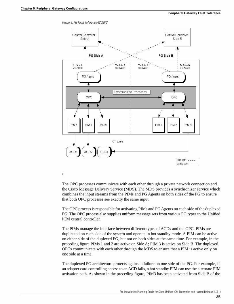
Figure 8: PG Fault ToleranceACD2PG
\
The OPC processes communicate with each other through a private network connection andthe Cisco Message Delivery Service (MDS). The MDS provides a synchronizer service whichcombines the input streams from the PIMs and PG Agents on both sides of the PG to ensurethat both OPC processes see exactly the same input.
The OPC process is responsible for activating PIMs and PG Agents on each side of the duplexedPG. The OPC process also supplies uniform message sets from various PG types to the UnifiedICM central controller.
The PIMs manage the interface between different types of ACDs and the OPC. PIMs areduplicated on each side of the system and operate in hot standby mode. A PIM can be activeon either side of the duplexed PG, but not on both sides at the same time. For example, in thepreceding figure PIMs 1 and 2 are active on Side A; PIM 3 is active on Side B. The duplexedOPCs communicate with each other through the MDS to ensure that a PIM is active only onone side at a time.
The duplexed PG architecture protects against a failure on one side of the PG. For example, ifan adapter card controlling access to an ACD fails, a hot standby PIM can use the alternate PIMactivation path. As shown in the preceding figure, PIM3 has been activated from Side B of the
Pre-installation Planning Guide for Cisco Unified ICM Enterprise and Hosted Release 8.0( 1)
35
Chapter 5: Peripheral Gateway Configurations
Peripheral Gateway Fault Tolerance
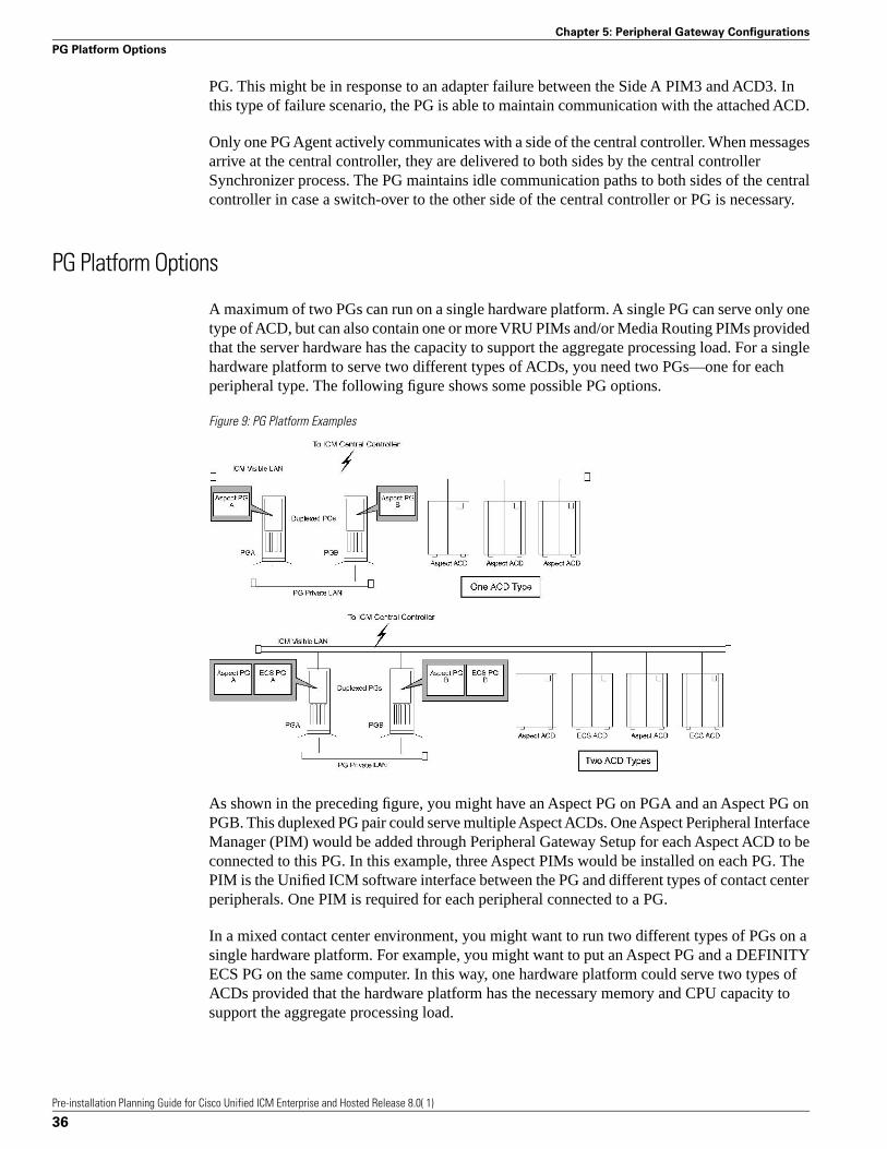
PG. This might be in response to an adapter failure between the Side A PIM3 and ACD3. Inthis type of failure scenario, the PG is able to maintain communication with the attached ACD.
Only one PG Agent actively communicates with a side of the central controller. When messagesarrive at the central controller, they are delivered to both sides by the central controllerSynchronizer process. The PG maintains idle communication paths to both sides of the centralcontroller in case a switch-over to the other side of the central controller or PG is necessary.
PG Platform Options
A maximum of two PGs can run on a single hardware platform. A single PG can serve only onetype of ACD, but can also contain one or more VRU PIMs and/or Media Routing PIMs providedthat the server hardware has the capacity to support the aggregate processing load. For a singlehardware platform to serve two different types of ACDs, you need two PGs—one for eachperipheral type. The following figure shows some possible PG options.
Figure 9: PG Platform Examples
As shown in the preceding figure, you might have an Aspect PG on PGA and an Aspect PG onPGB. This duplexed PG pair could serve multiple Aspect ACDs. One Aspect Peripheral InterfaceManager (PIM) would be added through Peripheral Gateway Setup for each Aspect ACD to beconnected to this PG. In this example, three Aspect PIMs would be installed on each PG. ThePIM is the Unified ICM software interface between the PG and different types of contact centerperipherals. One PIM is required for each peripheral connected to a PG.
In a mixed contact center environment, you might want to run two different types of PGs on asingle hardware platform. For example, you might want to put an Aspect PG and a DEFINITYECS PG on the same computer. In this way, one hardware platform could serve two types ofACDs provided that the hardware platform has the necessary memory and CPU capacity tosupport the aggregate processing load.
Pre-installation Planning Guide for Cisco Unified ICM Enterprise and Hosted Release 8.0( 1)
36
Chapter 5: Peripheral Gateway Configurations
PG Platform Options
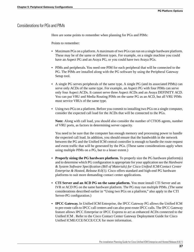
Considerations for PGs and PIMs
Here are some points to remember when planning for PGs and PIMs:
Points to remember:
• Maximum PGs on a platform. A maximum of two PGs can run on a single hardware platform.These may be of the same or different types. For example, on a single machine you couldhave an Aspect PG and an Avaya PG, or you could have two Avaya PGs.
• PIMs and peripherals. You need one PIM for each peripheral that will be connected to thePG. The PIMs are installed along with the PG software by using the Peripheral GatewaySetup tool.
• A single PG serves peripherals of the same type. A single PG (and its associated PIMs) canserve only ACDs of the same type. For example, an Aspect PG with four PIMs can serveonly four Aspect ACDs. It cannot serve three Aspect ACDs and an Avaya DEFINITY ACD.You can put VRU and Media Routing PIMs on the same PG as an ACD, but all VRU PIMsmust service VRUs of the same type.
• Using two PGs on a platform. Before you commit to installing two PGs on a single computer,consider the expected call load for the ACDs that will be connected to the PGs.
Note: Along with call load, you should also consider the number of CTIOS agents, numberof VRU ports, as factors in determining server capacity.
You need to be sure that the computer has enough memory and processing power to handlethe expected call load. In addition, you should ensure that the bandwidth in the networkbetween the PG and the Unified ICM central controller is enough to handle the route requestand event traffic that will be generated by the PGs. (These same considerations apply whenusing multiple PIMs on a PG, but to a lesser extent.)
• Properly sizing the PG hardware platform. To properly size the PG hardware platform(s)and to determine which PG configuration is appropriate for your application see the Hardware& System Software Specification (Bill of Materials) for Cisco Unified ICM/Contact CenterEnterprise & Hosted, Release 8.0(1). Cisco offers standard and high-end PG hardwareplatforms to suit more demanding contact center applications.
• CTI Server and an ACD PG on the same platform. You must install CTI Server and anIVR or ACD PG on the same hardware platform. The PG may run multiple PIMs. (The sameconsiderations described earlier in “Using two PGs on a platform,” also apply to the CTIServer-PG configuration.)
• IPCC Gateway. In Unified ICM Enterprise, the IPCC Gateway PG allows the Unified ICMto pre-route calls to IPCC call centers and can also post-route IPCC calls. The IPCC Gatewayfeature allows IPCC Enterprise or IPCC Express to act as enhanced ACDs connected to theUnified ICM . Refer to the Cisco Contact Center Gateway Deployment Guide for CiscoUnified ICME/CCE/SCCE/CCX for more information.
Pre-installation Planning Guide for Cisco Unified ICM Enterprise and Hosted Release 8.0( 1)
37
Chapter 5: Peripheral Gateway Configurations
PG Platform Options

Standard PG Configuration
In most PG configurations, the PG is located with the ACD at a contact center site. The PGcommunicates with the central controller via the Unified ICM visible network WAN links.These WAN links can be a dedicated circuit, or—if Quality of Service (QoS) is implemented—thecorporate WAN can be used. When Administration & Data Servers are located with PGs andACDs at the contact center site, the WAN links to the central controller can be shared by bothPGs and Administration & Data Servers. If the PG is collocated with the Unified ICM centralcontroller, the PGs connect directly to the Unified ICM visible LAN. The following figureshows an example of a standard PG configuration.
Figure 10: Standard PG Configuration (Duplexed PGs)
Remote ACD and IVR Connection to PGs
Some ACDs allow a remote connection to the Unified ICM Peripheral Gateway. In a remoteACD configuration, the PGs are located at the central site along with the CallRouter, Logger,and NIC. The ACD is located at a remote contact center site.
For information on remote PG support, see the ACD Supplement for the particular ACD.Generally speaking, Alcatel, Aspect, Avaya, NEC, Siemens, Symposium ACDs are supported
Pre-installation Planning Guide for Cisco Unified ICM Enterprise and Hosted Release 8.0( 1)
38
Chapter 5: Peripheral Gateway Configurations
Standard PG Configuration

over the WAN. However, in all cases, you must check with the ACD manufacturer for anyWAN limitations.
The IVR PG can communicate remotely with IVRs via a TCP/IP network. However, you mustensure that the network link between the PG and IVR system provides enough bandwidth tosupport the call load for the VRU.
Multiple PGs Connecting to a Single ACD
It may be necessary to connect multiple PGs to the same ACD. This type of configuration isrequired when multiple Unified ICM customers need to share the same service bureau ACD.In order for this configuration to be possible, the ACD must allow multiple CTI applications toshare its CTI link(s). Support for multiple PG connections varies depending on the ACD platform.Please see the appropriate Cisco Unified ICM software ACD Supplement and contact your ACDvendor to determine the availability of this functionality.
Pre-installation Planning Guide for Cisco Unified ICM Enterprise and Hosted Release 8.0( 1)
39
Chapter 5: Peripheral Gateway Configurations
Multiple PGs Connecting to a Single ACD

Pre-installation Planning Guide for Cisco Unified ICM Enterprise and Hosted Release 8.0( 1)
40
Chapter 5: Peripheral Gateway Configurations
Multiple PGs Connecting to a Single ACD

CTI PlanningCisco CTI software provides an interface between the Unified ICM software and agent desktopand server applications. The CTI software works with a Peripheral Gateway’s ACD and IVRinterface software and associated ACDs to track call events and transactions and forward call-and transaction-related data to an agent’s desktop computer.
Pre-installation planning for CTI involves several tasks:
• Review CTI Server communications and platform options.
• Become familiar with the desktop options available with CTI Server.
• Estimate CTI message traffic.
• Plan fault tolerance for the CTI Server.
• Review ACD support for client control and third-party call control.
This chapter contains the following topics:
• CTI Server, page 41• CTI Server Client Application Models, page 44• CTI Server Network and Database Planning, page 46• CTI Server Message Traffic, page 47• Third-Party Call Control, page 49• ACD Support for Client and Third-Party Call Control, page 51
CTI Server
CTI Server, the basic server component of Cisco CTI, enables the Unified ICM software todeliver agent, call, and customer data in real-time to a server and/or workstation application asevents occur throughout the life of a call. The CTI Server is a software process that runs on a
Pre-installation Planning Guide for Cisco Unified ICM Enterprise and Hosted Release 8.0( 1)
41
Chapter 6

Peripheral Gateway (PG). It is the CTI gateway into the Unified ICM software’s data andservices.
The following figure shows a sample CTI Server system. CTI Servers may be running at oneor several call centers in the enterprise.
Figure 11: CTI Server Overview
One function of the CTI Server is to forward pre-route indications to CTI application servers.Pre-route indications identify the caller and provide CTI applications with other call attributeswhile the call is still in the public or private network (that is, before the call is connected to anagent or IVR resource).
CTI Server also reports call events and agent work state changes as they occur through eachstage of the call flow—from the moment a call arrives at an answering resource (ACD, PBX,IVR), until the caller hangs up. In a desktop application environment, call event information isdelivered to the targeted agent desktop at the same time the call is delivered.
CTI Server Communications
The CTI Server uses TCP/IP Ethernet for communication with clients. Multi-protocol IP routersmay be used to provide connectivity to clients on other types of LANs. The same LAN that isused for the Peripheral Gateway’s visible network interface can also be used for CTIclient-to-server communications.
CTI Server Platform Options
The CTI Server runs on a machine that is also running a Cisco ACD (or VRU) PG process. Theshared platform option is shown in the following figure.
Pre-installation Planning Guide for Cisco Unified ICM Enterprise and Hosted Release 8.0( 1)
42
Chapter 6: CTI Planning
CTI Server
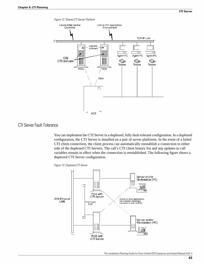
Figure 12: Shared CTI Server Platform
CTI Server Fault Tolerance
You can implement the CTI Server in a duplexed, fully fault-tolerant configuration. In a duplexedconfiguration, the CTI Server is installed on a pair of server platforms. In the event of a failedCTI client connection, the client process can automatically reestablish a connection to eitherside of the duplexed CTI Servers. The call’s CTI client history list and any updates to callvariables remain in effect when the connection is reestablished. The following figure shows aduplexed CTI Server configuration.
Figure 13: Duplexed CTI Server
Pre-installation Planning Guide for Cisco Unified ICM Enterprise and Hosted Release 8.0( 1)
43
Chapter 6: CTI Planning
CTI Server

Cisco CTI Object Server (CTIOS)
CTI Object Server (CTIOS) is a high-performance, scalable, fault-tolerant server-based solutionfor deploying CTI applications. CTIOS serves as a single point of integration for third-partyapplications, including Customer Relationship Management (CRM) systems, data mining, andworkflow solutions.
Configuration data is managed at the server, which helps simplify customization, updates, andmaintenance of CTI applications. Servers can be accessed and managed remotely. Thin-clientand browser-based applications that do not require Cisco software on the desktop can bedeveloped and deployed with CTIOS.
CTIOS incorporates the following major components:
• CTIOS Toolkit
• Client Interface Library
• CTIOS Combo Desktop for Agents and Supervisors
CTIOS is a client of CTI Server. It has a single all-events connection to Cisco CTI Server. Inturn, CTIOS accepts client connections using session, agent, and call interfaces. These interfacesare implemented in .NET, COM, Java, C++, and C, allowing for a wide range of applicationdevelopment uses. The interfaces are used for call control, to access data values, and to receiveevent notifications.
For complete and current information about the number of agents supported for CTIOS andother hardware configurations, see the Hardware & System Software Specification (Bill ofMaterials) for Cisco Unified ICM/Contact Center Enterprise & Hosted, Release 8.0(1).
For new installations, the CTIOS Server should be co-resident with the PG.
For more information on CTIOS, refer to the Cisco Unified ICM Software CTIOS documentset.
CTI Server Client Application Models
You can use either of two client models to integrate call center applications with the UnifiedICM : agent workstation and CTI Bridge.
Agent Workstation (Desktop) Application
In the agent workstation model, the client is an application running on a personal computer onan agent’s desktop. This client is interested in the call data and call events related to a singleagent teleset. The agent workstation application might also be interested in agent state changes.
Pre-installation Planning Guide for Cisco Unified ICM Enterprise and Hosted Release 8.0( 1)
44
Chapter 6: CTI Planning
CTI Server Client Application Models
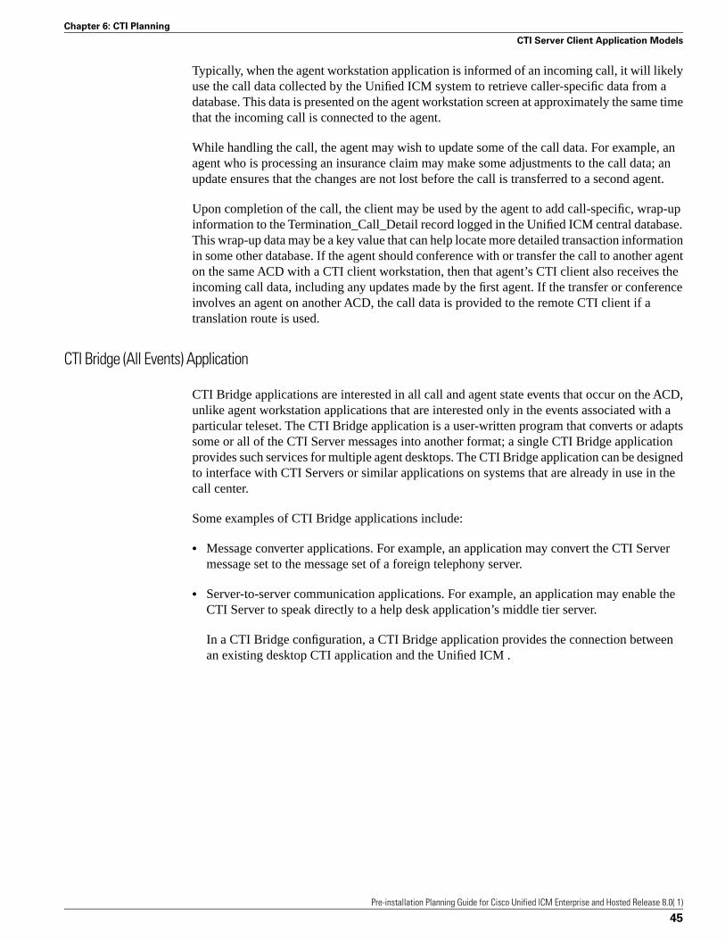
Typically, when the agent workstation application is informed of an incoming call, it will likelyuse the call data collected by the Unified ICM system to retrieve caller-specific data from adatabase. This data is presented on the agent workstation screen at approximately the same timethat the incoming call is connected to the agent.
While handling the call, the agent may wish to update some of the call data. For example, anagent who is processing an insurance claim may make some adjustments to the call data; anupdate ensures that the changes are not lost before the call is transferred to a second agent.
Upon completion of the call, the client may be used by the agent to add call-specific, wrap-upinformation to the Termination_Call_Detail record logged in the Unified ICM central database.This wrap-up data may be a key value that can help locate more detailed transaction informationin some other database. If the agent should conference with or transfer the call to another agenton the same ACD with a CTI client workstation, then that agent’s CTI client also receives theincoming call data, including any updates made by the first agent. If the transfer or conferenceinvolves an agent on another ACD, the call data is provided to the remote CTI client if atranslation route is used.
CTI Bridge (All Events) Application
CTI Bridge applications are interested in all call and agent state events that occur on the ACD,unlike agent workstation applications that are interested only in the events associated with aparticular teleset. The CTI Bridge application is a user-written program that converts or adaptssome or all of the CTI Server messages into another format; a single CTI Bridge applicationprovides such services for multiple agent desktops. The CTI Bridge application can be designedto interface with CTI Servers or similar applications on systems that are already in use in thecall center.
Some examples of CTI Bridge applications include:
• Message converter applications. For example, an application may convert the CTI Servermessage set to the message set of a foreign telephony server.
• Server-to-server communication applications. For example, an application may enable theCTI Server to speak directly to a help desk application’s middle tier server.
In a CTI Bridge configuration, a CTI Bridge application provides the connection betweenan existing desktop CTI application and the Unified ICM .
Pre-installation Planning Guide for Cisco Unified ICM Enterprise and Hosted Release 8.0( 1)
45
Chapter 6: CTI Planning
CTI Server Client Application Models
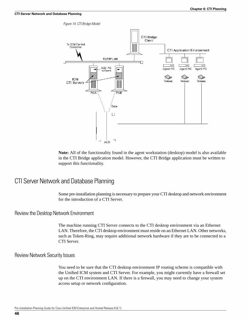
Figure 14: CTI Bridge Model
Note: All of the functionality found in the agent workstation (desktop) model is also availablein the CTI Bridge application model. However, the CTI Bridge application must be written tosupport this functionality.
CTI Server Network and Database Planning
Some pre-installation planning is necessary to prepare your CTI desktop and network environmentfor the introduction of a CTI Server.
Review the Desktop Network Environment
The machine running CTI Server connects to the CTI desktop environment via an EthernetLAN. Therefore, the CTI desktop environment must reside on an Ethernet LAN. Other networks,such as Token-Ring, may require additional network hardware if they are to be connected to aCTI Server.
Review Network Security Issues
You need to be sure that the CTI desktop environment IP routing scheme is compatible withthe Unified ICM system and CTI Server. For example, you might currently have a firewall setup on the CTI environment LAN. If there is a firewall, you may need to change your systemaccess setup or network configuration.
Pre-installation Planning Guide for Cisco Unified ICM Enterprise and Hosted Release 8.0( 1)
46
Chapter 6: CTI Planning
CTI Server Network and Database Planning
Address Desktop Software Roll-out and Distribution Issues
If you are going to be installing the CTIOS or CTI Desktop software components on multipledesktops, you need to create a distribution strategy. For example, you may decide to place thesoftware on a centralized server and allow certain desktops within the enterprise to downloadthe software. In addition, if you use this strategy, and will be installing software across distributedsites, you must ensure that all sites have access to the centralized server.
Select a Well-known Port for CTI Server
A well-known port number identifies CTI Server as an application running in your intranet. AllCTI clients, as well as the system administrator, need to be aware of this well-known portnumber. If you do not want to use CTI Server’s default port numbering scheme, you can choosea well-known port number that fits into your overall network environment. Peripheral GatewaySetup allows you to override the default port settings used to install the CTI Server PGs.
Plan a Fail-over Strategy for CTI Clients
Cisco CTI includes automatic fail-over and recovery mechanisms. Ensure that each CTI clienthas a clear and established network path to a CTI Server in case of a fail-over. For example,you might plan for each CTI client to have access to local and remote CTI Servers.
Develop a Database Strategy
You might have CTI applications that perform database queries to retrieve customer informationfor use in call processing. Some CTI applications might acquire database records “pre-call”(that is, before the call arrives at an agent’s desktop). Other applications might query a databaseimmediately after the call arrives at the agent’s deskset. Plan a strategy for executing databasequeries in the most efficient and timely manner possible.
CTI Server Message Traffic
The CTI Server makes call data available to applications in real time. To accomplish this task,the CTI Server process responds to requests from clients and originates unsolicited messages.All messages share a common message header and use the same set of data types.
The table titled CTI Server Message Categories groups the messages into broad categoriesbased on the nature of the message data.
Table 2: CTI Server Message Categories
DescriptionCategory
Messages related to the establishment and maintenance ofa client connection to the CTI Server. These messages
Session Management
Pre-installation Planning Guide for Cisco Unified ICM Enterprise and Hosted Release 8.0( 1)
47
Chapter 6: CTI Planning
CTI Server Message Traffic

DescriptionCategory
typically happen at client startup, shutdown, and duringauto-recovery.
Messages related to system-level events on the PG (forexample, peripheral offline, loss of PG-to-central controllercommunications).
Miscellaneous
Messages related to call state changes.Call Events
Messages related to agent state changes.Agent Events
Messages related to CTI client modification of call data.Call Data Update
Messages related to the direct control of agent state (forexample, login, logout) as well as control of inbound andoutbound calls.
Client Control
CTI Server imposes varying degrees of message traffic against the PG based on the specificcall center and CTI application environment in which it is deployed. Document a typical callscenario in your CTI application environment, prepare for adequate bandwidth, and order theproper server platform.
Note: For a description of the session management messages, see the latest version of the CiscoUnified ICM Software CTI Server Message Reference Guide.
Documenting a Typical Call Scenario
To estimate CTI Server message traffic, document a typical call scenario in your CTI applicationenvironment. The goal of this exercise is to account for all types of potential message traffic inthe link between the CTI Server and the CTI application environment.
For example, a typical call might be handled as follows:
• The call is pre-routed.
• The call receives a call treatment such as a request to set call data.
• Next, maybe a simple call release, hold, transfer, or post-route request takes place.
• During this time an agent state may have changed (for example, from ready to work ready).
Estimating Required Bandwidth
You need to ensure that you have enough bandwidth in the datacom connection to handle themessage traffic between the CTI Server and the CTI application environment. For example, areyou sure that a 56-Kbps connection will be adequate for your environment?
The call scenario process helps you to estimate the message load and calculate how muchbandwidth is required in the link between the CTI Server and the CTI application environment(for example, 56K, 256K, or more).
Pre-installation Planning Guide for Cisco Unified ICM Enterprise and Hosted Release 8.0( 1)
48
Chapter 6: CTI Planning
CTI Server Message Traffic
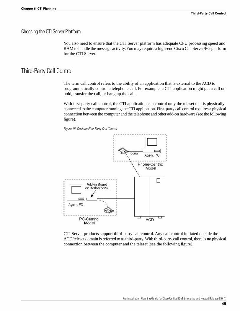
Choosing the CTI Server Platform
You also need to ensure that the CTI Server platform has adequate CPU processing speed andRAM to handle the message activity. You may require a high-end Cisco CTI Server/PG platformfor the CTI Server.
Third-Party Call Control
The term call control refers to the ability of an application that is external to the ACD toprogrammatically control a telephone call. For example, a CTI application might put a call onhold, transfer the call, or hang up the call.
With first-party call control, the CTI application can control only the teleset that is physicallyconnected to the computer running the CTI application. First-party call control requires a physicalconnection between the computer and the telephone and other add-on hardware (see the followingfigure).
Figure 15: Desktop First-Party Call Control
CTI Server products support third-party call control. Any call control initiated outside theACD/teleset domain is referred to as third-party. With third-party call control, there is no physicalconnection between the computer and the teleset (see the following figure).
Pre-installation Planning Guide for Cisco Unified ICM Enterprise and Hosted Release 8.0( 1)
49
Chapter 6: CTI Planning
Third-Party Call Control

Figure 16: Desktop Third-Party Call Control
The desktop CTI application communicates with the Cisco CTI Server over a LAN. The CTIServer in turn communicates with the ACD to send call control requests. In this model, the CTIapplication is not bound to any particular teleset. The CTI application can control any telesetconnected to the ACD and CTI Server.
Note: Most, but not all, ACDs support third-party call control.
Depending on the specific ACD, the client application can perform all or most of the followingtelephony functions:
• Answer/Hang up
• Agent Login and Wrap-up data
• Consultative/Blind Conference
• Consultative/Blind Transfer
• Generate DTMF tones
• Get/Set Agent states
• Get/Set ICM call data (ANI, DNIS, CED, UUI, call vars)
• Hold/Unhold/Swap Hold
• Make a call
• Redirect
Pre-installation Planning Guide for Cisco Unified ICM Enterprise and Hosted Release 8.0( 1)
50
Chapter 6: CTI Planning
Third-Party Call Control

ACD Support for Client and Third-Party Call Control
Different peripheral types implement and support varying levels of CTI functionality. Forexample, a different set of client control requests and call event types may be available dependingon the peripheral type. In addition, there may be other CTI-related restrictions and implementationdifferences based on the type of peripheral. You need to take these differences into accountwhen you write a CTI client application that will interface with third-party switches and devices.
For example,
• The Rockwell Galaxy does not have CTI Server support.
• The Siemens Rolm 9751 CBX does not have CTI Server support, but does support screen-popapplications.
As part of CTI pre-installation planning, you need to review ACD support for client control andthird-party call control.
Pre-installation Planning Guide for Cisco Unified ICM Enterprise and Hosted Release 8.0( 1)
51
Chapter 6: CTI Planning
ACD Support for Client and Third-Party Call Control

Pre-installation Planning Guide for Cisco Unified ICM Enterprise and Hosted Release 8.0( 1)
52
Chapter 6: CTI Planning
ACD Support for Client and Third-Party Call Control

IVR PlanningCisco provides an option for running an interface to Interactive Voice Response (IVR) systems.The IVR interface software allows IVRs to take advantage of Unified ICM call routing features.For example, an IVR can use post-routing capabilities to select targets for calls it needs totransfer. The IVR interface software runs as a process on a standard PG hardware platform. Itallows the Unified ICM to route calls to targets on an IVR and collect data from an IVR for usein call routing, real-time monitoring, and historical reporting. The IVR interface is not specificto a particular IVR system or manufacturer. It is based on an open IVR model. Many IVRsystems support Cisco’s Open IVR Interface Specification, including Unified CVP. For a listof IVRs that support this interface, contact your Cisco representative.
To plan for this IVR option:
• Review the options for integrating IVRs into the Unified ICM system.
• Determine if any IVR programming or application development is necessary.
• Review the Peripheral Gateway platform requirements.
Reviewing IVR Configuration Options
IVRs can be located at the customer’s call center site or in the IXC network. At the call center,the IVR might be connected on the network side of the ACD or “behind” the ACD. In the IXCnetwork, the IVR may be offered as a service by the network provider.
In an Unified ICM configuration that includes an IVR, the ACD is configured so that it cantransfer calls to the IVR. The following figure shows some of the capabilities of the IVR in anUnified ICM system.
Pre-installation Planning Guide for Cisco Unified ICM Enterprise and Hosted Release 8.0( 1)
53
Chapter 7

Figure 17: IVR/ICM Integration Overview
Capabilities of IVR:
1. In most Unified ICM /IVR configurations, calls continued to be Pre-Routed by the UnifiedICM system.
2. When a call is routed to an IVR, the IVR answers the call and interacts with the caller.
3. The IVR may access a host system (for example, a customer profile database) to retrievemore information to help process the call.
4. Often, the caller can get all the information he or she needs through simple interactionwith the IVR. In some cases, however, the IVR needs to transfer the caller to an agent oranother call resource.
5. In some configurations, the IVR can invoke post-routing to select an agent from anywherein the call center enterprise. To do this, the IVR sends a route request to the PG. The PGforwards the request to the Unified ICM system, which responds with a new destinationfor the call. The PG returns the new destination to the IVR. The IVR then signals the ACDor network to transfer the call to the specified destination.
The way in which an IVR is integrated into the Unified ICM system affects the flow of callprocessing and determines the types of data the Unified ICM can collect from the IVR. Forexample, an IVR that has a direct interface to an IVR PG provides the Unified ICM system withdata that can be used in call routing, monitoring, and reporting. A configuration in which theIVR has an interface only to the ACD has more limited capabilities.
Pre-installation Planning Guide for Cisco Unified ICM Enterprise and Hosted Release 8.0( 1)
54
Chapter 7: IVR Planning
Reviewing IVR Configuration Options

You can integrate IVRs into the Unified ICM system in several different ways. Each integrationoption provides a different set of Unified ICM functionality.
Configuration with an ACD PG Only
In this option, the IVR is attached only to the ACD. The ACD, in turn, is attached to a PG. ThePG is running the Cisco peripheral interface software (PG software process) required tocommunicate with the specific type of ACD. There is no direct interface between the IVR andthe Unified ICM system (in other words, an IVR process is not implemented).
Figure 18: Configuration With an ACD PG Only
In this configuration, the IVR must be connected to an ACD that supports post-routing. TheIVR and ACD cooperate so that calls can be transferred from the IVR to the ACD, and thenpost-routed by the ACD via the PG. The PG in this configuration has only the ACD peripheralinterface software. It does not have the IVR interface software. Therefore, it does not providethe IVR with full access to post-routing.
In the preceding figure, the IVR can handle a call in two different ways:
• The IVR can handle the call to completion (for example, if the caller wanted current billinginformation and needed no further assistance, the IVR could complete the call.)
• The IVR can transfer the call to the ACD. The ACD could then use the PG to post-route thecall.
Pre-installation Planning Guide for Cisco Unified ICM Enterprise and Hosted Release 8.0( 1)
55
Chapter 7: IVR Planning
Reviewing IVR Configuration Options
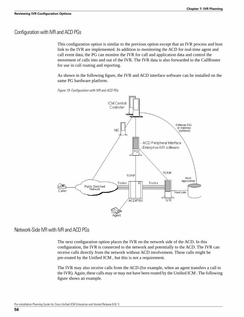
Configuration with IVR and ACD PGs
This configuration option is similar to the previous option except that an IVR process and hostlink to the IVR are implemented. In addition to monitoring the ACD for real-time agent andcall event data, the PG can monitor the IVR for call and application data and control themovement of calls into and out of the IVR. The IVR data is also forwarded to the CallRouterfor use in call routing and reporting.
As shown in the following figure, the IVR and ACD interface software can be installed on thesame PG hardware platform.
Figure 19: Configuration with IVR and ACD PGs
Network-Side IVR with IVR and ACD PGs
The next configuration option places the IVR on the network side of the ACD. In thisconfiguration, the IVR is connected to the network and potentially to the ACD. The IVR canreceive calls directly from the network without ACD involvement. These calls might bepre-routed by the Unified ICM , but this is not a requirement.
The IVR may also receive calls from the ACD (for example, when an agent transfers a call tothe IVR). Again, these calls may or may not have been routed by the Unified ICM . The followingfigure shows an example.
Pre-installation Planning Guide for Cisco Unified ICM Enterprise and Hosted Release 8.0( 1)
56
Chapter 7: IVR Planning
Reviewing IVR Configuration Options
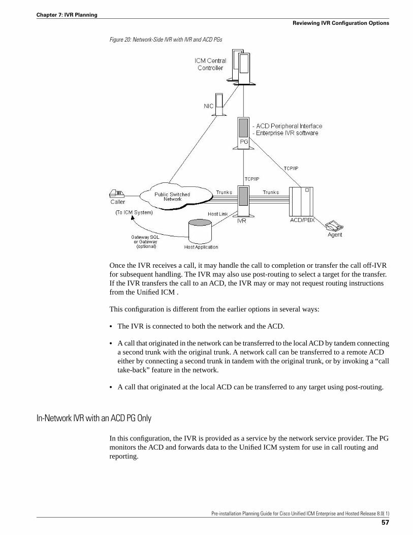
Figure 20: Network-Side IVR with IVR and ACD PGs
Once the IVR receives a call, it may handle the call to completion or transfer the call off-IVRfor subsequent handling. The IVR may also use post-routing to select a target for the transfer.If the IVR transfers the call to an ACD, the IVR may or may not request routing instructionsfrom the Unified ICM .
This configuration is different from the earlier options in several ways:
• The IVR is connected to both the network and the ACD.
• A call that originated in the network can be transferred to the local ACD by tandem connectinga second trunk with the original trunk. A network call can be transferred to a remote ACDeither by connecting a second trunk in tandem with the original trunk, or by invoking a “calltake-back” feature in the network.
• A call that originated at the local ACD can be transferred to any target using post-routing.
In-Network IVR with an ACD PG Only
In this configuration, the IVR is provided as a service by the network service provider. The PGmonitors the ACD and forwards data to the Unified ICM system for use in call routing andreporting.
Pre-installation Planning Guide for Cisco Unified ICM Enterprise and Hosted Release 8.0( 1)
57
Chapter 7: IVR Planning
Reviewing IVR Configuration Options

Figure 21: In-Network IVR with ACD PG Only
When the caller dials the toll-free number, the Unified ICM instructs the network to transferthe call to the network-based IVR. The network IVR then prompts the caller for input. If thecaller requires additional information (such as speaking to an agent), the IVR dials a “hidden”toll-free number. The network then queries the Unified ICM system for a routing destination.The Unified ICM system returns a routing label and the network transfers the call to the specifiedACD and DNIS. An agent at the ACD may handle the call to completion or transfer the call forsubsequent handling.
In-Network IVR with IVR and ACD PGs
In this configuration, the IVR is provided as a service by the network provider. The networktransfers all calls to a destination IVR. The IVR is responsible for handling a call to completionor transferring the call to another resource (for example, an agent at an ACD).
Pre-installation Planning Guide for Cisco Unified ICM Enterprise and Hosted Release 8.0( 1)
58
Chapter 7: IVR Planning
Reviewing IVR Configuration Options

Figure 22: In-Network IVR with IVR and ACD PGs
IVR Transfer Routing Using Third-Party Call Control
In this configuration, the IVR invokes a transfer request to transfer a call to the ACD. The IVRuses a CTI link to the ACD which allows it to set variables in the transfer request (for example,CED, DNIS, CLID, Social Security number, or account number). This configuration is viableonly if the IVR is attached to an ACD that supports post-routing. The following figure providesan example of this configuration.
Figure 23: IVR Transfer Routing with Third-Party Call Control
Pre-installation Planning Guide for Cisco Unified ICM Enterprise and Hosted Release 8.0( 1)
59
Chapter 7: IVR Planning
Reviewing IVR Configuration Options

When the ACD receives the transfer from the IVR, it makes a route request to the PG in orderto conduct an enterprise-wide agent selection. The PG routing client sends a route request tothe CallRouter. The CallRouter passes a response to the PG and on to the ACD. The ACD thentransfers the call to the specified destination.
IVR Programming and Application Development
The Open IVR Interface allows the Unified ICM to see some level of IVR application-specificdata (for example, menu selections). An IVR application developer can use the Open IVRInterface to implement call routing (routing client) and monitoring capabilities.
The IVR routing client allows the IVR to send route requests to the Unified ICM via the PG.These requests can include data variables such as Customer ID and Menu Selections. The UnifiedICM system can use this data to instruct the IVR where to transfer the call. The IVR monitoringinterface allows the application developer to send IVR port and application activity data to theUnified ICM system for use in call routing and reporting.
IVR Peripheral Gateway
The Cisco IVR interface software runs as a logical PG on a standard Peripheral Gateway hardwareplatform. A single PG hardware platform can support a maximum of two logical PGs. A singlePG platform might run one or two IVR PGs. Or it might run an IVR PG and an ACD PG. Forexample, you could have a PG hardware platform that runs an Aspect CallCenter PG and anIVR PG. A logical PG can have PIMs for one type of ACD, plus an IVR PIM. The hardwareplatform must have sufficient capacity to handle the aggregate load from all attached peripherals.
Note: The multi-instance CTIOS configuration supports up to ten logical PGs on a single PGplatform. These PGs are configured as separate customer instances.
In the following figure, a duplexed set of PGs serve both an IVR system and an ACD system.These PGs would be equipped with both ACD and IVR interface software.
Note: The IVR can also be on a System IPCC PG or a IPCC Generic PG.
The IVR Peripheral Gateway can run in simplexed or duplexed configurations. In a duplexedconfiguration, only one side of the PG has an active connection to the IVR at a time.
Note: When multiple IVRs are connected to a PG, IVRs that use poll-based monitoring maynot be mixed with IVRs using any other kind of monitoring.
Pre-installation Planning Guide for Cisco Unified ICM Enterprise and Hosted Release 8.0( 1)
60
Chapter 7: IVR Planning
Reviewing IVR Configuration Options

Figure 24: IVR-to-PG Interface
For information on how IVR systems fit into the Unified ICM data communications networks,see Chapter 10, “Determining the Datacom Requirements” (page 73).
Pre-installation Planning Guide for Cisco Unified ICM Enterprise and Hosted Release 8.0( 1)
61
Chapter 7: IVR Planning
Reviewing IVR Configuration Options

Pre-installation Planning Guide for Cisco Unified ICM Enterprise and Hosted Release 8.0( 1)
62
Chapter 7: IVR Planning
Reviewing IVR Configuration Options
ICM Application Gateway and ICM Gateway SQLPlanningThe Unified ICM Application Gateway and Unified ICM Gateway SQL options allow UnifiedICM to integrate external contact center applications into the Unified ICME . Each of theseoptions involves some pre-installation planning. For example, you may need to prepare hostsystems and databases; review fault tolerance issues; and, in the case of Unified ICM GatewaySQL, plan for data transfer.
This chapter contains the following topics:
• ICM Application Gateway Planning, page 63• ICM Gateway SQL Planning, page 64
ICM Application Gateway Planning
The Unified ICM Application Gateway option allows the Unified ICM system to interface withany external call center application. Within the Unified ICM software, the Unified ICMApplication Gateway feature is implemented as a node in a call routing script. You add a Gatewaynode to a script to instruct the Unified ICM to execute an external application. This allows thescript to evaluate responses from an external application. The Unified ICM can then basesubsequent routing decisions on the results produced by the application.
A typical Unified ICM Application Gateway application might return a variable to the CallRouterthat identifies the caller as having a certain type of account. The script could then use thisinformation to control where and how the call is routed. Optionally, the Unified ICM softwarecan pass the retrieved information to the site that is receiving the call. In this case, certain datasuch as account numbers, dates, billing phone numbers, and addresses are passed along withthe call to an answering resource.
Pre-installation Planning Guide for Cisco Unified ICM Enterprise and Hosted Release 8.0( 1)
63
Chapter 8

Preparing the Host System
To prepare for the Unified ICM Application Gateway option, you must set up the host systemto communicate with the Unified ICM system. This involves configuring the host applicationto listen to a socket on the target Unified ICM machine. You also need to configure a name andport number to be used to connect the host system to the Unified ICM central database. Thesesteps are performed at system installation. However, you can begin preparing the host applicationsahead of time.
During system installation, when connectivity between the Unified ICM system and host systemis established, you need to identify the host system to be queried by entering data in theApplication_Gateway table.
Fault Tolerance
You can configure access to a single host application or duplicate host applications. In a singlehost configuration, configure the same host for both CallRouters (Side A and Side B). The singlehost method provides no protection against host failures; however, it does protect againstconnection failures.
In order to achieve a higher level of fault tolerance in an Unified ICM Application Gatewayapplication, you can connect duplicate host applications to the CallRouter. For example, theSide A and Side B CallRouters can each manage a connection to one of the duplicated hostapplications. Each time a script initiates a request, both CallRouters query their correspondinghost. The CallRouters use the response from the host that responds first. This method is highlyreliable. Even if a host or a connection fails, all query requests are satisfied.
ICM Gateway SQL Planning
The Unified ICM Gateway SQL option allows the CallRouter to query an external SQL Serverdatabase and use the data in call routing.
If you are going to use the Gateway SQL option, you need to review several pre-installationplanning issues:
• First, Unified ICM Gateway SQL requires an additional Database Server hardware platform.
• You also need to be aware of the tasks involved in setting up the external host database andpopulating it with the data you want to use in call routing.
Database Server Platform
The Unified ICM Gateway SQL option requires a host database server. The host database servercan be duplexed in order to maintain Unified ICM fault tolerance. A duplexed Unified ICMGateway SQL system requires two identical host database server platforms. Each host database
Pre-installation Planning Guide for Cisco Unified ICM Enterprise and Hosted Release 8.0( 1)
64
Chapter 8: ICM Application Gateway and ICM Gateway SQL Planning
ICM Gateway SQL Planning

server resides on the same LAN segment as its corresponding Unified ICM CallRouter. Thefollowing figure shows a duplexed Unified ICM system that has a duplexed Unified ICMGateway SQL host database server.
Figure 25: ICM Gateway SQL Duplexed Configuration
Planning for Data Transfer
To prepare an Unified ICM system for Unified ICM Gateway SQL, you need to make severaldecisions:
Decide which data you want to use in the external database. For example, will you be using:
• Customer records?
• Account information?
• Other types of data?
Decide where the data is coming from:
• Another database?
Pre-installation Planning Guide for Cisco Unified ICM Enterprise and Hosted Release 8.0( 1)
65
Chapter 8: ICM Application Gateway and ICM Gateway SQL Planning
ICM Gateway SQL Planning

• A flat file?
• Other sources?
Make a plan to transfer the data to the external database:
• What type of media will you use to transfer the data (tape, disk, network)?
• Will the transferred data be in a certain format (comma-separated values, text file, SQL Serversyntax)?
Configuration Overview
For Unified ICM Gateway SQL, you must set up and configure one or more host databases tofunction with the Unified ICM system.
Configuration considerations:
• Choosing a host database server platform. The host database server must have adequateprocessing power and disk space. Cisco can provide you with specifications for basic andhigh-end host database server platforms.
• Setting up the host database. This includes:
Installing SQL Server
– Creating a database on the host database server platform
– Defining fields and indexes
– Setting up permissions and replication
• Transferring data from a data source. This task involves transferring data to populate thedatabase with the data to be used in call routing (for example, you might want to transfercustomer records to the database).
• Configuring the Unified ICM system to access the host database. This task involves settingup user names and passwords that the Unified ICM system can use to access the data in thehost database.
• Writing test scripts to test the Unified ICM Gateway SQL option. This task involvesmonitoring test scripts that use the Script Editor DB Lookup node. The monitoring resultsare captured and stored in the Route_Call_Detail table to validate that the Unified ICMGateway SQL feature is functioning.
Pre-installation Planning Guide for Cisco Unified ICM Enterprise and Hosted Release 8.0( 1)
66
Chapter 8: ICM Application Gateway and ICM Gateway SQL Planning
ICM Gateway SQL Planning
Planning for ICM PlatformsOnce you have the system sizing recommendations, you can begin to order the appropriatehardware configuration. First, however, you must determine how many Unified ICM nodes youwill need.
The number of servers required in an Unified ICM system depends on the configuration of thecentral controller, PGs, NICs, and other nodes. For example, a duplexed central controllerconfiguration requires additional servers because the CallRouter and Logger are duplicated.
This chapter contains the following topics:
• Determining the Number of Servers Required, page 67• ICM Platform Considerations , page 68• Planning for Historical Data Servers, page 71
Determining the Number of Servers Required
The table titled Sample Server Requirements shows how to determine the number of serversrequired in your system.
The counts of servers in this example are based on an Unified ICM configuration that has thefollowing characteristics:
• The Unified ICM system has a duplexed, geographically distributed central controller (inother words, each central site has a CallRouter and a Logger).
• One side of the central controller (Central Site 1) is located at a call center and consequentlyhas a PG to serve one or more ACDs. The PG is duplexed (two servers) for fault tolerance.
• This Unified ICM installation has three remote call center sites and two Admin sites.
Pre-installation Planning Guide for Cisco Unified ICM Enterprise and Hosted Release 8.0( 1)
67
Chapter 9

Table 3: Sample Server Requirements
Node TypesSites
Administration& Data Serverwith HDS
PG2DB Server1Call/LgrLgrCallRtr
12--11Central Site 1
1---11Central Site 23
-2--------------------Remote CallCenter 1
-2--------------------Remote CallCenter 2
-2--------------------Remote CallCenter 3
1-------------------------Admin Site 1
1-------------------------Admin Site 2
4822Total Nodes:
--------- These servers are not installed at this type of site.Key:
– Not selected as an option in this particular configuration.
ICM Platform Considerations
Hardware & System Software Specification (Bill of Materials) for Cisco Unified ICM/ContactCenter Enterprise & Hosted, Release 8.0(1) contains information on server configurations andprovides examples of supported server platforms.
Processor Utilization
As a general rule for all Unified ICM nodes, processor utilization should be kept below 60percent at the maximum expected call load on the system. This is needed in order to smoothout call request “spikes” as well as to allow enough reserve capacity to perform activities suchas re-synchronization and background cleanup. Non-ICM software can make up a part of the60 percent maximum load. The processor utilization figure (60 percent) covers all softwarerunning on the platform.
In addition to the utilization requirement, it is necessary that no software on the system run ata priority equal to or higher than the Unified ICM software for more than 100 milliseconds inuninterrupted bursts. In other words, the Unified ICM software needs to run on the system atleast as frequently as once every 100 milliseconds. This is usually not a problem unless device
2) Only installed at the central site if that site also serves as a call center or you are using the remote ACD option
1) Required only in ICM Gateway SQL configurations.
3) A second central site is not required in duplexed-collocated Central Controller configurations.
Pre-installation Planning Guide for Cisco Unified ICM Enterprise and Hosted Release 8.0( 1)
68
Chapter 9: Planning for ICM Platforms
ICM Platform Considerations

drivers or other kernel-level software is installed, or process/thread priorities have changedincorrectly.
Paging Requirements
The most time-critical component of the Unified ICM system, the CallRouter node, must notbe delayed due to disk I/O (that is, paging). The only disk I/O that should be occurring on UnifiedICM machines is for log file writes and database I/O. The database I/Os occur on Logger andAdministration & Data Server machines. The simple rule is to provide enough main memoryso that the entire working sets of critical processes remain in memory.
For complete and current information about RAM and other platform requirements, see theHardware & System Software Specification (Bill of Materials) for Cisco Unified ICM/ContactCenter Enterprise & Hosted, Release 8.0(1).
The database platforms (Loggers, Administration & Data Servers, and Unified ICM GatewaySQL machines) should have enough main memory so that all first level index pages are kept inmain memory cache.
Logger Expansion
The Logger platform you order may include a combination of internal and external SCSI harddrives. As your call center enterprise grows, your database requirements will typically grow aswell. You might have more services, skill groups, and routes in your configuration, and youmight be routing more calls each day. This will result in more historical data being stored inthe central database.
When your database requirements change, contact your Unified ICM software support providerto have the storage capacity of the central database increased.
Note: Refer to Hardware & System Software Specification (Bill of Materials) for Cisco UnifiedICM/Contact Center Enterprise & Hosted, Release 8.0(1) for more information on data storagespecifications.
They can allocate more database space after your system is installed by:
• Remotely adding database space (if current disk space allows).
• Installing “hot-plugable” disk drives and configuring the disks while the system is running.
Note: Administration Guide for Cisco Unified ICM Enterprise provides information for managingdatabase space once the Unified ICM system is installed and running.
Planning for Administration & Data Servers
To allow users to monitor current call center activity, the Unified ICM system forwards real-timedata to Administration & Data Servers at selected sites throughout the call center enterprise.The following figure illustrates the real-time architecture of the Unified ICM system.
Pre-installation Planning Guide for Cisco Unified ICM Enterprise and Hosted Release 8.0( 1)
69
Chapter 9: Planning for ICM Platforms
ICM Platform Considerations
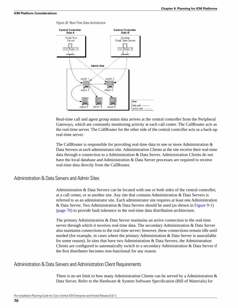
Figure 26: Real-Time Data Architecture
Real-time call and agent group status data arrives at the central controller from the PeripheralGateways, which are constantly monitoring activity at each call center. The CallRouter acts asthe real-time server. The CallRouter for the other side of the central controller acts as a back-upreal-time server.
The CallRouter is responsible for providing real-time data to one or more Administration &Data Servers at each administrator site. Administration Clients at the site receive their real-timedata through a connection to a Administration & Data Server. Administration Clients do nothave the local database and Administration & Data Server processes are required to receivereal-time data directly from the CallRouter.
Administration & Data Servers and Admin Sites
Administration & Data Servers can be located with one or both sides of the central controller,at a call center, or at another site. Any site that contains Administration & Data Servers isreferred to as an administrator site. Each administrator site requires at least one Administration& Data Server. Two Administration & Data Servers should be used (as shown in Figure 9-1)(page 70) to provide fault tolerance in the real-time data distribution architecture.
The primary Administration & Data Server maintains an active connection to the real-timeserver through which it receives real-time data. The secondary Administration & Data Serveralso maintains connections to the real-time server; however, these connections remain idle untilneeded (for example, in cases where the primary Administration & Data Server is unavailablefor some reason). In sites that have two Administration & Data Servers, the AdministrationClients are configured to automatically switch to a secondary Administration & Data Server ifthe first distributor becomes non-functional for any reason.
Administration & Data Servers and Administration Client Requirements
There is no set limit to how many Administration Clients can be served by a Administration &Data Server. Refer to the Hardware & System Software Specification (Bill of Materials) for
Pre-installation Planning Guide for Cisco Unified ICM Enterprise and Hosted Release 8.0( 1)
70
Chapter 9: Planning for ICM Platforms
ICM Platform Considerations

Cisco Unified ICM/Contact Center Enterprise & Hosted, Release 8.0(1) for information aboutrequirements for Distributor and Administration Clients.
Planning for Historical Data Servers
Historical data is stored both as individual call detail records and also rolled up and stored asinterval records. A Administration & Data Server with a Historical Data Server (HDS) storeshistorical data that supports reporting queries. Administration & Data Servers at the site queryhistorical data from the HDS rather than directly from the Logger.
Figure 27: Historical Data Server Architecture
To set up a Historical Data Server, you must configure the Logger to perform historical datareplication. You must also configure the real-time Administration & Data Server to be an HDS.You can then create an HDS database on the real-time distributor.
Information in the real-time feed tells each Administration Client where to obtain historicaldata. If the real-time distributor is a Historical Data Server, then it instructs its clients to gethistorical data from it. Otherwise, it instructs its clients to get historical data from the Logger.
Each Logger can support up to two HDS's. These servers can be configured either as two primarydistributors or with one as a secondary distributor. If these systems are needed to supportreporting requirements, review the "Primary/Secondary Administration & Data ServerDeployment" section of the WebView Installation and Administration Guide to understand allof the factors for consideration before deciding the best deployment strategy for yourorganization. The same fault-tolerant strategy that applies to the real-time Administration &Data Server also applies to the HDS. That is, when the primary HDS fails, other AdministrationClients at the site automatically switch over to use the backup HDS.
HDS Features
The HDS eliminates the performance impact on the central database caused when multipleAdministration & Data Servers need to access the central database to generate reports. In systems
Pre-installation Planning Guide for Cisco Unified ICM Enterprise and Hosted Release 8.0( 1)
71
Chapter 9: Planning for ICM Platforms
Planning for Historical Data Servers

that have multiple remote Administration & Data Servers, the HDS brings Unified ICM historicalreporting data closer to the end user. Each HDS provides a set of database tables. You can setspecific times for retaining data in these tables. These capabilities give you flexibility in settingup reporting capabilities on a site-by-site basis.
The Historical Data Server also provides:
• Greater flexibility in leveraging Internet applications.
• An open interface for data mining and data warehousing applications.
• The ability to host other database tables and have them work with the HDS.
• Improved security and data access capabilities.
The HDS Administration & Data Server requires a high-end platform with a more powerfulCPU, greater disk capacity, and more RAM. For complete and current information on HDSrequirements, see the Hardware & System Software Specification (Bill of Materials) forCisco Unified ICM/Contact Center Enterprise & Hosted, Release 8.0(1).
Pre-installation Planning Guide for Cisco Unified ICM Enterprise and Hosted Release 8.0( 1)
72
Chapter 9: Planning for ICM Platforms
Planning for Historical Data Servers
Determining the Datacom RequirementsThe Unified ICM system needs highly reliable networks to ensure sufficient real-timeresponsiveness and fault tolerance. Because the Unified ICM system is a mission-critical,fault-tolerant system, it must be able to respond quickly when a node goes offline for any reason.Depending on the situation, the Unified ICM system might need to switch communication pathsor activate other nodes to keep the system running without interruption.
In addition to responding to node failures, the Unified ICM system needs to perform diagnosticson failed nodes so they can be returned to service as soon as possible. Often, the Unified ICMdiagnostic procedures take place over a Wide Area Network (WAN).
The Unified ICM system must also be able to respond to route requests from the InterexchangeCarriers (IXCs) within a certain minimum time-out period. For example, the AT&T intelligentcall processing network requires a response from the Unified ICM system within 200 millisecondsof receiving a route request. In a geographically distributed Unified ICM configuration, thismeans that the Unified ICM system must perform communications between the NICs andCallRouters on both sides of the central controller and return a route response all within the 200millisecond time-out period.
This chapter helps you to prepare network facilities for an Unified ICM system installation. Inthis chapter, complete the following tasks:
• Determine requirements for visible and private networking. The Unified ICM networksmust meet certain minimum bandwidth and latency requirements.
• Allocate IP addresses. Assess the IP address requirements for Unified ICM nodes at eachsite in the system.
• Fill out IP address worksheets. Use the worksheets in Chapter 12, “IP Address Worksheets”(page 111)to assign IP addresses.
• Order any additional network hardware. To prepare the network facilities, you may needto order routers, bridges, or cabling.
Pre-installation Planning Guide for Cisco Unified ICM Enterprise and Hosted Release 8.0( 1)
73
Chapter 10

This chapter also covers some of the options for configuring the Unified ICM networks andintegrating them with your existing networks.
This chapter contains the following topics:
• ICM Sites, page 74• The ICM Networks, page 74• Cisco ICM Quality Of Service (QoS), page 81• Active Directory Model, page 88• TCP/IP Configuration, page 88• Central Sites, page 89• Contact Center Sites, page 101
ICM Sites
The Unified ICM system consists of a number of computers, or nodes, which are typicallylocated at more than one site. An Unified ICM system can be distributed among anywhere fromthree to fifty sites or more. Each site might contain one or more nodes. The Unified ICM systemrequires several networks to interconnect nodes within and among the sites.
Unified ICM sites are of three basic types:
• Central sites. Contain one or both sides of the central controller (that is, the CallRouter andLogger) and possibly a separate Network Interface Controller. Central sites can also containAdministration & Data Servers and Peripheral Gateways.
• Contact center sites. Contain one or more Peripheral Gateways (PGs) and possiblyAdministration & Data Servers. Sites also support Agents, phone applications and CTIapplications.
• Admin sites. Contain one or more Administration & Data Servers.
An Unified ICM site might be a combination of any two or more of these. For example, a singlelocation might be both a central site and a contact center site.
The ICM Networks
The Unified ICM system uses three independent communications networks
Following are the ill three independent communications networks:
• Private network. This is a dedicated network that allows specific nodes to communicatewith each other without outside interference. This network carries the data that is necessaryto maintain and restore synchronization between the systems. The private network is not tobe used for any other purpose.
• Visible network. This is a shared network that allows the central controller to communicatewith local and remote nodes. It carries traffic between each side of the synchronized system
Pre-installation Planning Guide for Cisco Unified ICM Enterprise and Hosted Release 8.0( 1)
74
Chapter 10: Determining the Datacom Requirements
ICM Sites

and foreign systems. The visible network may also be used by the fault tolerance softwareas an alternate network to distinguish between node failures and network failures.
• Signaling Access Network. This network connects the Unified ICM system to a carriernetwork or client network. When a SAN is implemented, the Unified ICM system uses theSAN (not the private network) to communicate with the carrier network.
The following figure shows the two sides of the central controller, a contact center site, and anadministrator site. A private WAN links both sides of the duplexed central controller. A visibleWAN links the contact center and administrator sites to each side of the central controller. Nodeswithin each site are linked by a local area network (LAN).
Figure 28: ICM System Network Overview
In the preceding figure, the two sides of the central controller are geographically separated. Thewide area network connections in both the private and visible networks are referred to as WANlinks. WAN links in the Unified ICM system are typically high-availability provisioned circuits.These links must possess extremely low and extremely predictable latency characteristics.
Pre-installation Planning Guide for Cisco Unified ICM Enterprise and Hosted Release 8.0( 1)
75
Chapter 10: Determining the Datacom Requirements
The ICM Networks

Therefore, some types of WAN service cannot be used for WAN links within the Unified ICMsystem (for example, packet routing).
Private and Visible WAN Links
The two sides of the duplexed Unified ICM central controller share a single private networkand are linked via a private WAN link. They also share a visible network which connects thetwo sides via a visible WAN link. To ensure a high level of fault tolerance, the private WANlink and visible WAN links must be independent (that is, they must use different trunks andpossibly even different service providers).
When the two sides of the central controller are co-located, the visible WAN link between thesites is not needed. The standard visible WAN links to remote contact center sites provideadequate connectivity between the two sides. In a co-located central controller configuration,the private network is implemented locally by using Ethernet switches.
Remote contact centers connect to each side of the central controller via the visible network.Each visible WAN link to a contact center must have adequate bandwidth to support PGs andAdministration & Data Servers at the contact center (the bandwidth requirement varies greatlyas the configuration changes, that is, the call load, the number of agents, and so on).
When a contact center is co-located with a side of the central controller, the PGs andAdministration & Data Servers connect to the visible LAN on that side. The PGs andAdministration & Data Servers connect to the other side of the central controller via a visibleWAN link. In such a configuration, a direct visible WAN link between the sides of the centralcontroller is required to ensure adequate connectivity between the two sides. LAN bridges mayoptionally be deployed to isolate PGs from the Administration & Data Server LAN segmentand to enhance protection against LAN outages.
Note: See the section titled Central Sites (page 89), for some examples of co-located centralcontroller configurations.
Signaling Access Networking
The CallRouter machine connects to the IXC signaling network via the Signaling Access Network(SAN). A separate LAN interface card in the CallRouter is dedicated for use just by the SAN.The SAN connects the NICs on each side of the duplexed system to the IXC signaling network.In most cases, the NIC software runs on the CallRouter computer. For clarity, in Figure 10-1(page 75), the NIC is shown as a separate computer installed on the SAN.
A node called the Unified ICM Network Gateway may also be installed on the SAN and usedto interface to some SS7-based networks. The Unified ICM Network Gateway is a dedicatedmachine that provides SS7 protocol handling services.
In Sigtran SS7 networks, Sigtran Gateways may be co-located on the CallRouter machine oron a separate machine. Sigtran Gateways connect to the Sigtran SS7 network using the SCCPUser Adaptation layer (SUA) with Stream Control Transmission Protocol (SCTP) as the networktransport. Sigtran Gateways can serve the following functions, depending on customerrequirements:
Pre-installation Planning Guide for Cisco Unified ICM Enterprise and Hosted Release 8.0( 1)
76
Chapter 10: Determining the Datacom Requirements
The ICM Networks
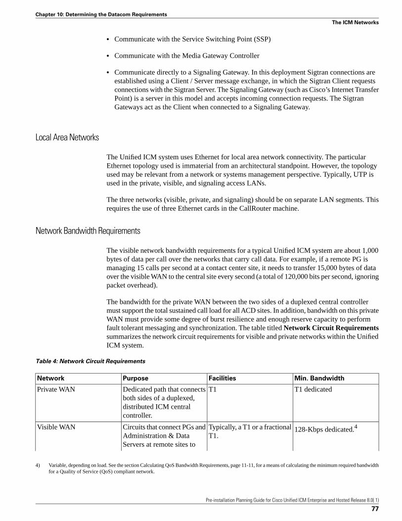
• Communicate with the Service Switching Point (SSP)
• Communicate with the Media Gateway Controller
• Communicate directly to a Signaling Gateway. In this deployment Sigtran connections areestablished using a Client / Server message exchange, in which the Sigtran Client requestsconnections with the Sigtran Server. The Signaling Gateway (such as Cisco’s Internet TransferPoint) is a server in this model and accepts incoming connection requests. The SigtranGateways act as the Client when connected to a Signaling Gateway.
Local Area Networks
The Unified ICM system uses Ethernet for local area network connectivity. The particularEthernet topology used is immaterial from an architectural standpoint. However, the topologyused may be relevant from a network or systems management perspective. Typically, UTP isused in the private, visible, and signaling access LANs.
The three networks (visible, private, and signaling) should be on separate LAN segments. Thisrequires the use of three Ethernet cards in the CallRouter machine.
Network Bandwidth Requirements
The visible network bandwidth requirements for a typical Unified ICM system are about 1,000bytes of data per call over the networks that carry call data. For example, if a remote PG ismanaging 15 calls per second at a contact center site, it needs to transfer 15,000 bytes of dataover the visible WAN to the central site every second (a total of 120,000 bits per second, ignoringpacket overhead).
The bandwidth for the private WAN between the two sides of a duplexed central controllermust support the total sustained call load for all ACD sites. In addition, bandwidth on this privateWAN must provide some degree of burst resilience and enough reserve capacity to performfault tolerant messaging and synchronization. The table titled Network Circuit Requirementssummarizes the network circuit requirements for visible and private networks within the UnifiedICM system.
Table 4: Network Circuit Requirements
Min. BandwidthFacilitiesPurposeNetwork
T1 dedicatedT1Dedicated path that connectsboth sides of a duplexed,
Private WAN
distributed ICM centralcontroller.
128-Kbps dedicated.4Typically, a T1 or a fractionalT1.
Circuits that connect PGs andAdministration & Data
Visible WAN
Servers at remote sites to
4) Variable, depending on load. See the section Calculating QoS Bandwidth Requirements, page 11-11, for a means of calculating the minimum required bandwidthfor a Quality of Service (QoS) compliant network.
Pre-installation Planning Guide for Cisco Unified ICM Enterprise and Hosted Release 8.0( 1)
77
Chapter 10: Determining the Datacom Requirements
The ICM Networks
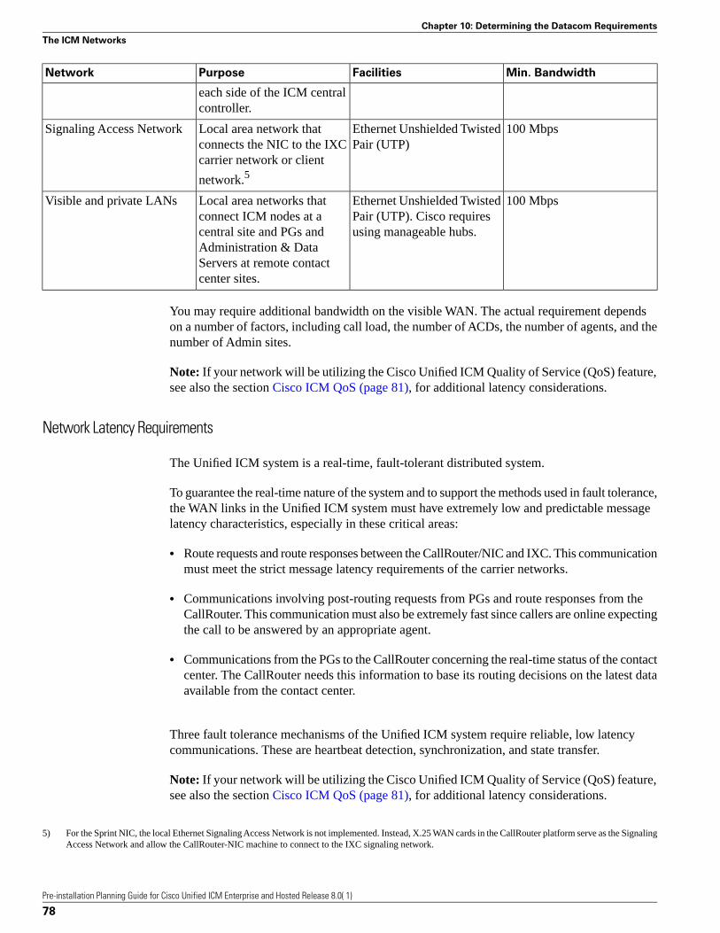
Min. BandwidthFacilitiesPurposeNetwork
each side of the ICM centralcontroller.
100 MbpsEthernet Unshielded TwistedPair (UTP)
Local area network thatconnects the NIC to the IXC
Signaling Access Network
carrier network or client
network.5
100 MbpsEthernet Unshielded TwistedPair (UTP). Cisco requiresusing manageable hubs.
Local area networks thatconnect ICM nodes at acentral site and PGs and
Visible and private LANs
Administration & DataServers at remote contactcenter sites.
You may require additional bandwidth on the visible WAN. The actual requirement dependson a number of factors, including call load, the number of ACDs, the number of agents, and thenumber of Admin sites.
Note: If your network will be utilizing the Cisco Unified ICM Quality of Service (QoS) feature,see also the section Cisco ICM QoS (page 81), for additional latency considerations.
Network Latency Requirements
The Unified ICM system is a real-time, fault-tolerant distributed system.
To guarantee the real-time nature of the system and to support the methods used in fault tolerance,the WAN links in the Unified ICM system must have extremely low and predictable messagelatency characteristics, especially in these critical areas:
• Route requests and route responses between the CallRouter/NIC and IXC. This communicationmust meet the strict message latency requirements of the carrier networks.
• Communications involving post-routing requests from PGs and route responses from theCallRouter. This communication must also be extremely fast since callers are online expectingthe call to be answered by an appropriate agent.
• Communications from the PGs to the CallRouter concerning the real-time status of the contactcenter. The CallRouter needs this information to base its routing decisions on the latest dataavailable from the contact center.
Three fault tolerance mechanisms of the Unified ICM system require reliable, low latencycommunications. These are heartbeat detection, synchronization, and state transfer.
Note: If your network will be utilizing the Cisco Unified ICM Quality of Service (QoS) feature,see also the section Cisco ICM QoS (page 81), for additional latency considerations.
5) For the Sprint NIC, the local Ethernet Signaling Access Network is not implemented. Instead, X.25 WAN cards in the CallRouter platform serve as the SignalingAccess Network and allow the CallRouter-NIC machine to connect to the IXC signaling network.
Pre-installation Planning Guide for Cisco Unified ICM Enterprise and Hosted Release 8.0( 1)
78
Chapter 10: Determining the Datacom Requirements
The ICM Networks

Heartbeat Detection
As part of its fault-tolerant design, the Unified ICM system must be able to quickly respondwhen a component goes offline for any reason (typically, because of a failure in the node or ina network link). Each critical component in the system periodically sends short messages throughthe network to indicate that it is still online. These messages are called heartbeats.
Communicating Unified ICM components send heartbeats to each other at regular intervals. Ifa component fails to receive a heartbeat for five consecutive intervals, it assumes that thecomponent or a network link has failed and it initiates recovery actions. The table titledHeartbeat Configuration lists some of the nodes that send heartbeats, the network on whichthey are sent, and how often they are sent.
Table 5: Heartbeat Configuration
IntervalMediumNode
200 millisecondsSignaling Access NetworkAT&T NIC (or Network Gateway) toCallRouter
100 millisecondsPrivate networkCallRouter to CallRouter
400 millisecondsVisible networkPG to CallRouter
100 millisecondsPG to PG (if duplexed) Private networkPG to PG (if duplexed)
The two sides of a duplexed Unified ICM central controller periodically test each other to seeif the other side is operating correctly. As shown in the table titled Heartbeat Configuration,network latency from CallRouter-to-CallRouter over the private network must support roundtrip messaging of 100 milliseconds. If the bandwidth of the private network is not adequate,packets may need to be fragmented by IP routers in order to prevent long messages (greaterthan 1,500 bytes). Such long messages can delay transmission of User Diagram Protocol (UDP)packets, which indicate that the other side of the central controller is still operating.
Note: A consistent heartbeat or keep-alive mechanism is enforced for both the public and privatenetwork interface. When QoS is enabled on the network interface, a TCP keep-alive messageis sent; otherwise UDP heartbeats are retained.
Another requirement of fault tolerance is that messages cannot be released back to a NIC or PGuntil the other side of the central controller has acknowledged receipt of a copy of the message.Therefore, in order to meet the 200 millisecond response times established by the carriernetworks, and to leave some margin for queuing, a 100 millisecond round trip requirement isestablished.
Heartbeats from a remote PG to the CallRouter must compete with other network traffic on thevisible WAN.
Synchronization
In a duplexed central controller configuration, the private network allows the CallRouters andLoggers on each side to run in a synchronized fashion. This means that the CallRouter and
Pre-installation Planning Guide for Cisco Unified ICM Enterprise and Hosted Release 8.0( 1)
79
Chapter 10: Determining the Datacom Requirements
The ICM Networks

Logger processes on each side of the system receive the same input and generate the sameoutput.
To ensure synchronization, each message intended for the CallRouter or Logger is received bya Synchronizer process that runs on the CallRouter node. The Synchronizer forwards the messageacross the private network to the Synchronizer on the other side. The Synchronizers then removeany duplicates before passing the messages on to the CallRouter processes. If a message isintended for the Logger, the CallRouter passes it along.
Figure 29: Role of Synchronizers
The preceding figure shows how the Synchronizers combine input messages and send themessages in the same order to each side of the central controller. Both CallRouters receive thesame input and generate the same output. The Synchronizers ensure that both sides of the centralcontroller return identical destinations for the same call and write identical data to the databases.
Pre-installation Planning Guide for Cisco Unified ICM Enterprise and Hosted Release 8.0( 1)
80
Chapter 10: Determining the Datacom Requirements
The ICM Networks
State Transfer
The fault tolerance of the Unified ICM system enables nodes to restart after a failure. However,when a failed node restarts, the values of variables in its memory are out-of-date. Before returningthe node to service, the Unified ICM system must copy the values from its peer on the otherside to the recovering node. That is, it must transfer the state of the running machine to therecovering machine. This transfer takes place over the private network.
Note that such state transfers occur after the failure and restart of any synchronized MDS client:PG, Logger, CallRouter, and so on.
Diverse Facilities
The private WAN between central controllers (when the central controllers are geographicallyseparated) and the visible WAN must be on separate facilities. They must use different circuitsand different IP routers. As added protection, you might also want to use diverse routes or evendifferent service providers for the private and visible WAN links. Otherwise, you run the riskof having a single network failure disable both the Unified ICM private and visible WANs.
For example, if the private WAN failed, or a visible WAN link to one side of the central controllerfailed, the Unified ICM system would continue to route calls and function normally. However,if the private WAN and the visible WAN were on the same facilities and failed simultaneously,the fault tolerance of the system would be compromised. In such a scenario, the failure of anysingle node on either side of the central controller would interrupt system processing. Byprovisioning the private WAN and visible WAN on separate facilities, you can eliminate thispotential point of failure.
Cisco ICM Quality Of Service (QoS)
This section describes the Cisco Unified ICM Quality of Service (QoS) feature, and discussesconsiderations to take into account when planning for and deploying Unified ICM networksthat will utilize QoS.
What Is Quality of Service?
Quality of Service is a set of capabilities that enables you to define a level of performance in adata communications network. QoS allows you to create differentiated services for networktraffic, thereby providing better service for selected network traffic. For example, with QoS,you can increase bandwidth for critical traffic, limit bandwidth for non-critical traffic, andprovide consistent network response. This enables you to use expensive network connectionsmore efficiently, lets you establish service level agreements with customers of the network, andeliminates the need of having dedicated leased lines for connection with Unified ICMcomponents.
QoS capabilities enable Unified ICM software to overcome the following architectural limitations:
Pre-installation Planning Guide for Cisco Unified ICM Enterprise and Hosted Release 8.0( 1)
81
Chapter 10: Determining the Datacom Requirements
Cisco ICM Quality Of Service (QoS)

• Unified ICM software requires dedicated leased lines. This means that Unified ICM cannotbe deployed in a converged network, which is more cost-effective and has more transmissioncapacity.
• Lack of a congestion control mechanism over the LAN segment. This is often considerednot important because LAN resources tend to be less costly than WAN resources. However,with the increasing usage of multimedia applications on LANs, delays through LAN switchesdo become problematic. The QoS technology 802.1p tackles these delays.
• Lack of support for Cisco’s AVVID (Architecture for Voice, Video and Integrated Data)enterprise network architecture. AVVID defines the network design principles to optimizethe integration of mission-critical applications in a convergent network environment. QoSis a key technology for AVVID. Unified ICM should be AVVID compliant to be betterdeployed in a Cisco AVVID network.
• Problematic UDP heartbeats. The use of UDP heartbeats creates unnecessary complexity forUnified ICM deployment in firewall and NAT (Network Address Translation) environments.For this reason, UDP heartbeats are replaced by TCP keep-alive messages in Unified ICMQoS implementation.
To implement QoS, you define QoS policies on network devices (routers and switches), andapply the policies to traffic based on DSCP markings, IP precedence, IP address, port, and soon.
QoS primarily comes into play when the amount of traffic through an interface is greater thanthe interface's bandwidth. When the traffic through an interface exceeds the bandwidth, packetsform one or more queues from which the device selects the next packet to send. By setting thequeuing property on a device or interface, you can control how the queues are serviced, thusdetermining the priority of the traffic.
Unified ICM supports DSCP and 802.1p markings for both the public network link (connectingthe PG to the CC) and the private network link (connecting the duplexed sides of PG or CC).
Deploying Cisco ICM QoS
The process of deploying and implementing QoS is a combined effort supported by Cisco SystemEngineers, Unified ICM Deployment Groups, and Cisco Partners.
These Cisco representatives provide customers who plan to deploy QoS with the followingassistance:
• Defining customer requirements. Cisco Professional Services and Cisco Partners utilize theirhistorical knowledge of the customer’s Unified ICM deployment, and QoS bandwidthcalculation tools (see the section Calculating QoS Bandwidth Requirements (page 84)), toassess these requirements.
• Reviewing the Unified ICM portion of the customer’s QoS migration plan.
• Meeting with the customer to prepare a statement of work that defines the level of supportCisco will provide.
Pre-installation Planning Guide for Cisco Unified ICM Enterprise and Hosted Release 8.0( 1)
82
Chapter 10: Determining the Datacom Requirements
Cisco ICM Quality Of Service (QoS)

Meeting with the customer to prepare a statement of work that defines the level of support Ciscowill provide.
Alongside these steps, there are the following tasks to consider when planning to implement aQoS-compliant network in your Unified ICM environment.
• Where to mark traffic
• Determining QoS markings.
• Projecting bandwidth requirements.
• Installing Microsoft Packet Scheduler (optional).
• Installing and configuring 802.1p-capable network components (optional).
• Configuring QoS on IP routers.
Where to Mark Traffic
In planning QoS, a question often arises about where to mark traffic, in the application or at thenetwork edge. Marking traffic in the application saves the access lists for classifying traffic inIP routers/switches, and it may be the only option if traffic flows can not be differentiated byIP address, port and/or other TCP/IP header fields. As mentioned earlier, Unified ICM currentlysupports DSCP markings on the visible network connection between the central controller andthe PG, as well as on the private network connection between duplexed sides of the Router orPG. Additionally, when deployed with Windows Packet Scheduler, it offers shaping and 802.1p.
Traffic can also be marked or remarked in edge IP routers/switches if it is not marked at UnifiedICM servers, or if the QoS trust is disabled. QoS trust may be disabled in an attempt to preventnonpriority users in the network from falsely setting the DSCP or 802.1p values of their packetsto inflated levels so that they receive priority service. For classification criteria definitions onedge routers and switches, refer to the tables titled Public Network Traffic Marking (default)and Latency Requirements and Private Network Traffic Marking (default) and LatencyRequirements in the next section.
Determining QoS Markings
The default Unified ICM QoS markings are set in compliance with Cisco AVVIDrecommendations (but can be overwritten if necessary). See Cisco AVVID Solution IP TelephonyQoS Classification for details about Cisco AVVID packet classifications.
Before QoS implementation, IP-based prioritization is used to provide two externally visiblepriority levels: high and non-high. Internally, however, there are three different priorities forapplication messages: high, medium, and low. In the public network, medium priority messagesare sent through the same high IP connection as the high priority messages; yet in the privatenetwork, they are sent through the non-high IP connection.
Pre-installation Planning Guide for Cisco Unified ICM Enterprise and Hosted Release 8.0( 1)
83
Chapter 10: Determining the Datacom Requirements
Cisco ICM Quality Of Service (QoS)

The tables titled Public Network Traffic Marking (default) and Latency Requirements andPrivate Network Traffic Marking (default) and Latency Requirements list the IP addressand port, latency requirement, default marking under each priority for the public networkconnection and the private network connection respectively.
Table 6: Public Network Traffic Marking (default) and Latency Requirements
DSCP / 802.1p MarkingLatency RequirementIP Address and PortPriority
AF31 / 3200 msPublic high IP and highpriority connection port
High
AF31 / 31,000 msPublic high IP and mediumpriority connection port
Medium
AF11 / 15 secondsPublic non-high IP and lowpriority connection port
Low
Table 7: Private Network Traffic Marking (default) and Latency Requirements
DSCP / 802.1p MarkingLatency RequirementIP Address and PortPriority
AF31 / 3100 ms (50ms preferred)Private high IP and highpriority connection port
High
AF11 / 11,000 msPrivate non-high IP andmedium priority connectionport
Medium
AF11 / 11,000 msPrivate non-high IP and lowpriority connection port
Low
Note:
• Microsoft Packet Scheduler supports at most two marking levels excluding best effort, andtherefore the medium priority traffic is either marked same as the high priority traffic (inpublic network) or marked same as the low priority (in private network). This is similar tothe IP-based prioritization approach and no priority level is lost from the network perspective.When Packet Scheduler is bypassed, however, three marking levels are available and themedium priority messages can be marked differently.
• Cisco makes the QoS marking recommendation for Call-Signaling traffic to DSCP CS3because Class-Selector code points, defined in RFC 2474, are not subject to markdown andaggressive dropping as Assured Forwarding Per-Hop Behaviors are. Some Cisco IP Telephonyproducts already have begun transitioning to DSCP CS3 for Call-Signaling marking. Duringthis interim period, both code points (CS3 and AF31) should be reserved for Call-Signalingmarking until the transition is complete. The Unified ICM QoS markings are configurablethrough the Peripheral Gateway or Web setup and the default Assured Forwarding code pointscan be replaced with the Class-Selector code points to fit into the existing QoS infrastructure.
Calculating QoS Bandwidth Requirements
Although QoS alleviates bandwidth usage and increases network throughput, network congestionis still unavoidable unless sufficient physical bandwidth is available along the path. For UnifiedICM , the bandwidth requirement at each priority is a function of traffic volume and latency
Pre-installation Planning Guide for Cisco Unified ICM Enterprise and Hosted Release 8.0( 1)
84
Chapter 10: Determining the Datacom Requirements
Cisco ICM Quality Of Service (QoS)

requirement. It varies greatly for Unified ICM systems depending on factors such as call load,traffic composition, call context information, and configuration settings.
Cisco provides the following QoS bandwidth calculators and sizing worksheets to help CiscoSystem Engineers, Unified ICM Deployment Groups, and Cisco Partners project traffic volumeas well as bandwidth requirement.
• ACD/CallManager PG to CC Bandwidth Calculator.
• VRU PG to CC Bandwidth Calculator.
• Router Private Link Sizing Worksheet.
• PG Private Link Sizing Worksheet.
Note:
• The network administrator should clearly understand the bandwidth requirement of UnifiedICM flows under each priority and factor it in the bandwidth definition of QoS policiesconfigured on network routers/switches.
• Unified ICM applications are not RSVP (Resource Reservation Protocol) aware and thereforeIntServ (Integrated Service) is not supported. If Packet Scheduler is used, the QoS bandwidthreservations are only made within the local box for the purpose of shaping; no reservationsare made in the network.
Installing Microsoft Packet Scheduler
Note: The Unified ICM DSCP markings can be done with or without Packet Scheduler. Ciscorecommends that you do not use Packet Scheduler unless: 1. Bandwidth requirements are clearlyunderstood and correctly configured, and 2. the convergent network link is occasionally congestedand shaping Unified ICM traffic at the source can be helpful.
Warning: While using the Microsoft Packet Scheduler does provide shaping and 802.1pfeatures, there are significant risks when using this option, as follows: 1. Multiple defectshave been submitted to Microsoft. Currently, some fixes are have been released byMicrosoft, but some have not. 2. If the shaping bandwidth is configured too low, PacketScheduler may introduce excessive delay and as a result it may cause timed-out calls,queue overflows and buffer exhaustion. 3. Shaping at the Unified ICM server may neitherbe necessary or helpful given that the LAN is rarely the bottleneck of communicationsover WAN and a QoS-enabled network is more capable of shaping/queuing/policing trafficbased on the resource usage.
Microsoft Packet Scheduler is a key component in creating the Windows Server 2003 QoSsolution. It regulates how much data a given flow is allowed, when those packets are put ontothe network, and in which order such packets (those ready for transmission) are sent.
The Packet Scheduler installation is not required for Unified ICM . However, some benefit maybe gained from the following:
Pre-installation Planning Guide for Cisco Unified ICM Enterprise and Hosted Release 8.0( 1)
85
Chapter 10: Determining the Datacom Requirements
Cisco ICM Quality Of Service (QoS)

• The Packet Scheduler’s shaping functionality mitigates the burst nature of Unified ICMtransmissions by smoothing transmission peaks over a given period of time, and therebysmoothing out network usage to affect a more steady use of the network.
• 802.1p tagging on Windows Server 2003 is available only if the Packet Scheduler is installed.Without the use of 802.1p, there is no physical guarantee that any prioritized data transmissionswill receive a better service than best-effort transmissions receive in the LAN segment.
To install Microsoft Packet Scheduler, perform the following steps on both the CallRoutermachines and the PG machines.
Note: All current TCP connections are terminated when the Packet Scheduler is installed.Therefore, even though a reboot of the machine is not required when the Packet Scheduler isinstalled, current TCP connections are terminated. You should not install the Packet Schedulerif important connections are in progress.
To install Microsoft Packet Scheduler
Perform the following steps:
Step 1 Open Network and Dial-up Connections.
Step 2 Right click the Network Connection (Public Visible) on which you want to install the QoSPacket Scheduler. Select Properties.
Step 3 Click Install. The Select Network Component Type dialog box appears.
Step 4 Select Service and click Add. The Select Network Service dialog box appears.
Step 5 Select QoS Packet Scheduler. Click OK to begin the installation process.
Installing and Configuring 802.1p-Capable Components
Note: 802.1p is optional. However, see the section Installing Microsoft Packet Scheduler, page11-17, for reasons why you might want to use it.
802.1p expresses priority class by setting three bits in the Layer 2 MAC header, whose binaryvalues 0 through 7 represent eight distinct priority classes (named as Class of Service). ForUnified ICM , the default 802.1p settings are compliant with Cisco AVVID recommendations.Specifically, the high and medium traffic uses the value of 3, and the low priority traffic usesthe value of 1. See Cisco AVVID Solution IP Telephony QoS Classification for details aboutCisco AVVID packet classifications.
If you wish to enable 802.1p marking capabilities as part of your QoS implementation, youmust perform the following tasks:
• Install and enable Microsoft Packet Scheduler, as discussed in the section Installing MicrosoftPacket Scheduler (page 85).
Pre-installation Planning Guide for Cisco Unified ICM Enterprise and Hosted Release 8.0( 1)
86
Chapter 10: Determining the Datacom Requirements
Cisco ICM Quality Of Service (QoS)

• Install 802.1p-capable NICs in the QoS-enabled Unified ICM computers (the Router and thePG)
• Enable 802.1p on the NICs, through the Advanced tab on the NIC Properties screen. This isdone by enabling a selection most often referred to as QoS Packet Tagging.
• Install 802.1p-capable switches on the LAN segment.
• Configure 802.1p-capable switches and coordinate their configuration with the settings onthe Router and/or the PG.
Note: You should install NIC cards before you install Unified ICM software. If you add aNIC card after you install Unified ICM software, you will need to reinstall Unified ICMsoftware.
Refer to Cisco AVVID Network Infrastructure Enterprise Quality of Service Design fordetails about AVVID-Enabled campus network design, switch selection, and QoSconfiguration commands.
Configuring QoS on IP Routes
See Cisco AVVID Network Infrastructure Enterprise Quality of Service Design for details aboutAVVID-Enabled WAN design, router selection, and QoS configuration commands.
Additional Tasks
This section briefly discusses a few additional tasks that you need to perform, after thedeployment tasks listed in the previous sections, to ensure that your QoS-enabled network runscorrectly and efficiently.
ICM QoS Setup
Refer to the Installation Guide for Cisco Unified ICM/Contact Center Enterprise & Hosted fordetails about Unified ICM QoS setup.
Performance Monitoring
You can use the Windows Performance Monitor to track the performance counters associatedwith QoS-enabled connections. Refer to the Administration Guide for Cisco Unified ICM/ContactCenter Enterprise & Hosted for information on using the Windows Performance Monitor.
Note: Depending on your operating system version, this tool may be named System Monitor
For More Information on QoS
The following are Cisco documents that contain additional information on QoS.
Pre-installation Planning Guide for Cisco Unified ICM Enterprise and Hosted Release 8.0( 1)
87
Chapter 10: Determining the Datacom Requirements
Cisco ICM Quality Of Service (QoS)
You can access most Cisco documentation from the Cisco corporate website at http://www.cisco.com
• Cisco IP Contact Center Enterprise Edition Solution Reference Network Design (SRND)
• Cisco AVVID Network Infrastructure Overview
• Cisco AVVID Network Infrastructure Enterprise Quality of Service Design
• Cisco AVVID Solution: IP Telephony QoS Classification
• Planning for Quality of Service
• Quality of Service Networking
• Cisco IP Telephony QoS Design Guide
Active Directory Model
Microsoft Windows Active Directory provides a central repository for managing networkresources. Unified ICM software uses Active Directory services to control users' access rightsto perform setup, configuration, and reporting tasks. Active Directory services also grantpermissions for different components of Unified ICM software to interact; for example, it grantspermissions for a Distributor to read the Logger database.
Unified ICME supports both Windows 2003 and Windows 2008 Active Directory domains.Native mode is required. Unified ICM user configuration data is stored in Active DirectoryOrganizational Units (OU).
For more information see the Staging Guide for Cisco Unified ICM/Contact Center Enterprise& Hosted, Release 8.x(y).
TCP/IP Configuration
To set up IP addresses for Windows Server 2003 nodes, use the TCP/IP Properties dialog box.To display this dialog box, go to the Windows Server 2003 Start menu and choose Settings >Network and Dialup Connections > Local Area Connection. In the Local Area ConnectionStatus window, click on Properties. Select Internet Protocol (TCP/IP) and click on Properties.
Select “Use the following IP address.” Enter the IP address and click OK. To enter additionalIP addresses, open the TCP/IP Properties window again and click Advanced. The AdvancedTCP/IP Settings window allows you to enter additional IP addresses.
Pre-installation Planning Guide for Cisco Unified ICM Enterprise and Hosted Release 8.0( 1)
88
Chapter 10: Determining the Datacom Requirements
Active Directory Model

Central Sites
Each side of the central controller includes the CallRouter, Logger, and Network InterfaceController (NIC). These may be on three separate nodes, two nodes, or a single node. Althoughthe NICs are indicated as separate nodes for clarity, in fact a NIC is implemented as a processwithin the CallRouter node. The two sides of the central controller may be at two differentcentral sites as shown in the following figure.
Figure 30: Geographically Distributed Central Controller
The private network carries Unified ICM system traffic between the nodes on one side of thecentral controller and between the nodes on both sides of the system. The traffic between thetwo sides of the central controller consists of synchronization and state transfer messagingbetween the CallRouters and Loggers. Most communications between the CallRouter and Loggeron one side take place over the private network.
The private WAN link (see the preceding figure) is critical to the overall responsiveness of theUnified ICM system. First, it must provide sufficient bandwidth to handle simultaneoussynchronizer and state transfer traffic. It must also have enough bandwidth left over in caseadditional data must be transferred as part of a recovery operation. Since the private WAN linkis the only link that carries central controller synchronization and state transfer traffic, you maywant to provision backup service of some kind as a contingency for network outages.
The IP routers in the private network always use traffic prioritization, and frequently use IPfragmentation, to ensure that high priority Unified ICM system traffic does not experience
Pre-installation Planning Guide for Cisco Unified ICM Enterprise and Hosted Release 8.0( 1)
89
Chapter 10: Determining the Datacom Requirements
Central Sites

excessive queuing delay. Alternately, both sides of the central controller may be co-located ata single site as shown in the following figure.
Figure 31: Collocated Central Controller
In a co-located central controller configuration, Ethernet switches separate the Side A and SideB private Ethernet LANs for fault tolerance. This private network bridge replaces the privateWAN link. A visible network bridge also connects the Side A and Side B visible networks.
The Visible Network
Each central site has a visible network that connects nodes within that site. To allowcommunication between sites, each side of the central controller must have one IP router on itsvisible LAN.
Note: When a Peripheral Gateway is co-located with one side of a duplexed, geographicallydistributed central controller, you must have a direct connection between the visible WAN IProuters at the two central sites. This ensures that there is adequate visible network connectivitybetween the sides of the central controller.
The IP router requires a single address on the LAN. It also requires that you define a static routeon the IP router for each contact center’s visible LAN and for each administrator site’s visibleLAN.
Pre-installation Planning Guide for Cisco Unified ICM Enterprise and Hosted Release 8.0( 1)
90
Chapter 10: Determining the Datacom Requirements
Central Sites
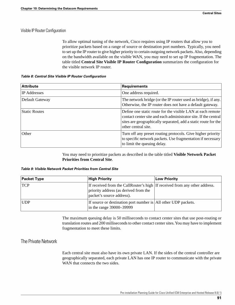
Visible IP Router Configuration
To allow optimal tuning of the network, Cisco requires using IP routers that allow you toprioritize packets based on a range of source or destination port numbers. Typically, you needto set up the IP router to give higher priority to certain outgoing network packets. Also, dependingon the bandwidth available on the visible WAN, you may need to set up IP fragmentation. Thetable titled Central Site Visible IP Router Configuration summarizes the configuration forthe visible network IP router.
Table 8: Central Site Visible IP Router Configuration
RequirementsAttribute
One address required.IP Addresses
The network bridge (or the IP router used as bridge), if any.Otherwise, the IP router does not have a default gateway.
Default Gateway
Define one static route for the visible LAN at each remotecontact center site and each administrator site. If the central
Static Routes
sites are geographically separated, add a static route for theother central site.
Turn off any preset routing protocols. Give higher priorityto specific network packets. Use fragmentation if necessaryto limit the queuing delay.
Other
You may need to prioritize packets as described in the table titled Visible Network PacketPriorities from Central Site.
Table 9: Visible Network Packet Priorities from Central Site
Low PriorityHigh PriorityPacket Type
If received from any other address.If received from the CallRouter’s highpriority address (as derived from thepacket’s source address).
TCP
All other UDP packets.If source or destination port number isin the range 39000–39999
UDP
The maximum queuing delay is 50 milliseconds to contact center sites that use post-routing ortranslation routes and 200 milliseconds to other contact center sites. You may have to implementfragmentation to meet these limits.
The Private Network
Each central site must also have its own private LAN. If the sides of the central controller aregeographically separated, each private LAN has one IP router to communicate with the privateWAN that connects the two sides.
Pre-installation Planning Guide for Cisco Unified ICM Enterprise and Hosted Release 8.0( 1)
91
Chapter 10: Determining the Datacom Requirements
Central Sites
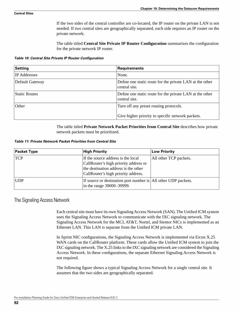
If the two sides of the central controller are co-located, the IP router on the private LAN is notneeded. If two central sites are geographically separated, each side requires an IP router on theprivate network.
The table titled Central Site Private IP Router Configuration summarizes the configurationfor the private network IP router.
Table 10: Central Site Private IP Router Configuration
RequirementsSetting
None.IP Addresses
Define one static route for the private LAN at the othercentral site.
Default Gateway
Define one static route for the private LAN at the othercentral site.
Static Routes
Turn off any preset routing protocols.Other
Give higher priority to specific network packets.
The table titled Private Network Packet Priorities from Central Site describes how privatenetwork packets must be prioritized.
Table 11: Private Network Packet Priorities from Central Site
Low PriorityHigh PriorityPacket Type
All other TCP packets.If the source address is the localCallRouter’s high priority address or
TCP
the destination address is the otherCallRouter’s high priority address.
All other UDP packets.If source or destination port number isin the range 39000–39999.
UDP
The Signaling Access Network
Each central site must have its own Signaling Access Network (SAN). The Unified ICM systemuses the Signaling Access Network to communicate with the IXC signaling network. TheSignaling Access Network for the MCI, AT&T, Nortel, and Stentor NICs is implemented as anEthernet LAN. This LAN is separate from the Unified ICM private LAN.
In Sprint NIC configurations, the Signaling Access Network is implemented via Eicon X.25WAN cards on the CallRouter platform. These cards allow the Unified ICM system to join theIXC signaling network. The X.25 links to the IXC signaling network are considered the SignalingAccess Network. In these configurations, the separate Ethernet Signaling Access Network isnot required.
The following figure shows a typical Signaling Access Network for a single central site. Itassumes that the two sides are geographically separated.
Pre-installation Planning Guide for Cisco Unified ICM Enterprise and Hosted Release 8.0( 1)
92
Chapter 10: Determining the Datacom Requirements
Central Sites
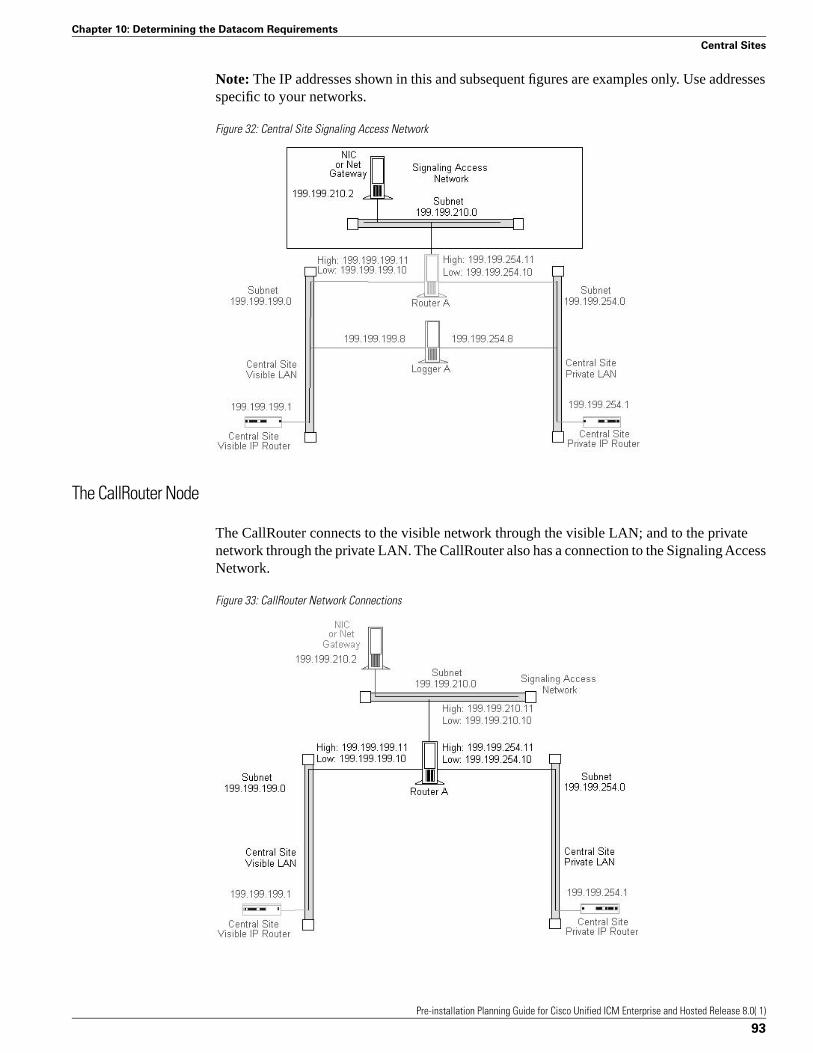
Note: The IP addresses shown in this and subsequent figures are examples only. Use addressesspecific to your networks.
Figure 32: Central Site Signaling Access Network
The CallRouter Node
The CallRouter connects to the visible network through the visible LAN; and to the privatenetwork through the private LAN. The CallRouter also has a connection to the Signaling AccessNetwork.
Figure 33: CallRouter Network Connections
Pre-installation Planning Guide for Cisco Unified ICM Enterprise and Hosted Release 8.0( 1)
93
Chapter 10: Determining the Datacom Requirements
Central Sites

As shown in the preceding figure, the CallRouter requires two addresses on the visible LAN;two addresses on the private LAN; and two addresses on the signaling access LAN. This allowsthe Unified ICM system to separate high-priority network traffic from low-priority traffic.
The table titled CallRouter Visible Network Configuration summarizes the visible networkconfiguration for the CallRouter.
Table 12: CallRouter Visible Network Configuration
RequirementsSetting
Two required: one for high priority data; one for low(normal) priority data. Note that only one address is requiredif you are using QoS.
IP Addresses
Visible network IP router.Default Gateway
None.Static Routes
Preferred and alternate DNS server. See Active DirectoryModel, page 11-21.
Other
The table titled CallRouter Private Network Configurationsummarizes the private networkconfiguration for the CallRouter.
Table 13: CallRouter Private Network Configuration
RequirementsSetting
Two required: one for high priority data; one for low(normal) priority data.
IP Addresses
None. (The default gateway is on the visible LAN.)Default Gateway
If the sides of the central controller are geographicallyseparated, define one static route for the subnet address ofthe private LAN on the other side of the central controller.
Static Routes
Disable Windows Server 2003 networking on the privateLAN.
Other
Note: Instructions on disabling Windows Server 2003 networking on the private LAN appearlater in this section.
The table titled CallRouter Signaling Access LAN Configuration summarizes the SignalingAccess Network configuration for the CallRouter.
Table 14: CallRouter Signaling Access LAN Configuration
RequirementsSetting
Two may be required, the second functioning as aserviceability interface for your Unified ICM serviceprovider.
IP Addresses
None.Default Gateway
None.Static Routes
Pre-installation Planning Guide for Cisco Unified ICM Enterprise and Hosted Release 8.0( 1)
94
Chapter 10: Determining the Datacom Requirements
Central Sites
RequirementsSetting
Disable Windows Server 2003 networking on the SignalingAccess Network.
Other
Disabling Windows 2000 Server and Windows Server 2003 Networking
You need to disable network bindings for the private LAN adaptor on machines that connectto the Unified ICM private network.
You can disable Windows 2000 Server and Windows Server 2003 networking on the privateLAN interface through the Network and Dial-up Connections window. Right click on the MyNetwork Places icon on the Windows 2000 Server or 2003 desktop. The Network and Dial-upConnections window appears. (Optionally, you can right-click on the My Computer icon, selectExplore, then right click on My Network Places and select Properties.)
Choose Advanced > Advanced Settings to display the Advanced Settings window:
Figure 34: Advanced Settings
Make sure that the visible network connection appears first in the list, followed by the privatenetwork connection. You can change the order in which the network connections appear byusing the arrows on the right side of the window. Select the private network connection anddisable both “File and Printer Sharing for Microsoft Networks” and “Client for MicrosoftNetworks.”
The Logger Node
The Logger can be on the same node as the CallRouter, or it can be a separate node.
Pre-installation Planning Guide for Cisco Unified ICM Enterprise and Hosted Release 8.0( 1)
95
Chapter 10: Determining the Datacom Requirements
Central Sites

Figure 35: CallRouter and Logger Combination
If the CallRouter and Logger are on the same node, then the Logger has no specific requirements;it uses low priority addresses defined for the node on the visible and private networks. If thetwo are on separate nodes, then the Logger requires its own connections to both the visible andprivate LANs.
Figure 36: Logger as a Separate Node
In addition to the IP addresses shown, the Logger node may require two additional addresseson the visible network. These addresses allow for dial-in connections by your Unified ICMsupport provider’s Distributed Diagnostic and Service Network (DDSN). The table titled LoggerVisible Network Configuration summarizes the visible network connections for the Logger.
Pre-installation Planning Guide for Cisco Unified ICM Enterprise and Hosted Release 8.0( 1)
96
Chapter 10: Determining the Datacom Requirements
Central Sites

Table 15: Logger Visible Network Configuration
RequirementsSetting
TThree addresses may be required: one for normal data;two more for DDSN dial-up connections.
IP Addresses
Visible network IP router.Default Gateway
None.Static Routes
Preferred and alternate DNS server. See Active DirectoryModel (page 88).
Other
The table titled Logger Private Network Configuration summarizes the private networkconfiguration for the Logger.
Table 16: Logger Private Network Configuration
RequirementsSetting
One address required.IP Addresses
None. (The default gateway is on the visible LAN.)Default Gateway
If the two sides of the central controller are geographicallyseparated, define one static route for the subnet address ofthe private LAN for the other side of the central controller.
Static Routes
Disable Windows 2000 Server or Windows Server 2003networking on the private LAN interface. (See Disabling
Other
Windows 2000 Server and Windows Server 2003Networking, (page 95) for more information.)
If the Logger is on the same computer as the CallRouter, then the visible and private networkIP configuration for the CallRouter is all that is required.
If the Logger is a separate node, you must disable networking on the private LAN interface (aswas required for the CallRouter).
Define a static route in ICMEXEC.BAT, as for the CallRouter.
Optional Database Server Platform
If you order the Cisco Unified ICM Gateway SQL option, you need to set up an additional SQLServer database platform. The database server requires one IP address and one connection tothe Unified ICM visible network.
Pre-installation Planning Guide for Cisco Unified ICM Enterprise and Hosted Release 8.0( 1)
97
Chapter 10: Determining the Datacom Requirements
Central Sites

Figure 37: Optional Database Server
An Unified ICM Network Gateway may be deployed on the Signaling Access Network in SS7network environments. The Unified ICM Network Gateway is a dedicated Windows Server2003 machine that provides SS7 protocol handling. When an Unified ICM Network Gatewayis used, the NIC software is installed on the CallRouter machine and a separate Gateway machineis used as the interface between the CallRouter and the carrier’s SS7 signalling network.
The Network Gateway is installed on a dedicated machine. It connects to both the SignalingAccess Network (SAN) and to the Unified ICM visible network. The visible network connectionis used strictly for management and maintenance. The Unified ICM Network Gateway does notconnect to other nodes at the central site or to nodes at other sites. For example, it does notcommunicate over the private network with a network gateway on the other side of the system.
The Unified ICM Network Gateway can support up to sixteen signaling links (four PCI cards)to the IXC signaling network. Therefore, the host server must have one free PCI slot for everyfour signaling links. Each adapter card supports four links with an individual V.35 interface foreach link.
In Sigtran SS7 networks you can deploy a Sigtran Gateway on either the CallRouter machineor a separate machine. This Sigtran Gateway can communicate with either a Service SwitchingPoint or a Media Gateway Controller, or it can communicate directly with a Signaling Gateway.In this deployment Sigtran connections are established using a Client / Server message exchange,in which the Sigtran Client requests connections with the Sigtran Server. The Signaling Gateway(such as Cisco’s Internet Transfer Point) is a server in this model and accepts incomingconnection requests. The Sigtran Gateways act as the Client when connected to a SignalingGateway.
The table titled ICM Network Gateway Signaling Access Network Configuration summarizesthe Signaling Access Network requirements for an Unified ICM Network Gateway.
Table 17: ICM Network Gateway Signaling Access Network Configuration
RequirementsSetting
One address required.IP Addresses
Pre-installation Planning Guide for Cisco Unified ICM Enterprise and Hosted Release 8.0( 1)
98
Chapter 10: Determining the Datacom Requirements
Central Sites
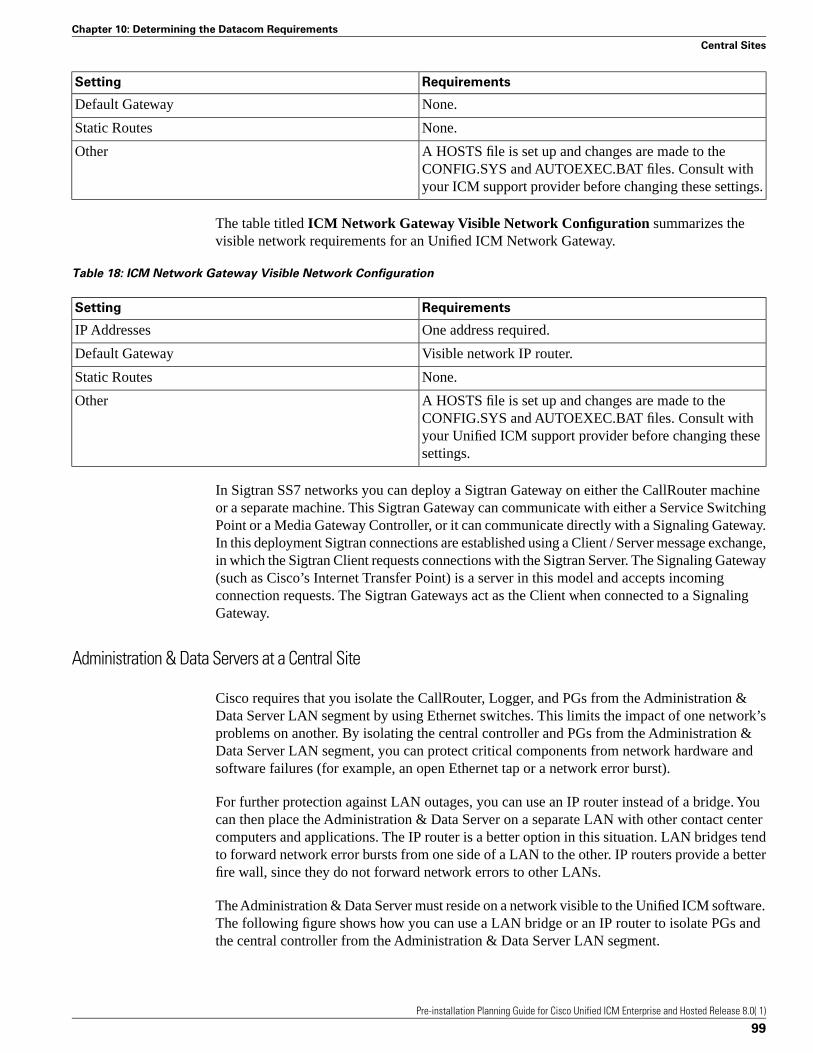
RequirementsSetting
None.Default Gateway
None.Static Routes
A HOSTS file is set up and changes are made to theCONFIG.SYS and AUTOEXEC.BAT files. Consult withyour ICM support provider before changing these settings.
Other
The table titled ICM Network Gateway Visible Network Configuration summarizes thevisible network requirements for an Unified ICM Network Gateway.
Table 18: ICM Network Gateway Visible Network Configuration
RequirementsSetting
One address required.IP Addresses
Visible network IP router.Default Gateway
None.Static Routes
A HOSTS file is set up and changes are made to theCONFIG.SYS and AUTOEXEC.BAT files. Consult with
Other
your Unified ICM support provider before changing thesesettings.
In Sigtran SS7 networks you can deploy a Sigtran Gateway on either the CallRouter machineor a separate machine. This Sigtran Gateway can communicate with either a Service SwitchingPoint or a Media Gateway Controller, or it can communicate directly with a Signaling Gateway.In this deployment Sigtran connections are established using a Client / Server message exchange,in which the Sigtran Client requests connections with the Sigtran Server. The Signaling Gateway(such as Cisco’s Internet Transfer Point) is a server in this model and accepts incomingconnection requests. The Sigtran Gateways act as the Client when connected to a SignalingGateway.
Administration & Data Servers at a Central Site
Cisco requires that you isolate the CallRouter, Logger, and PGs from the Administration &Data Server LAN segment by using Ethernet switches. This limits the impact of one network’sproblems on another. By isolating the central controller and PGs from the Administration &Data Server LAN segment, you can protect critical components from network hardware andsoftware failures (for example, an open Ethernet tap or a network error burst).
For further protection against LAN outages, you can use an IP router instead of a bridge. Youcan then place the Administration & Data Server on a separate LAN with other contact centercomputers and applications. The IP router is a better option in this situation. LAN bridges tendto forward network error bursts from one side of a LAN to the other. IP routers provide a betterfire wall, since they do not forward network errors to other LANs.
The Administration & Data Server must reside on a network visible to the Unified ICM software.The following figure shows how you can use a LAN bridge or an IP router to isolate PGs andthe central controller from the Administration & Data Server LAN segment.
Pre-installation Planning Guide for Cisco Unified ICM Enterprise and Hosted Release 8.0( 1)
99
Chapter 10: Determining the Datacom Requirements
Central Sites

Figure 38: Administration & Data Server at a Central Site
Peripheral Gateways at a Central Site
A Peripheral Gateway (PG) that is co-located with one or both sides of the central controllercan share the same visible LAN segment as the CallRouter and Logger nodes. The PG cancommunicate with the local CallRouter through the visible LAN. If the sides of the centralcontroller are geographically separated, the PG communicates with the other side through thevisible IP router and a WAN link. (If both sides of the central controller are co-located with thePG, then the PG communicates with both sides through the visible LAN.)
The following figure shows the network connection for a PG at a central site.
Figure 39: Peripheral Gateway at a Central Site
Pre-installation Planning Guide for Cisco Unified ICM Enterprise and Hosted Release 8.0( 1)
100
Chapter 10: Determining the Datacom Requirements
Central Sites

The ACD itself can also be on the visible LAN.
If the PG is duplexed, then the two duplexed PGs must be connected through a separate privatenetwork. (They cannot use the same private network as the CallRouter and Logger.) See thefollowing figure.
Figure 40: Duplexed Peripheral Gateways at a Central Site
If you have more than one pair of duplexed PGs at a site, each pair requires its own privateLAN. The private LAN for the PGs allows for synchronization and state transfer between thePGs. It is not used for any other purpose.
Note: When a Peripheral Gateway is located with one side of a geographically distributed centralcontroller, you must have a WAN link directly connecting the visible WAN IP routers at thetwo central sites. This ensures that there is adequate visible network connectivity between thesides of the central controller. For more information on PG networking requirements, see thenext section, “Contact Center Sites.”
Contact Center Sites
Each contact center site includes at least one ACD, at least one Peripheral Gateway (PG), andoptionally, one or more Administration & Data Servers. Contact centers may also have anInteractive Voice Response (IVR) unit. For fault-tolerance, the contact center site must includea duplexed pair of PGs.
A remote contact center complex is reached via the visible network, often with multiple accesspaths and through multiple IP routers. The contact center site must have at least one IP routeron the visible network for communication with the central controller. For maximumfault-tolerance, the site should have two IP routers, each connecting to one side of the centralcontroller.
Pre-installation Planning Guide for Cisco Unified ICM Enterprise and Hosted Release 8.0( 1)
101
Chapter 10: Determining the Datacom Requirements
Contact Center Sites

Note: For information on installing and configuring the Unified ICM Peripheral Gatewaysoftware, see the Installation Guide for Cisco Unified ICM/Contact Center Enterprise & Hosted.
Simplexed PG Site
The following figure shows one option for a contact center configuration with a simplexed PGand an Administration & Data Server. This site contains an ACD and an IVR system. The IVRPG software and the ACD PG software may be installed on the same server hardware platform.
Figure 41: Contact Center with Simplexed PG
As shown in the preceding figure, the PG and Administration & Data Server share a singleEthernet LAN and an IP router. The IP router uses prioritization and IP fragmentation to minimizequeuing delays for high-priority Unified ICM system traffic. Cisco requires that the PG, ACD,IVR, and IP router be separated from other devices by a bridge or IP router. This isolates thecritical Unified ICM components from outages that might be caused by other equipment andnetworks.
The contact center example shown in the preceding figure is a low fault tolerance configuration.It is only for non-fault tolerant sites (for example, for contact center sites with one PG oradministrator sites with Administration & Data Servers only). A simplexed PG configurationcan represent a single point of failure. Loss of the only PG would stop the flow of real-time datafrom the contact center to the CallRouter and prevent the use of post-routing and translationroutes. You can protect against possible failures by using duplexed PGs.
Duplexed PG Site
A duplexed PG configuration provides enhanced fault-tolerance.
Pre-installation Planning Guide for Cisco Unified ICM Enterprise and Hosted Release 8.0( 1)
102
Chapter 10: Determining the Datacom Requirements
Contact Center Sites
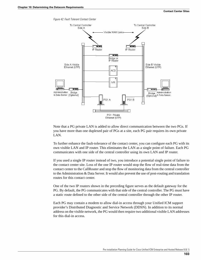
Figure 42: Fault Tolerant Contact Center
Note that a PG private LAN is added to allow direct communication between the two PGs. Ifyou have more than one duplexed pair of PGs at a site, each PG pair requires its own privateLAN.
To further enhance the fault-tolerance of the contact center, you can configure each PG with itsown visible LAN and IP router. This eliminates the LAN as a single point of failure. Each PGcommunicates with one side of the central controller using its own LAN and IP router.
If you used a single IP router instead of two, you introduce a potential single point of failure tothe contact center site. Loss of the one IP router would stop the flow of real-time data from thecontact center to the CallRouter and stop the flow of monitoring data from the central controllerto the Administration & Data Server. It would also prevent the use of post-routing and translationroutes for this contact center.
One of the two IP routers shown in the preceding figure serves as the default gateway for thePG. By default, the PG communicates with that side of the central controller. The PG must havea static route defined to the other side of the central controller through the other IP router.
Each PG may contain a modem to allow dial-in access through your Unified ICM supportprovider’s Distributed Diagnostic and Service Network (DDSN). In addition to its normaladdress on the visible network, the PG would then require two additional visible LAN addressesfor this dial-in access.
Pre-installation Planning Guide for Cisco Unified ICM Enterprise and Hosted Release 8.0( 1)
103
Chapter 10: Determining the Datacom Requirements
Contact Center Sites

Duplexed PG Site with Separate IVR LAN
Another contact center configuration may be used in cases where IVR systems need to beseparated due to security concerns or when management of the IVRs must be carefully protected.The following figure shows an example of such a fault tolerant contact center site.
Figure 43: Fault Tolerant Contact Center—IVR on Separate LAN
With this option, the ACD is on the visible LAN under the assumption that another CTIapplication needs to interface to the ACD. An alternative would be to have the ACD on thesame LAN as the IVR system.
PG Network Configuration
The table titled Simplexed PG Network Configuration summarizes the network configurationfor a simplexed PG.
Table 19: Simplexed PG Network Configuration
RequirementsSetting
Three addresses may be required on the visible LAN: onefor normal data and two for use by the DDSN.
IP Addresses
Define one of the visible network IP routers as the defaultgateway for the PG.
Default Gateway
Pre-installation Planning Guide for Cisco Unified ICM Enterprise and Hosted Release 8.0( 1)
104
Chapter 10: Determining the Datacom Requirements
Contact Center Sites

RequirementsSetting
Define one static route to the visible LAN at the central sitethat is not targeted by the default gateway IP router.
Static Routes
Preferred and alternate DNS server. See Active DirectoryModel (page 88).
Other
The table titled Duplexed PG Network Configuration summarizes the network configurationfor a duplexed PG.
Table 20: Duplexed PG Network Configuration
RequirementsSetting
Each PG may require three addresses on the visible LAN(one for normal traffic plus two addresses for DDSN dial-up
IP Addresses
connections) and two addresses on the private LAN (onefor high priority and one for low priority data).
Define one of the visible network IP routers as the defaultgateway for each PG. Do not use the same IP router as thedefault gateway for both PGs.
Default Gateway
Each PG requires a static route to the side of the centralcontroller that is not targeted by its default gateway IProuter.
Static Routes
Preferred and alternate DNS server. See Active DirectoryModel (page 88).
Other
Note: For more information on how Peripheral Gateways connect to ACDs, see Chapter 5,“Peripheral Gateway Configurations” (page 33).
Contact Center IP Routers
The IP router requires a single address on the LAN. It also requires that you define a static routeon the IP router to the side of the central controller (central site visible LAN) that is not targetedby the PG’s default gateway IP router.
To allow optimal tuning of the network, Cisco requires that you use IP routers that allow youto prioritize packets based on a range of source or destination port numbers. Typically, you needto set up the IP router to give higher priority to certain outgoing network packets. Also, dependingon the bandwidth available on the visible WAN, you may need to set up IP fragmentation.
The table titled Contact Center IP Router Configurationsummarizes the configuration forthe IP routers.
Table 21: Contact Center IP Router Configuration
RequirementsSetting
Each IP router requires one address on the visible LAN.IP Addresses
Network bridge or IP router used as bridge, if any.Otherwise, the IP router does not have a default gateway.
Default Gateway
Pre-installation Planning Guide for Cisco Unified ICM Enterprise and Hosted Release 8.0( 1)
105
Chapter 10: Determining the Datacom Requirements
Contact Center Sites

RequirementsSetting
Each IP router must have a static route to reach one centralsite visible LAN.
Static Routes
Turn off any preset routing protocols. Give higher priorityto specific network packets. Use fragmentation if necessaryto limit the queuing delay.
Other
Note: See the following table for information about packet priorities.
Table 22: Contact Center Packet Priorities
Low PriorityHigh PriorityPacket Type
If sending to any other address.If sending to the CallRouter’s highpriority address (as derived from thepacket’s destination address).
TCP
All other UDP packets.If source or destination port number isin the range 39000–39999.
UDP
The maximum queuing delay is 50 milliseconds if the site uses post-routing or translation routes;200 milliseconds otherwise. You may have to set up fragmentation to meet these limits.
Admin Sites
An administrator site contains one or more Administration & Data Servers. Each administratorsite must have a visible LAN and an IP router to communicate with the central sites. Anadministrator site does not require a private LAN.
Pre-installation Planning Guide for Cisco Unified ICM Enterprise and Hosted Release 8.0( 1)
106
Chapter 10: Determining the Datacom Requirements
Contact Center Sites

Figure 44: Admin Site Configuration
You can have multiple Administration & Data Servers on a single LAN.
Pre-installation Planning Guide for Cisco Unified ICM Enterprise and Hosted Release 8.0( 1)
107
Chapter 10: Determining the Datacom Requirements
Contact Center Sites

Pre-installation Planning Guide for Cisco Unified ICM Enterprise and Hosted Release 8.0( 1)
108
Chapter 10: Determining the Datacom Requirements
Contact Center Sites

Site PreparationOnce you have provisioned IXC access, ordered the required ACD/PBX options, ordered theserver platform, and determined your data communications requirements, you can begin preparingfor the arrival of the Unified ICM equipment. You need to prepare each site that is to containUnified ICM equipment. The sites must have adequate power facilities, security, and space forequipment layout.
Be sure to consider the following site preparation tasks:
• Meet basic site requirements. Prepare for the arrival of equipment; provide a secure stagingarea; ensure that sites are ready for occupancy; order and assemble equipment racks.
• Design a floor plan for each site. Consider operator workspace, cabling distribution, andmaintenance access to Unified ICM nodes.
• Meet the power and environmental requirements at each site. Review the server hardwaredocumentation for specifics on power and environmental requirements.
• Provide adequate security for the Unified ICM system. Allow only authorized access to theUnified ICM system and any backed-up data.
• Determine additional cabling or other equipment required. You may need equipment suchas rack-mounting hardware or an uninterruptible power supply (UPS).
• Order any additional cabling or equipment. Order any additional equipment in time for thearrival of the Unified ICM system components.
Pre-installation Planning Guide for Cisco Unified ICM Enterprise and Hosted Release 8.0( 1)
109
Chapter 11

Pre-installation Planning Guide for Cisco Unified ICM Enterprise and Hosted Release 8.0( 1)
110
Chapter 11: Site Preparation

IP Address WorksheetsThis chapter provides worksheets you can use to record IP addresses for the visible and privatenetworks. You also need to define static routes for some of the nodes in the Unified ICM system.
This chapter contains the following topics:
• Visible Network IP Address Requirements, page 111• Private Network IP Address Requirements, page 113• Signaling Access Network IP Requirements, page 115• Static Route Requirements, page 116
Visible Network IP Address Requirements
The table titled Visible Network IP Address Requirements lists the IP address requirementsfor Unified ICM node connections to the visible network. The Unified ICM nodes are listed asduplexed pairs (for example, CallRouter A and CallRouter B). You may or may not haveduplexed nodes in your configuration. Supply IP addresses only for the nodes you have in yourconfiguration.
Table 23: Visible Network IP Address Requirements
IP AddressAddress TypeLocationNode
High PriorityCallRouter A
Low Priority
Default IP Gateway
Netmask
High PriorityCallRouter B
Low Priority
Default IP Gateway
Pre-installation Planning Guide for Cisco Unified ICM Enterprise and Hosted Release 8.0( 1)
111
Chapter 12

IP AddressAddress TypeLocationNode
Netmask
Normal DataLogger A
RAS 1
RAS 2
Default IP Gateway1
Netmask
Modem Tel. Number
Normal DataLogger B
RAS 1
RAS 2
Default IP Gateway1
Netmask
Modem Tel. Number
Normal dataCentral Site IP Router
Normal dataRemote Contact Center SiteIP Route
Normal DataPG1A
RAS 1
RAS 2
Default IP Gateway1
Netmask
Modem Tel. Number
Normal DataPG1B
RAS 1
RAS 2
Default IP Gateway1
Netmask
Modem Tel. Number
Normal DataPG2A
RAS 1
RAS 2
Default IP Gateway1
Netmask
Modem Tel. Number
Normal DataPG2B
Pre-installation Planning Guide for Cisco Unified ICM Enterprise and Hosted Release 8.0( 1)
112
Chapter 12: IP Address Worksheets
Visible Network IP Address Requirements

IP AddressAddress TypeLocationNode
RAS 1
RAS 2
Default IP Gateway1
Netmask
Modem Tel. Number
Normal DataPG3A
RAS 1
RAS 2
Default IP Gateway1
Netmask
Modem Tel. Number
Normal DataPG3B
RAS 1
RAS 2
Default IP Gateway1
Netmask
Modem Tel. Number
Normal DataAW1
Default IP Gateway1
Netmask
Normal DataAW2
Default IP Gateway1
Netmask
Private Network IP Address Requirements
The table titled Private Network IP Address Requirements lists the IP address requirementsfor Unified ICM node connections to the private network. The Unified ICM nodes are listed asduplexed pairs (for example, CallRouter A and CallRouter B). You may or may not haveduplexed nodes in your configuration. You need to supply IP addresses only for the nodes youhave in your configuration.
Table 24: Private Network IP Address Requirements (continued)
IP AddressAddres TypeLocationNode
High PriorityCallRouter A
Low Priority
Pre-installation Planning Guide for Cisco Unified ICM Enterprise and Hosted Release 8.0( 1)
113
Chapter 12: IP Address Worksheets
Private Network IP Address Requirements

IP AddressAddres TypeLocationNode
Default IP Gateway
Netmask
High PriorityCallRouter B
Low Priority
Default IP Gateway
Netmask
Normal DataLogger A
RAS 1
RAS 2
Default IP Gateway1
Netmask
Modem Tel. Number
Normal DataLogger B
RAS 1
RAS 2
Default IP Gateway1
Netmask
Modem Tel. Number
Normal DataCentral Site IP Router
Normal DataRemote Contact Center SiteIP Router
Normal DataPG1A
RAS 1
RAS 2
Default IP Gateway1
Netmask
Modem Tel. Number
Normal DataPG1B
RAS 1
RAS 2
Default IP Gateway1
Netmask
Modem Tel. Number
Normal DataPG2A
RAS 1
Pre-installation Planning Guide for Cisco Unified ICM Enterprise and Hosted Release 8.0( 1)
114
Chapter 12: IP Address Worksheets
Private Network IP Address Requirements
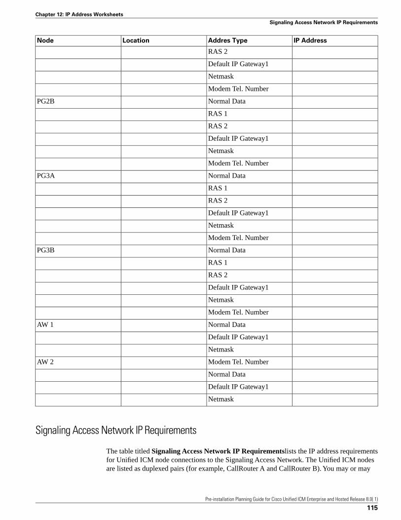
IP AddressAddres TypeLocationNode
RAS 2
Default IP Gateway1
Netmask
Modem Tel. Number
Normal DataPG2B
RAS 1
RAS 2
Default IP Gateway1
Netmask
Modem Tel. Number
Normal DataPG3A
RAS 1
RAS 2
Default IP Gateway1
Netmask
Modem Tel. Number
Normal DataPG3B
RAS 1
RAS 2
Default IP Gateway1
Netmask
Modem Tel. Number
Normal DataAW 1
Default IP Gateway1
Netmask
Modem Tel. NumberAW 2
Normal Data
Default IP Gateway1
Netmask
Signaling Access Network IP Requirements
The table titled Signaling Access Network IP Requirementslists the IP address requirementsfor Unified ICM node connections to the Signaling Access Network. The Unified ICM nodesare listed as duplexed pairs (for example, CallRouter A and CallRouter B). You may or may
Pre-installation Planning Guide for Cisco Unified ICM Enterprise and Hosted Release 8.0( 1)
115
Chapter 12: IP Address Worksheets
Signaling Access Network IP Requirements
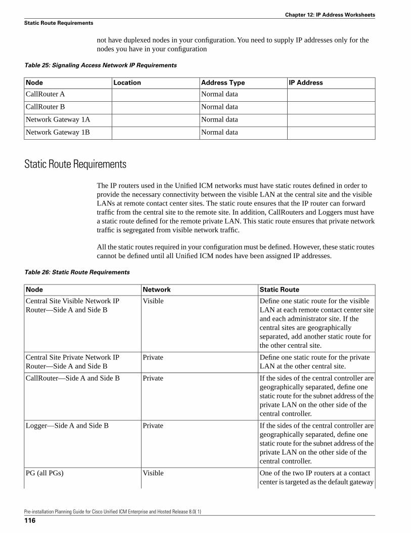
not have duplexed nodes in your configuration. You need to supply IP addresses only for thenodes you have in your configuration
Table 25: Signaling Access Network IP Requirements
IP AddressAddress TypeLocationNode
Normal dataCallRouter A
Normal dataCallRouter B
Normal dataNetwork Gateway 1A
Normal dataNetwork Gateway 1B
Static Route Requirements
The IP routers used in the Unified ICM networks must have static routes defined in order toprovide the necessary connectivity between the visible LAN at the central site and the visibleLANs at remote contact center sites. The static route ensures that the IP router can forwardtraffic from the central site to the remote site. In addition, CallRouters and Loggers must havea static route defined for the remote private LAN. This static route ensures that private networktraffic is segregated from visible network traffic.
All the static routes required in your configuration must be defined. However, these static routescannot be defined until all Unified ICM nodes have been assigned IP addresses.
Table 26: Static Route Requirements
Static RouteNetworkNode
Define one static route for the visibleLAN at each remote contact center site
VisibleCentral Site Visible Network IPRouter—Side A and Side B
and each administrator site. If thecentral sites are geographicallyseparated, add another static route forthe other central site.
Define one static route for the privateLAN at the other central site.
PrivateCentral Site Private Network IPRouter—Side A and Side B
If the sides of the central controller aregeographically separated, define one
PrivateCallRouter—Side A and Side B
static route for the subnet address of theprivate LAN on the other side of thecentral controller.
If the sides of the central controller aregeographically separated, define one
PrivateLogger—Side A and Side B
static route for the subnet address of theprivate LAN on the other side of thecentral controller.
One of the two IP routers at a contactcenter is targeted as the default gateway
VisiblePG (all PGs)
Pre-installation Planning Guide for Cisco Unified ICM Enterprise and Hosted Release 8.0( 1)
116
Chapter 12: IP Address Worksheets
Static Route Requirements

Static RouteNetworkNode
for the PG. However, the PG needs IPconnectivity to both sides of the centralcontroller. Therefore, for each PG youmust define a static route to the otherIP router (that is, to the IP router that isnot targeted as the PG’s default gatewayIP router).
For each IP router, define a static routeto one side of the central controller (to
VisibleRemote Contact Center IP Routers
the central site visible network IProuter).
For each Admin Site IP router, definea static route to one side of the central
VisibleAdmin Site IP Routers
controller (to the central site visiblenetwork IP router).
Pre-installation Planning Guide for Cisco Unified ICM Enterprise and Hosted Release 8.0( 1)
117
Chapter 12: IP Address Worksheets
Static Route Requirements

Pre-installation Planning Guide for Cisco Unified ICM Enterprise and Hosted Release 8.0( 1)
118
Chapter 12: IP Address Worksheets
Static Route Requirements
Index
802.1p marking ....86
Addresses
CallRouter....74, 76
CallRouter, ....94
IP router ....90, 91
Logger....95, 100
Peripheral Gateway ....101
Admin site
networking....67
Admin Workstation....69
agent workstation application ....44
CallRouter....95
configurations....92
IP router
IP router ....99
Packet Scheduler ....83
Performance Monitor....87
Peripheral Gateway....90
processor....68
Signaling network....92
Sites
central....38
TCP packets....92
UDP ....91
UDP packets ....91
Unshielded Twisted Pair....78
Visible network....79
central sites ....89
WAN....73
admin site....75
visible....75
Pre-installation Planning Guide for Cisco Unified ICM Enterprise and Hosted Release 8.0( 1)
Index 119
Index