Stochastic pre-event preparation for enhancing resilience ...
Pre-Installation and Site Preparation Guide
Loring S35 Kestrel Coffee RoasterTM
S35 Pre-Installation and Site Preparation Guide
Page 2 Document No. 1006705 Rev A
NoticesDocument Versioning Information
This manual, along with other manuals in this series, is intended to be a guideline for the installation and use for the product lines manufactured by Loring Smart Roast, Inc. The customer is responsible for complying with all applicable regulations.
The customer should refer to a licensed professional contractor or contractors for all installation details.
© Loring Smart Roast, Inc. All rights reserved.
The name LORING SMART ROAST, the Loring logo, and the catchphrase “The Smarter Way To Roast” are all trademarks of Loring Smart Roast, Inc.
Warranty is void unless product is installed and used in accordance with all written instructions.
Throughout this manual, the following signal words are used to identify the degree of seriousness in any operation that presents a potentially hazardous situation.
Dangers, Warnings, and Cautions
Document No. 1006705 Rev A
Date Last Exported: March 2, 2017
DANGER: Indicates a hazard that WILL cause severe personal injury, death, or substantial property damage if ignored.
WARNING: Indicates a hazard that could cause SEVERE personal injury, death, or substantial property damage if ignored.
CAUTION: Indicates a hazard that could cause MINOR personal injury or property damage if ignored.

S35 Pre-Installation and Site Preparation Guide
Document No. 1006705 Rev A Page 3
Follow all written instructions provided by Loring, and verbal instructions from Loring Customer Support, regarding site preparation prior to receiving the coffee roasting equipment.
All contractors or subcontractors involved in installation or working with specific connections (e.g., water, air, gas, electrical, hot and cold exhaust ventilation) should be fully licensed and qualified in that particular functional area.
Comply with all applicable rules and regulations and governing agencies.
Loring reserves the right to change information within this document at any time without notice.
Pre-Installation and Site Preparation Guide General Notes
S35 Pre-Installation and Site Preparation Guide
Page 4 Document No. 1006705 Rev A
ContentsIntroduction _________________________________________________ 6
Audience _______________________________________________ 6Acquiring a Coffee Roaster _________________________________ 6
S35 Specifications ____________________________________________ 9Requirements for Utilities ___________________________________10Power Specification _______________________________________11
Dimensions and Clearances ____________________________________13Overall Footprint __________________________________________13Footprint – S35 Roaster and Cart ____________________________14Floor Clearances – S35 Roaster and Cart ______________________15Floor Clearances – S35 with D35 Destoner _____________________16Overhead Clearances – S35 Roaster _________________________17Footprint - S35 Roaster Feet ________________________________1845-Degree Vent Kit ________________________________________19
Space Planning ______________________________________________21Indoors _________________________________________________21Floor ___________________________________________________21Destoner Position _________________________________________22Stack Connection Location _________________________________24Door Openings ___________________________________________25Local Codes _____________________________________________26Utilities _________________________________________________26Room Size and Ventilation __________________________________26Low Ceiling ______________________________________________27Multi-Story Buildings_______________________________________27Workflow Space __________________________________________28

S35 Pre-Installation and Site Preparation Guide
Document No. 1006705 Rev A Page 5
Lighting _________________________________________________30Network ________________________________________________30
Receiving Shipment __________________________________________31Shipping Notes ___________________________________________31S35 Shipping Configuration _________________________________32Lifting and Moving the Roaster_______________________________35
Next Steps __________________________________________________38Site Preparation Checklist __________________________________38
Manufacturer Contact Information _______________________________39
S35 Pre-Installation and Site Preparation Guide
Page 6 Document No. 1006705 Rev A
IntroductionAudience
Acquiring a Coffee Roaster
The intended audience for this manual, the S35 Pre-Installation and Site Preparation Guide, includes customer-side administrators, floor employees, general contractors, facilities managers and other individuals who are responsible for preparing the site for installation of the roaster.
Preparing for and installing a Loring coffee roaster requires cooperation between the customer and Loring over several weeks. Generally, the customer should begin preparing the site 3 months prior to shipping. Upon receiving the roaster, the customer’s general contractor assembles the roaster, connects the utilities including water, gas, and electric, connects the hot and cold exhaust ventilation, and then waits for the Loring Field Service Technician to perform final system commissioning. The commissioning period also includes hands-on customer training in the use and maintenance of the roaster.
Some tasks, such as ordering stack ventilation components, may require specifying and purchasing equipment from third-party suppliers. Allow sufficient lead times.
WARNING: Operating the roaster prior to final inspection and commissioning by an authorized Loring Field Service Technician will void the warranty.
S35 Pre-Installation and Site Preparation Guide
Document No. 1006705 Rev A Page 7
Additional Documentation
The following additional documentation is available to aid with installation and setup. Contact your Loring Account Representative for more information.
• Welcome Packet. The Welcome Packet contains detailed instructions and information sent by Loring to each new customer upon purchase of a coffee roaster. One item, the Product Specification Form, must be completed and returned to Loring in order for Loring to begin building the roaster.
• Product Specification Form (PSF). The customer must provide information to Loring regarding the site’s utility characteristics. This information is used to configure the roaster at the factory, a process that requires several weeks’ lead time. Loring strongly recommends working with a licensed professional contractor when providing this information. This form is included in the Welcome Packet.
• Suggested Stack Manufacturers. One of the items in the Welcome Packet is a list of recommended manufacturers of stack ventilation components. Loring recommends ordering stacks 6 weeks prior to the arrival of the roaster.
• Installation and Assembly Guide. After receiving the coffee roaster, the customer must engage with a licensed general contractor to assemble, position, and hook up the roaster to various utilities and stack ventilation.
• Mechanical Interface Control Documents (MICDs). These technical drawings provide detailed information on system dimensioning and components, as well as system weights. They are intended for permit submittals and for use by general contractors, as well as by architects and facilities planners. These drawings are available upon request from Loring.
• Special Reports for Permitting. Additional reports on various technical subjects are available from Loring. Each customer may need to satisfy unique local or regional regulatory requirements. For example, air quality reports are typically required, and some locations may require both county and city permits.
The Product Specification Form (PSF) conveys extremely important customer information regarding the customer site’s power supply voltage and network configuration. Loring requires this form to be completed by the customer a minimum of 9 weeks prior to production completion. Any delay in providing any portion of this information can delay the roaster production by a corresponding number of weeks.

S35 Pre-Installation and Site Preparation Guide
Page 8 Document No. 1006705 Rev A
Equipment
The core pieces of Loring coffee-roasting equipment are as follows:
• S35 coffee roaster• C35 Green Bean Cart (included with S35 roaster)• D35 Destoner (optional)
S35 Coffee Roaster
C35 Green Bean Cart
D35 Destoner
S35 Pre-Installation and Site Preparation Guide
Document No. 1006705 Rev A Page 9
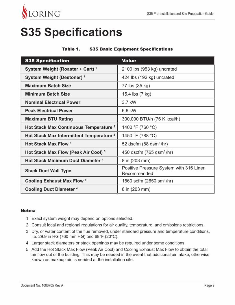
S35 Specifications
S35 Specification Value
System Weight (Roaster + Cart) 1 2100 lbs (953 kg) uncrated
System Weight (Destoner) 1 424 lbs (192 kg) uncrated
Maximum Batch Size 77 lbs (35 kg)
Minimum Batch Size 15.4 lbs (7 kg)
Nominal Electrical Power 3.7 kW
Peak Electrical Power 6.6 kW
Maximum BTU Rating 300,000 BTU/h (76 K kcal/h)
Hot Stack Max Continuous Temperature 2 1400 °F (760 °C)
Hot Stack Max Intermittent Temperature 2 1450 °F (788 °C)
Hot Stack Max Flow 3 52 dscfm (88 dsm3 /hr)
Hot Stack Max Flow (Peak Air Cool) 5 450 dscfm (765 dsm3 /hr)
Hot Stack Minimum Duct Diameter 4 8 in (203 mm)
Stack Duct Wall Type Positive Pressure System with 316 Liner Recommended
Cooling Exhaust Max Flow 5 1560 scfm (2650 sm3 /hr)
Cooling Duct Diameter 4 8 in (203 mm)
Table 1. S35 Basic Equipment Specifications
Notes:
1 Exact system weight may depend on options selected.2 Consult local and regional regulations for air quality, temperature, and emissions restrictions.3 Dry, or water content of the flue removed, under standard pressure and temperature conditions,
i.e. 29.9 in HG (760 mm HG) and 68°F (20°C). 4 Larger stack diameters or stack openings may be required under some conditions.5 Add the Hot Stack Max Flow (Peak Air Cool) and Cooling Exhaust Max Flow to obtain the total
air flow out of the building. This may be needed in the event that additional air intake, otherwise known as makeup air, is needed at the installation site.
S35 Pre-Installation and Site Preparation Guide
Page 10 Document No. 1006705 Rev A
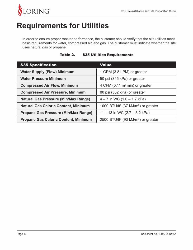
S35 Specification Value
Water Supply (Flow) Minimum 1 GPM (3.8 LPM) or greater
Water Pressure Minimum 50 psi (345 kPa) or greater
Compressed Air Flow, Minimum 4 CFM (0.11 m3 min) or greater
Compressed Air Pressure, Minimum 80 psi (552 kPa) or greater
Natural Gas Pressure (Min/Max Range) 4 – 7 in WC (1.0 – 1.7 kPa)
Natural Gas Caloric Content, Minimum 1000 BTU/ft3 (37 MJ/m3) or greater
Propane Gas Pressure (Min/Max Range) 11 – 13 in WC (2.7 – 3.2 kPa)
Propane Gas Caloric Content, Minimum 2500 BTU/ft3 (93 MJ/m3) or greater
Requirements for UtilitiesIn order to ensure proper roaster performance, the customer should verify that the site utilities meet basic requirements for water, compressed air, and gas. The customer must indicate whether the site uses natural gas or propane.
Table 2. S35 Utilities Requirements
S35 Pre-Installation and Site Preparation Guide
Document No. 1006705 Rev A Page 11
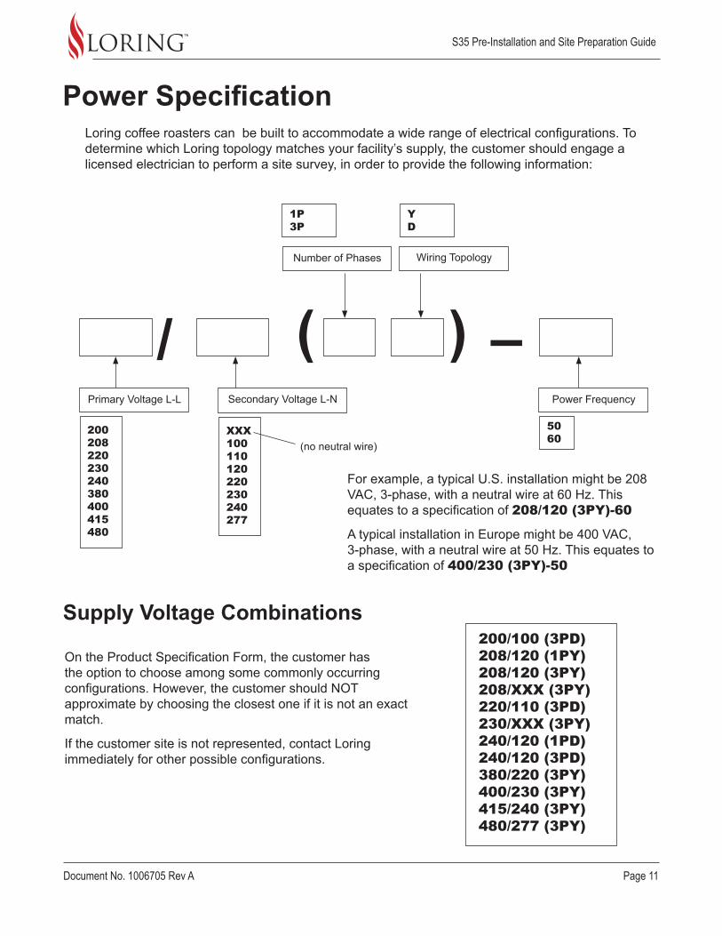
Power SpecificationLoring coffee roasters can be built to accommodate a wide range of electrical configurations. To determine which Loring topology matches your facility’s supply, the customer should engage a licensed electrician to perform a site survey, in order to provide the following information:
On the Product Specification Form, the customer has the option to choose among some commonly occurring configurations. However, the customer should NOT approximate by choosing the closest one if it is not an exact match.
If the customer site is not represented, contact Loring immediately for other possible configurations.
For example, a typical U.S. installation might be 208 VAC, 3-phase, with a neutral wire at 60 Hz. This equates to a specification of 208/120 (3PY)-60
A typical installation in Europe might be 400 VAC, 3-phase, with a neutral wire at 50 Hz. This equates to a specification of 400/230 (3PY)-50
(/ –
Supply Voltage Combinations
)Primary Voltage L-L Power Frequency
50 60
1P 3P
Y D
200 208 220 230 240 380 400 415 480
200/100 (3PD) 208/120 (1PY) 208/120 (3PY) 208/XXX (3PY) 220/110 (3PD) 230/XXX (3PY) 240/120 (1PD) 240/120 (3PD) 380/220 (3PY) 400/230 (3PY) 415/240 (3PY) 480/277 (3PY)
XXX 100 110 120 220 230 240 277
Wiring TopologyNumber of Phases
Secondary Voltage L-N
(no neutral wire)

S35 Pre-Installation and Site Preparation Guide
Page 12 Document No. 1006705 Rev A
The information under Power Specification is as follows:
• Voltage: Designates the type of power voltage at the site.
» The L-L number is the Primary or Line-to-Line voltage.
» The L-N is the Secondary Line-to-Neutral voltage, which may be represented as “XXX” if the site does not have a neutral wire.
• Number of Phases: The Number of Phases represents the number of Line-to-Line phases. This is either 1P or 3P, indicating single phase or three phase respectively.
• Wiring Topology: The type of circuit. Refer to Loring Engineering Document No. 1001163 for more information.
» Y= Wye
» D= Delta
• Power Frequency: The last informational block designates the site’s voltage frequency, in Hertz (Hz).
In order for the roaster to function properly, the customer is responsible for installing service to the required level of amperage as follows:
• 200 VAC – 240 VAC:
» 1P – 40 Amps
» 3P – 30 Amps
• 380 VAC – 480 VAC – 20 Amps
Supply Voltages, Explained
Supply Amperage
3-Phase Wye 3-Phase Delta
S35 Pre-Installation and Site Preparation Guide
Document No. 1006705 Rev A Page 13
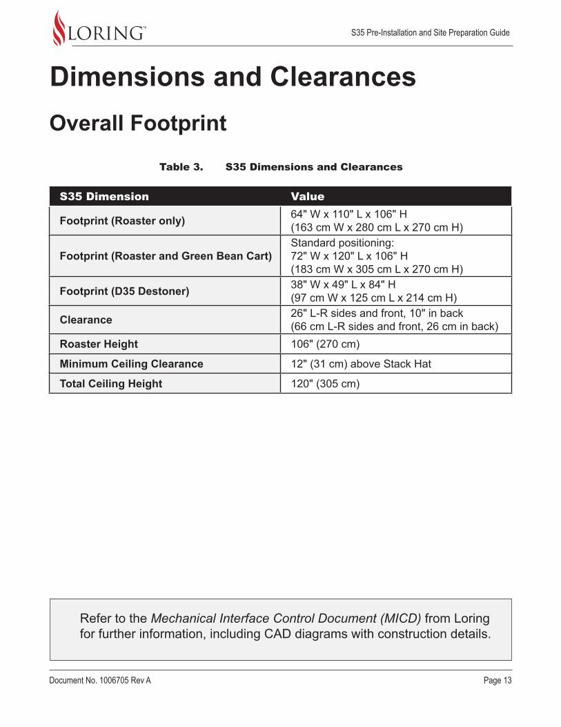
Dimensions and ClearancesOverall Footprint
Refer to the Mechanical Interface Control Document (MICD) from Loring for further information, including CAD diagrams with construction details.
S35 Dimension Value
Footprint (Roaster only) 64" W x 110" L x 106" H(163 cm W x 280 cm L x 270 cm H)
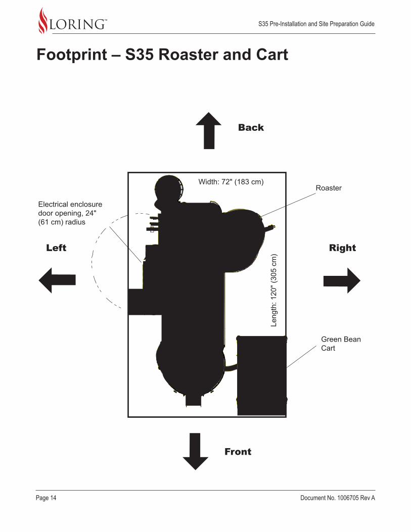
Footprint (Roaster and Green Bean Cart)Standard positioning:72" W x 120" L x 106" H(183 cm W x 305 cm L x 270 cm H)
Footprint (D35 Destoner) 38" W x 49" L x 84" H(97 cm W x 125 cm L x 214 cm H)
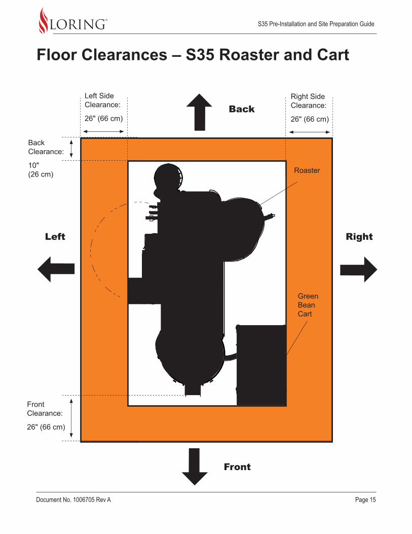
Clearance 26" L-R sides and front, 10" in back(66 cm L-R sides and front, 26 cm in back)
Roaster Height 106" (270 cm)
Minimum Ceiling Clearance 12" (31 cm) above Stack Hat
Total Ceiling Height 120" (305 cm)
Table 3. S35 Dimensions and Clearances
S35 Pre-Installation and Site Preparation Guide
Page 14 Document No. 1006705 Rev A
Front
Left Right
Back
Footprint – S35 Roaster and Cart
Roaster
Leng
th: 1
20" (
305
cm)
Width: 72" (183 cm)
Electrical enclosure door opening, 24" (61 cm) radius
Green Bean Cart
S35 Pre-Installation and Site Preparation Guide
Document No. 1006705 Rev A Page 15
Front
Left Right
Back
Floor Clearances – S35 Roaster and Cart
Roaster
Left Side Clearance:
26" (66 cm)
Right Side Clearance:
26" (66 cm)
Back Clearance:
10" (26 cm)
Front Clearance:
26" (66 cm)
Green Bean Cart
S35 Pre-Installation and Site Preparation Guide
Page 16 Document No. 1006705 Rev A
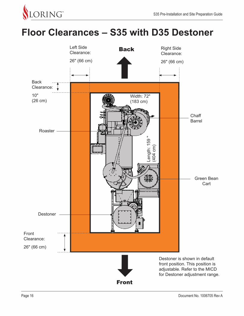
Destoner is shown in default front position. This position is adjustable. Refer to the MICD for Destoner adjustment range.
Front
Back
Chaff Barrel
Green Bean Cart
Destoner
Roaster
Floor Clearances – S35 with D35 Destoner
Leng
th: 1
59 "
(404
cm
)
Back Clearance:
10" (26 cm)
Left Side Clearance:
26" (66 cm)
Right Side Clearance:
26" (66 cm)
Width: 72" (183 cm)
Front Clearance:
26" (66 cm)

S35 Pre-Installation and Site Preparation Guide
Document No. 1006705 Rev A Page 17
Overhead Clearances – S35 Roaster
Overhead clearance should accommodate the roaster plus a minimum stack height. This clearance is also necessary for routine maintenance, as well as providing room to maneuver during installation.
Minimum Total Ceiling Height: 118" (300 cm)
Clearance:
12" (31 cm)
Height:
106" (270 cm)
S35 Pre-Installation and Site Preparation Guide
Page 18 Document No. 1006705 Rev A
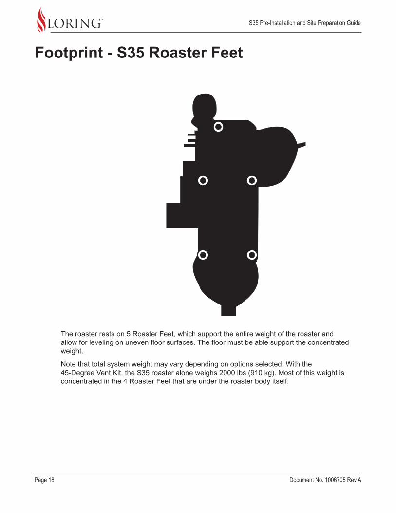
Footprint - S35 Roaster Feet
The roaster rests on 5 Roaster Feet, which support the entire weight of the roaster and allow for leveling on uneven floor surfaces. The floor must be able support the concentrated weight.
Note that total system weight may vary depending on options selected. With the 45-Degree Vent Kit, the S35 roaster alone weighs 2000 lbs (910 kg). Most of this weight is concentrated in the 4 Roaster Feet that are under the roaster body itself.

S35 Pre-Installation and Site Preparation Guide
Document No. 1006705 Rev A Page 19
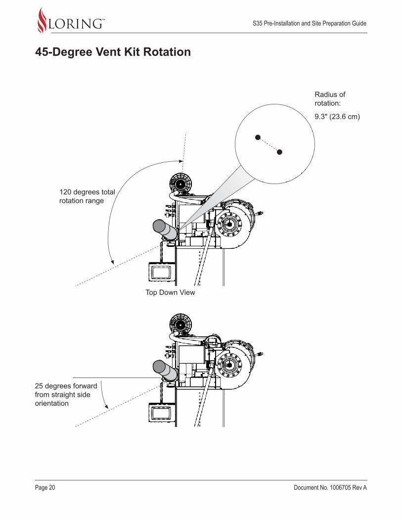
45-Degree Vent Kit
The 45-Degree Vent Kit is an optional 2-piece component set for the Cooling Exhaust Vent that acts as an extender. It provides additional range for positioning the exit point, including rotating around the roaster attachment point, and can be removed to facilitate cleaning of the Cooling Vent.
This kit is a special order item. If needed, it is shipped with the roaster in the Accessory crate.
Front
Back
24" (61 cm)
S35 Pre-Installation and Site Preparation Guide
Page 20 Document No. 1006705 Rev A
45-Degree Vent Kit Rotation
25 degrees forward from straight side orientation
120 degrees total rotation range
Top Down View
Radius of rotation:
9.3" (23.6 cm)
S35 Pre-Installation and Site Preparation Guide
Document No. 1006705 Rev A Page 21
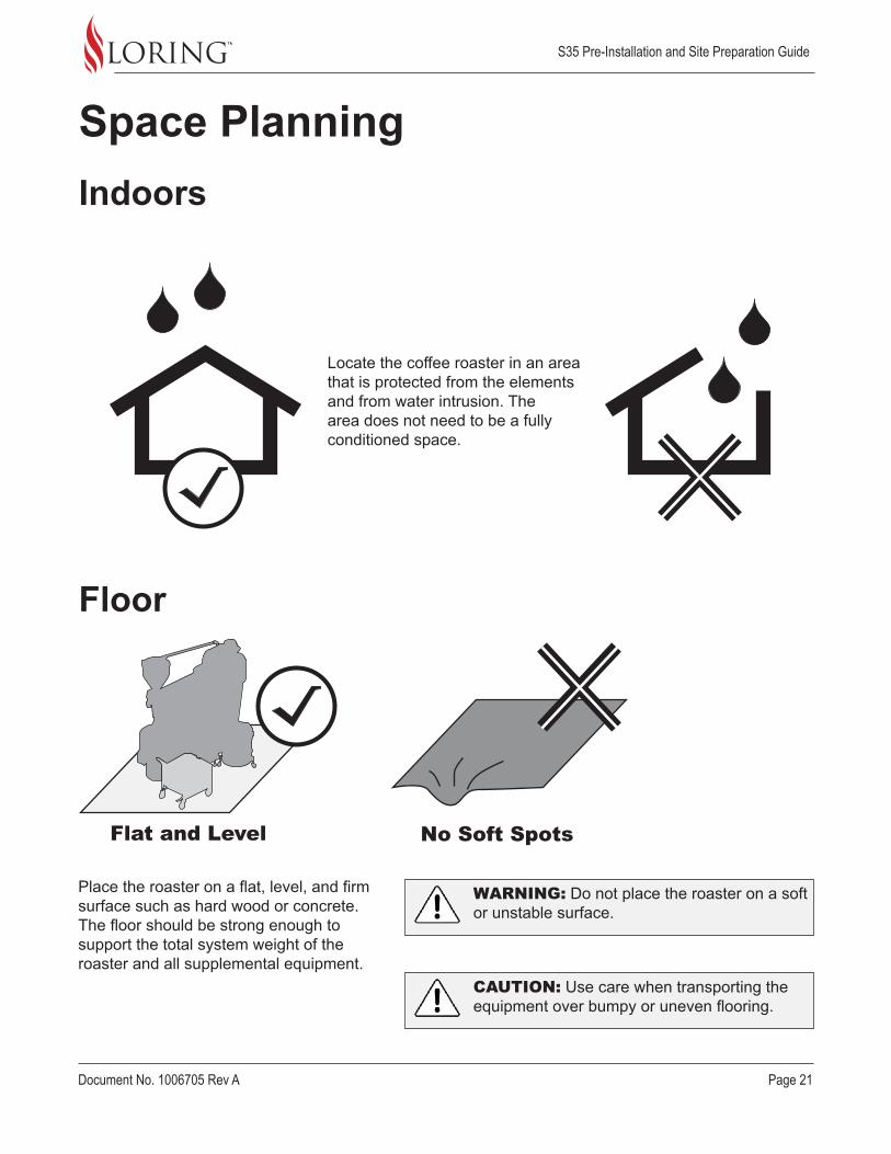
Indoors
Floor
Flat and Level No Soft Spots
Space Planning
Locate the coffee roaster in an area that is protected from the elements and from water intrusion. The area does not need to be a fully conditioned space.
Place the roaster on a flat, level, and firm surface such as hard wood or concrete. The floor should be strong enough to support the total system weight of the roaster and all supplemental equipment.
CAUTION: Use care when transporting the equipment over bumpy or uneven flooring.
WARNING: Do not place the roaster on a soft or unstable surface.

S35 Pre-Installation and Site Preparation Guide
Page 22 Document No. 1006705 Rev A
Destoner PositionThe Destoner is an optional piece of equipment for removing stones and debris from freshly roasted beans. It is positioned up against the Cooling Tray.
The Destoner cannot be easily moved, once placed. The Green Bean Cart is on wheels, and is more easily moved.
Front
Back
Roaster
Cooling Tray
Chaff Barrel
Green Bean Cart
Destoner
The operator can rotate the Cooling Tray in place as needed.
The default position of the Destoner in front of the roaster.
S35 Pre-Installation and Site Preparation Guide
Document No. 1006705 Rev A Page 23
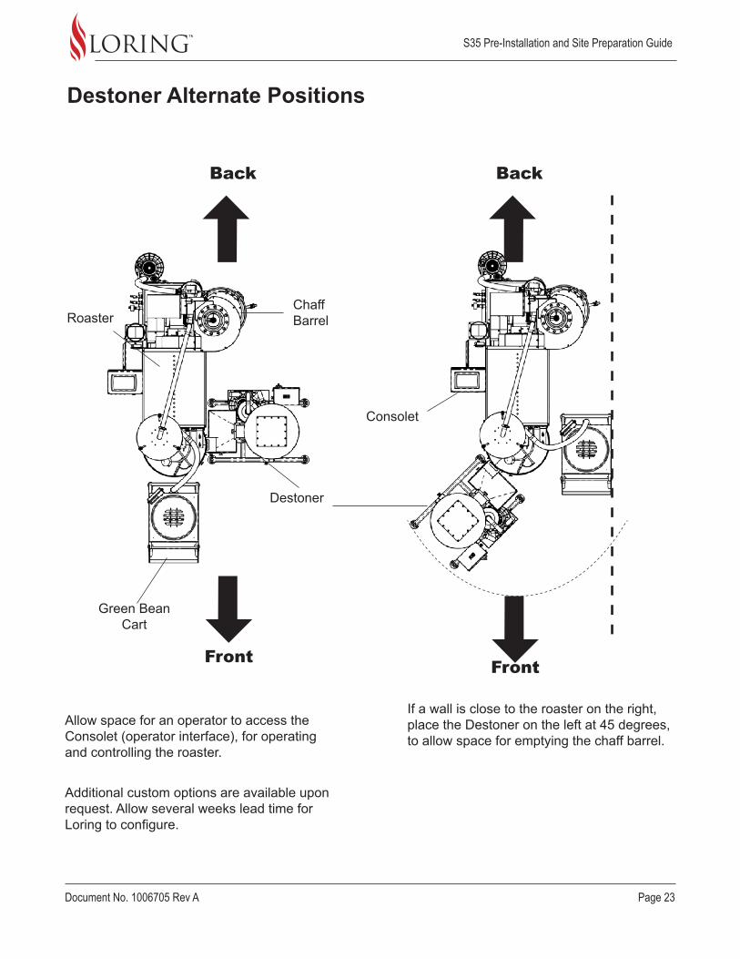
Destoner Alternate Positions
If a wall is close to the roaster on the right, place the Destoner on the left at 45 degrees, to allow space for emptying the chaff barrel.
Allow space for an operator to access the Consolet (operator interface), for operating and controlling the roaster.
Additional custom options are available upon request. Allow several weeks lead time for Loring to configure.
Front Front
Back Back
Chaff Barrel
Consolet
Green Bean Cart
Destoner
Roaster

S35 Pre-Installation and Site Preparation Guide
Page 24 Document No. 1006705 Rev A
Stack Connection LocationThe ventilation stacks connect to openings in the wall or roof. An optimal location is directly above the corresponding stack connections on the roaster.
Refer to the Mechanical Interface Control Documents from Loring for:
• Exact dimensions and locations on the roaster.• Stack elbow options for routing through existing openings.
Check local building codes for additional stack ventilation requirements.
Assistance with stack design is available through Loring upon request. Loring recommends engaging with a stack design consultant to create details for complex site configurations.
Cooling Vent
Stack (hot air)
S35 Pre-Installation and Site Preparation Guide
Document No. 1006705 Rev A Page 25
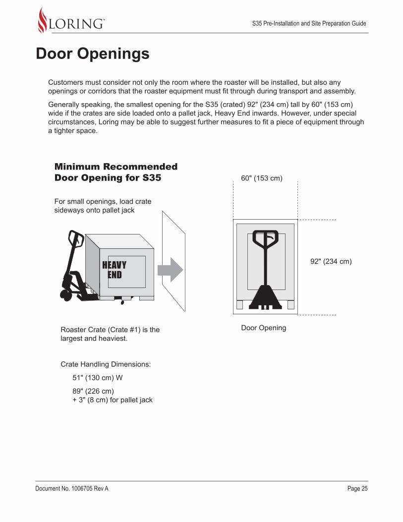
Customers must consider not only the room where the roaster will be installed, but also any openings or corridors that the roaster equipment must fit through during transport and assembly.
Generally speaking, the smallest opening for the S35 (crated) 92" (234 cm) tall by 60" (153 cm) wide if the crates are side loaded onto a pallet jack, Heavy End inwards. However, under special circumstances, Loring may be able to suggest further measures to fit a piece of equipment through a tighter space.
Door Openings
92" (234 cm)
Crate Handling Dimensions:
51" (130 cm) W
89" (226 cm) + 3" (8 cm) for pallet jack
Roaster Crate (Crate #1) is the largest and heaviest.
For small openings, load crate sideways onto pallet jack
Minimum Recommended Door Opening for S35 60" (153 cm)
Door Opening
S35 Pre-Installation and Site Preparation Guide
Page 26 Document No. 1006705 Rev A
Local Codes
Utilities
Room Size and Ventilation
Local building codes and regulatory standards may require additional steps during construction and installation in areas such as seismic reinforcement or air quality. Allow sufficient time to address these requirements, including steps for mitigation if needed.
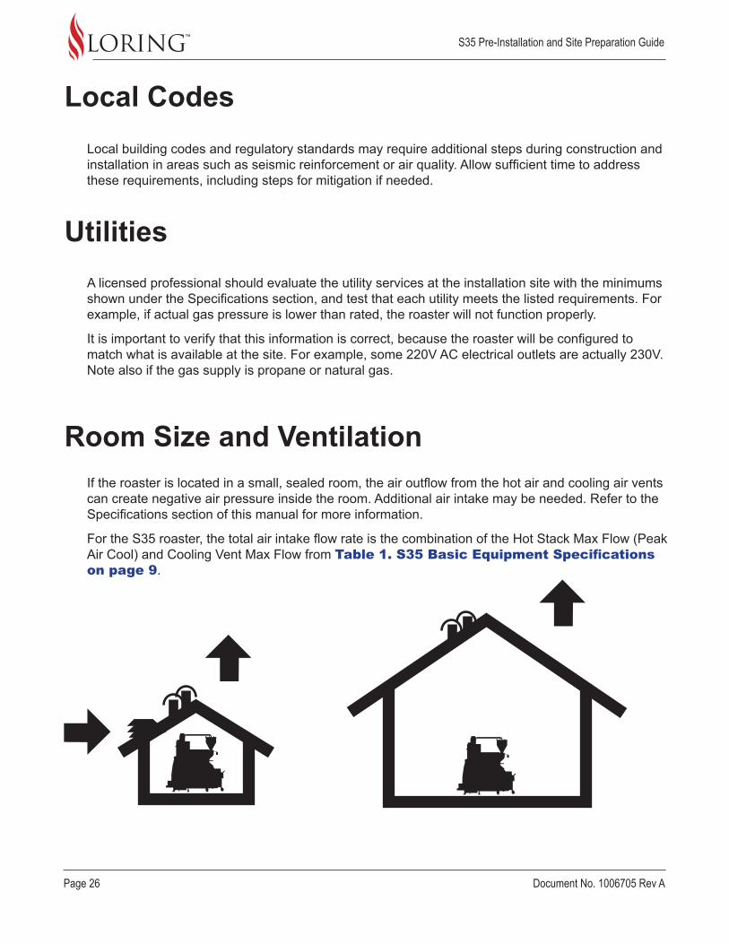
If the roaster is located in a small, sealed room, the air outflow from the hot air and cooling air vents can create negative air pressure inside the room. Additional air intake may be needed. Refer to the Specifications section of this manual for more information.
For the S35 roaster, the total air intake flow rate is the combination of the Hot Stack Max Flow (Peak Air Cool) and Cooling Vent Max Flow from Table 1. S35 Basic Equipment Specifications on page 9.
A licensed professional should evaluate the utility services at the installation site with the minimums shown under the Specifications section, and test that each utility meets the listed requirements. For example, if actual gas pressure is lower than rated, the roaster will not function properly.
It is important to verify that this information is correct, because the roaster will be configured to match what is available at the site. For example, some 220V AC electrical outlets are actually 230V. Note also if the gas supply is propane or natural gas.
S35 Pre-Installation and Site Preparation Guide
Document No. 1006705 Rev A Page 27
Multi-Story Buildings
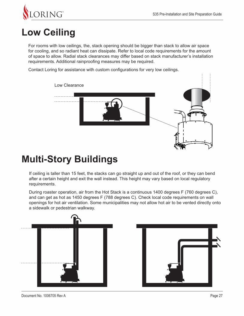
Low CeilingFor rooms with low ceilings, the, stack opening should be bigger than stack to allow air space for cooling, and so radiant heat can dissipate. Refer to local code requirements for the amount of space to allow. Radial stack clearances may differ based on stack manufacturer’s installation requirements. Additional rainproofing measures may be required.
Contact Loring for assistance with custom configurations for very low ceilings.
If ceiling is taller than 15 feet, the stacks can go straight up and out of the roof, or they can bend after a certain height and exit the wall instead. This height may vary based on local regulatory requirements.
During roaster operation, air from the Hot Stack is a continuous 1400 degrees F (760 degrees C), and can get as hot as 1450 degrees F (788 degrees C). Check local code requirements on wall openings for hot air ventilation. Some municipalities may not allow hot air to be vented directly onto a sidewalk or pedestrian walkway.
Low Clearance

S35 Pre-Installation and Site Preparation Guide
Page 28 Document No. 1006705 Rev A
Workflow SpaceWorkflow refers to the smooth operation of one or more personnel within the same physical space. Both access and lighting should be considered. Some of the main access areas are shown below from the top down. Note that some controls are at eye level, while others are at floor level.
Consolet and Power Switches
Roaster
Chaff Barrel
Cyclone
Filters (Mini Cyclone
Green Bean Cart
Cooling Tray + Tryer
(The “Tryer” is a small scoop used for sampling beans during roasting.)
Green Bean Storage Area (example placement)
Green Bean Hopper
Air, Water, and Gas
Destoner Controls
Destoner Power Switch
Destoner
S35 Pre-Installation and Site Preparation Guide
Document No. 1006705 Rev A Page 29
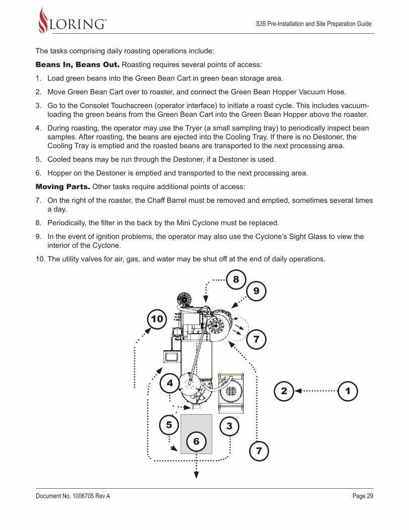
The tasks comprising daily roasting operations include:
Beans In, Beans Out. Roasting requires several points of access:
1. Load green beans into the Green Bean Cart in green bean storage area.
2. Move Green Bean Cart over to roaster, and connect the Green Bean Hopper Vacuum Hose.
3. Go to the Consolet Touchscreen (operator interface) to initiate a roast cycle. This includes vacuum-loading the green beans from the Green Bean Cart into the Green Bean Hopper above the roaster.
4. During roasting, the operator may use the Tryer (a small sampling tray) to periodically inspect bean samples. After roasting, the beans are ejected into the Cooling Tray. If there is no Destoner, the Cooling Tray is emptied and the roasted beans are transported to the next processing area.
5. Cooled beans may be run through the Destoner, if a Destoner is used.
6. Hopper on the Destoner is emptied and transported to the next processing area.
Moving Parts. Other tasks require additional points of access:
7. On the right of the roaster, the Chaff Barrel must be removed and emptied, sometimes several times a day.
8. Periodically, the filter in the back by the Mini Cyclone must be replaced.
9. In the event of ignition problems, the operator may also use the Cyclone’s Sight Glass to view the interior of the Cyclone.
10. The utility valves for air, gas, and water may be shut off at the end of daily operations.
2 1
10
3
4
5
7
76
89
S35 Pre-Installation and Site Preparation Guide
Page 30 Document No. 1006705 Rev A
Lighting
Network
A minimum level of lighting should be available on all sides of the roaster, at all levels including overhead and underneath.
The roaster has the capability of connecting to an existing hard-wired Ethernet network. This allows you to monitor and control the roaster remotely from a desktop or laptop computer, email roaster data and machine fault reports, as well as upload, download and save Roast Profiles.
Customers must determine their own network configuration prior to final site commissioning, and must be able to provide this information to the Loring Field Service Technician.

S35 Pre-Installation and Site Preparation Guide
Document No. 1006705 Rev A Page 31
Shipping the roaster according to Loring’s guidelines is required in order to maintain product warranty.
Receiving Shipment
Shipping Notes
Pallet Jack 2 People Forklift
S35 Minimum Capacity 2000 lbs
The customer is responsible for shipping arrangements, after notification from Loring that the roaster is ready to be picked up for shipping. In particular, the customer should comply with the following guidelines:
• Be sure to state that the roaster is to travel on a vehicle equipped with air ride suspension to dampen the vibration and minimize the chance of damage during shipment.
» For a cross-country shipment within the United States, Loring will not load the roaster equipment onto a trailer that does not have air ride suspension.
» For overseas shipments, request a nose / front load in order to minimize loading and unloading at multiple terminals along the way, which will reduce the opportunity for potential damage.
• Overseas customers are advised to use a Full Container Load (FCL) shipment as this will minimize the amount of transfers and handling by others.
• Handle the crates according to markings on crate for “This Side Up” and “Heavy End”.

S35 Pre-Installation and Site Preparation Guide
Page 32 Document No. 1006705 Rev A
Frame and Body Crate #1
Roaster
Heavy End
Auto Hopper Blower (detached)
Center of gravity
S35 Crate #1
Crate Weight: 400 lbs (182 kg)
Total Shipping Weight: 2000 lbs (908 kg)
51 in (130 cm)
89 in (226 cm)
S35 Shipping Configuration
99 in (252 cm)
S35 Pre-Installation and Site Preparation Guide
Document No. 1006705 Rev A Page 33
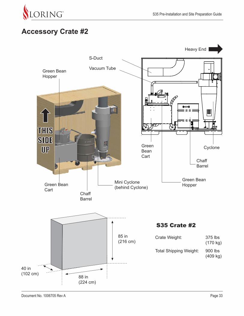
Crate Weight: 375 lbs (170 kg)
Total Shipping Weight: 900 lbs (409 kg)
Accessory Crate #2
S-Duct
Vacuum Tube
Cyclone
Chaff Barrel
Chaff Barrel
Green Bean Hopper
Green Bean Hopper
Green Bean Cart
Green Bean Cart
Mini Cyclone (behind Cyclone)
S35 Crate #2
88 in (224 cm)
40 in (102 cm)
85 in (216 cm)
Heavy End
S35 Pre-Installation and Site Preparation Guide
Page 34 Document No. 1006705 Rev A
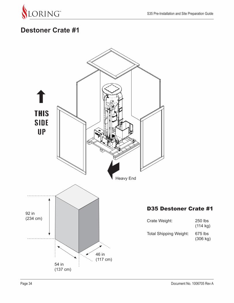
Destoner Crate #1
D35 Destoner Crate #1
54 in (137 cm)
46 in (117 cm)
92 in (234 cm) Crate Weight: 250 lbs
(114 kg)
Total Shipping Weight: 675 lbs (306 kg)
Heavy End
S35 Pre-Installation and Site Preparation Guide
Document No. 1006705 Rev A Page 35
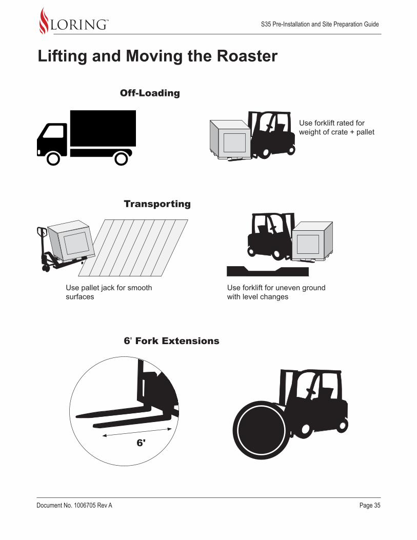
Lifting and Moving the Roaster
Off-Loading
Transporting
6' Fork Extensions
Use pallet jack for smooth surfaces
Use forklift for uneven ground with level changes
6'
Use forklift rated for weight of crate + pallet

S35 Pre-Installation and Site Preparation Guide
Page 36 Document No. 1006705 Rev A
Handling
Inspecting
For side loading, always load “Heavy End” inwards
Tilt indicator shows color above line if crate has tipped
Shock indicator changes color if crate has been dropped or impacted
Each crate ships with 2 shock indicators and 2 tilt indicators. Inspect crates for damage at time of delivery. Note any shipping damage on the Bill of Lading. Refer to the instructions on the indicators for detecting damage.
WARNING: Always keep shipping crates upright during handling and storage.
S35 Pre-Installation and Site Preparation Guide
Document No. 1006705 Rev A Page 37
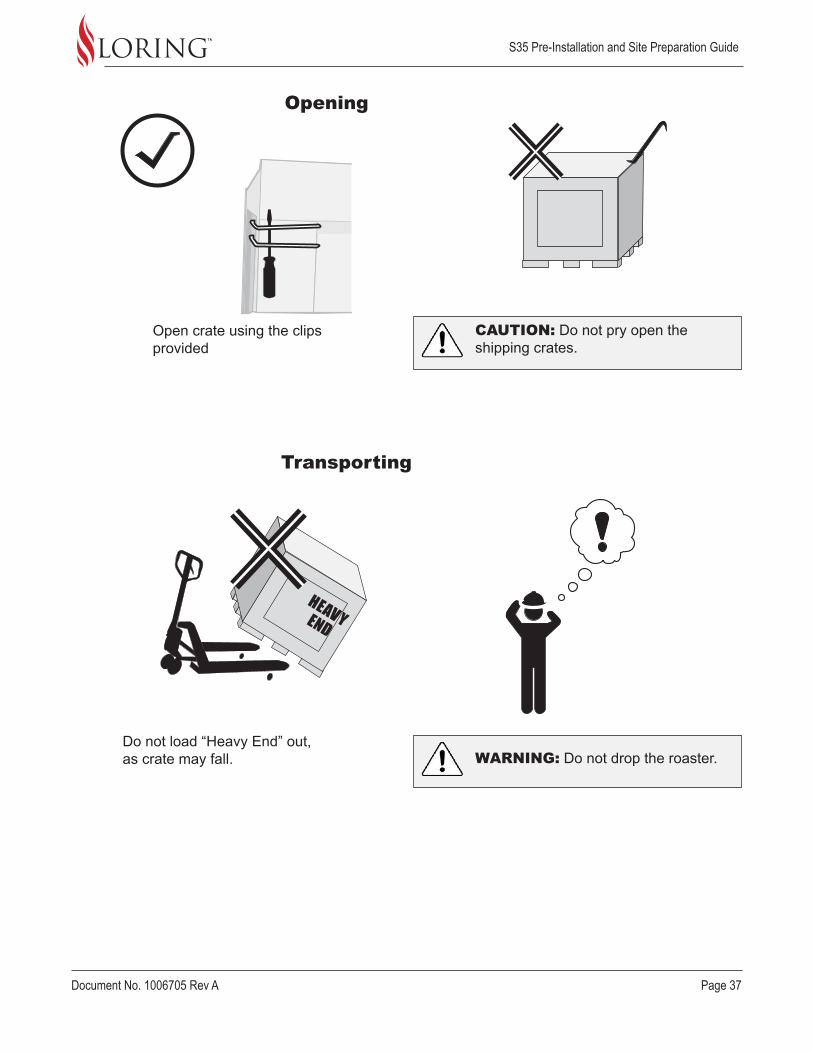
Transporting
Opening
Open crate using the clips provided
Do not load “Heavy End” out, as crate may fall.
CAUTION: Do not pry open the shipping crates.
WARNING: Do not drop the roaster.

S35 Pre-Installation and Site Preparation Guide
Page 38 Document No. 1006705 Rev A
Next Steps
Site Preparation Checklist
After confirming the shipping date with Loring, the customer should:
1. Review the Assembly and Installation Guide and the Mechanical Interface Control Documents (MICDs), available from Loring.
2. Provide the roaster model’s Pre-Installation Guide, the Assembly and Installation Guide, a copy of the customer’s completed Product Specification Form, and the Mechanical Interface Control Document drawings to the licensed contractor responsible for roaster assembly and installation.
Use the following informal checklist to ensure that the site is fully prepared:
Building meets footprint and clearance requirements for selected roaster model
Building doorways, elevators and corridors can accommodate the roaster
Roaster location is clearly marked
Stack hookup locations exist and are marked
Site Detail/Construction Drawings are completed, accurate, and available
Destoner position has been determined and marked, if applicable
Local code requirements are known, and have been addressed
Required permits have been obtained
Both the moving equipment and the final installation location can handle system weight
Air, Gas, and Electric Utilities have been measured and verified to be within required ranges
S35 Pre-Installation and Site Preparation Guide
Document No. 1006705 Rev A Page 39
Manufacturer Contact Information
This equipment is manufactured by:
Loring Smart Roast, Inc. 3200 Dutton Ave #413 Santa Rosa, CA 95407 (707) 526-7215
For questions, please contact Loring Customer Support:
www.loring.com/support
(707) 526-7215 x 217