PRE-ENGINEERED STRUCTURES: SHORT AIRFIELD FOR … · CHAPTER 11 PRE-ENGINEERED STRUCTURES: SHORT...
28
CHAPTER 11 PRE-ENGINEERED STRUCTURES: SHORT AIRFIELD FOR TACTICAL SUPPORT The Short Airfield for Tactical Support (SATS) is a rapidly constructed expeditionary airfield that can be erected near a battle area to provide air support for amphibious Marine forces. In any land-and-sea military/contingency operation, the rapid assembly of a temporary airfield provides ground units with the distinct advantage of continuous air support on foreign soil. Because of this, the Marine Corps has been trying several types of expeditionary airfields since early in World War II. Initial research used wooden planking for the runway surface. Later, during the Korean Conflict, aircraft actually landed on pierced steel mats, known as “Marston matting.” One of the more important breakthroughs in SATS research was the development of Short Expeditionary Landing Field (SELF). SELF, a bulky predecessor of SATS, was a 4,000-foot runway that served as the landing area. In earlier expeditionary arresting operations, the Marine Corps had been successful with the M-2 Mobile Arresting Gear (MOREST). However, the weight of this gear (74,000 pounds) decreased its usefulness as a portable unit. In 1956, the Commandant of the Marine Corps established exact specifications for the development of a portable expeditionary airfield. This proposed airfield was to be 1,000 feet long, construction completed in 5 days, and capable of accommodating one squadron of aircraft for 30 days. Additionally, the Marine Corps required that the field be designed to allow both launch and recovery (arresting) operations. These standards included the development of a land-based catapult and lighter arresting gear to replace the M-2 MOREST. In 1958, the runway specification was expanded to 2,000 feet and received official SATS designation. However, because the catapult and arresting gear are no longer available in the ABFC (Advanced Base Functional Components) System, they are not discussed in this chapter. Because Steelworkers can be assigned to crews assigned to place airfield matting, we will discuss the important parts of SATS. Also, the proper placement procedures for AM-2 matting are discussed and information is also provided on the installation and repair and removal of AM-2 mating. PARTS OF SATS FIELD A SATS field incorporates numerous parts. We will not attempt to cover all the parts of a SATS installation but will cover enough to make you familiar with the function of each of the major parts that make a SATS field an effective system. AM-2 MATTING The AM-2 mat (fig. 1 l-l) is a fabricated aluminum panel, 1 1/2 inches thick that contains a hollow, extruded, one-piece main section with extruded end connectors welded to each end. (AM-2 mats may also be fabricated in two- and three-piece main panel extrusions that, when welded longitudinally, form the same size and shape as the one-piece extrusion.) The AM-2 mat comes in full sheets and half sheets and is painted Marine Corps green. The top surface is coated with a nonskid material of the same color. For runways and taxiways, the mats are installed in a brickwork type of pattern. The staggered joint arrangement provides the required stability across the runway and the necessary flexibility in the direction of aircraft travel. Figure 11-1.—AM-2 mat. 11-1
Transcript of PRE-ENGINEERED STRUCTURES: SHORT AIRFIELD FOR … · CHAPTER 11 PRE-ENGINEERED STRUCTURES: SHORT...
CHAPTER 11
PRE-ENGINEERED STRUCTURES: SHORT AIRFIELDFOR TACTICAL SUPPORT
The Short Airfield for Tactical Support (SATS) isa rapidly constructed expeditionary airfield that canbe erected near a battle area to provide air support foramphibious Marine forces. In any land-and-seamilitary/contingency operation, the rapid assembly ofa temporary airfield provides ground units with thedistinct advantage of continuous air support on foreignsoil. Because of this, the Marine Corps has been tryingseveral types of expeditionary airfields since early inWorld War II. Initial research used wooden plankingfor the runway surface. Later, during the KoreanConflict, aircraft actually landed on pierced steel mats,known as “Marston matting.”
One of the more important breakthroughs in SATSresearch was the development of Short ExpeditionaryLanding Field (SELF). SELF, a bulky predecessor ofSATS, was a 4,000-foot runway that served as thelanding area. In earlier expeditionary arrestingoperations, the Marine Corps had been successful withthe M-2 Mobile Arresting Gear (MOREST).However, the weight of this gear (74,000 pounds)decreased its usefulness as a portable unit.
In 1956, the Commandant of the Marine Corpsestablished exact specifications for the developmentof a portable expeditionary airfield. This proposedairfield was to be 1,000 feet long, constructioncompleted in 5 days, and capable of accommodatingone squadron of aircraft for 30 days. Additionally, theMarine Corps required that the field be designed toallow both launch and recovery (arresting) operations.These standards included the development of aland-based catapult and lighter arresting gear toreplace the M-2 MOREST. In 1958, the runwayspecification was expanded to 2,000 feet and receivedofficial SATS designation. However, because thecatapult and arresting gear are no longer available inthe ABFC (Advanced Base Functional Components)System, they are not discussed in this chapter.
Because Steelworkers can be assigned to crewsassigned to place airfield matting, we will discuss theimportant parts of SATS. Also, the proper placementprocedures for AM-2 matting are discussed and
information is also provided on the installation andrepair and removal of AM-2 mating.
PARTS OF SATS FIELD
A SATS field incorporates numerous parts. Wewill not attempt to cover all the parts of a SATSinstallation but will cover enough to make youfamiliar with the function of each of the major partsthat make a SATS field an effective system.
AM-2 MATTING
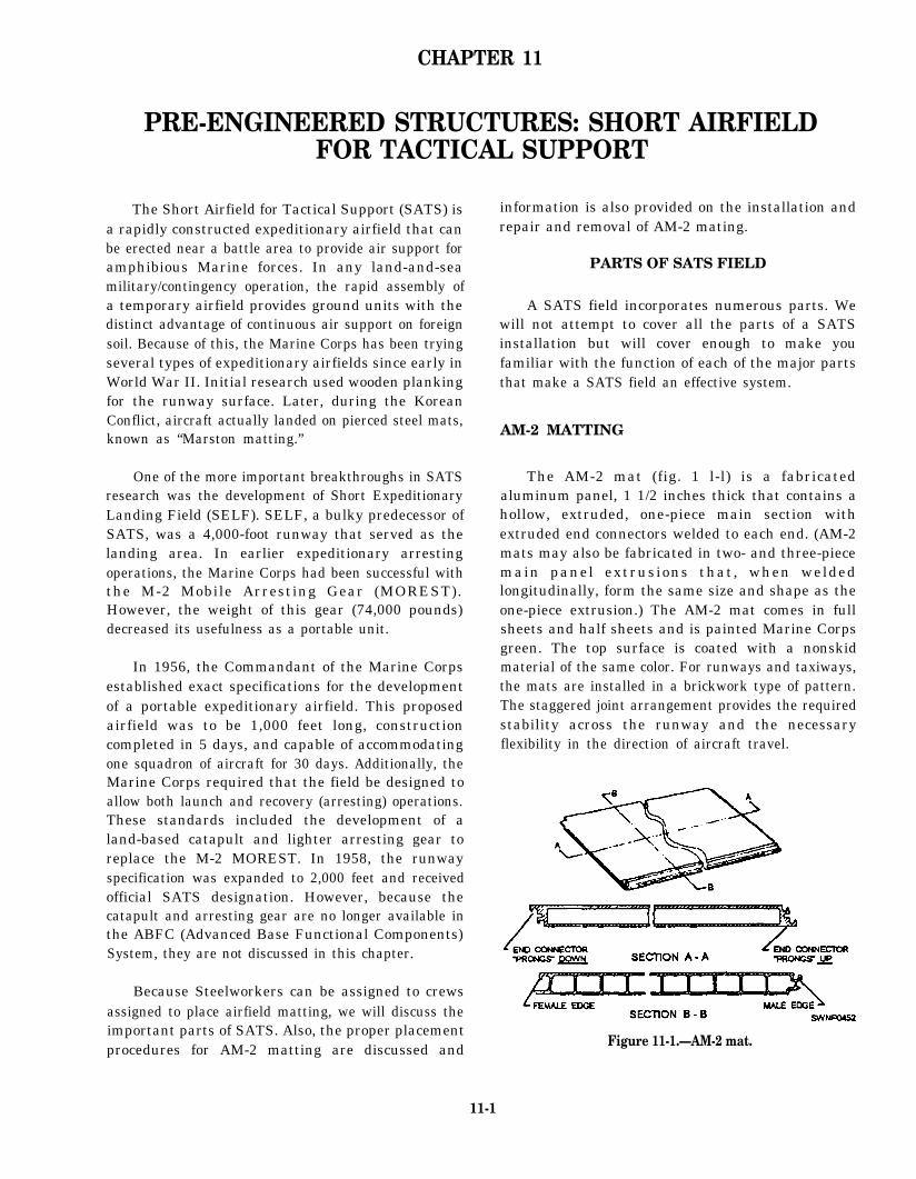
The AM-2 mat (fig. 1 l-l) is a fabricatedaluminum panel, 1 1/2 inches thick that contains ahollow, extruded, one-piece main section withextruded end connectors welded to each end. (AM-2mats may also be fabricated in two- and three-piecemain panel extrusions that, when weldedlongitudinally, form the same size and shape as theone-piece extrusion.) The AM-2 mat comes in fullsheets and half sheets and is painted Marine Corpsgreen. The top surface is coated with a nonskidmaterial of the same color. For runways and taxiways,the mats are installed in a brickwork type of pattern.The staggered joint arrangement provides the requiredstability across the runway and the necessaryflexibility in the direction of aircraft travel.
Figure 11-1.—AM-2 mat.
11-1

The sides of the mat panels are constructed tointerlock with a rotating motion. The end connectorsare arranged with the prongs up on one end and downon the other (fig. 11-1, section A-A). By placing theend connector of one mat properly over the endconnector of the previous mat, you can form acontinuous layer of matting. A flat-locking bar is theninserted into the slot common to the two mats to forma nonseparable joint.
The physical characteristics of AM-2 matting areshown in table 11-1.
AM-2 mats are packaged in two standard palletloads for storage and shipment. One pallet assembly,designated F11, consists of 11 full-length mats, 2half-length mats, and 13 locking bars (fig. 11-2). Theother mat pallet, designated F15, contains 16 full-lengthmats, 4 half-length mats, and 20 locking bars(fig. 11-3). The pallets are fabricated end frames thatare held together by tie rods or strapping. The endframes fit around the ends of the mats and become thestorage place for the locking bars.
The quantity of mats found in the standard palletassembly (F11) provides a width of two rows (4 feet)on a runway or taxiway that is 72 feet wide. For widthsother than 72 feet, more or less coverage (in terms ofstrip length) is obtained. Since the parking and storageareas need not have a specific mat pattern, as isrequired on the runways and taxiways, the “extra”half-length of full-length mats that result from therunway construction may be used in these areas. Theuse of a guide rail and/or keylocks will not affect theamount of coverage to any great extent.
INSTALLATION
As a Steelworker, you can be assigned to a projectplacing AM-2 mats for airfield surfaces; therefore,you need to be familiar with the procedures used forinstalling mats. Primary operations involving sitepreparation and pallet staging are also discussed.Additionally, information on manpower requirementsand the organizational structure of the installationcrew is presented.
Site Preparation
‘he soil and subbase materials of the site selectedas the SATS field must be suitable for use with theAM-2 landing mats. The subbase material must havea minimum compaction of 95 percent, and theengineering staff will provide you further guidancebased on their analysis of the soil type and theavailable base materials.
The operations that are part of the site preparationthat must be completed before mats are installed areas follows:
1. The terrain in the area to be used must becleared, leveled, and rolled to provide the designatedcompaction for the matting base. Grading must provideadequate drainage of water away from the field area andthe soil must be disturbed as little as possible inobtaining the prescribed finish. These operations willprovide a soil having a maximum bearing capacity.
2. The soil in any area under the matting, requiringinstallation of service, drainpipes, or other objects, mustbe backfilled and thoroughly compacted
Table 11-1.—Physical Characteristics of AM-2 Matting
11-2

Figure 11-2.—F11 AM-2 full-length pallet.
3. The final grading operation must be adequatelylevel so mats, when laid, do not vary more than l/4inchin height over a 12-foot distance.
4. Hand raking is necessary to remove small rocksand other debris that would hinder this task as well asthe connecting of mats.
5. The overall field configuration must be stakedout in its entirety. Accurate longitudinal and transversecenter lines must be established to ease the staging ofthe pallets. When no guide rail is used, both lateralrunway edges must be accurately marked to ensuresmooth linear edges from which to lay the mat field. Theline for the edges of the runway is determined by usinga transit and marking them clearly with a chalk line orstakes. This type of survey is also required whentaxiways and parking areas are installed. When a guide
rail installed, only the center line of the guide rail isestablished by transit.
NOTE: Site preparation may not be required ifthere is an existing concrete or asphalt runway becausematting can be laid over the existing hard surface.
Pallet Staging
Under combat/contingency operations, palletsmust be staged in a manner to keep manual handlingto a minimum. Additionally, staging should maximizeall available equipment and manpower coupled withconsideration for the climatic conditions in which theconstruction is started
Different methods are used for the staging ofpallets. The most efficient method is the staging of
11-3

Figure 11-3.—Fl5 AM-2 full-length pallet.
pallets by rough-terrain forklifts. This method is themost eflicient because the forklift can deliver thepallets directly to the mat-laying crews whodisassemble the pallets on the forklift. Palletdisassembly is done at the work area, rather than thestorage point, because the mats could be dropped anddamaged while being moved if they are uncrated andmoved in a loose configuration. The forklift remainson site until the pallet load has been installed. Thismethod presumes that an adequate number of forkliftsare available to resupply the laying crewscontinuously. Round-trip time between the work areaand the pallet storage area must be considered to keepthe work flowing smoothly and completed in a time] ymanner.
The primary rough-terrain forklift used in theNCF is the 4K rough-terrain forklift (fig. 11-4). Adiesel engine-driven, self-contained, material-
handling vehicle, the 4K forklift is designed primarilyfor the rough-terrain handling and warehousing ofmaterials. The 4K forklift can lift and carry loads upto a maximum of 4,000-pound capacity and is the idealequipment to use for staging pallets. The hydraulicallyoperated forklift mechanism, mounted on the extremefront of the vehicle, eases the lifting, reaching, tilting,and sliding of loads during material-handlingoperations.
AM-2 matting in its palletized configuration isvulnerable to damage resulting from improperhandling. Lifting eyes are contained in the pallet endframes to receive the sling lifting hooks. Under NOcircumstances should “choker” type of slings be usedbecause these damage matting side connectors.Normal cargo-handling precautions must be usedduring AM-2 pallet assembly handling.
11-4

Figure 11-4.—4K rough-terrain forktlift.
PaIlet components are vulnerable to damage bymisuse of tools, such as cutting torch, bolt cutters, andsledge hammers. Therefore, extreme care must beused during pallet disassembly. No spare componentsare packaged in the pallet.
Installation Crew
Field experience dictates that a 16-man crewprovide maximum efficiency and flexibility whenlaying a runway 96 feet in width. Two crews can beused inlaying a runway and additional crews used forlaying other areas simultaneously. A typical crew of16 would include 1 petty officer in charge, 1 alignmentperson, 2 pry bar crew members, and 12 (six 2-personteams) mat installation personnel.
The alignment person ensures the field is alignedby adjusting the first mat in each transverse row, so itis flush with the presurveyed lateral boundary beforethe rest of the mats in that row are laid.
The pry bar crew members adjust individual mats,using a pry bar to provide maximum allowance forthermal expansion and insert the mat-locking bars.
The installation pesonnel, working with partners,take a mat from the pallet, carry it to the installationpoint, and then install the mat in place.
SATS Field Installation Sequence
The sequence of laying matting for a runwaywhere a guide rail for a catapult system is not requiredis not the same as for a runway where a guide rail isrequired. Figure 11-5 shows you what a guide rail
looks like. When a catapult facility is used with aSATS installation, a guide rail is needed to providestability to the dolly and the aircraft during the launch.The guide rail is supplied in 9- and 10-foot lengths andhas connectors on both sides to mate with the mat endconnectors. A l/8-inch rubber seal is installed betweeneach section to provide for thermal expansion and toprevent debris and soil from coming up between therail sections. Dowel pins are used between two holesin the mats at each end of the guide rails to maintainalignment of the sections. The guide rail is installedconcurrently with the mat field, and standardmat-locking bars are used to secure it to the mats.
NOTE: The catapult and arresting system is notavailable currently in the ABFC System. However, itwas originally designed for the ABFC System andcould be used in the future; therefore, information onguide rails is provided.
Figure 11-5.—Guide rail.
11-5

Figure 11-6.—AM-2 mat installation sequence without a guide rail.
The general sequence of laying matting for any the mat interlock design which is such that reversinglength of installation where a guide rail is not required the procedure is difficult and inefficient. The coatedis to start at the transverse centerline and work toward side is always “up,” and the interlocking prongs on theeach end simultaneously. The starter keylock section 2-foot edge are always to the right and up. Survey linesis laid, and then individual mats are laid in a brickwork are present to guide at least one edge of the sectiontype of pattern from left to right when facing the being laid to maintain proper longitudinalworking area. The left-to-right sequence is dictated by alignment. Other sections of the site maybe laid in
11-6
the same reamer and at the same time if survey lineshave been established, pallet staging has beenaccomplished, and sufficient personnel are available.A typical keylock section is laid every 100 feet,starting with the 100-foot mark on either side of thestarter keylock.
The general sequence of laying mating for therunway with the guide rail installed is to start at oneend (at the approach apron) and work toward theopposite end. The guide rail divides the runway intotwo sections, 18 feet and 78 feet (or 18 feet and 30 feetfor a 48-foot runway). Individual mats are laid in abrickwork type of pattern from the guide rail to theouter edge in each section when facing the workingarea. The starter keylock is not used when laying arunway with a guide rail. Instead, typical keylocks arelaid at 100-foot intends on the runway, and othersections of the SATS field are laid as explained in theprevious paragraph.
Be sure to inspect visually upturned sides and endconnectors of AM-2 matting for foreign matter beforeplacing them in position. The presence of dirt, chips,stones, and so on, can prevent proper interlocking ofthe mats. Brooms or brushes can be used to cleanforeign matter from the connectors.
Mat-Laying Procedure withouta Guide Rail
The sequence for installing AM-2 mats and relatedcomponents where a guide rail is not required is shownin figure 11-6. The sequence can be modified, so workproceeds on only one row of mats at any given time;however , SPEED OF INSTALLATION ISIMPORTANT. The sequence, as shown in figure 11-6,allows the use of at least two crews with six 2-manteams on each crew carrying and placing mats andkeylocks.
When placing AM-2 mats, you should have threetypes of keylocks: starter, typical, and female. Youshould use a step-by-step procedure to place the AM-2mats.
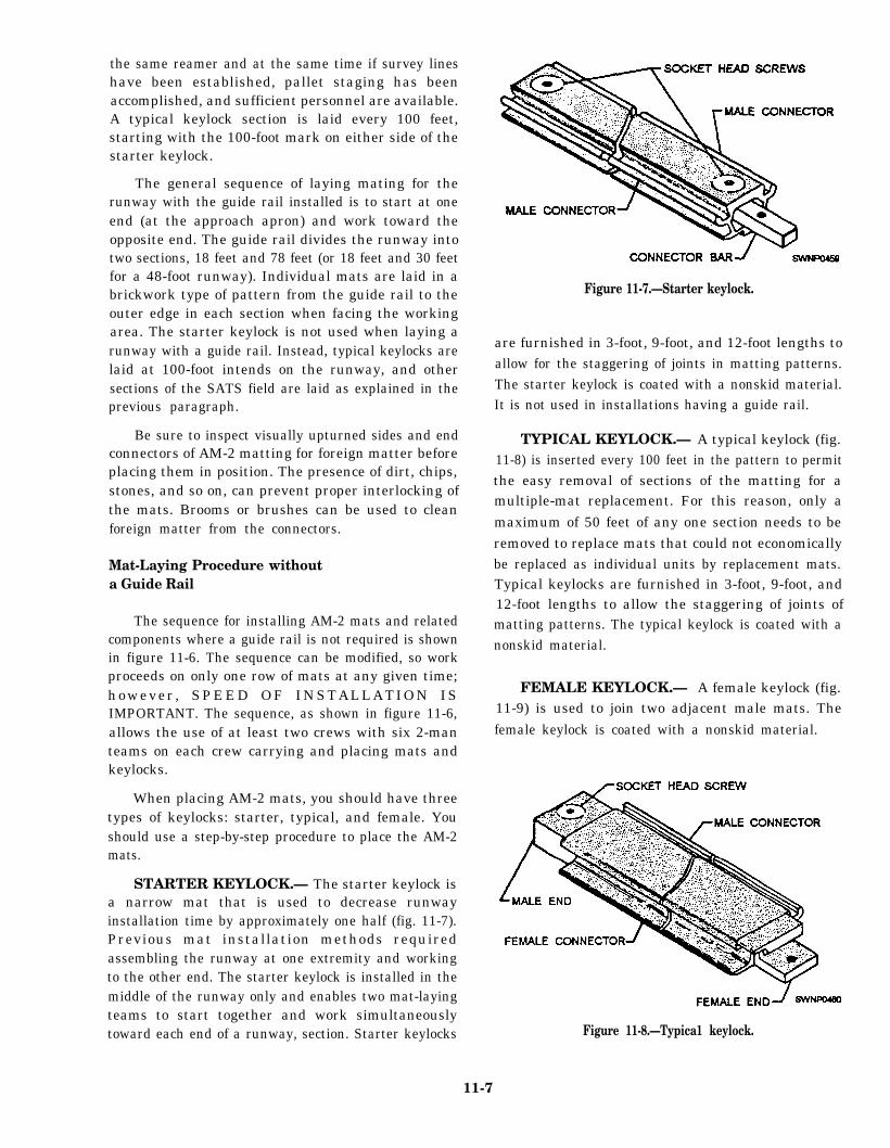
STARTER KEYLOCK.— The starter keylock isa narrow mat that is used to decrease runwayinstallation time by approximately one half (fig. 11-7).Previous mat installation methods requiredassembling the runway at one extremity and workingto the other end. The starter keylock is installed in themiddle of the runway only and enables two mat-layingteams to start together and work simultaneouslytoward each end of a runway, section. Starter keylocks
Figure 11-7.—Starter keylock.
are furnished in 3-foot, 9-foot, and 12-foot lengths toallow for the staggering of joints in matting patterns.The starter keylock is coated with a nonskid material.It is not used in installations having a guide rail.
TYPICAL KEYLOCK.— A typical keylock (fig.11-8) is inserted every 100 feet in the pattern to permitthe easy removal of sections of the matting for amultiple-mat replacement. For this reason, only amaximum of 50 feet of any one section needs to beremoved to replace mats that could not economicallybe replaced as individual units by replacement mats.Typical keylocks are furnished in 3-foot, 9-foot, and12-foot lengths to allow the staggering of joints ofmatting patterns. The typical keylock is coated with anonskid material.
FEMALE KEYLOCK.— A female keylock (fig.11-9) is used to join two adjacent male mats. Thefemale keylock is coated with a nonskid material.
Figure 11-8.—Typica1 keylock.
11-7

Figure 11-9.—Female keylock.
Steps for Laying AM-2 Mats and Keylocks
The procedure for laying AM-2 mats and keylocksis shown in figures 11-10 through 11-18 and consistsof the following steps:
1. Lay starter keylocks on the transverse centerline of the runway. (See fig. 11-10.) A 9-foot starterkeylock is laid at the outer edge of the runway. Removethe socket head screws from the keylock to allow forextending the locking bars into the next keylock section.
2. Place a 12-foot starter keylock next to, andaligned with, the 9-foot section. Move the 12-footsection against the 9-foot section, and adjust the lockingbar so the socket head screws secure the locking bar ineach section this procedure secures the 9-foot starterkeylock and the 12-foot starter keylock, as shown indetail “A” of figure 11-10.
3. Repeat laying six more 12-foot sections and one3-foot section of starter keylocks to complete the96-foot width of the runway.
NOTE: Initially, lay several transverse rows ofAM-2 matting in one direction only from the starterkeylock row. If matting is started on both sides of thestarter keylock, a seesaw force could result, disturbingthe alignment of the entire field.
4. With the nonskid side of the mat turned up andthe upturned prongs on the right, align the first mat (halfmat) on the left side with the starter keylock (fig. 11-11).Align the downturned prongs with the runway edge.Hook the female edge of the mat into the groove on thestarter keylock (fig. 11-12) while holding the mat in anangular position. Rotate the mat downward to form thejoint. (See fig. 11- 12.)
5. Lay the second and all successive mats the sameway as the first mat (fig. 11-11) in relation to the starterkeylock. The downturned prongs of the second matshould mate with the upturned prongs of the first mat,as shown in figure 11-13. When the mats are properlyengaged, a rectangular slot is formed by the engagementof the end connectors.
6. Lock the first and second mats together, asshown in figure 11-14, by inserting the locking bar (fig.11-15).
NOTE: The first two mats and all mats in the firstrow should be aligned accurately before inserting thelocking bar. Misalignment of mats will prevent properinstallation of the second row. Locking bars may stick
Figure 11-10 —Placing starter keylocks on a transverse center line.
11-8

Figure 11-11.—Placing first and second mats
Figure 11-12.—Engaging first half mat (half length) to starter keylock.
because of the natural waviness in the manufacture ofthe mat end connectors and the locking bars. A fewlight taps of a hammer should drive the bar into theproper position.
7. Place the third mat at the start of the second row,as shown in figure 11-16. Ensure that the third mat isaligned on the left side with the mat in the precedingrow. Refer to figure 11-12 and step 4 for the engagementprocedure, which is the same for the engagement of thethird mat with the first and second mats.
NOTE: The first row of mats and each alternaterow thereafter is laid using half mats at the outer edgesof the runway and full mats in between (fig. 11-6). Thesecond row of mats and each alternate row thereafteris laid using full mats only. This method provides astaggered joint for greater matting strength.
8. Complete the first row, installing six morefull-length mats and finally a half mat, using the same
procedure as described for installation of the secondmat. (See step 5.)
NOTE: The first row of mats on the opposite sideof the starter keylock row are all full mats (fig. 11-6).
CAUTION
Align the first row accurately with stakesor guidelines delineating the extent of matting.As work progresses, periodically check thealignment of mats already installed. Anymisalignment causes a displacement of therunway from the planned position at the far endof the field.
9. Install the second and succeeding rowsaccording to the procedure for the third mat (first matin the second row) with one notable exception. Thesecond mat in each row must first be hooked to the
11-9

Figure 11-13.—Engagement of the first and second mats.
Figure 11-14.—Locking first and second mat, using locking bar.
11-10

Figure 11-15.—Insertion of the locking bar.
Figure 11-16.—Placing of third mat (full-length).
preceding row while being held at an angle (fig. 11-12).The mat must then be aligned so when it is rotateddownward, the end connectors mate properly, as shownin figure 11-13.
NOTE: The mats are designed with an apparent‘loose fit.” This is to allow for expansion and also toallow for the natural waviness inherent in the extrudedmat sections. Because of this, it is possible to have arow of mats “installed” but misaligned so as to preventthe proper engagement of one or more of the mats inthe following row. (Such a condition in exaggeratedform, and the method of corrections, is shown is figure
11-17.) Locking bars may be used as temporaryspacers between the rows to prevent this. Place alocking bar on edge where the ends of two mats joinand as the row ends. After three or four rows have beenlaid using locking spacers, proceed with the remainderof the runway or taxiway by removing the spacersfrom the furthest row and using them in the row justlaid.
CAUTION
If it becomes necessary towith a sledge, always place a
adjust mattingwooden block
11-11

Figure 11-17.—Correction of mat misalignment.
against the mat edge before striking, as shownin figure 11-17.
10. Every 100 feet, install a row of typical keylocksin the matting field (fig. 11-6). Place a 9-foot typicalkeylock at the outer edge of the runway with the femaleend of the keylock aligned with the first mat of thepreceding row (fig. 11-1 8). Engage the female edge ofthe typical keylock with the male edge of the mat in thepreceding row (similar to fig: 11-12 and step 4).
11. Place a 12-foot typical keylock next to theinstalled 9-foot typical keylock. Move the 12-footsection against the 9-foot section after first engaging thefemale edge of the keylock with the male edge of thefirst twoo mats in the preceding row. Raise the sockethead screw in the male end of the 9-foot keylock untilthe threaded hole in the female end of the 12-foot
keylock is aligned. Then secure the socket head screwin the 9-foot keylock, using the socket head screwwrench.
See detail “A” of figure 11-18 that shows thetypical keylocks secured together. Repeat laying of sixmore 12-foot sections and one 3-foot section of thetypical keylocks to complete the 96-foot width of therunway.
NOTE: After the laying of a row of typicalkeylocks every 100 feet, continue laying AM-2matting, according to steps 4 through 9, to the ends ofthe runway.
Runway APPROACH APRONS are required ateach end of the main runway. These aprons are rampsmade of mats placed to prevent the tail hook of a low
11-12

Figure 11-18.–Placing typical keylocks in a matting field.
incoming aircraft from engaging or hooking onto theedge of the runway. (See fig. 11-19.)
The aprons are constructed in a brickwork type ofpattern but may be entirely of half-length mat unitsand extend across the full width of the runway. Thefree end of the apron should fall a distance of 18 to 24inches below the normal ground level. The groundsurface beneath each mat should be shaped to providefull contact across the bottom of the mat. Afterinstallation of the ramp, the excavation should bebackfilled (ramp covered to the normal ground level).The backfill should be tamped and compacted.
Installation of the ramp at the starting end of therunway can be readily accomplished although theinstallation procedure is slightly different. Place theside connector under the overhanging lip of the firstrow of mats and lift until contact is made. The mat isthen rotated downward while keeping the two mats incontact. Locking bars are installed as describedpreviously.
MAT END RAMPS are used at the ends of therunways, laid on a hard surface (concrete), to smooththe passage from one surface to the other. The edgeconnection between the ramp and mat sections is thesame as between two rows of matting. The ramp isfabricated from aluminum extrusions and is providedwith welded inserts and extension plates, drilled andtapped to allow the ramp sections to be joined andanchored. (See fig. 11-20,)
When installing mat end ramps, you should usethe following procedure:
1. Install the first ramp at the right-hand corner,looking toward the opposite end of the runway. Placethe next ramp adjacent to it, ensuring that holes in theoverlapping plate on the ramp line up with threadedinserts on the matting ramp. Insert five flathead screwsin each ramp, using the Allen wrench provided in thetoolbox. Apply antiseize compound to the screwthreads.
2. Next, use the locking baron the edge betweenthe ramps and edges of the mats to assure the alignmentis straight.
3. As the ramps are placed and screwed together,drill holes in the concrete for lag screw shields, usingthe holes in each ramp as a template. Drill holes to5/8-inch diameter and 3 inches deep with the drill bitfrom the toolbox. Insert an expansion shield in each holedrilled in the concrete. Insert a lag bolt and washer ineach counterbored hole. Tighten the lag bolts with theoffset, square box-end wrench provided in the toolbox.
4. Complete the end ramp installation, as shown infigure 11-21.
Mat-Laying Procedure with a Guide Rail
The sequence for installing AM-2 mats and relatedcomponents where a guide rail for a catapult system isrequired is shown in figure 11-22. The guide raildivides the runway into an 18-foot and a 78-foot
11-13

Figure 11-19.—Laying of runway approach apron
Figure 11-20.—Mat end ramp.
11-14

Figure 11-21.—Placememt of mat end ramps.
section. The laying of matting should proceed in onedirection only, from one end of the runway. Laying ofthe guide rail, mats, and related components is asfollows:
NOTE: The instructions presented here are for a96-foot runway, but they are also applicable for a48-foot runway.
1. Establish the guide rail center line, using atransit.
2. Install the first guide rail with dowel pins facingaft (opposite the direction of laying the guide rails). Thefirst guide rail should be 9 feet in length, NAEC (NavalAir Engineering Center) Part No. 6125354, to preventalignment of the guide rail joint with the mat joint.
3. Install the next four guide rails (10-foot rail)using spacer seals, NAEC Part No. 414233-1, and gapgauges, NAEC Part No. 414219-1, between the guiderail joints before driving the dowel pins. Check forproper position of the pins in the guide rails, using a pingauge, NAEC Part No. 414212-1.
NOTE: As the guide rails and mats are being laid,any visible depressions in the grade should be filled inand raked with the applicable hand tools.
4. Insert the transit target, NAEC Part No.
414691-1, in the center slot of the guide rail andpreliminary alignment of each rail.
5. Lay the 18-foot section of AM-2 matting, as
shown in figure 11-22. Insert the mat-locking barsbetween the guide rail and the mat. (See fig. 11-23.)
6. Insert the transit target, NAEC Part No.414691-1, in the center slot of the guide rail and make
the final alignment by shifting the five guide rails andattached mats. The guide rails and mats maybe shifted
by pounding the edge of the guide rail or mat with awooden block and a mallet. The guide rail center lineshould not vary more than 1/4 inch in 50 feet in the
horizontal direction nor more than 1/8 inch in 12 feet inthe vertical direction as determined by a 12-foot
straightedge. The straightedge should be moved in6-foot increments.
11-15

Figure 11-22.—AM-2 mat installation sequence (with guide rails—96-foot-wide runway).
7. Begin laying the 78-foot side of matting for thelength of the guide rail and matting as aligned in step 6.Transverse mat joints should not vary more than 3inches between the 18-foot and 78-foot-wide section ofthe runway where joints meet the guide rail and the mat.Installation of the 78-foot side may lag behind the guiderail and the 18-foot side but should never be installedbeside the guide rails that have not yet been alignedaccording to step 6.
8. Install the next five guide rails. Guide rail jointsshould never be closer than 3 inches in reference to thetransverse mat joints. (See fig. 11-23.) To ensure the3-inch distance between the mat and guide rail joints,
substitute a 9-foot length of guide rail for a 10-footguide rail. Lay matting on the 18-foot side and then the78-feet side. (See steps 5,6, and 7.) Continue installingthe runway until 100 feet of the matting has been laid.
NOTE: A minimum of ten gap gauges shouldremain installed to the rear of the guide rail dowel pinsbeing installed.
9. Every 100 feet, install typical keylocks acrossthe runway. Typical keylocks cannot be secured to theguide rail. Cut keylocks in 6-foot sections, as necessary,to ease installation on the 18-foot and the 78-foot sidesof the guide rail. Refer to the section discussedprevious] yin this chapter on “Mat-Laying Procedures
11-16

Figure 11-23.—Laying of guide rails and mats.
without a Guide Rail,” steps 10 and 11, for typical are 12-foot-long aluminum “H” sections that allow
installation of keylocks in the field
10. Install approach aprons at both ends of the
runway. Use 90-degree connectors to join the approach
aprons to the field matting. (See fig. 11-24.) Connectors
Figure 11-24 .—90-degree connector.
relative movement and slight misalignment between theadjoining sections of matting.
Field-Laying Procedure
The sequence for laying an entire field is asfollows:
1. The main runway
2. The lateral taxiways
3. The taxiway that is parallel to the runway
4. The parking stands and storage areas
The above sequence may be modified in theinterest of gaining time in the overall installation bylaying the main runway and the parallel runway at thesame time. Then the lateral taxiways and parking areacan be installed.
11-17

CAUTION
If the latter procedure is to be used thedistance between the runway and its paralleltaxiway must be carefully controlled Since themat width is 2 feet, a gap of almost 1 foot couldoccur at each end of the interconnecting lateraltaxiway. The gap between the lateral taxi wayand the long taxiway and runway should notexceed 2 inches.
RUNWAY-TAXIWAY CONNECTIONS.—Install W-degree connectors on the edge of the runwayat the point where the lateral taxiways will connectwith the runway. The 90-degree connectors may beused at other points where two mat-laying patterns, at90 degrees to each other, are to be joined.
NOTE: The 90-degree connectors can be used toconnect the end of the lateral taxiway with the longtaxiway also.
The two procedures for installing 90-degreeconnectors are as follows:
PROCEDURE NUMBER 1. Where theadjoining pattern has not been laid, install a sufficientnumber of 90-degree connectors along the 2-foot edgeof matting, such as the edge of the runway, equal tothe width of the taxi way or other section to be joined.Lay a half-length mat into the first 90-degreeconnector, so the end of the mat matches the end of theconnector. Engage the prongs of a full-length mat intothe prongs of the half-length mat previously laid andpush into engagement with the 90-degree connector.Continue to lay mats in the above manner until the firstrow is completed to the length of the 90-degreeconnectors. Additional mats may then be laid in theusual manner. (See fig. 11-25.)
PROCEDURE NUMBER 2. Where theadjoining mat pattern has already been laid, adjust thelast few rows of matting (of the taxiway), so the space
Figure 11-25.—Procedure No.1, 90-degree connectors.
Figure 11-26.—Procedure No. 2, 90-degree connectors.
11-18

between the runway and the taxiway is between 1 and2 inches. Place a 90-degree connector in position, asshown in figure 11-26. Using a sledge hammer and awooden block, drive it into position. The mostefficient method is to drive the 90-degree connectorsfrom either edge toward the center of the taxiway.Place a mark at or near the midpoint of the 12-footlength of the mat. Drive the first connector to thismark. The positions of the remaining 90-degreeconnectors are then automatically established. Caremust be maintained while driving the connectors notto allow debris to be scooped up by the forward edgesof the connectors.
I N S T A L L A T I O N O F T I E - D O W N S . —The-downs are provided for aircraft anchorage. (Seefig. 11-27.) They are shipped in a package orcontainer, as shown in figure 11-28. An individualcontainer contains 120 tie-downs, plus the screws,drilling, and tapping equipment necessary to installthe tie-downs.
When tie-downs are to be installed, start bydrilling and tapping the AM-2 matting on theprongs-down connector. Drill two holes for eachtie-down ring retainer, using tools from the tie-downcontainer. The procedure for drilling is as follows:
1. Secure the sleeve, 412131-1, to the 5/16-inchdrill with the setscrew, using the drill fixture, 509044-1,as shown in operation 1, figure 11-29. Orient the sleeveto ensure seating of the setscrew on the body diameterof the drill.
2. Position the drill fixture, as shown in operation2 (fig. 11-29), and drill one hole, as shown. Proper depthis obtained when the sleeve contacts the bushing.
3. Insert the pilot, 4121301, through the drillbushing into the drilled hole, and drill the second hole,as shown in operation 3 (fig. 11-29).
Figure 11-27.—Tiedowu
Figure 11-28.—Tie-down container.
4. Tap two holes 3/8 inch, 16 threads per inch,unified national coarse class 3B fit. Finish with thebottom tap to obtain 9/16-inch minimum full-threadlength.
5. Store the sleeve and the pilot in the holesprovided and secure with setscrews.
After the drilling is completed, secure the ringretainer with two socket head screws.
PARKING AND STORAGE AREAS.— Theparking and storage areas should be installed next.Mats and locking bars are installed in the same manneras the runway and taxi ways, except that the staggeredjoint pattern is not mandatory. This means that the areacan be built up in any random pattern and that allleftover half-length or full-length mats can be used.The 90-degree connectors should be installed betweenthese parking and storage areas and taxiwaysaccording to the procedure outlined earlier. Installtie-downs on the matting in these areas, as shown infigure 11-30.
BLAST DEFLECTOR INSTALLATION.— Toshield the ground area around taxiways and parkingareas from the blast effects from aircraft, install blastdeflectors as required. Assemble blast deflectoradapters to the boundaries of matting that will be
11-19

Figure 11-29.—Drilling jig for installing tiedowns
Figure 11-30.—Installing tie-downs in AM-2 matting.
either male edges, female edges, prongs-down ends, MATTING REPAIRor prongs-up ends. Three types of adapters are
supplied to fit anyone of the joints. Erect AM-2 mats During use in the field, matting may becometo the exposed upturned edge of the adapters to damaged and require repair or overhaul. Some of theprovide the blast shield. Use the adapters to support repairs that may be necessary are covered here. If youeach AM-2 mat. (See fig. 11-31.) are called upon to make repairs other than those
11-20

Figure 11-31.—Installation of blast deflector (adapters and mats).
covered below, consult your leading petty officer forinstructions.
INDIVIDUAL MAT REPLACEMENT
If an individual mat is damaged and cannot besatisfactorily repaired, damaged AM-2 mats may becut out of the installation and replaced with areplacement mat assembly. A replacement mat isshown in figure 11-32. Replacement mats allow thereplacement of damaged mats with a replacement itemthat duplicates the original installation. These mats arecomplete with a nonskid coating. Replacement mats
are prepared from AM-2 mats by cutting off theprongs-up edge and the male connector edge andwelding on adapters. Additional adapters must bebolted on at the time of installation.
To replace a damaged mat with a replacement matassembly, follow the procedure below.
1. Cut out the damaged mat so complete removalcan be affected without damage to surrounding mats.this can best be accomplished using a portable circularsaw, set for a 2-inch depth of cut. The cut should bemade along the male edge and prongs-up connector.(See fig. 11-33.)
11-21

Figure 11-32.—Replacement mat
Figure 11-33.—Mat cutting for removing mat.
11-22

2. Ensure that all recesses in the mats surroundingthe repair area are clean. Use a broom or brush toremove any debris.
3. Remove the male connector and adapters fromthe replacement mat, using socket head screw wrenchestaped to the pallet. Be careful to retain the dowel pin inthe lower adapter. (See view A of fig. 11-34.)
4. Place the lower adapter prong under the lowerprong of the prongs-down end of the adjacent mat A,keeping the dowel pin up. (See view A of fig. 11-34.)
5. Place the middle and upper adapters on thelower adapter, using the dowel pin as a locating device.Ensure that the locking bar tongue on the middle adapteris in the locking bar slot of mat A and the upper adapterprong mates with the upper prong of the prongs-downend of the adjacent mat A. (See view B of fig. 11-34.)
6. Place the male connector into the femaleconnector of adjacent mats B and C. (See view C of fig.11-34.)
7. Place the female connector edge of thereplacement mat over the grooves of the male connectoredges of adjacent mats E and F (fig. 11-34) in the samemanner that AM-2 mats are connected. Gently lower thereplacement mat into place, being careful to lift thedowel pin into the hole in the connector adapter and themale connector adapter into the groove in the maleconnector. (See views A and C of fig. 11-34.)
8. Align the holes between the upper, middle, andlower adapters and the connector adapter. The dowelpin will provide at least approximate alignment,although some minor shifting of the replacement matwith a pry bar maybe necessary. Insert and tighten thefour socket head cap screws with the 5/16-inch boxwrench provided. (See view B of fig. 11-34.)
9. Place a clamp over the male connector.Alignment of holes can be accomplished by sliding theclamp in the adapter grooves. Insert and tighten the tensocket head screws with the 5/16-inch wrench. (Seeview C of fig. 11-34.)
Figure 11-34.—Replacement mat installation.
11-23

10. Using the 5/32-inch socket head screw wrench,loosen the two setscrews retaining the locking bar.Insert a screwdriver or similar instrument in the holesnext to the setscrews, and force the locking bar towardmat D as far as possible. This will lock the replacementmat and clear the setscrew holes. Bottom the setscrewsso that the locking bar remains in plain. (See view D offig. 1 1-34.)
SECTION OF RUNWAYREPLACEMENT
A section of runway replacement maybe requiredwhen groups of mats are damaged beyond repair orwhen excessive mat deflection and roughness, due tocavities under the mats, must be corrected.
The procedure for replacing a section of runwayis essentially the same with or without a guide railinstallation. However, with a guide rail installed,removal of typical keylock sections will proceed fromthe outer edge of the runway regardless of which sideof the guide rail the repair is to take place. Without aguide rail and when starter keylocks are used, typicalkeylocks must be removed from the right-hand edgeof the runway (or taxi way) when facing the end of therunway from the transverse center line. This edge ofthe runway exposes the female end of the keylock intowhich the special removal tool must be inserted.
The replacement of a section of the runway isaccomplished in the following manner:
1. Remove the first typical keylock action byloosening the socket head screw at the first inboardconnection. This screw only needs to be loosened untilit is free of the male end of the adjoining keylock (about
7/1 6 inch). The screw should not be removed furthersince it is designed to be self-retaining and reassemblycan be affected from this position.
2. Insert the prong of the removal tool under theturned down lip of the female connector and slide thekeylock from its position, as shown in figure 11-35.
NOTE: The initial 3-foot or 6-foot keylocksection will have to be pried out since the exposed endis merely an unfinished cross-sectional cut and willnot accept the removal tool.
3. Loosen the next and subsequent connectors, asdescribed previously, and remove the remainingkeylock sections. If mat distortion is minimal, you maybe able to remove more than one keylock section at atime.
4. Use blocking and pry bars to lift the first row ofmats high enough to allow the locking bars to clear.Each mat has one pry bar. All pry bars should beoperated at the same time for the full width of therunway (or taxi way) to prevent warping of the mats. Themats will readily hinge at the first longitudinal mat joint.
NOTE: If a guide rail has been installed, theadjacent mat maybe cut parallel to the guide rail. ‘Thiscut must be made so it severs the locking bar to allowthe locking bar and the end connector to be removedfrom the guide rail.
5. With the row of mats raised, insert a bent rod orwire in the locking bar hole and remove each lockingbar including the bars securing the cut piece of the guiderail. The first row of matting may then be disassembledand removed. (See fig. 11-36.)
Figure 11-35.—Typical keylock removal tool.
11-24

Figure 11-36.—Removal of locking bar.
6. With the clearance now provided, removal ofthe remainder of the matting and additional guide rail,as necessary to affect the repair, may be readilyaccomplished Remove the cut piece of guide rail aft ofthe repair area by removing locking bars anddisconnecting the guide rail pins, using a pin remover,NAEC Part No. 414223-1. Slide the guide rail out of themats.
7. Repair the ground surface, as necessary, beforeinstalling the guide rail and new or refurbished matting.
8. The installation procedure must be the same asthat for the original installation. Replace the lockingbars.
9. Reinstall matting over the repair area until thelast row of matting is in place. At this point, this row ofmatting must be raised in unison with pry bars to permitinstallation of locking bars.
NOTE: It will not be possible to insert lockingbars between the guide rail and adjacent mats for thisrow. Therefore, a replacement mat should be installednext to the guide rail. A locking bar is built into thereplacement mat.
10. Insert the typical keylocks in the reverse orderin which they were taken out. Always use woodblocking between the hammer and connector if force isnecessary to drive the sections into place.
Excessive mat deflection and roughness, whichcan be attributed to cavities underrepaired in the following manner:
the mats, can be
1. Remove all mats that show excessive wear anddeformation according to the instructions given earlier.
2. Fill all cavities under the mats and cover cavityareas with old matting. Areas should be reinforced withany available matting: M9M1, M9M2, AM-1, ordamaged AM-2 mats. The mats in the bottom layer neednot be joined together to save material and manpower.It is advisable to have the reinforcing mats touching, butit is not imperative that the mats in the bottom layer beinterlocked. The mats in the bottom layer must beplaced with the long dimension of the mats at rightangles to the mats in the top layer. A double layer ofmatting should be considered in all cases where sandyareas can cause excessive mat roughness due tomovement of the sand
3. Replace the top layer of matting according to theinstructions given earlier.
Before proceeding, note that a heavy-duty mat, asshown in figure 11-37, has been developed
Figure 11-37.—Heavy-duty mat.
11-25

Figure 11-38.—Straightening of lower female edge.
Figure 11-39.—Straightening of upper female edge.
Figure 11-40.—Straightening of male edge.
Heavy-duty mats are used under arresting cables to
eliminate excessive dents and other external damage
that occurs to regular matting during aircraft
arrestment procedures. These mats are only used on
the end of the runway where aircraft touch down.
Heavy-duty mats are 6 feet in length and 18 inches
wide after connectors are attached. They are painted
Marine Corps green, color No. 23; the top surface is
also coated with a nonskid material of the same color.
Locking bars used to secure heavy-duty mats together
are approximately 6 feet in length.
EDGE REPAIRS
To straighten male and female integrally extrudededges of AM-2 mats, you use a mat connector repairedge tool, 510827-1. Edges that are slightly damagedduring shipping and handling can be straightened withthe edge tool to allow the edges to be interlockedduring installation.
Figure 11-38 shows the use of the edge tool for thelower female edge of the mat, figure 11-39 shows theuse of the edge tool for the upper female edge of themat, and figure 11-40 shows the use of the edge toolfor the male edge of the mat.
The procedure to follow in straightening the edgesof AM-2 mats is given below.
1. To straighten the edges of a mat, place it onblocks to raise it off the ground and provide sufficientclearance to use the edge tool.
2. Orient the mat properly; that is, place the top ofthe mat faceup, as shown in figure 11-40, and place thebottom of the mat faceup, as shown in figures 11-38 and11-39, as required to allow the edge tool to be used inan upright position.
3. Engage the tool with the mat edge, as shown infigures 11-38, 11-39, or 1140, at the beginning of thebent area,
4. To straighten the edge, apply a lateral form onthe tool handle to bend the edge lip toward astraightened position. Be certain that the tool fullyengages the mat edge lip by applying a constant forceon the tool handle toward the mat.
5. Move the tool into the bent area in smallincrements and straighten gradually until the entirelength of the bent section has been straightened Do notattempt to straighten the bent section in one pass; makeseveral passes with minimum bending per pass until thearea has been straightened
CAUTION
Care should be taken during bending toprevent cracking.
REMOVAL PROCEDURES
Disassembled pallets should be distributed in thesame pattern that was used for installation of the fieldmats to facilitate repackaging, as the variouscomponents are removed With the use of typicalkeylock sections, disassembly can be done at several
11-26

points simultaneously consistent with the availablepersonnel and handling equipment. Speed of removalof matting will be considerable y greater if disassemble ytakes place in the opposite direction of assembly; thatis, the female connector is removed from the maleconnector.
MATTING REMOVAL WITHOUTA GUIDE RAIL
In a SATS system where a guide rail is not used,matting removal at points other than exposed ends ofmatting requires removal of typical keylock sectionsas the initial step.
The procedure for removal is composed of thefollowing steps:
1. Remove typical keylocks by loosening thesocket head screw at the first joint until it is free of thelower thread (about 7/1 6 inch). Do not remove furtheras this screw is self-retaining, and disassembly andfuture assembly are accomplished from this position. Ifthe exposed end of the typical keylock is a cut end, thatparticular section must be pried out or pulled out. If thefemale end is exposed, the section may be removedusing the special removal tool. (See fig. 11-35.)
2. The backfill must be removed from the runwayapproach aprons that may be accomplished as the centerportions of the runway are being disassembled.
3. The 90-degree connectors are independentlyremovable by sliding individual connectors lengthwise.However, the mat disassembly procedure should beplanned so that the matting engaged on the 12-foot edgeis removed first. This cccurs, for example, where thelateral taxiway matting (12-foot edge) meets the runway(fig. 11-26), then 90-degree connectors can be removedmore easily than by sliding connectors lengthwise.
4. Tie-downs must be removed before parking areadisassembly.
5. Disassembly of a mat row may proceed from theend with the overlapping mat. Remove the locking barfrom the adjaent mat by inserting a bent rod or wireinto the hole in the locking bar and pulling it straightout. (See fig. 11-35.) The most efficient procedurerequires disassemble y in reverse order of assembly.Therefore, starter keylocks will be the last componentremoved from the runway. Remove the starter keylocksby removing the socket head screws from eachadjoining starter keylock Insert the connector bar in thestarter keylock just removed to the second hole (the barwill protrude 1 inch), and tighten the screw. Replace andtighten the screw in the adjacent keylock.
MATTING REMOVAL WITHA GUIDE RAIL
In a SATS system where a guide rail is used,portions of the installation, other than the runway, maybe disassembled in the same manner as describedpreviously. However, the presence of the guide railprevents the removal of matting other than from oneend. Runway aprons that do not include guide railsections are an exception. These portions may beremoved at any convenient time after the backfill hasbeen removed. Removal of the runway matting andguide rail must start at the same end at which therunway was completed. In addition to the removal oflocking bars between the mats, the locking barsconnecting the mats to the guide rail must also beremoved. Removal of guide rail locking bars isaccomplished in the same manner as for mats. (See fig.11-35.)
11-27