PRE DUO Table of contents - BRUGG Pipes
30
6.2.2018 PREMANT DUO district heating pipe PRE DUO Subject to technical changes Table of contents 7.0 Table of contents 7.100 System description 7.105 Medium pipe 7.106 Heat insulation, casing pipe, monitoring wires 7.210 Heat loss, insulation thickness 1 7.211 Heat loss, insulation thickness 2 7.212 Heat loss, insulation thickness 3 7.300 Components 7.300 District heating pipe – DUO 7.304 Elbow pipe 7.305 Bend, with equal limbs, 90° 7.307 Bend, with equal limbs, 45° 7.312 T-piece, 90° 7.316 Y-pipe, type G; straight, insulation thickness 1 7.317 Y-pipe, type G; straight, insulation thickness 2 7.318 Y-pipe, type G; straight, insulation thickness 3 7.319 Y-pipe, type W; angled, insulation thickness 1 7.320 Y-pipe, type W; angled, insulation thickness 2 7.321 Y-pipe, type W; angled, insulation thickness 3 7.325 Fixed point 7.327 Vent 7.330 Ball valve 7.340 Sleeve joint: Shrink sleeve, non-cross-linked/cross-linked 7.342 Sleeve joint: Reduction sleeves, fitting sleeves and shrink-on end sleeves 7.345 Brugg VISUCON 7.355 Wall sealing ring, pipe warning tape 7.356 Shrink-on closure/end cap 7.357 Rigid foam bar 7.360 Ring seal 7.365 Expansion pad 7.410 Assembly foam 7.0
Transcript of PRE DUO Table of contents - BRUGG Pipes

6.2.2018
PREMANT DUO district heating pipe PRE DUO
Subject to technical changes
Table of contents
7.0 Table of contents
7.100 System description7.105 Medium pipe7.106 Heat insulation, casing pipe, monitoring wires7.210 Heat loss, insulation thickness 17.211 Heat loss, insulation thickness 27.212 Heat loss, insulation thickness 3
7.300 Components7.300 District heating pipe – DUO7.304 Elbow pipe7.305 Bend, with equal limbs, 90°7.307 Bend, with equal limbs, 45°7.312 T-piece, 90°7.316 Y-pipe, type G; straight, insulation thickness 17.317 Y-pipe, type G; straight, insulation thickness 27.318 Y-pipe, type G; straight, insulation thickness 37.319 Y-pipe, type W; angled, insulation thickness 17.320 Y-pipe, type W; angled, insulation thickness 27.321 Y-pipe, type W; angled, insulation thickness 37.325 Fixed point7.327 Vent7.330 Ball valve7.340 Sleeve joint: Shrink sleeve, non-cross-linked/cross-linked7.342 Sleevejoint:Reductionsleeves,fittingsleevesandshrink-onendsleeves7.345 Brugg VISUCON7.355 Wall sealing ring, pipe warning tape7.356 Shrink-on closure/end cap7.357 Rigid foam bar7.360 Ring seal7.365 Expansion pad7.410 Assembly foam
7.0

6.2.2018
PREMANT DUO district heating pipe PRE DUO
Subject to technical changes
7.100
System description
1. General
PREMANT is the registered name for a pre-insulated plastic casing pipe system used to trans-port district heat, and PREMANT DUO is a special version of this system. It is a pipe system for direct installation in the ground, without channels.
PREMANT DUO district heating pipe is available with a medium pipe made of welded or seamlesssteel,asspecifiedbythecustomer.Itissuitabletotransportheatingwater,domestichotwater,water/glycolmixturesandotherfluids.Duetotheconnectedpipesandthelimitedmaximum temperature, the use of this system for steam or condensate is restricted.
Heat insulation for PREMANT DUO district heating pipe is provided by a rigid polyurethane foam that can withstand temperatures of up to 144 °C. A PE-HD casing pipe provides external protection.Allthreecomponentsformonefixedunit,sothispipesystemisamemberofthecomposite pipe family.
PREMANT DUO district heating pipe is available in two categories of insulation thickness. De-pending on the dimensions, it can be supplied in lengths of 6 m, 12 m and (16 m). The construc-tionunitsandalltherelevantpreformedpartssuchasbends,T-piecesandfixedpoints,etc.,are prefabricated in the factory. The result is a modular system that is correspondingly simple to plan and install.
All the components are connected together on site with circumferential seams. Supplementary insulation of the weld seam and the weld-on ends is provided by means of joint sleeves. The supplementary insulation work is usually carried out by BRUGG / GERMAN PIPE itself or by qualifiedspecialistcompaniesonourbehalf.Duringtheplanningphase,weoffersupportbasedon our system experience to system users who request this.
PREMANTDUOdistrictheatingpipe,andthepreformedpartsandfittings,aremanufacturedaccording to the latest standards (EN 15698, EN 448 and EN 488).
Important note on statics and stability:
PREMANT DUO district heating pipe is designed for a temperature difference of 100 Kelvin betweentheflowandthereturn.Whenplanningdoublepipesystems,itmustbeensuredthatthis value is not exceeded. In particular, the stated value must not be exceeded when starting up plants that have been cooled down.
Inordertocompensateforthedifferenceinexpansionbetweentheflowandreturnpipes,bothpipes must be permanently connected to each other. This is especially important:– on free pipe ends in buildings, shafts and other structures– on free pipe ends in end sleeves– in/ahead of bends, branches, reductions, drainers, vents and– in/ahead of shut-offs.
With PREMANT DUO district heating pipes, these fixing plates are installed in the factory on all DUO preformed parts and fittings. No further joints to absorb forces are required in straight sections of pipe between two bends. For reasons related to production, welded spacers are used in pipe rods, but these spacers do not perform any static functions.
When installing PREMANT DUO pipes, fixing plates must be installed on site in the following situations:– at the end of house lead-ins –onallendsoffittingbendsandbranches– on the larger side of reduction pieces (except for pre-insulated reduction pieces)
Please contact your BRUGG partner for information on design and execution.
All the illustrations are schematic representations, and they do not correspond to the origi-nal components in every detail.
2. Range of applications
Max. continuous operating temperature TBmax: 130 °CMax. temperature difference betweenflowandreturntBmax: 100 KMax. permitted operating pressurep: 25 bar

6.2.2018
PREMANT DUO district heating pipe PRE DUO
Subject to technical changes
7.105
System description
1. Medium pipe
Bars: steel pipes with longitudinal or helical seam welds Quality: P235TR1 or P235GH as per (EN 10220/ EN 10217-1) or EN 10217-2 Standard: EN 15698-1 Testcertificate: EN10204-3.1 Welding bevel: From wall thickness > 3.2 mm, as per DIN 2559-1 codes 21 and 22
Preformed parts: T-pieces areflared,orareproducedwithaweldedT-pieceasperEN10253(formerlyDIN2615); material as appropriate to the straight welded pipes. Quality: P235TR1 or P235GH as per EN 10220/ EN 10217 Standard: EN 448 Factorycertificate: EN10204-2.2 Testcertificate: EN10204-3.1 Welding bevel: From wall thickness > 3.2 mm, as per DIN 2559-1, codes 21 and 22
Bends are made from cold-bent (seamless or welded) steel pipes, or with welded bends as per EN 10253 (formerly DIN 2605). Quality: P235TR1 or P235GH as per EN 10220/ EN 10217 Standard: EN 448 Factorycertificate: EN10204-2.2 Acceptancetestcertificate: EN10204-3.1 Welding bevel: From wall thickness > 3.2 mm, as per DIN 2559-1, codes 21 and 22
Note:To ensure a long service life for the PREMANT plastic jacket pipe system, it is important to observe the correct heating water quality. The requirements of VDI 2035 (standard of the Association of German Engineers), AGFW FW 510 (worksheet of the German District Heating Association) and European standard EN 12953-10 must be complied with, in particular with respect to preventing magnetite (iron(II,III) oxide) and scale formation.Before commissioning, a newly installed heat distribution network should be run without a heatexchanger,ifpossible,andtheparticulatemattershouldberemovedusingasuitablefiltersystem. If possible, this procedure should also be repeated each time the network is extended or repairs are made.

6.2.2018
PREMANT DUO district heating pipe PRE DUO
Subject to technical changes
7.106
System description
2. Thermal insulation
Material: Polyurethane foam (pentane-blown), manufactured from 3 components: polyol, isocyanate and cyclopentane High-pressure plants are used for mixing and metering.
2.1 Supplementary insulation
Standard: EN 489Execution: – Executed by trained installation staff – Polyurethane foam is used to foam and seal the sleeve joints – Sealing with shrink-on sleeve or electro-welding joint – Connecting the monitoring wires – Installing the expansion pads, consisting of an elastic foam material which is resistant to ageing
3. Casing pipe
Quality: PE-HD, GM 5010 T3 or equivalentStandard: EN 15698-1Factorycertificate: EN10204-2.2
Dimensions of PE-HD casing pipes
Outer Ø Pipe/Preformed parts
mm mm
355 5.1
400 5.3
450 5.6
500 6.3
560 7.0
630 7.6
670 8.0
4. Monitoring wires
Brandes system: 1 x CrNi, red, insulated and perforated, Ø 0.8 mm / 0.5 mm2
1 x Cu, green, insulated, Ø 1.0 mm / 0.8 mm2
Nordic system: 1 x Cu, bare: 1.5 mm2
1 x Cu, tinned: 1.5 mm2
Task: Identificationandlocationofmoisturebymeansofresistanceorpulsemeasurements
PUR insulation Reference temperature °C PREMANT value Test standard
Pressureresistance - ≥0.3MPa EN253
Thermalconductivity 50 ≤0.0260W/mK DIN52612
Percentageofclosedcells - ≥96%
Waterabsorptionafter24hours - ≤10%
Dimensions of PE-HD casing pipes
Outer Ø Pipe Preformed parts
mm mm mm
125 3.0 4.0
140 3.0 4.0
160 3.0 4.0
180 3.0 4.0
200 3.2 4.0
225 3.5 4.0
250 3.6 5.0
280 4.4 5.0
315 4.5 6.3

6.2.2018
PREMANT DUO district heating pipe PRE DUO
Subject to technical changes
7.210
Heat loss q [W/m] for VL and RL together
PREMANT DUO
26.9/ 26.9 - 125
33.7/ 33.7 - 140
42.4/ 42.4 - 160
48.3/ 48.3 - 160
60.3/ 60.3 - 200
76.1/ 76.1 - 225
88.9/ 88.9 - 250
114.3/114.3 - 315
139.7/139.7 - 400
168.3/168.3 - 450
219.3/219.3 - 560
Caution: In contrast to the single pipes heat losses the losses for both pipes listed together here.
U-value Average operating temperature TB [°C]
W/mK 50 °C 60 °C 70 °C 80 °C 90 °C 100 °C 110 °C 120 °C 130 °C
0.174 7.0 8.7 10.5 12.2 13.9 15.7 17.4 19.2 20.9
0.195 7.8 9.7 11.7 13.6 15.6 17.5 19.5 21.4 23.3
0.216 8.6 10.8 12.9 15.1 17.2 19.4 21.6 23.7 25.9
0.263 10.5 13.2 15.8 18.4 21.1 23.7 26.3 29.0 31.6
0.254 10.2 12.7 15.2 17.8 20.3 22.8 25.4 27.9 30.5
0.312 12.5 15.6 18.7 21.8 24.9 28.1 31.2 34.3 37.4
0.363 14.5 18.1 21.8 25.4 29.0 32.6 36.3 39.9 43.5
0.362 14.6 18.3 21.9 25.6 29.2 32.9 36.5 40.2 43.8
0.331 13.4 16.7 20.1 23.4 26.8 30.1 33.5 36.8 40.2
0.413 16.6 20.8 25.0 29.1 33.3 37.4 41.6 45.7 49.9
0.473 18.9 23.6 28.3 33.0 37.7 42.4 47.1 51.8 56.6
Heat lossInsulation thickness 1
TE
λE
RL
VL
H =
0.8
m
Type of installation:Ground temperature:Coverage height:Soil conductivity:Conductivity of PE jacket: Conductivity of PUR foam:
1-pipe, laid in the ground TE = 10 °C H = 0.8 m λE = 1.2 W/mK λPE = 0.4 W/mK λPUR = 0.0260 W/mK

6.2.2018
PREMANT DUO district heating pipe PRE DUO
Subject to technical changes
7.211
Heat loss q [W/m] for VL and RL together
PREMANT DUO
26.9/ 26.9 - 140
33.7/ 33.7 - 160
42.4/ 42.4 - 180
48.3/ 48.3 - 180
60.3/ 60.3 - 225
76.1/ 76.1 - 250
88.9/ 88.9 - 280
114.3/114.3 - 355
139.7/139.7 - 450
168.3/168.3 - 500
219.3/219.3 - 630
Caution: In contrast to the single pipes heat losses the losses for both pipes listed together here.
U-value Average operating temperature TB [°C]
W/mK 50 °C 60 °C 70 °C 80 °C 90 °C 100 °C 110 °C 120 °C 130 °C
0.154 6.1 7.7 9.2 10.8 12.3 13.8 15.4 16.9 18.4
0.165 6.6 8.3 9.9 11.6 13.2 14.9 16.5 18.2 19.8
0.184 7.3 9.2 11.0 12.9 14.7 16.5 18.4 20.2 22.0
0.216 8.6 10.8 12.9 15.1 17.3 19.4 21.6 23.7 25.9
0.211 8.4 10.5 12.6 14.8 16.9 19.0 21.1 23.2 25.3
0.253 10.1 12.6 15.2 17.7 20.2 22.8 25.3 27.8 30.3
0.278 11.1 13.9 16.7 19.5 22.2 25.0 27.8 30.6 33.4
0.275 11.1 13.8 16.6 19.4 22.1 24.9 27.7 30.4 33.2
0.258 10.4 13.0 15.5 18.1 20.7 23.3 25.9 28.5 31.1
0.310 12.4 15.5 18.7 21.8 24.9 28.0 31.1 34.2 37.3
0.328 13.0 16.3 19.6 22.8 26.1 29.3 32.6 35.8 39.1
Heat lossInsulation thickness 2
TE
λE
RL
VL
H =
0.8
m
Type of installation:Ground temperature:Coverage height:Soil conductivity:Conductivity of PE jacket: Conductivity of PUR foam:
1-pipe, laid in the ground TE = 10 °C H = 0.8 m λE = 1.2 W/mK λPE = 0.4 W/mK λPUR = 0.0260 W/mK

6.2.2018
PREMANT DUO district heating pipe PRE DUO
Subject to technical changes
7.212
Heat loss q [W/m] for VL and RL together
PREMANT DUO
26.9/ 26.9 - 140
33.7/ 33.7 - 160
42.4/ 42.4 - 180
48.3/ 48.3 - 180
60.3/ 60.3 - 225
76.1/ 76.1 - 250
88.9/ 88.9 - 280
114.3/114.3 - 355
139.7/139.7 - 450
168.3/168.3 - 500
219.3/219.3 - 630
Caution: In contrast to the single pipes heat losses the losses for both pipes listed together here.
U-value Average operating temperature TB [°C]
W/mK 50 °C 60 °C 70 °C 80 °C 90 °C 100 °C 110 °C 120 °C 130 °C
0.135 5.4 6.8 8.1 9.5 10.8 12.2 13.5 14.9 16.2
0.147 5.9 7.4 8.8 10.3 11.8 13.2 14.7 16.2 17.6
0.163 6.5 8.2 9.8 11.4 13.0 14.7 16.3 17.9 19.6
0.187 7.5 9.4 11.2 13.1 15.0 16.8 18.7 20.6 22.4
0.184 7.4 9.2 11.0 12.9 14.7 16.6 18.4 20.2 22.1
0.212 8.5 10.6 12.7 14.8 17.0 19.1 21.2 23.3 25.4
0.226 9.0 11.3 13.6 15.8 18.1 20.3 22.6 24.9 27.1
0.224 9.0 11.2 13.4 15.7 17.9 20.2 22.4 24.6 26.9
0.218 8.7 10.9 13.1 15.3 17.4 19.6 21.8 24.0 26.2
0.248 9.9 12.4 14.9 17.4 19.8 22.3 24.8 27.3 29.8
0.257 10.3 12.9 15.4 18.0 20.6 23.1 25.7 28.3 30.8
Heat lossInsulation thickness 3
TE
λE
RL
VL
H =
0.8
m
Type of installation:Ground temperature:Coverage height:Soil conductivity:Conductivity of PE jacket: Conductivity of PUR foam:
1-pipe, laid in the ground TE = 10 °C H = 0.8 m λE = 1.2 W/mK λPE = 0.4 W/mK λPUR = 0.0260 W/mK

6.2.2018
PREMANT DUO district heating pipe PRE DUO
Subject to technical changes
District heating pipe – DUO
7.300
Nominal Steel pipe Wall thickness Distance PE casing pipe delivery lengths Volume
width d s x D D D 6 m 12 m 16 m Inner pipe
DS1 DS2 DS3
DN mm mm mm mm kg/m mm kg/m mm kg/m l/m
20 26.9 2.6 19 125 4.9 140 5.3 160 5.7 • 2 x 0.37
25 33.7 2.6 19 140 6.1 160 6.6 180 7.1 • 2 x 0.64
32 42.4 2.6 19 160 7.6 180 8.2 200 8.8 • • 2 x 1.02
40 48.3 2.6 19 160 8.3 180 8.9 200 9.5 • • 2 x 1.38
50 60.3 2.9 20 200 11.8 225 12.6 250 13.7 • • 2 x 2.28
65 76.1 2.9 20 225 14.8 250 15.7 280 17.5 • • 2 x 3.82
80 88.9 3.2 25 250 18.5 280 19.7 315 22.0 • • 2 x 5.35
100 114.3 3.6 25 315 27.5 355 29.5 400 32.8 • • • 2 x 9.01
125 139.7 3.6 30 400 36.6 450 39.7 500 44.4 • • • 2 x 13.8
150 168.3 4.0 40 450 47.3 500 50.7 560 57.2 • • • 2 x 20.2
200 219.1 4.5 45 560 70.3 630 76.2 710 86.9 • • • 2 x 34.7
Medium pipes, pre-insulated in the factory, with plastic casing pipe and 200 mm free pipe ends.
Key features of double pipes are: reduced heat loss, less outlay on underground construction work and faster completion times than single pipes. The temperature difference between the medium pipes causes stresses within the system. This results in additional static requirements which must be considered during installation.
x = clear distance between medium pipes

6.2.2018
PREMANT DUO district heating pipe PRE DUO
Subject to technical changes
7.304
Elbow pipe
Elbowpipesareplasticcasingpipesmadetocustomerspecificationsandpre-insulatedatthefactory.Elbowpipesare produced as curved plastic casing pipes with a large radius and serve to optimise pipe routing when the direction changes.Elbow pipes behave in the same way as straight pipes; in other words, heat expansion does not cause any bending moment.Thedeflectionangle"a"ofthepiperoutingorthebendradius"R"mustbeknowninordertoproduceelbowpipes. All elbow pipes have straight ends between 1.2 and 2.0 m due to machine-based production.
The PUR foam is subject to lateral pressure as a consequence of heat expansion and the curve of the pipe. The magni-tude of this pressure must not exceed the permissible force of 0.15 MPa. The outcome of this is a maximum permissible deflectionangle"a"oraminimumbendradius"R".
The permissible values are contained in the following table.
Deflection angle for elbow pipes à 12m
Nominal
width
DN
32
40
50
65
80
100
125
150
200
Deflection angle
minimum
a [°]
10
8
6
5
3
3
3
3
on request
maximal
a
33
31
29
24
20
18
16
11
min.perm.
radius
R [m]
20.8
22.2
23.7
28.6
34.4
38.2
43.0
62.5

6.2.2018
PREMANT DUO district heating pipe PRE DUO
Subject to technical changes
Bend, with equal limbs, 90°
7.305
Nominal Diameter Limb length PE casing pipe
width d L D D D
DS1 DS2 DS3
DN mm mm mm mm mm
20 26.9 1000 125 140 160
25 33.7 1000 140 160 180
32 42.4 1000 160 180 200
40 48.3 1000 160 180 200
50 60.3 1000 200 225 250
65 76.1 1000 225 250 280
80 88.9 1000 250 280 315
100 114.3 1000 315 355 400
125 139.7 1000 400 450 500
150 168.3 1000 450 500 560
200 219.1 1300 560 630 710
Design versionsTwo versions are offered for double pipe bends. When installing normal pipelines, "horizontal"bendsareusedwhereasforhouselead-insandverticalprojections,"vertical"bendsarerequired.
The sketches on the right illustrate the design versions.
Horizontal Vertical

6.2.2018
PREMANT DUO district heating pipe PRE DUO
Subject to technical changes
Bend, with equal limbs, 45°
7.307
Nominal Diameter Limb length PE casing pipe
width d L D D D
DS1 DS2 DS3
DN mm mm mm mm mm
20 26.9 1000 125 140 160
25 33.7 1000 140 160 180
32 42.4 1000 160 180 200
40 48.3 1000 160 180 200
50 60.3 1000 200 225 250
65 76.1 1000 225 250 280
80 88.9 1000 250 280 315
100 114.3 1000 315 355 400
125 139.7 1000 400 450 500
150 168.3 1000 450 500 560
200 219.1 1300 560 630 710

6.2.2018
PREMANT DUO district heating pipe PRE DUO
Subject to technical changes
T-piece, 90°
7.312
L2
L1
Figures in mm
Main pipe Branch
DN 20 25 32 40 50 65 80 100 125 150 200
D 125 140 160 160 200 225 250 315 400 450 560
(DS1)
D 140 160 180 180 225 250 280 355 450 500 630
(DS2)
D 160 180 200 200 250 280 315 400 500 560 710
(DS3)
DN D D D
(DS1) (DS2) (DS3)
20 125 140 160 L2 600
L1 1000
25 140 160 180 L2 600 600
L1 1000 1000
32 160 180 200 L2 600 600 600
L1 1000 1000 1000
40 160 180 200 L2 600 600 600 600
L1 1000 1000 1000 1000
50 200 225 250 L2 700 700 700 700 700
L1 1000 1000 1000 1100 1100
65 225 250 280 L2 700 700 700 700 700 700
L1 1000 1000 1000 1000 1200 1200
80 250 280 315 L2 700 700 700 700 700 700 700
L1 1000 1000 1000 1000 1100 1300 1300
100 315 355 400 L2 800 800 800 800 800 800 800 800
L1 1000 1000 1000 1000 1100 1100 1400 1400
125 400 450 500 L2 900 900 900 900 900 900 900 900 900
L1 1000 1000 1000 1000 1100 1100 1200 1500 1500
150 450 500 560 L2 1000 1000 1000 1000 1000 1000 1000 1000 1000 1000
L1 1000 1000 1000 1000 1100 1100 1200 1200 1600 1600
200 560 630 710 L2 1000 1000 1000 1000 1000 1000 1000 1000 1000 1000 1000
L1 1000 1000 1000 1000 1100 1100 1200 1200 1800 1800 1800

6.2.2018
PREMANT DUO district heating pipe PRE DUO
Subject to technical changes
7.316
Y-pipes are used to produce a transition from conventional installation with two single pipes to the space-saving PREMANT DUO system.
The upper pipe (preferably the return) runs straight through the Y-pipe, whereas the lower pipe is angled outwards at 90°. With type G, the double and single pipes have parallel axes. Fixing plates are positioned on the side of the double pipe connection.
Design versionsTwo different design versions are offered for Y-pipes. The relevant type must be stated whenordering.Thearrowsinthesketchshowthedirectionofflowintheforwardflowpipe.
Combine Separate
a
L2
L1
A reducing sleeve must be used on single pipe side, to connect the pipe that passes straight through.
Y-pipe, type Gstraight, insulation thickness 1
Nominal Diameter Overall Junction Distance PE casing pipe
width (installed) length
d L1 L2 a D1 D2
DN mm mm mm mm mm mm
20 26.9 1000 450 250 125 90
25 33.7 1000 460 250 140 90
32 42.4 1000 480 300 160 110
40 48.3 1200 480 300 160 110
50 60.3 1200 500 300 200 125
65 76.1 1200 510 350 225 140
80 88.9 1400 510 400 250 160
100 114.3 1400 510 450 315 200
125 139.7 1400 530 500 400 225
150 168.3 1500 570 550 450 250
200 219.1 1800 700 660 560 315

6.2.2018
PREMANT DUO district heating pipe PRE DUO
Subject to technical changes
7.317
Y-pipes are used to produce a transition from conventional installation with two single pipes to the space-saving PREMANT DUO system.
The upper pipe (preferably the return) runs straight through the Y-pipe, whereas the lower pipe is angled outwards at 90°. With type G, the double and single pipes have parallel axes. Fixing plates are positioned on the double pipe connection side.
Design versionsTwo different design versions are offered for Y-pipes. The relevant type must be stated whenordering.Thearrowsinthesketchshowthedirectionofflowintheforwardflowpipe.
Combine Separate
a
L2
L1
A reducing sleeve must be used on single pipe side, to connect the pipe that passes straight through.
Y-pipe, type Gstraight, insulation thickness 2
Nominal Diameter Overall Junction Distance PE casing pipe
width (installed) length
d L1 L2 a D1 D2
DN mm mm mm mm mm mm
20 26.9 1000 450 250 140 110
25 33.7 1000 460 250 160 110
32 42.4 1000 480 300 180 125
40 48.3 1200 480 300 180 125
50 60.3 1200 500 300 225 140
65 76.1 1200 510 350 250 160
80 88.9 1400 510 400 280 180
100 114.3 1400 510 450 355 225
125 139.7 1400 530 500 450 250
150 168.3 1500 570 550 500 280
200 219.1 1800 700 660 630 355

6.2.2018
PREMANT DUO district heating pipe PRE DUO
Subject to technical changes
7.318
Y-pipes are used to produce a transition from conventional installation with two single pipes to the space-saving PREMANT DUO system.
The upper pipe (preferably the return) runs straight through the Y-pipe, whereas the lower pipe is angled outwards at 90°. With type G, the double and single pipes have parallel axes. Fixing plates are positioned on the double pipe connection side.
Design versionsTwo different design versions are offered for Y-pipes. The relevant type must be stated whenordering.Thearrowsinthesketchshowthedirectionofflowintheforwardflowpipe.
Combine Separate
a
L2
L1
A reducing sleeve must be used on single pipe side, to connect the pipe that passes straight through.
Y-pipe, type Gstraight, insulation thickness 3
Nominal Diameter Overall Junction Distance PE casing pipe
width (installed) length
d L1 L2 a D1 D2
DN mm mm mm mm mm mm
20 26.9 1000 450 270 160 125
25 33.7 1000 460 280 180 125
32 42.4 1000 480 300 200 140
40 48.3 1200 480 300 200 140
50 60.3 1200 500 330 250 160
65 76.1 1200 510 350 280 180
80 88.9 1400 510 400 315 200
100 114.3 1400 510 460 400 250
125 139.7 1400 530 540 500 280
150 168.3 1500 570 580 500 315
200 219.1 1800 700 740 710 400

6.2.2018
PREMANT DUO district heating pipe PRE DUO
Subject to technical changes
7.319
Nominal Diameter Overall Junction Distance PE casing pipe
width (installed) length
d L b a D1 D2
DN mm mm mm mm mm mm
20 26.9 1000 500 320 125 90
25 33.7 1000 500 320 140 90
32 42.4 1000 500 340 160 110
40 48.3 1000 500 340 160 110
50 60.3 1000 550 355 200 125
65 76.1 1100 550 420 225 140
80 88.9 1200 600 440 250 160
100 114.3 1350 600 480 315 200
125 139.7 1450 650 505 400 225
150 168.3 1600 700 530 450 250
200 219.1 2000 750 700 560 315
b
L
Y-pipes are used to make a transition from a conventional installation with two single pipes to the space-saving PREMANT DUO system.
With type W, the double and single pipes run at an angle of 90°. Fixing plates are positioned on the double pipe connection side.
Design versionsTwo different design versions are offered for Y-pipes. The relevant type must be stated whenordering.Thearrowsinthesketchshowthedirectionofflowintheforwardflowpipe.
Combine Separate
Y-pipe, type Wangled, insulation thickness 1
a

6.2.2018
PREMANT DUO district heating pipe PRE DUO
Subject to technical changes
7.320
Y-pipes are used to make a transition from a conventional installation with two single pipes to the space-saving PREMANT DUO system.
With type W, the double and single pipes run at an angle of 90°. Fixing plates are positioned on the double pipe connection side.
Design versionsTwo different design versions are offered for Y-pipes. The relevant type must be stated whenordering.Thearrowsinthesketchshowthedirectionofflowintheforwardflowpipe.
Combine Separateb
L
Nominal Diameter Overall Junction Distance PE casing pipe
width (installed) length
d L b a D1 D2
DN mm mm mm mm mm mm
20 26.9 1000 500 320 140 110
25 33.7 1000 500 320 160 110
32 42.4 1000 500 340 180 125
40 48.3 1000 500 340 180 125
50 60.3 1000 550 355 225 140
65 76.1 1100 550 420 250 160
80 88.9 1200 550 440 280 180
100 114.3 1350 600 480 355 225
125 139.7 1450 600 505 450 250
150 168.3 1600 700 530 500 280
200 219.1 2000 750 700 630 355
Y-pipe, type Wangled, insulation thickness 2
a

6.2.2018
PREMANT DUO district heating pipe PRE DUO
Subject to technical changes
7.321
Y-pipes are used to make a transition from a conventional installation with two single pipes to the space-saving PREMANT DUO system.
With type W, the double and single pipes run at an angle of 90°. Fixing plates are positioned on the double pipe connection side.
Design versionsTwo different design versions are offered for Y-pipes. The relevant type must be stated whenordering.Thearrowsinthesketchshowthedirectionofflowintheforwardflowpipe.
Combine Separateb
L
Nominal Diameter Overall Junction Distance PE casing pipe
width (installed) length
d L b a D1 D2
DN mm mm mm mm mm mm
20 26.9 1000 500 320 160 125
25 33.7 1000 500 320 180 125
32 42.4 1000 500 340 200 140
40 48.3 1000 500 340 200 140
50 60.3 1000 550 355 250 160
65 76.1 1100 550 420 280 180
80 88.9 1200 550 440 315 200
100 114.3 1350 600 480 400 250
125 139.7 1450 600 505 500 280
150 168.3 1600 700 530 560 315
200 219.1 2000 750 700 710 400
Y-pipe, type Wangled, insulation thickness 3
a

6.2.2018
PREMANT DUO district heating pipe PRE DUO
Subject to technical changes
Fixed point
7.325
Nominal Diameter Overall (installed) length PE casing pipe
width d L D D D
DS1* DS2 DS3
DN mm mm mm mm mm
20 26.9 2000 140 160
25 33.7 2000 160 180
32 42.4 2000 180 200
40 48.3 2000 180 200
50 60.3 2000 225 250
65 76.1 2000 250 280
80 88.9 2000 280 315
100 114.3 2000 355 400
125 139.7 2000 450 500
150 168.3 2000 500 560
200 219.1 2000 630 710
Pre-insulated in the factory, design as per EN 448, steel quality and dimensions of steel pipe and PE outer casing correspond to those of the straight pipe.
The anchor is a square steel plate that is designed according to the load it must take.The medium pipe and the anchor plate are thermally and electrically separated from each other.
L
*Duetotheinternalstructureoftheelectricalisolation,DUOfixedpointsonlyinDS2are available.WhenDUOfixedpointsinDS1systemsbeinstalled,soshrink-onsleeves(7.342)are necessary to connect the jacket pipes.

6.2.2018
PREMANT DUO district heating pipe PRE DUO
Subject to technical changes
Vent
7.327
Nominal Diameter Overall Distance Offset Height PE casing pipe Vent
width d L a b h D D D D
DS1 DS2 DS3
DN mm mm mm mm mm mm mm mm DN mm
25 33.7 1200 200 100 600 140 160 180 25 90
32 42.4 1200 200 100 600 160 180 200 25 90
40 48.3 1200 200 100 600 160 180 200 25 90
50 60.3 1200 200 140 600 200 225 250 25 90
65 76.1 1200 200 140 600 225 250 280 32 110
80 88.9 1200 200 140 600 250 280 315 32 110
100 114.3 1400 200 100 600 315 355 400 32 110
125 139.7 1400 200 100 600 400 450 500 40 110
150 168.3 1400 200 100 600 450 500 560 40 110
200 219.1 1400 200 175 600 560 630 710 40 110
Pre-insulated in the factory, design as per EN 448, produced with a T-piece as per DIN 2615-1.
With inbound and outbound venting ball valves made of stainless steel. A heat-shrunk end cap isusedforfrontalinsulationprotectionontheventnozzle.Thenozzleheightis600mmabovethe top of the base pipe.
Thestandarddesignforthisventfittingisasfollows:– non-insulated stainless steel ball valve with inner thread and plug– reduced through passage– for key operation
b
L
h
a

6.2.2018
PREMANT DUO district heating pipe PRE DUO
Subject to technical changes
Ball valve
7.330
Pre-insulatedshut-offfittingsfordirectinstallationintheground,designasperEN488,pre-insulatedinthefactory,frontal insulation protection on the dome with heat-shrunk end cap, ball valve with fully welded housing, yield strength fitting,versionformax.axialstressupto300N/mm2.
Ballvalvescanbesuppliedwithreducedorfull-sizethroughpassages.Thestemheightdependsonthedesiredbrandof ball valve. A socket wrench or plug-on gear is used for operation. Fixing plates are installed on both sides of the connection.
b
L
Nominal Diameter Overall Junction Distance PE casing pipe
width d L a b D D D
DS1 DS2 DS3
DN mm mm mm mm mm mm mm
20 26.9 2000 225 50 125 140 160
25 33.7 2000 225 55 140 160 180
32 42.4 2000 225 65 160 180 200
40 48.3 2000 225 85 160 180 200
50 60.3 2000 225 110 200 225 250
65 76.1 2000 225 145 225 250 280
80 88.9 2100 225 165 250 280 315
100 114.3 2300 225 225 315 355 400
125 139.7 2500 225 275 400 450 500
150 168.3 2800 300 315 450 500 560
200 219.1 not available*
a
* will be integrated into subsequent UNO pipes

6.2.2018
PREMANT DUO district heating pipe PRE DUO
Subject to technical changes
7.340
Sleeve jointsShrink sleeve, non-cross-linked/cross-linked
1. PE shrink sleeve, non-cross-linked
The non-cross-linked shrink sleeve consists of a heat-shrunk PE sleeve pipe and the following accessories:– Shrink-on collars– Permanently elastic sealing strip, butyl rubber– Venting plug– Welded-in PE plug
The shrink sleeves are pushed onto the casing pipe when the pipe is being laid, before the medium pipe weld seams are made. The connec-tionpointsarethenfittedwithadditionalinsulationbytrainedfittingstaff who have been tested as per AGFW Worksheet FW 603.
This produces a watertight, non-positive connection between the cas-ing pipe and the sleeve. The sealing strip and the shrink-on collars are used to double-seal the sleeve joint. Technical requirements as per EN 489, AGFW Worksheet FW401, parts 6, 14, 16 and 17.
2. Shrink sleeve made of cross-linked PE
The cross-linked shrink sleeve consists of molecular cross-linked polyethylene, so only limited welding is possible. The very high shrink-age capacity of this material, combined with the sealing strip inserted between the casing pipe and the sleeve, produces a very strong non-positive connection.
Because this type of sleeve can withstand high mechanical loads, it is especially suitable for plastic casing pipe sections that are subject to higher stresses (e.g. frequent load alternation, pipes laid in the groundwaterzone).
Nominal width: 125 ... 710Length: 700, 1000, 1400 mm
Nominal width: 125 ... 710Length: 700 mm

6.2.2018
PREMANT DUO district heating pipe PRE DUO
Subject to technical changes
4. Fitting sleeve
Fitting sleeves made of non-cross-linked PE are used when lack of spacemakesitimpossibletopushthejointsleeveson.Thefittingsleeve is separated in the axial direction and it can then be moved into position over the points where the pipes are connected. This separa-tion point is welded to guarantee the tightness of the sleeve.
5. Shrink-on end sleeve
The shrink-on end sleeve is used to insulate pipe closures in the ground and in buildings or shafts. It has the same structure as a non-cross-linked PE shrink-on sleeve, but is sealed on one side with a PE end cover.
7.342
Sleeve jointsReductionsleeves,fittingsleevesandshrink-onendsleeves
3. Shrink-on reduction sleeves
For reasons related to statics, shrink-on reduction sleeves to insulate steel reduction joints that are welded in by the pipelayer (provided by the customer or others) are designed to reduce the dimension by a maximum of three steps. Their structure corresponds to that of the non-cross-linked PE shrink sleeve, and they must be pushed onto the outer casing before the medium pipe is welded.
The non-cross-linked reduction shrink sleeve consists of a heat-shrunk PE sleeve pipe and the following accessories:– Shrink-on collars– Permanently elastic sealing strip, butyl rubber– Venting plug– Welded-in PE plug
Nominal width: 125 ... 710Length: 700, 1000, 1400 mm
Nominal width: 125 ... 710Length with closurewith cap: 700 mmwith 1x ball valve: 1200 mm
Nominal Reduction joint Length
D D D D L
mm mm mm mm mm
355 315 280 250 900
400 355 315 280 900
450 400 355 315 900
500 450 400 355 1200
560 500 450 400 1200
630 560 500 450 1200
710 630 560 500 1200
Nominal Reduction joint Length
D D D D L
mm mm mm mm mm
140 125 700
160 140 125 700
180 160 140 125 700
200 180 160 140 900
225 200 180 160 900
250 225 200 180 900
280 250 225 200 900
315 280 250 225 900
In Switzerland, it is preferable not to use shrinkable end sleeves.
6.2.2018
PREMANT DUO district heating pipe PRE DUO
Subject to technical changes
7.345
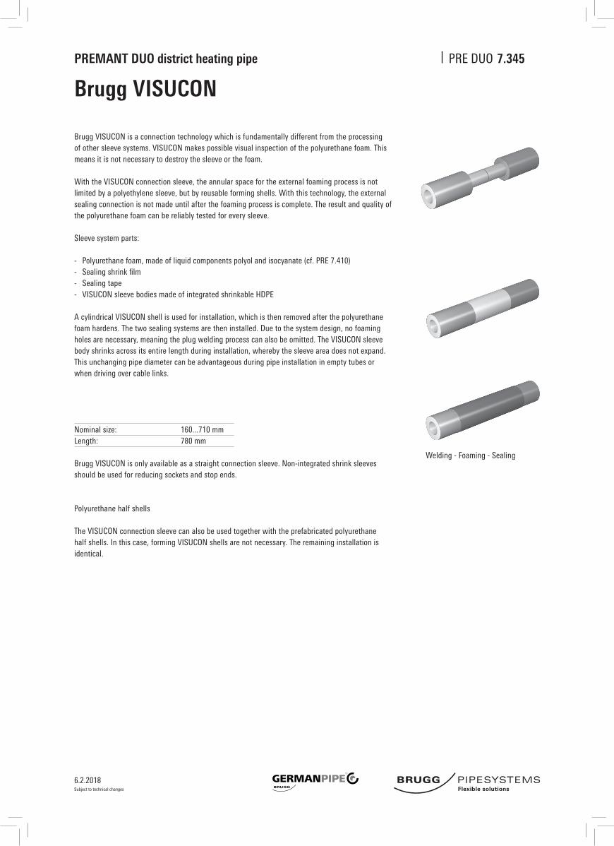
Brugg VISUCON
Brugg VISUCON is a connection technology which is fundamentally different from the processing of other sleeve systems. VISUCON makes possible visual inspection of the polyurethane foam. This means it is not necessary to destroy the sleeve or the foam.
With the VISUCON connection sleeve, the annular space for the external foaming process is not limited by a polyethylene sleeve, but by reusable forming shells. With this technology, the external sealing connection is not made until after the foaming process is complete. The result and quality of the polyurethane foam can be reliably tested for every sleeve.
Sleeve system parts:
- Polyurethane foam, made of liquid components polyol and isocyanate (cf. PRE 7.410)- Sealingshrinkfilm- Sealing tape- VISUCON sleeve bodies made of integrated shrinkable HDPE
A cylindrical VISUCON shell is used for installation, which is then removed after the polyurethane foam hardens. The two sealing systems are then installed. Due to the system design, no foaming holes are necessary, meaning the plug welding process can also be omitted. The VISUCON sleeve body shrinks across its entire length during installation, whereby the sleeve area does not expand.This unchanging pipe diameter can be advantageous during pipe installation in empty tubes or when driving over cable links.
Nominalsize: 160...710mmLength: 780 mm
Brugg VISUCON is only available as a straight connection sleeve. Non-integrated shrink sleeves should be used for reducing sockets and stop ends.
Polyurethane half shells
The VISUCON connection sleeve can also be used together with the prefabricated polyurethane half shells. In this case, forming VISUCON shells are not necessary. The remaining installation is identical.
Welding - Foaming - Sealing

6.2.2018
PREMANT DUO district heating pipe PRE DUO
Subject to technical changes
Pipe warning tape to be laid in the ground.
Standard roll length, 250 m
Installation depth; see sheet PRE 6.500
Wall sealing ring, pipe warning tape
Wall sealing ring
Pipe warning tape
Data table: sealing ring
D
90
110
125
140
160
180
200
225
250
315
355
400
450
500
560
630
710
Da
133
153
168
183
203
223
240
265
290
355
395
440
490
540
600
670
750
Figures in mm
50
Da
D
Material width Language Print colour
mm
40 German blue
100 German/English/French/Italian blue
7.355

6.2.2018
PREMANT DUO district heating pipe PRE DUO
Subject to technical changes
7.356
Shrink-on closure
Material:
Heat-shrunk,
cross-linkedpolyolefin.
Coated with
sealing adhesive
Important fitting note
PREMANT DUO shrink-on
closures must be pushed
onto the end of the
PREMANT DUO district
heating pipe before
welding the inner pipes,
and must be protected
against the action of heat
during welding.
Allocation of PREMANT DUO dimensions to type of shrink-on closure
min. 120 mm
Shrink-on closure/end cap
PREMANT DUO shrink-on closures protect the PUR insulation on the front of the PREMANT district heating pipes against splashingwaterinbuildingsandshafts.Theshrink-onclosureisnotnecessarilywatertightincontactwithwater(flood-ing). The shrink-on closure also stops gas escaping from the PUR insulation at the end of the pipe.
Nominal
width
DN
20- 20
25- 25
32- 32
40- 40
50- 50
65- 65
80- 80
100-100
125-125
150-150
200-200
Insulation thickness, DS1
Casing
pipe
mm
125
140
160
160
200
225
250
315
400
450
560
End cap
Type
2-30
2-30
2-70
2-70
2-90
2-90
D-110
D-120
D-130
D-140
D-355
Insulation thickness, DS2
Mantel-
rohr
mm
140
160
180
180
225
250
280
355
450
500
630
End cap
Type
2-50
2-60
2-70
2-70
2-90
D-110
D-120
D-130
D-140
D-140
D-355
Insulation thickness, DS3
Casing
pipe
mm
160
180
200
200
250
280
315
400
500
560
710
End cap
Type
2-50
2-60
2-70
2-70
2-110
D-120
D-120
D-130
D-140
D-355
D-355

6.2.2018
PREMANT DUO district heating pipe PRE DUO
Subject to technical changes
Rigid foam bar
Rigid foam bars are used as supports for plastic casing pipes in the pipe trench. Rigid foam bars can remain sanded into the pipe trench.
Rigid foam bars are only partially suitable for large pipes. They tend to break under high loads if they are not properly supported.Inmostcases,theadditionaloutlayforaflattrenchfloorisnotjustified.ForPREMANTDUOdistrictpipefromDN 100 upwards, GERMAN PIPE recommends sandbags, sand beds or timber strips.
If timber strips are used for alignment, it must be ensured that they are removed again after the welding work is com-pleted, prior to sanding-in. Otherwise, the casing may be damaged due to thermal expansion.
Nominal size Thickness Length
1 100 x 100 mm 1000 mm
Properties Value Unit
Material Polystyrene
Pressure resistance 150 kPa
Apparent (bulk) density 30 kg/m3
Thermal conductivity group 040
7.357

6.2.2018
PREMANT DUO district heating pipe PRE DUO
Subject to technical changes
7.360
Ring sealSeal against water (exerting pressure/not exerting pressure) in water-impermeable components
Wall leadthrough with double seal,impermeable to water exerting pressure
Wall leadthrough, impermeable to water not exerting pressure
Casing pipe diameter
PE
Ø R
mm
125, 140
160, 180
200, 225
250, 280
315
355
400
450
500
560
630
710
Liner pipe
Core bore
Ø D
mm
200
250
300
350
400
450
500
600
700
700
800
800
1 PREMANT DUO district heating pipe 2 Sealing kit, single seal 3 Linerpipemadeoffibrecementorcoatedcorebore
Installation / trench infillTo avoid deformations at the sealing point, it is especially important duringinstallationandwhenfillingthetrenchtoensurethatnosubse-quent sinking of the pipe can occur. We also recommend that the pipe is supported or suspended inside the building. Tightness cannot be guaranteed unless these recommendations are followed.
DR
1
2
3
R RD D
1 PREMANT DUO district heating pipe2 Sealing kit, double seal3 Linerpipemadeoffibrecementorcoatedcorebore
Core boresPerfect bores are required for installation. As hairline cracks may be present in the concrete or could be caused by processing, it is advisable to seal the entire length of the borehole wall with suitable sealant (such as AQUAGARD).
Tightness can only be guaranteed if this recommendation is fol-lowed.
1
2
3

6.2.2018
PREMANT DUO district heating pipe PRE DUO
Subject to technical changes
7.365
Expansion pad
DescriptionIn order to absorb expansion movements of the underground pipe system in bends, branches and reduction pieces, expansion pads must be applied to the outer PE casing in these areas. Expansion pads are manufactured from cross-linked closed-cell polyethylene, are permanently elastic,donotdecayandareresistanttochemicals.Theexpansionzoneisdesignedonthebasisofpipestaticscalculations.
DeliveryThedeliveryscopeforanexpansionzoneof1mcomprises2piecesofexpansionpadstrip,length1000mm,whicharegluedontotheoutercasingatthe3o'clockand9o'clockpositions.Laminateisthenwrappedaroundtheentirezoneinordertopreventsandorsoilparticlesfrompenetrating between the expansion pad and the PE casing.
Material: Polyethylene particle foam
Nominal width: SizeI 120mm SizeII 240mm SizeIII 360mm
Nominal thickness: 40 mm
Diameter
Outer casing
mm
125 to 160
180 to 280
315 to 355
400 to 450
500 to 560
630
710
Nominal size
Name
Size1
Size2
Size3
Size4
Size5
Size6
Size7
Existing
designation
I
II
III
II+II
II+ III
IIl+ III
IIl+ II+II
Weight
kg/unit
0.154
0.307
0.461
0.614
0.768
0.922
1.075
kg/m
0.307
0.614
0.922
1.229
1.536
1.843
2.151
Volume
m³/pce
0.0048
0.0096
0.0144
0.0192
0.0240
0.0288
0.0336
m³/m
0.0096
0.0192
0.0288
0.0384
0.0480
0.0576
0.0672
Properties
Apparent (bulk) density
Tensile strength
Compressive stress
50%deformationat23°C
Vibration fatigue test, 80,000 load changes
- Change in thickness
- Change in hardness number
Absorption of water (volume fraction)
- after 1d
- after 7d
Thermal conductivity at 10 °C
Value
32
160
100
2,4
2,4
2,0
3,0
0,040
Unit
Kg/m³
kPa
kPa
%
%
%
%
W/mK
1000
1000
1000
120 240 360
EP strip = 1 m
PUR insulation
Medium pipe
Laminate

6.2.2018
PREMANT DUO district heating pipe PRE DUO
Subject to technical changes
7.410
Assembly Foam
StorageThe components of the foam system may only be stored and transported in the original canisters. The canisters have to be stored in a dry environment. They should stay airtight closed and sealed. Direct solar radiation and frost have to be avoided.
Are the foam components stored in a closed room, the room has to be ventilated. The minimum ventilation is an air change twice in 24 h. The temperature ought to be between 10 and 25 ºC.
While storing together with other substances, these have to be basically compatible. Furthermore we refer to the “VCI-KonzeptzurZusammenlagerungvonChemikalien”ofthe“VerbandderchemischenIndustrie”.
PUR-foam-components should not be stored for longer then 6 months.
Characteristics Value Unit
Component A Polyol
Colour ocker
Density 1.04 kg/m3
Solubility in water yes
Component B Isocyanat
Colour brown
Density 1.23 kg/m3
Solubility in water no
DisposalBasicallyadisposalofthefluentcomponentsshouldbeavoided.Thedisposalofthisproducthattooccuratalltimesin compliance with the standards of environmental protection and laws of waste disposal as well as the requirements of the local authorities. It is recommended to clarify the details with the responsible waste management company.
Classification
Substance ADR/RID-class Water hazard class Storage class Waste class EAK Code
Component A (Polyol) 3 1 Class 3 08 04 09
Component B (Isocaynat) – 1 Class 10 08 05 01
Storage Value Unit
Temperature 10 ... 25 °C
Ventilation twice each 24 h
Period < 180 days