
Pre-alignment solutions applied to girders 1/19 Sylvain GRIFFET, 06/07/2010.
19
Pre-alignment solutions applied to girders 1/19 Sylvain GRIFFET, 06/07/2010
-
Upload
willa-ramsey -
Category
Documents
-
view
214 -
download
1
Transcript of Pre-alignment solutions applied to girders 1/19 Sylvain GRIFFET, 06/07/2010.
Pre-alignment solutions applied to girders
1/19Sylvain GRIFFET, 06/07/2010
2/19Sylvain GRIFFET, 06/07/2010
Plan
Our measurement systems (and associated uncertainties)
The measurement systems that we would like to test in the Lab
Loss of accuracy because of interfaces or holders
The different methods depending on what to measure
What we would like to add on the girders for the Lab
CONCLUSION
Pre-alignment solutions applied to girders

3/19Sylvain GRIFFET, 06/07/2010
Our measurement systems (and associated uncertainties)
This instrument follows a target type spherical prism (0.5''or 1.5'‘ usually) thanks to a tool of target recognition and engines.
Uncertainty around of 30μm in the case of a network of points put on a 2m long object.
Pre-alignment solutions applied to girders
Laser TrackerThe Laser Tracker is an opto-electronic instrument equipped with an interferometer, a high accuracy distance-meter and angular encoders (this is where the Laser Tracker is not so good).

4/19Sylvain GRIFFET, 06/07/2010
Our measurement systems (and associated uncertainties)
PhotogrammetryThe principle of photogrammetry is the analysis of photographic pictures taken from different points of view.
For example of the measurement of a 1.6m long accelerating structure.
Pre-alignment solutions applied to girders

5/19Sylvain GRIFFET, 06/07/2010
Our measurement systems (and associated uncertainties)
photogrammetryTargets, recognized by the software, are put on the object to be measured.
The scaling of the points network is done by measuring 6 points on 3 carbon rods (distance between two targets known with an accuracy better than 10µm). Sixty shots were needed to measure the 48 targets.
The uncertainty that can be expected on the determination of these 48 points around f 15μm.
Pre-alignment solutions applied to girders

6/19Sylvain GRIFFET, 06/07/2010
Our measurement systems (and associated uncertainties)
Micro-TriangulationThe principle of the Micro-Triangulation is to use the full potential of a theodolite by substituting a CCD camera instead of the eye of an operator. With a target recognition software, a ball or photogrammetric target for example, the angular precision sights on this target is of the order of 2.5μm per meter.
Pre-alignment solutions applied to girders
7/19Sylvain GRIFFET, 06/07/2010
Our measurement systems (and associated uncertainties)
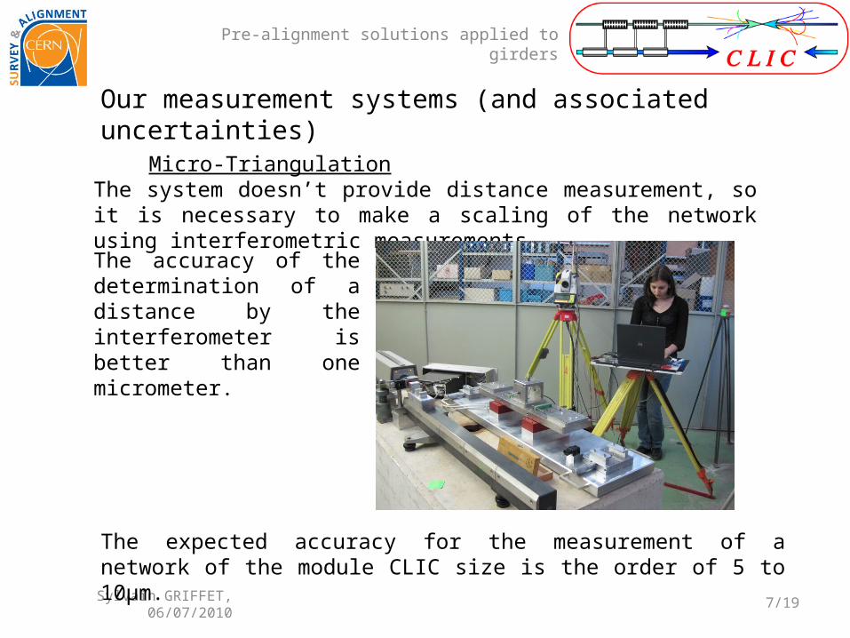
Micro-TriangulationThe system doesn’t provide distance measurement, so it is necessary to make a scaling of the network using interferometric measurements.
The expected accuracy for the measurement of a network of the module CLIC size is the order of 5 to 10µm.
Pre-alignment solutions applied to girders
The accuracy of the determination of a distance by the interferometer is better than one micrometer.

8/19Sylvain GRIFFET, 06/07/2010
The measurement systems that we would like to test in the Lab
New Laser Tracker Leica AT401The measurement principle and the distance-meter are the same as our Laser Tracker but this one uses the angular encoders of the most accurate Leica tacheometer.
The intrinsic accuracy of this system is ±15µm + 6µm per meter at 3σ.
Pre-alignment solutions applied to girders
9/19Sylvain GRIFFET, 06/07/2010
The measurement systems that we would like to test in the Lab
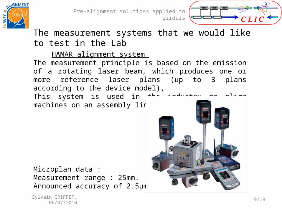
HAMAR alignment system The measurement principle is based on the emission of a rotating laser beam, which produces one or more reference laser plans (up to 3 plans according to the device model),This system is used in the industry to align machines on an assembly line for example.
Microplan data : Measurement range : 25mm.Announced accuracy of 2.5µm/m.
Pre-alignment solutions applied to girders

10/19Sylvain GRIFFET, 06/07/2010
The measurement systems that we would like to test in the Lab
Measuring armThis tool is a kind of portable CMM, measuring with a sensor; for example, the measuring arm Faro Quantum 1.2m:
"Measurement volume” of 2.4m, equipped with a sensor, 7 axes of rotation, carbon fiber skeleton, a temperature sensor at each joint, internal battery or mains connection, the model Quantum is the most accurate of the 3 Faro arm range.
Manufacturer's data:Repeatability tests on cone: 18μmAccuracy on length, maximum deviation: 25μm
Pre-alignment solutions applied to girders
11/19Sylvain GRIFFET, 06/07/2010
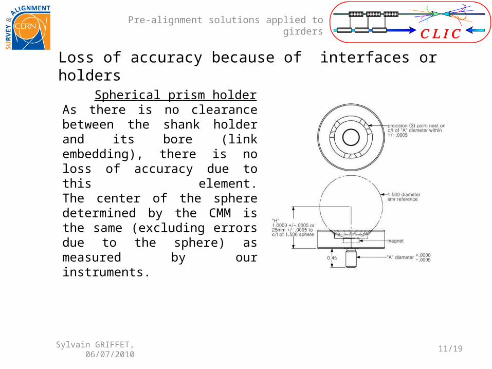
Loss of accuracy because of interfaces or holders
Spherical prism holderAs there is no clearance between the shank holder and its bore (link embedding), there is no loss of accuracy due to this element.The center of the sphere determined by the CMM is the same (excluding errors due to the sphere) as measured by our instruments.
Pre-alignment solutions applied to girders
12/19Sylvain GRIFFET, 06/07/2010
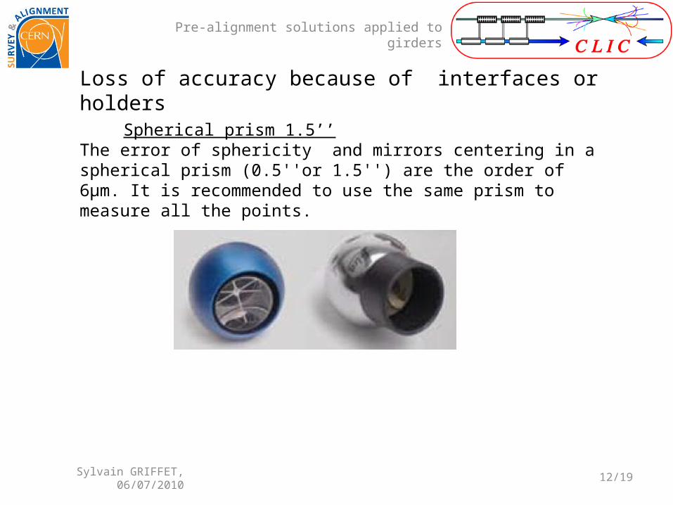
Loss of accuracy because of interfaces or holders
Spherical prism 1.5’’The error of sphericity and mirrors centering in a spherical prism (0.5''or 1.5'') are the order of 6μm. It is recommended to use the same prism to measure all the points.
Pre-alignment solutions applied to girders

13/19Sylvain GRIFFET, 06/07/2010
Loss of accuracy because of interfaces or holders
Ceramic or plastic ballsThe error of sphericity of this type of ball is less than the micrometer.
Pre-alignment solutions applied to girders
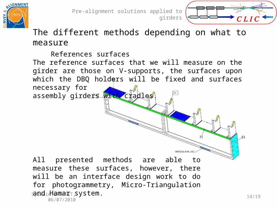
References surfacesThe reference surfaces that we will measure on the girder are those on V-supports, the surfaces upon which the DBQ holders will be fixed and surfaces necessary for assembly girders with cradles.
14/19Sylvain GRIFFET, 06/07/2010
The different methods depending on what to measure
All presented methods are able to measure these surfaces, however, there will be an interface design work to do for photogrammetry, Micro-Triangulation and Hamar system.
Pre-alignment solutions applied to girders

Sphere 1.5’’ holderThe holders on the cradles are provided to receive the spherical prisms 1.5’’. These prisms are measurable by the Laser Trackers, Micro-Triangulation and the measuring arm.
15/19Sylvain GRIFFET, 06/07/2010
The different methods depending on what to measure
Pre-alignment solutions applied to girders
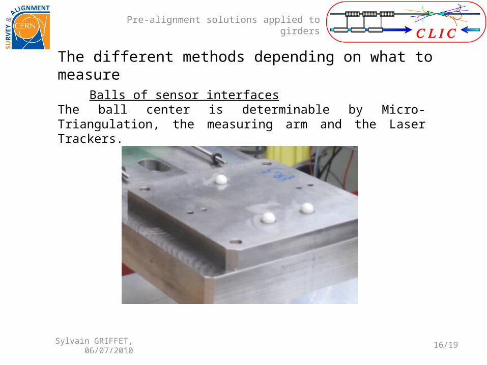
Balls of sensor interfacesThe ball center is determinable by Micro-Triangulation, the measuring arm and the Laser Trackers.
16/19Sylvain GRIFFET, 06/07/2010
The different methods depending on what to measure
Pre-alignment solutions applied to girders
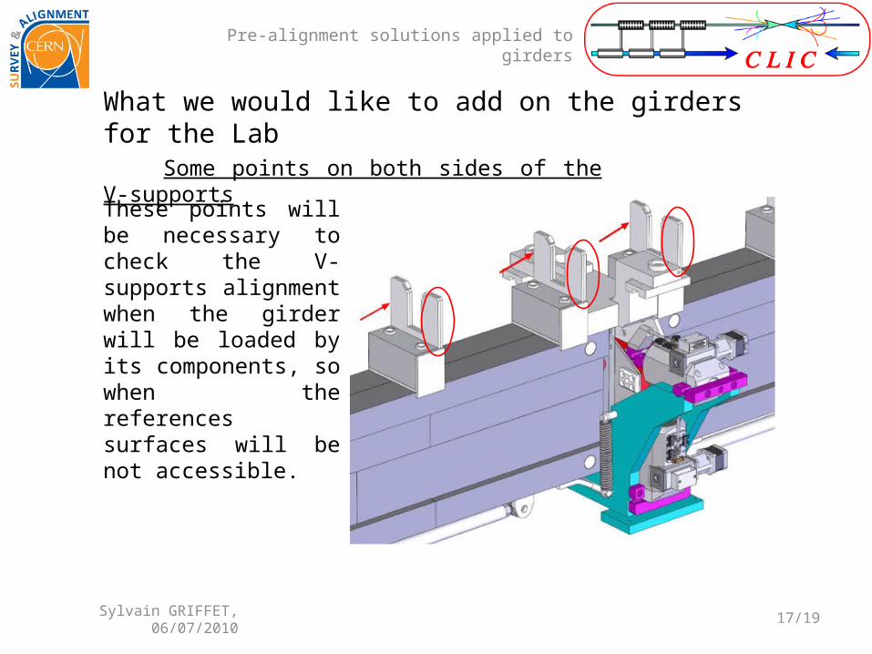
These points will be necessary to check the V-supports alignment when the girder will be loaded by its components, so when the references surfaces will be not accessible.
17/19Sylvain GRIFFET, 06/07/2010
What we would like to add on the girders for the Lab
Some points on both sides of the V-supports
Pre-alignment solutions applied to girders
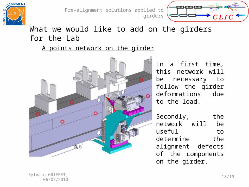
In a first time, this network will be necessary to follow the girder deformations due to the load.
Secondly, the network will be useful to determine the alignment defects of the components on the girder.
18/19Sylvain GRIFFET, 06/07/2010
What we would like to add on the girders for the Lab
A points network on the girder
Pre-alignment solutions applied to girders

19/19Sylvain GRIFFET, 06/07/2010
CONCLUSION
• We dispose of several tools, relatively accurate, useful without particular development.
• During the Lab test, we would like to test and validates alternative methods.
• The procedures for connecting the different coordinate systems remain to be defined (to move from beam system to the V-supports system, to move from the V-supports system to the girder system….).
• It is necessary to collaborate with Ahmed CHERIF to define some points accurately measurable by the CMM and by our methods.
Pre-alignment solutions applied to girders