Practicals & Tutorials workbook DC Machines... · 2019-03-04 · Practicals & Tutorials ......
63
Unit of competency UEENEEG101A PHILIPS RESOURCE PM. FINAL ver.1.1 27/01/2016 Updated Jan 2016 20222 Certificate III Electro-technology Electrician DC MACHINES Practicals & Tutorials PHILIPS UEENEEG101A Solve problems in electromagnetic devices and related circuits Subject Purpose: This unit covers determining correct operation of electromagnetic devices and related circuits and providing solutions as they apply to electrical installations and equipment. It encompasses working safely, power circuit problems solving processes, including the use of voltage, current and resistance measuring devices, providing solutions derived from measurements and calculations to predictable problems in electromagnetic devices and related circuits. STUDENT NAME___________________________________ DATE____________ TEACHER_______________________________________ CLASS ____________ Disclaimer: Printed copies of this document are regarded as uncontrolled. Please check \\Umfres1\electricaltrade\delevery resources\peterphilipsresouces\dcmachines. to ensure this is the latest version 1
Transcript of Practicals & Tutorials workbook DC Machines... · 2019-03-04 · Practicals & Tutorials ......
Unit of competency UEENEEG101A PHILIPS RESOURCE PM. FINAL ver.1.1 27/01/2016
Updated Jan 2016
20222 Certificate III
Electro-technology Electrician
DC MACHINES
Practicals & Tutorials
PHILIPS
UEENEEG101A Solve problems in electromagnetic devices and related circuits
Subject Purpose: This unit covers determining correct operation of electromagnetic devices and related circuits and providing solutions as they apply to electrical installations and equipment. It encompasses working safely, power circuit problems solving processes, including the use of voltage, current and resistance measuring devices, providing solutions derived from measurements and calculations to predictable problems in electromagnetic devices and related circuits.
STUDENT NAME___________________________________ DATE____________ TEACHER_______________________________________ CLASS ____________
Disclaimer: Printed copies of this document are regarded as uncontrolled. Please check \\Umfres1\electricaltrade\delevery resources\peterphilipsresouces\dcmachines. to ensure this is the latest version
1
Unit of competency UEENEEG101A PHILIPS RESOURCE PM. FINAL ver.1.1 27/01/2016
Duration: DC MACHINES 32 hours
LESSON STRUCTURE
Lesson Duration Topic Practicals Tutorials
1 4 hours The DC Generator Operating Principles &
Construction
DEMO Tutorial 1A The DC Generator
2 4 hours Separately Excited DC Generator
Practical 1 Separately Excited
Generator
Tutorial 1B Separately Excited
Generator
3 4 hours Self-Excited DC Generators
Practical 2 Self-Excited Generator
Tutorial 2 Self- Excited
Generator
4 4 hours The DC Motor Introduction & operating
Principles
Practical 3 DC Motor
Separately Excited
Tutorial 3 The DC Motor
5 4 hours DC Motor Types Series, Shunt, Compound
Practical 4 DC Motor
Characteristics & Reversal
Tutorial 4 DC Motor
Characteristics
6 4 hours Losses & Efficiency Starting Resistance
Reversing & Armature Reaction
Practical 5 DC Motor Starting
Tutorial 5 Starting &
Specialised Motors
7 4 hours Other types of DC motors & Revision
Revision of previous practicals
DC Generation & Motors-Revision
Chapter 13-14
8 4 hours Theory Test 2 Practical Test 2 MUST PASS
Assessment Component No.
Type of Assessment Duration Weighting %
1 Theory Test 1 2 hour 30 40
2 Practical Test 1 45 min. 10 10
3 Theory Test 2 2 hours 40 40
4 Practical Test 2 45 min. 10 10
5 Quizzes, Assignments, Tutorials. (optional at teachers discretion)
10 0
Total 100 100
2
Unit of competency UEENEEG101A PHILIPS RESOURCE PM. FINAL ver.1.1 27/01/2016
Contents
TOPIC Pages
The DC Generator Tutorial 1A 4-7
The separately Excited Generator Practical 1 8-14
The DC Generator Tutorial 1B 15-18
Self-Excited Generators Practical 2 19-24
Self-Excited Generators Tutorial 2 25-28
The DC Motor Separately Excited Practical 3 29-33
The DC Motor Tutorial 3 34-38
DC Motor Characteristics & Reversal Practical 4 39-46
DC Motor Characteristics Tutorial 4 47-50
DC Motor Starting Practical 5 51-54
Starting & Specialized Motors Tutorial 5 55-57
Chapter 13 DC Generators Chapter Tutorial 58-59
Chapter 14 DC Motors Chapter Tutorial 60-61
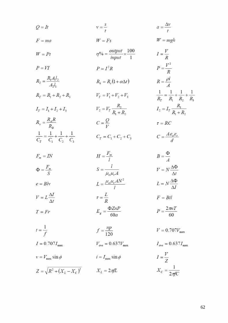
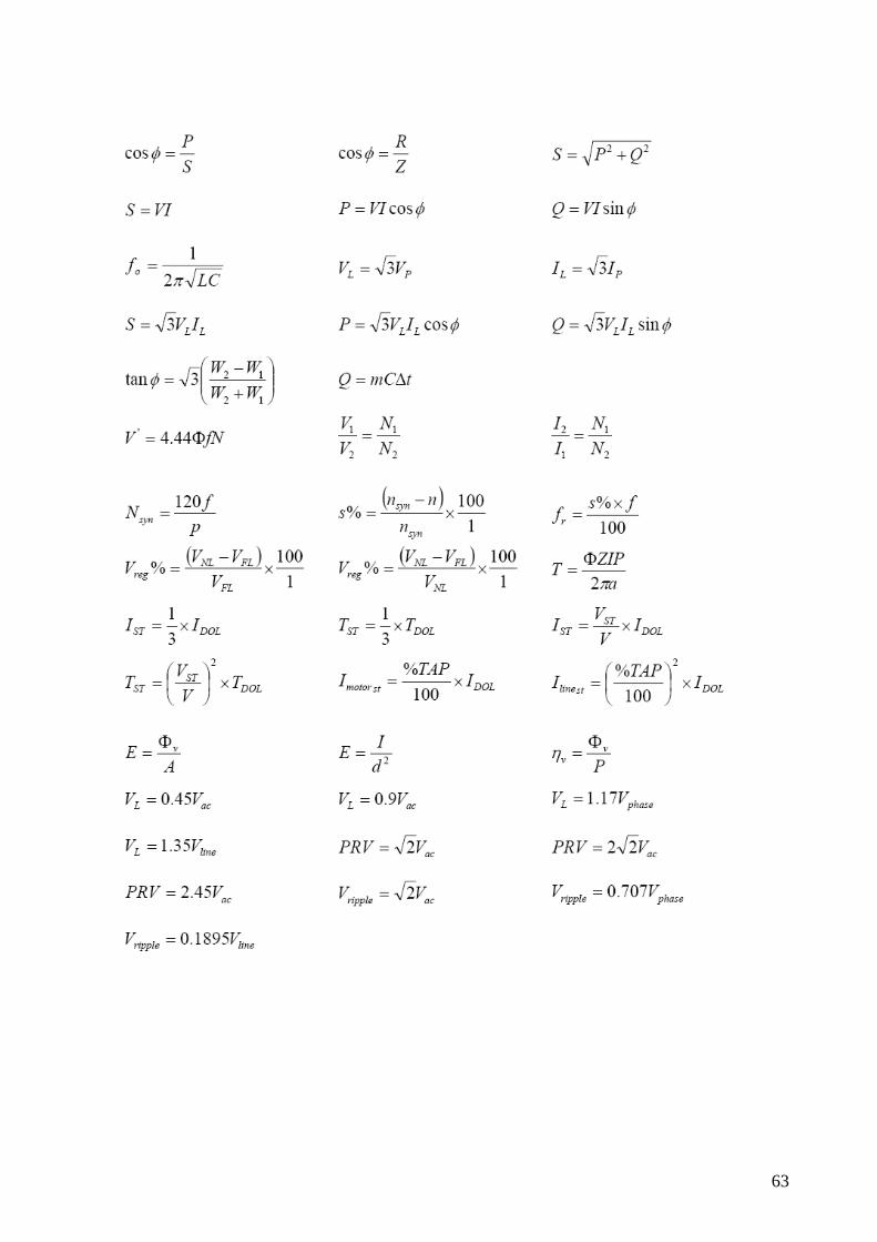
Formula Sheets 62-63
3
Unit of competency UEENEEG101A PHILIPS RESOURCE PM. FINAL ver.1.1 27/01/2016 Tutorial-1A (Philips, 270-277)
THE DC GENERATOR SECTION A Multiple Choice In the following statements one of the suggested answers is best. Place the identifying letter of your choice on your answer sheet.
1. A DC generator converts______________energy to______________energy.
a) electrical, mechanical b) electrical, electrical c) chemical, electrical d) mechanical, electrical
2. The principle by which emfs are generated in a DC generator is:
a) electromagnetic induction. b) Lenz's law. c) self inductance. d) chemical reaction.
3. The function of the commutator in a DC generator is to:
a) connect the AC generated in the windings directly to an external circuit. b) convert the AC generated in the windings to DC when connecting to an external circuit. c) supply an external current to the armature to drive the generator. d) allow the generator to be converted to a motor.
4. The main field windings are mounted on the:
a) armature. b) commutator. c) end plate. d) pole core
5. The value of the generated emfs in the armature conductors is_____________to the field flux,
and ___________ to the armature speed.
a) proportional, proportional b) proportional, inversely proportional c) inversely proportional, proportional d) inversely proportional, inversely proportional
6. The relationship between current, magnetic flux and the force applied to a conductor within a
generator can be determined by:
a) Fleming's right hand rule. b) Fleming's left hand rule. c) Faraday's right hand rule. d) Faraday's left hand rule.
4

Unit of competency UEENEEG101A PHILIPS RESOURCE PM. FINAL ver.1.1 27/01/2016 SECTION B Short Answer For the following questions, complete the statements on your answer sheet with the word or phrase you think fits best.
1. To connect the generated emfs to an external circuit, a ________________ and carbon _____________ are employed.
2. The function of the _________________ is to convert the _______________ voltage generated within the armature conductors to the_______________ voltage available at the generator terminals.
3. To determine the polarity of the induced emfs within the armature conductors you would use _______________________________.
4. Maximum emf will be induced in the armature ___________________ when cutting the field flux at_________________________.
5. If more turns are added to the armature conductors, the generated voltage will___________________________.
6. The emf induced into a conductor is proportional to the ________________________ of the magnetic field, the _____________________ of the conductor and the__________________________of the conductor through the magnetic field.
SECTION C Calculations
1. A single conductor of 150mm length is rotated through a field flux of 0.8T at a velocity of 10m/s. Determine the emf induced in the conductor. (1.2V)
5
Unit of competency UEENEEG101A PHILIPS RESOURCE PM. FINAL ver.1.1 27/01/2016
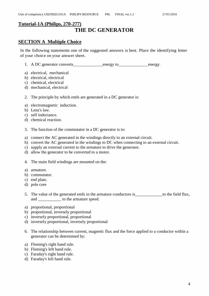
2. Determine the flux density of the magnetic field required to generate 12.6V in a conductor with an effective length of 2m which moves through the magnetic field with a uniform velocity of 10.5m/s. (0.6T)
3. A generator is wound with 6 series connected coils, each wound with 40 turns. If the length of the armature is 200mm, the density of the flux is 1.25 Tesla and the armature rotates with a velocity of 2m/s, determine the generated output voltage of the generator. (240V)
Section D Diagrams.
1. For the diagram of figure 1, label the following: the frame the field coil the armature the field pole
6
Unit of competency UEENEEG101A PHILIPS RESOURCE PM. FINAL ver.1.1 27/01/2016
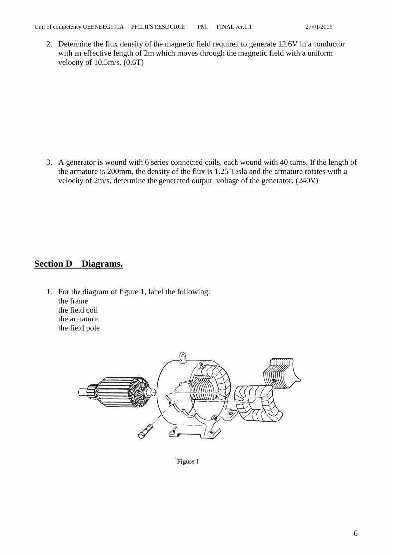
2. For the diagrams of figure 2(a) to 2(e), determine the direction of current flow through the conductors "a" and "b", and show the currents on the diagrams.
3. On the axis of figure 3, neatly draw the output waveform if the generated emf is connected to an external circuit via a commutator and brushes.
7
Unit of competency UEENEEG101A PHILIPS RESOURCE PM. FINAL ver.1.1 27/01/2016 Practical 1
THE SEPARATELY EXCITED GENERATOR PURPOSE: This practical assignment will be used to examine the no-load and load characteristics of the separately excited de generator. TO ACHIEVE THE PURPOSE OF THIS SECTION: At the end of this practical assignment the student will be able to: Connect a separately excited generator using a circuit diagram as a guide Carry out a no-load test on a de generator and plot the no-load characteristic. Carry out a load test on a de generator and plot the load characteristic. Using test results, draw the equivalent circuit of the armature circuit of a de generator. EQUIPMENT:
1 x variable DC power supply 1 x three phase 41.5/24V, 50Hz supply 1 x Betts DC compound machine 1 x Betts three phase, squirrel cage induction motor 1 x Betts Plate 1 x variable speed AC drive 1 x digital multimeter 2 x 0-2A analogue DC ammeter 1 x optical tachometer 4 x Lamps 4mm connecting leads
REMEMBER· WORK SAFELY AT ALL TIMES
Observe correct isolation procedures
8
Unit of competency UEENEEG101A PHILIPS RESOURCE PM. FINAL ver.1.1 27/01/2016
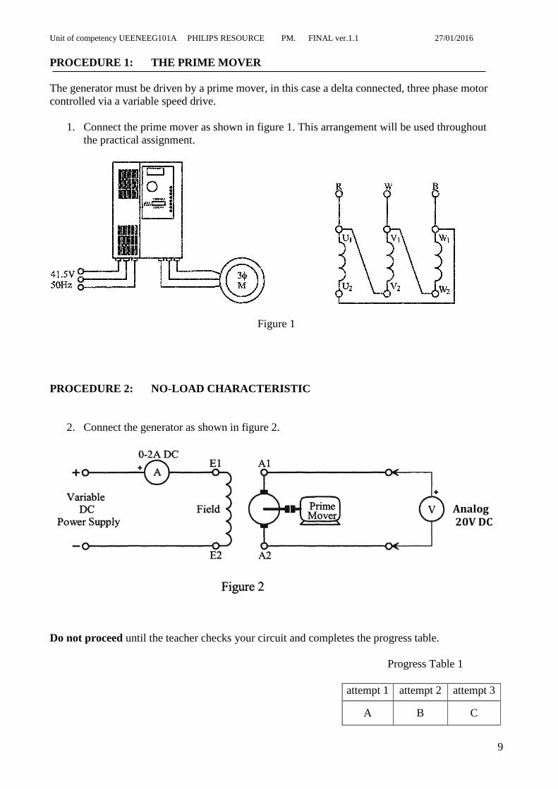
PROCEDURE 1: THE PRIME MOVER The generator must be driven by a prime mover, in this case a delta connected, three phase motor controlled via a variable speed drive.
1. Connect the prime mover as shown in figure 1. This arrangement will be used throughout the practical assignment.
Figure 1 PROCEDURE 2: NO-LOAD CHARACTERISTIC
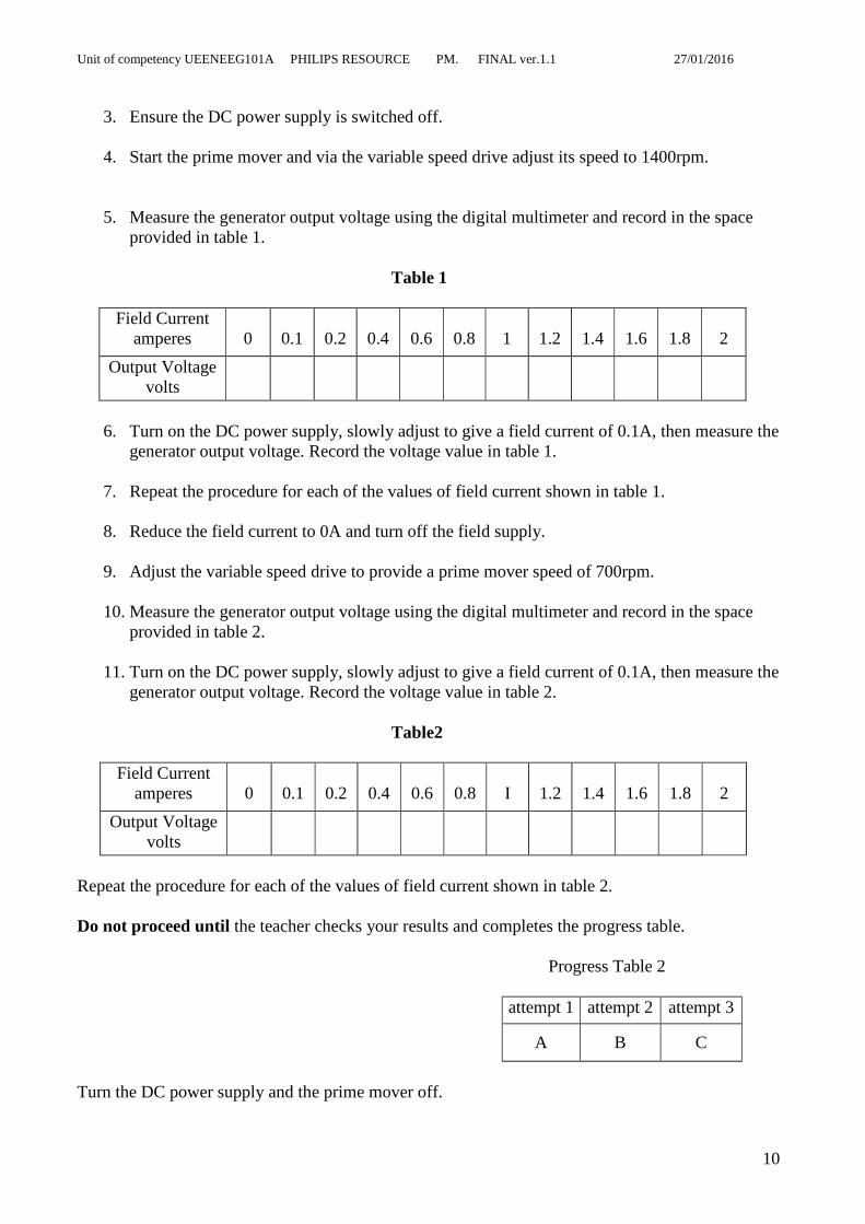
2. Connect the generator as shown in figure 2.
Do not proceed until the teacher checks your circuit and completes the progress table.
Progress Table 1
attempt 1 attempt 2 attempt 3
A B C
Analog 20V DC
9
Unit of competency UEENEEG101A PHILIPS RESOURCE PM. FINAL ver.1.1 27/01/2016
3. Ensure the DC power supply is switched off.
4. Start the prime mover and via the variable speed drive adjust its speed to 1400rpm.
5. Measure the generator output voltage using the digital multimeter and record in the space provided in table 1.
Table 1
Field Current
amperes 0
0.1
0.2
0.4
0.6
0.8
1
1.2
1.4
1.6
1.8
2
Output Voltage volts
6. Turn on the DC power supply, slowly adjust to give a field current of 0.1A, then measure the
generator output voltage. Record the voltage value in table 1.
7. Repeat the procedure for each of the values of field current shown in table 1.
8. Reduce the field current to 0A and turn off the field supply.
9. Adjust the variable speed drive to provide a prime mover speed of 700rpm.
10. Measure the generator output voltage using the digital multimeter and record in the space provided in table 2.
11. Turn on the DC power supply, slowly adjust to give a field current of 0.1A, then measure the
generator output voltage. Record the voltage value in table 2.
Table2
Field Current amperes
0
0.1
0.2
0.4
0.6
0.8
I
1.2
1.4
1.6
1.8
2
Output Voltage volts
Repeat the procedure for each of the values of field current shown in table 2. Do not proceed until the teacher checks your results and completes the progress table.
Progress Table 2
attempt 1 attempt 2 attempt 3
A B C
Turn the DC power supply and the prime mover off.
10
Unit of competency UEENEEG101A PHILIPS RESOURCE PM. FINAL ver.1.1 27/01/2016 PROCEDURE 3: LOAD CHARACTERISTIC
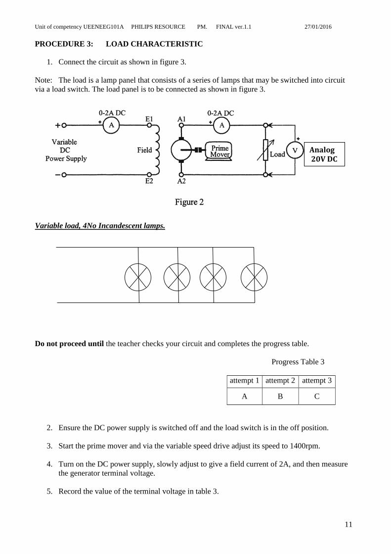
1. Connect the circuit as shown in figure 3. Note: The load is a lamp panel that consists of a series of lamps that may be switched into circuit via a load switch. The load panel is to be connected as shown in figure 3. Variable load, 4No Incandescent lamps. Do not proceed until the teacher checks your circuit and completes the progress table.
Progress Table 3
attempt 1 attempt 2 attempt 3
A B C
2. Ensure the DC power supply is switched off and the load switch is in the off position.
3. Start the prime mover and via the variable speed drive adjust its speed to 1400rpm.
4. Turn on the DC power supply, slowly adjust to give a field current of 2A, and then measure the generator terminal voltage.
5. Record the value of the terminal voltage in table 3.
Analog 20V DC
11
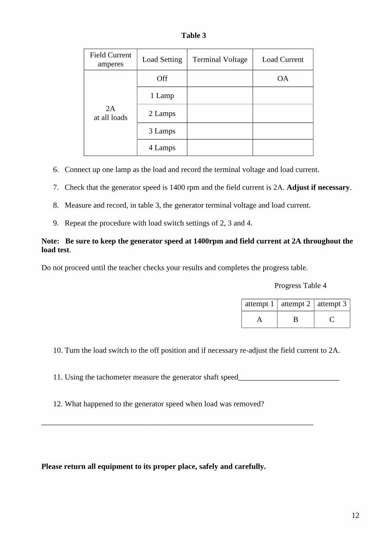
Table 3
Field Current amperes Load Setting Terminal Voltage Load Current
2A at all loads
Off OA
1 Lamp
2 Lamps
3 Lamps
4 Lamps
6. Connect up one lamp as the load and record the terminal voltage and load current.
7. Check that the generator speed is 1400 rpm and the field current is 2A. Adjust if necessary.
8. Measure and record, in table 3, the generator terminal voltage and load current.
9. Repeat the procedure with load switch settings of 2, 3 and 4.
Note: Be sure to keep the generator speed at 1400rpm and field current at 2A throughout the load test. Do not proceed until the teacher checks your results and completes the progress table.
Progress Table 4
attempt 1 attempt 2 attempt 3
A B C
10. Turn the load switch to the off position and if necessary re-adjust the field current to 2A.
11. Using the tachometer measure the generator shaft speed__________________________
12. What happened to the generator speed when load was removed? ______________________________________________________________________ Please return all equipment to its proper place, safely and carefully.
12

OBSERVATIONS: 1. using the axis of figure 4, draw the no-load characteristics of the generator at both 1400rpm and 700rpm. Output Voltage
Field Current
Figure 4
2. Based on your results, what is the relationship between generator speed and the generated
emf? ____________________________________________________________________________________________________________________________________________________ __________________________________________________________________________
3. Based on your results, what is the relationship between generated voltage and field current?
26
24
22
20
18
16
14
12
10
8
6
4
2
0
0 0.2 0.4 0.6 0.8 1 1.2 1.4 1.6 1.8 2.0
13

4. Using the axis of figure 5, draw the load characteristic for the generator? Generated Voltage
Load Current
Figure 5
5. What causes the terminal voltage of the generator to decrease with an increase of load? ______________________________________________________________________________________________________________________________________________________
6. Using the results obtained with maximum load on the generator; determine the resistance of the armature circuit.
7. What is the effect of increased generator load on the speed of the prime mover? ________________________________________________________________________________________________________________________________
26
24
22
20
18
16
14
12
10
8
6
4
2
0
0 0.2 0.4 0.6 0.8 1 1.2 1.4 1.6 1.8 2.0
14
Tutorial 1B (Philips, 278-284)
SEPARATELY EXCITED GENERATOR SECTION A Short Answer For the following questions, complete the statements on your answer sheet with the word or phrase you think fits best.
1. When the field current in a separately excited generator is zero, the output voltage is not zero due to________________________________
2. If the speed of the prime mover driving a generator is reduced, the output voltage wil1___________________
3. Increasing the load on a generator causes the prime mover speed to _________________ due to the __________________________ developed by the armature current.
4. Armature reaction will shift the ______________ axis in the _____________________ direction as the direction of rotation.
5. As the load on a generator increases, the effect of armature reaction __________________ , which results in the brushes being in the _______________ position for good commutation.
6. As the load on a generator increases, the concentration of flux on the trailing edge of the pole face_________________________, and the concentration of flux on the leading edge of the pole face ______________________.
7. As the load on a generator increases, the terminal voltage _______________ This is due to ________________ and the ___________________ voltage drop.
8. The terminal voltage of a generator is the ______________________________ between the generated voltage and the__________________________________ voltage drop.
9. The open circuit characteristic of a separately excited generator shows the _________________________________ of the magnetic material used in core.
15
SECTION B Calculations
1. A separately excited generator has an effective flux of 8mWb and is operated at a speed of 292 rpm. If the machine constant is 12, determine the:
a) generated voltage; (28V) b) no-load terminal voltage. (28V)
2. Determine the field flux required to produce a no-load voltage of 240V in a separately excited generator rotating at 600rpm with a machine constant of 15. (26.7mWb)
3. Determine the speed a prime mover must drive a generator under no load to produce a terminal voltage of 300V. The generator has an effective flux of 20mWb and a machine constant of 15. (1000rpm)
4. A generator has an armature resistance of 150mΩ and a full load resistance of 25Ω. If the open circuit voltage is 250V, determine the terminal voltage at full load. (248.5V)
16

5. A separately excited generator has an effective field flux of 20mWb, a machine constant of 12 and spins at 400 rpm. If the generator has an armature circuit resistance of 150mΩ and an armature current of 20A, determine the load voltage for this condition. (93V)
6. The generator shown in figure 1 has a machine constant of 10, and effective flux of 25mWb and is driven at 1000rpm, determine;
a) field current; (111mA) b) generated voltage; (250V) c) armature current; (16.54A) d) armature circuit voltage drop. (2V) e) terminal voltage (248V)
Figure 1
17
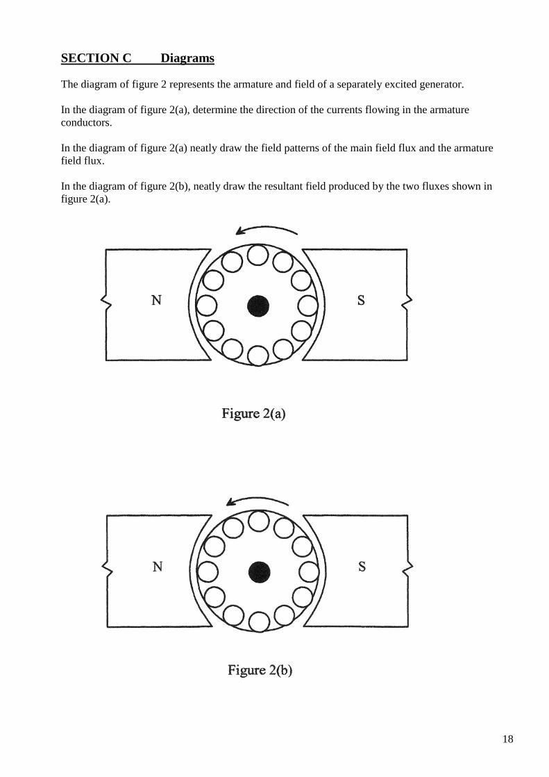
SECTION C Diagrams The diagram of figure 2 represents the armature and field of a separately excited generator. In the diagram of figure 2(a), determine the direction of the currents flowing in the armature conductors. In the diagram of figure 2(a) neatly draw the field patterns of the main field flux and the armature field flux. In the diagram of figure 2(b), neatly draw the resultant field produced by the two fluxes shown in figure 2(a).
18

Practical 2 (Philips, 285-296)SELF-EXCITED GENERATORS
PURPOSE: This practical assignment will be used to examine the load characteristics of the shunt and compound self-excited de generators. TO ACHIEVE THE PURPOSE OF THIS SECTION:
• At the end of this practical assignment the student will be able to: • Connect a shunt generator using a circuit diagram as a guide. • Carry out a load test on a shunt generator and plot the load characteristic. • Connect a compound generator using a circuit diagram as a guide. • Carry out a load test on a compound generator and plot the load characteristic. • Compare the performance of shunt and compound de generators.
EQUIPMENT:
1 x variable DC power supply 1 x Baldor DC compound machine 1 x Betts single phase, 230V Motor (prime mover) 1 x Betts machine plate 1 x digital multimeter 1 x 0-2A analogue DC ammeter 4 x Incandescent lamps (connect in parallel) 4mm connecting leads
REMEMBER- WORK SAFELY AT ALL TIMES· Observe correct isolation procedures
19
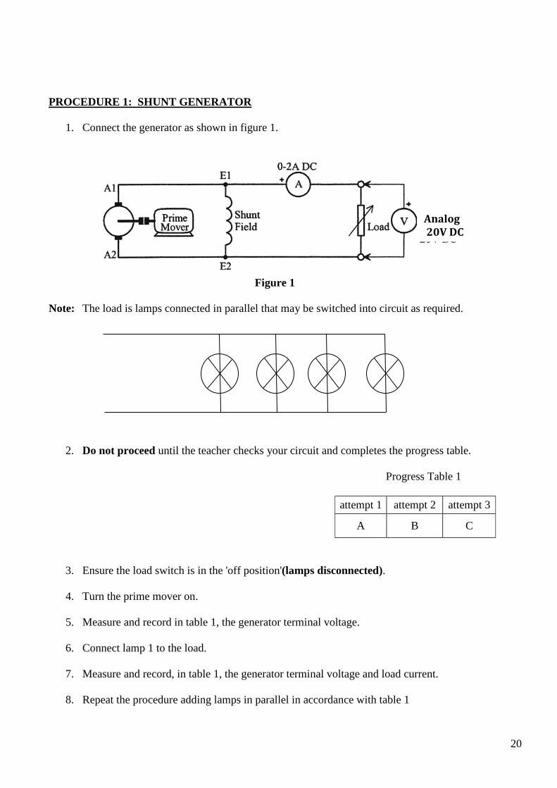
PROCEDURE 1: SHUNT GENERATOR
1. Connect the generator as shown in figure 1.
Figure 1 Note: The load is lamps connected in parallel that may be switched into circuit as required.
2. Do not proceed until the teacher checks your circuit and completes the progress table.
Progress Table 1
attempt 1 attempt 2 attempt 3
A B C
3. Ensure the load switch is in the 'off position'(lamps disconnected).
4. Turn the prime mover on.
5. Measure and record in table 1, the generator terminal voltage.
6. Connect lamp 1 to the load.
7. Measure and record, in table 1, the generator terminal voltage and load current.
8. Repeat the procedure adding lamps in parallel in accordance with table 1
Analog 20V DC
20
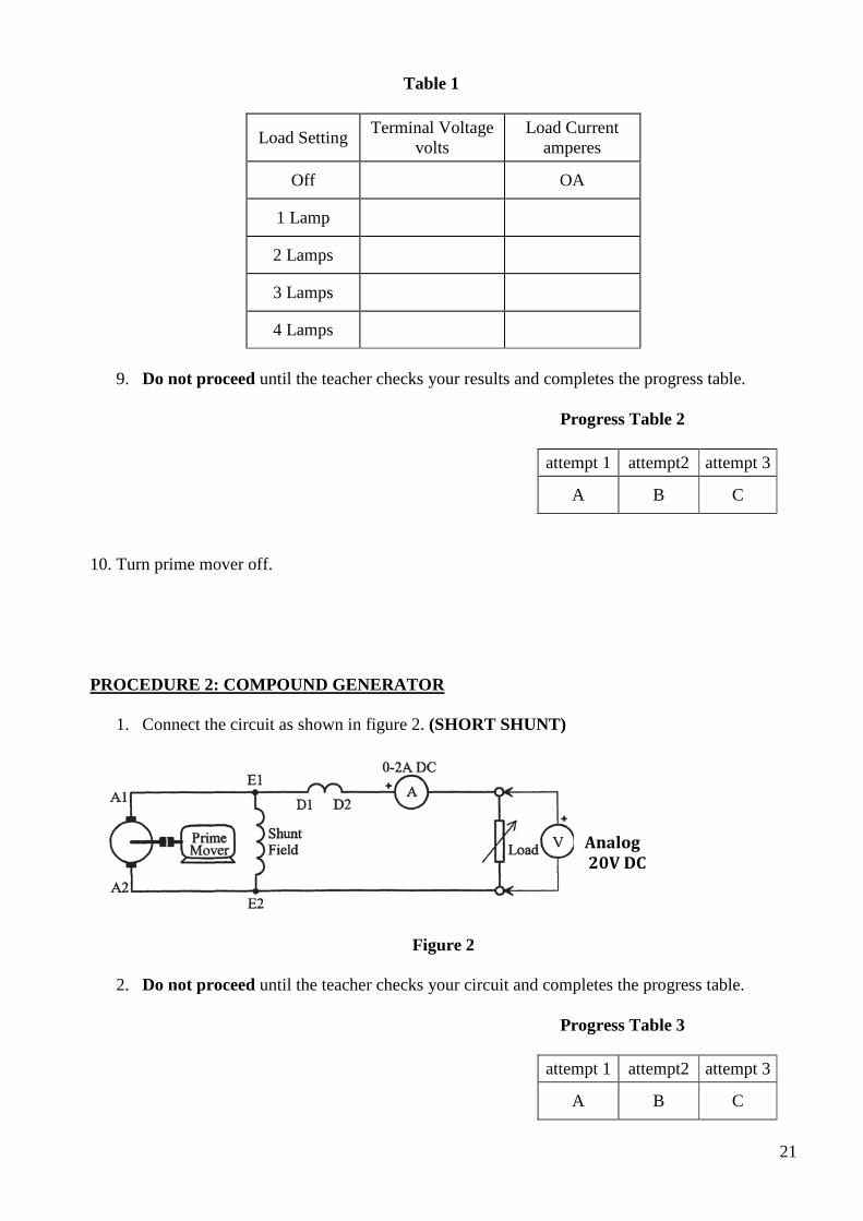
Table 1
Load Setting Terminal Voltage volts
Load Current amperes
Off OA
1 Lamp
2 Lamps
3 Lamps
4 Lamps
9. Do not proceed until the teacher checks your results and completes the progress table.
Progress Table 2
attempt 1 attempt2 attempt 3
A B C
10. Turn prime mover off. PROCEDURE 2: COMPOUND GENERATOR
1. Connect the circuit as shown in figure 2. (SHORT SHUNT)
Figure 2
2. Do not proceed until the teacher checks your circuit and completes the progress table.
Progress Table 3
attempt 1 attempt2 attempt 3
A B C
Analog 20V DC
21
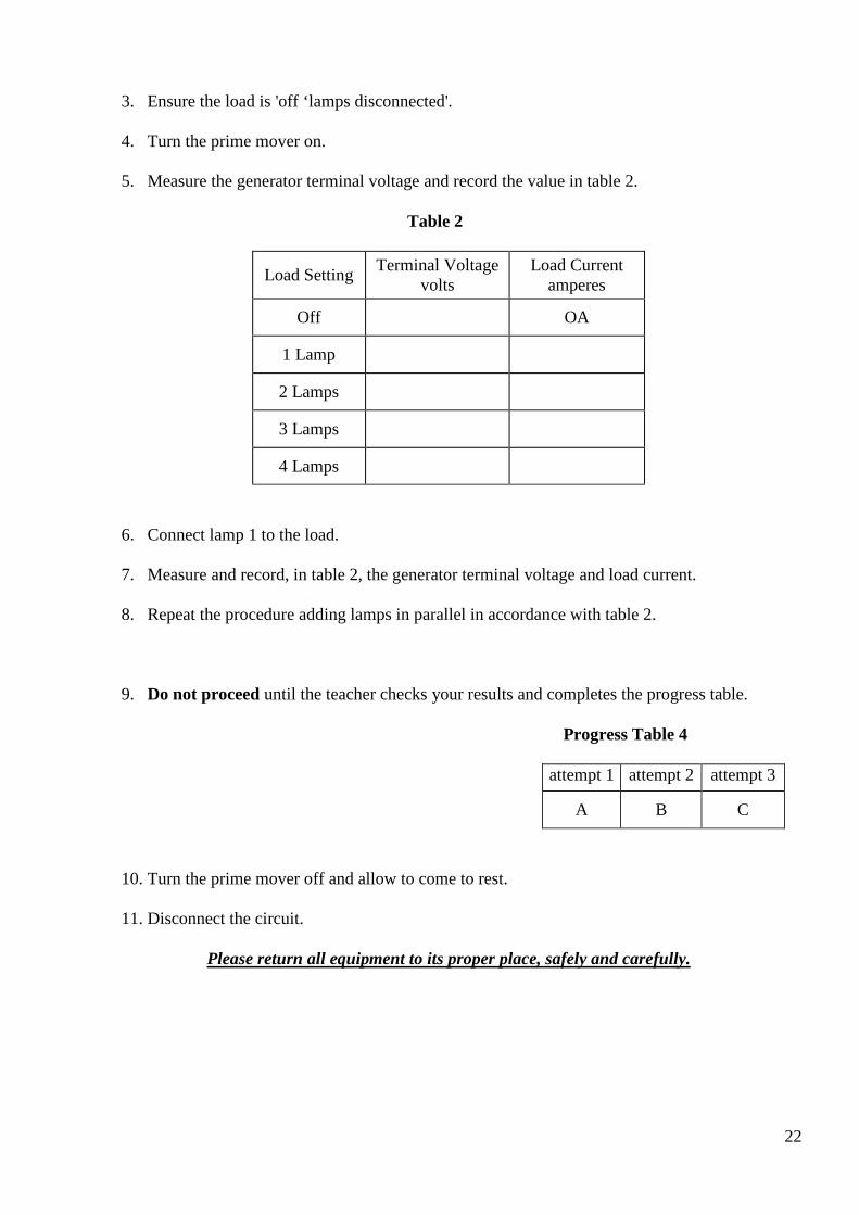
3. Ensure the load is 'off ‘lamps disconnected'.
4. Turn the prime mover on.
5. Measure the generator terminal voltage and record the value in table 2.
Table 2
Load Setting Terminal Voltage volts
Load Current amperes
Off OA
1 Lamp
2 Lamps
3 Lamps
4 Lamps
6. Connect lamp 1 to the load.
7. Measure and record, in table 2, the generator terminal voltage and load current.
8. Repeat the procedure adding lamps in parallel in accordance with table 2.
9. Do not proceed until the teacher checks your results and completes the progress table.
Progress Table 4
attempt 1 attempt 2 attempt 3
A B C
10. Turn the prime mover off and allow to come to rest.
11. Disconnect the circuit.
Please return all equipment to its proper place, safely and carefully.
22

-
,
OBSERVATIONS:
1. Using the axis of figure 3, draw the load characteristics for the shunt generator. OUTPUT VOLTAGE
Load Current
Figure 3
2. What are the factors that cause the terminal voltage of a shunt generator to decease with an
increase of load? ____________________________________________________________________________________________________________________________________________________________________________________________________________________________________________________________________________________________________________
3. Why is a shunt generator considered to be short circuit proof? Use your results to verify your
answer. _________________________________________________________________________________________________________________________________________________________________________________________________________________________________
4. Using the axis of figure 3, draw the load characteristic for the compound generator?
20
18
16
14
12
10
8
6
4
2
0
0 0.5 1.0 1.5 2.0 2.5 3.0 3.5 4.0
23

5. Why were the load characteristics for the compound generator better than those of the shunt
generator?
6. Of the two generators tested, which would be better for suppling a high current load?
7. What could have been done during construction, to improve the load characteristics of the compound generator?
24
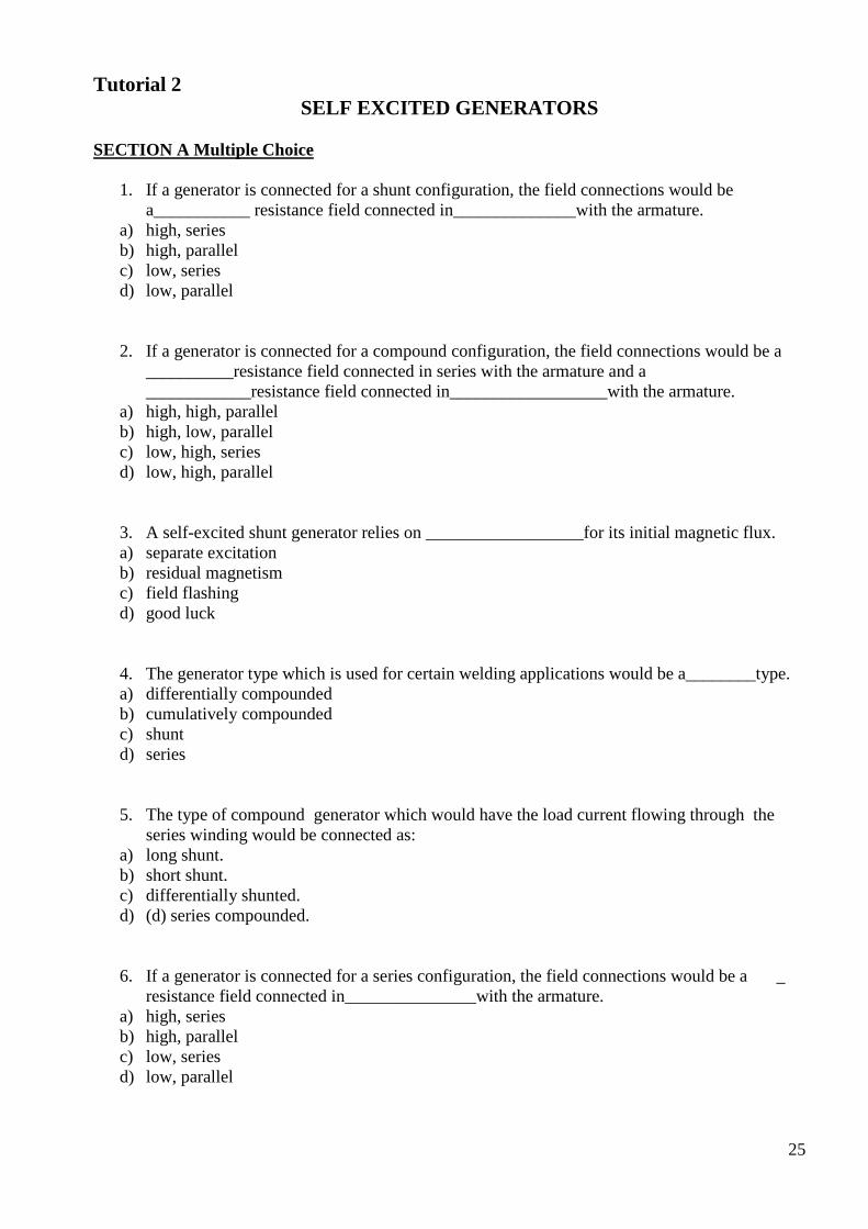
Tutorial 2 SELF EXCITED GENERATORS
SECTION A Multiple Choice
1. If a generator is connected for a shunt configuration, the field connections would be a___________ resistance field connected in______________with the armature.
a) high, series b) high, parallel c) low, series d) low, parallel
2. If a generator is connected for a compound configuration, the field connections would be a __________resistance field connected in series with the armature and a ____________resistance field connected in__________________with the armature.
a) high, high, parallel b) high, low, parallel c) low, high, series d) low, high, parallel
3. A self-excited shunt generator relies on __________________for its initial magnetic flux. a) separate excitation b) residual magnetism c) field flashing d) good luck
4. The generator type which is used for certain welding applications would be a________type. a) differentially compounded b) cumulatively compounded c) shunt d) series
5. The type of compound generator which would have the load current flowing through the series winding would be connected as:
a) long shunt. b) short shunt. c) differentially shunted. d) (d) series compounded.
6. If a generator is connected for a series configuration, the field connections would be a _ resistance field connected in_______________with the armature.
a) high, series b) high, parallel c) low, series d) low, parallel
25
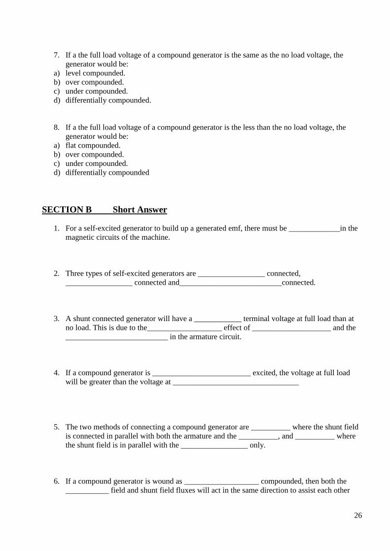
7. If a the full load voltage of a compound generator is the same as the no load voltage, the generator would be:
a) level compounded. b) over compounded. c) under compounded. d) differentially compounded.
8. If a the full load voltage of a compound generator is the less than the no load voltage, the generator would be:
a) flat compounded. b) over compounded. c) under compounded. d) differentially compounded
SECTION B Short Answer
1. For a self-excited generator to build up a generated emf, there must be _____________in the magnetic circuits of the machine.
2. Three types of self-excited generators are _________________ connected, _________________ connected and__________________________connected.
3. A shunt connected generator will have a ____________ terminal voltage at full load than at no load. This is due to the___________________ effect of ____________________ and the __________________________ in the armature circuit.
4. If a compound generator is _________________________ excited, the voltage at full load will be greater than the voltage at ________________________________
5. The two methods of connecting a compound generator are __________ where the shunt field is connected in parallel with both the armature and the __________, and __________ where the shunt field is in parallel with the _________________ only.
6. If a compound generator is wound as ___________________ compounded, then both the ___________ field and shunt field fluxes will act in the same direction to assist each other
26
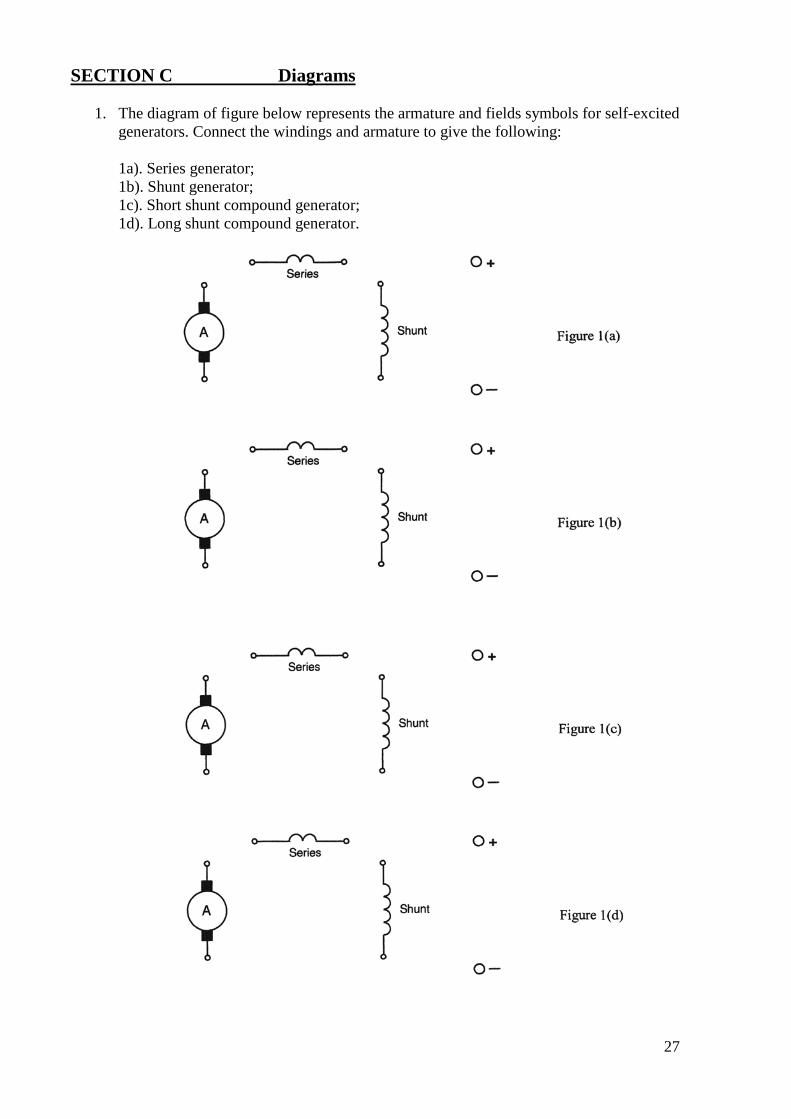
SECTION C Diagrams
1. The diagram of figure below represents the armature and fields symbols for self-excited generators. Connect the windings and armature to give the following:
1a). Series generator; 1b). Shunt generator; 1c). Short shunt compound generator; 1d). Long shunt compound generator.
27
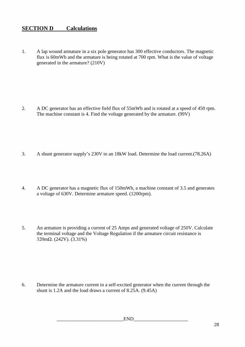
SECTION D Calculations 1. A lap wound armature in a six pole generator has 300 effective conductors. The magnetic
flux is 60mWb and the armature is being rotated at 700 rpm. What is the value of voltage generated in the armature? (210V)
2. A DC generator has an effective field flux of 55mWb and is rotated at a speed of 450 rpm.
The machine constant is 4. Find the voltage generated by the armature. (99V) 3. A shunt generator supply’s 230V to an 18kW load. Determine the load current.(78.26A) 4. A DC generator has a magnetic flux of 150mWb, a machine constant of 3.5 and generates
a voltage of 630V. Determine armature speed. (1200rpm). 5. An armature is providing a current of 25 Amps and generated voltage of 250V. Calculate
the terminal voltage and the Voltage Regulation if the armature circuit resistance is 320mΩ. (242V). (3.31%)
6. Determine the armature current in a self-excited generator when the current through the
shunt is 1.2A and the load draws a current of 8.25A. (9.45A)
___________________________END______________________
28
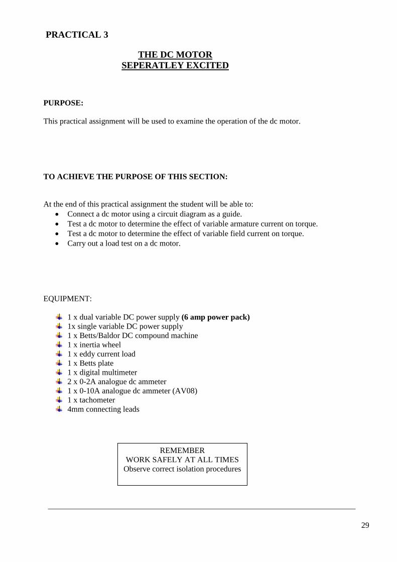
PRACTICAL 3
THE DC MOTOR SEPERATLEY EXCITED
PURPOSE:
This practical assignment will be used to examine the operation of the dc motor. TO ACHIEVE THE PURPOSE OF THIS SECTION: At the end of this practical assignment the student will be able to:
• Connect a dc motor using a circuit diagram as a guide. • Test a dc motor to determine the effect of variable armature current on torque. • Test a dc motor to determine the effect of variable field current on torque. • Carry out a load test on a dc motor.
EQUIPMENT:
1 x dual variable DC power supply (6 amp power pack) 1x single variable DC power supply 1 x Betts/Baldor DC compound machine 1 x inertia wheel 1 x eddy current load 1 x Betts plate 1 x digital multimeter 2 x 0-2A analogue dc ammeter 1 x 0-10A analogue dc ammeter (AV08) 1 x tachometer 4mm connecting leads
REMEMBER WORK SAFELY AT ALL TIMES
Observe correct isolation procedures
29
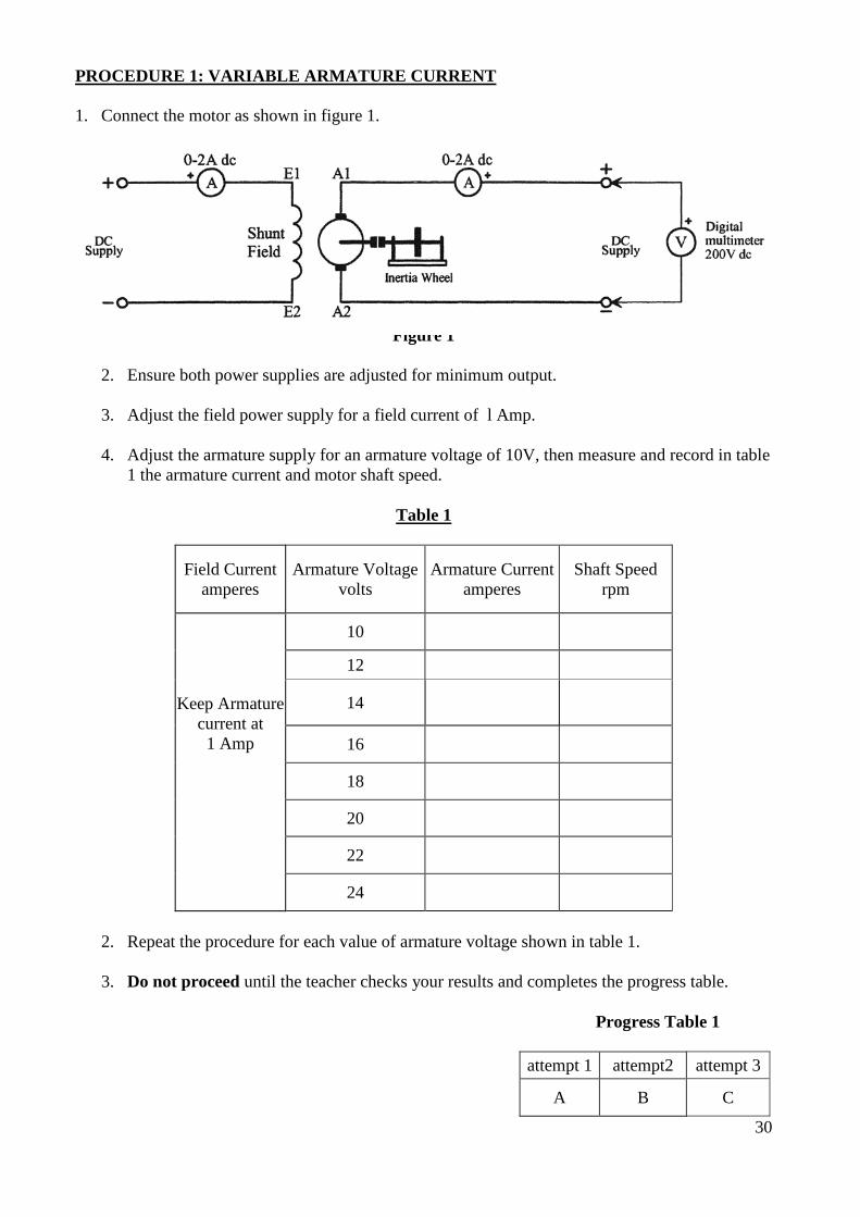
PROCEDURE 1: VARIABLE ARMATURE CURRENT 1. Connect the motor as shown in figure 1.
Figure 1
2. Ensure both power supplies are adjusted for minimum output.
3. Adjust the field power supply for a field current of l Amp.
4. Adjust the armature supply for an armature voltage of 10V, then measure and record in table 1 the armature current and motor shaft speed.
Table 1
Field Current amperes
Armature Voltage volts
Armature Current amperes
Shaft Speed rpm
Keep Armature current at
1 Amp
10
12
14
16
18
20
22
24
2. Repeat the procedure for each value of armature voltage shown in table 1.
3. Do not proceed until the teacher checks your results and completes the progress table.
Progress Table 1
attempt 1 attempt2 attempt 3
A B C
30
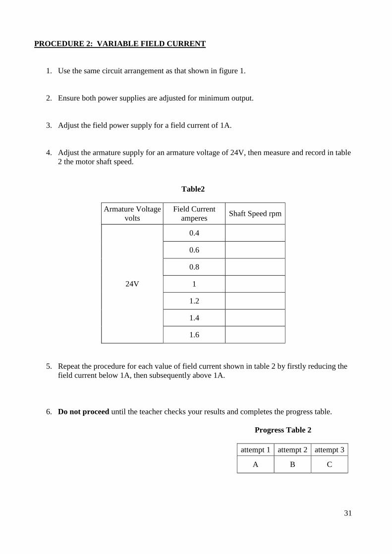
PROCEDURE 2: VARIABLE FIELD CURRENT
1. Use the same circuit arrangement as that shown in figure 1.
2. Ensure both power supplies are adjusted for minimum output.
3. Adjust the field power supply for a field current of 1A.
4. Adjust the armature supply for an armature voltage of 24V, then measure and record in table 2 the motor shaft speed.
Table2
Armature Voltage volts
Field Current amperes Shaft Speed rpm
24V
0.4
0.6
0.8
1
1.2
1.4
1.6
5. Repeat the procedure for each value of field current shown in table 2 by firstly reducing the field current below 1A, then subsequently above 1A.
6. Do not proceed until the teacher checks your results and completes the progress table.
Progress Table 2
attempt 1 attempt 2 attempt 3
A B C
31
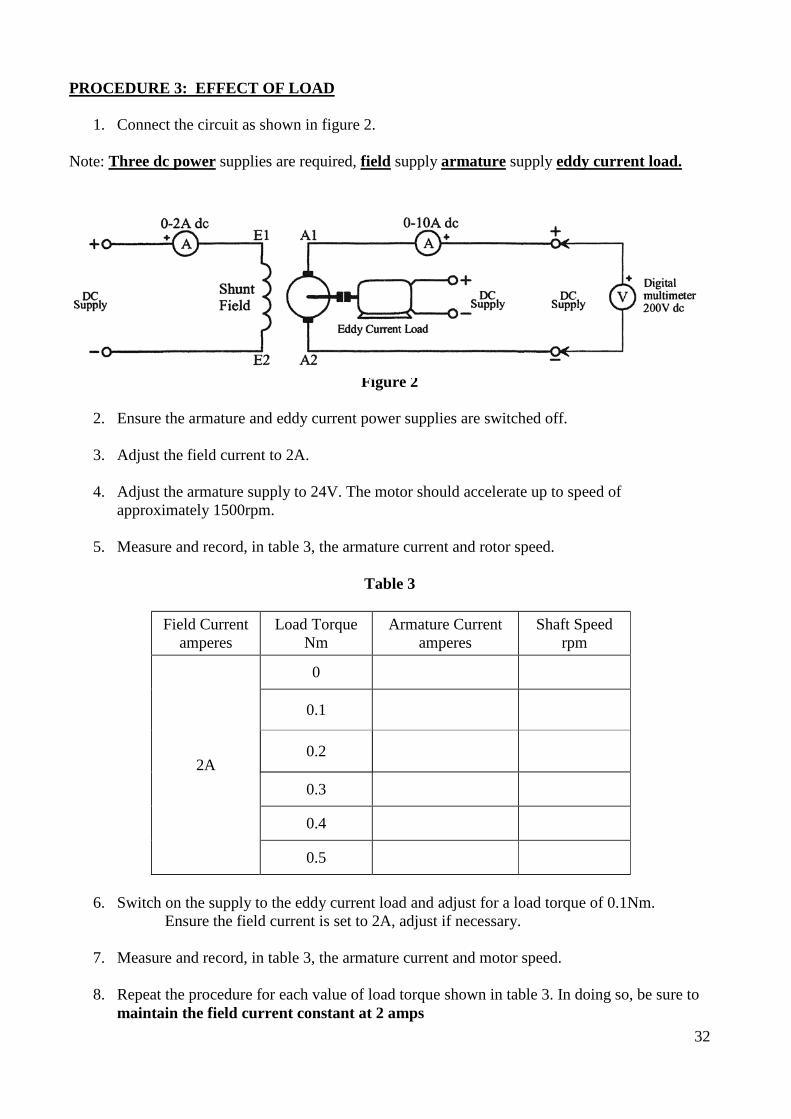
PROCEDURE 3: EFFECT OF LOAD
1. Connect the circuit as shown in figure 2.
Note: Three dc power supplies are required, field supply armature supply eddy current load.
Figure 2
2. Ensure the armature and eddy current power supplies are switched off.
3. Adjust the field current to 2A.
4. Adjust the armature supply to 24V. The motor should accelerate up to speed of approximately 1500rpm.
5. Measure and record, in table 3, the armature current and rotor speed.
Table 3
Field Current
amperes Load Torque
Nm Armature Current
amperes Shaft Speed
rpm
2A
0
0.1
0.2
0.3
0.4
0.5
6. Switch on the supply to the eddy current load and adjust for a load torque of 0.1Nm.
Ensure the field current is set to 2A, adjust if necessary.
7. Measure and record, in table 3, the armature current and motor speed.
8. Repeat the procedure for each value of load torque shown in table 3. In doing so, be sure to maintain the field current constant at 2 amps
32

9. Do not proceed until the teacher checks your results and completes the progress table.
Progress Table 4
attempt I attempt 2 attempt 3
A B C
10. Switch off the de power supplies in the following sequence -eddy current load armature
field.
11. Disconnect the circuit.
12. Please return all equipment to its proper place, safely and carefully. OBSERVATIONS:
1. What is the effect on the force exerted on the armature as a result of increased armature current? ______________________________________________________________________________________________________________________________________________________________________________________________________________________________
2. If the force exerted on the armature is increased, what is the effect on the torque developed by the motor? ______________________________________________________________________________________________________________________________________________________________________________________________________________________________
3. What is the relationship between field current and armature speed? ______________________________________________________________________________________________________________________________________________________________________________________________________________________________
4. Assuming constant field current, what is the effect of increased load on the speed of a dc motor? ______________________________________________________________________________________________________________________________________________________________________________________________________________________________
5. Assuming constant field current, what is the effect of increased load on the armature current taken by a DC motor? ______________________________________________________________________________________________________________________________________________________________________________________________________________________________
33
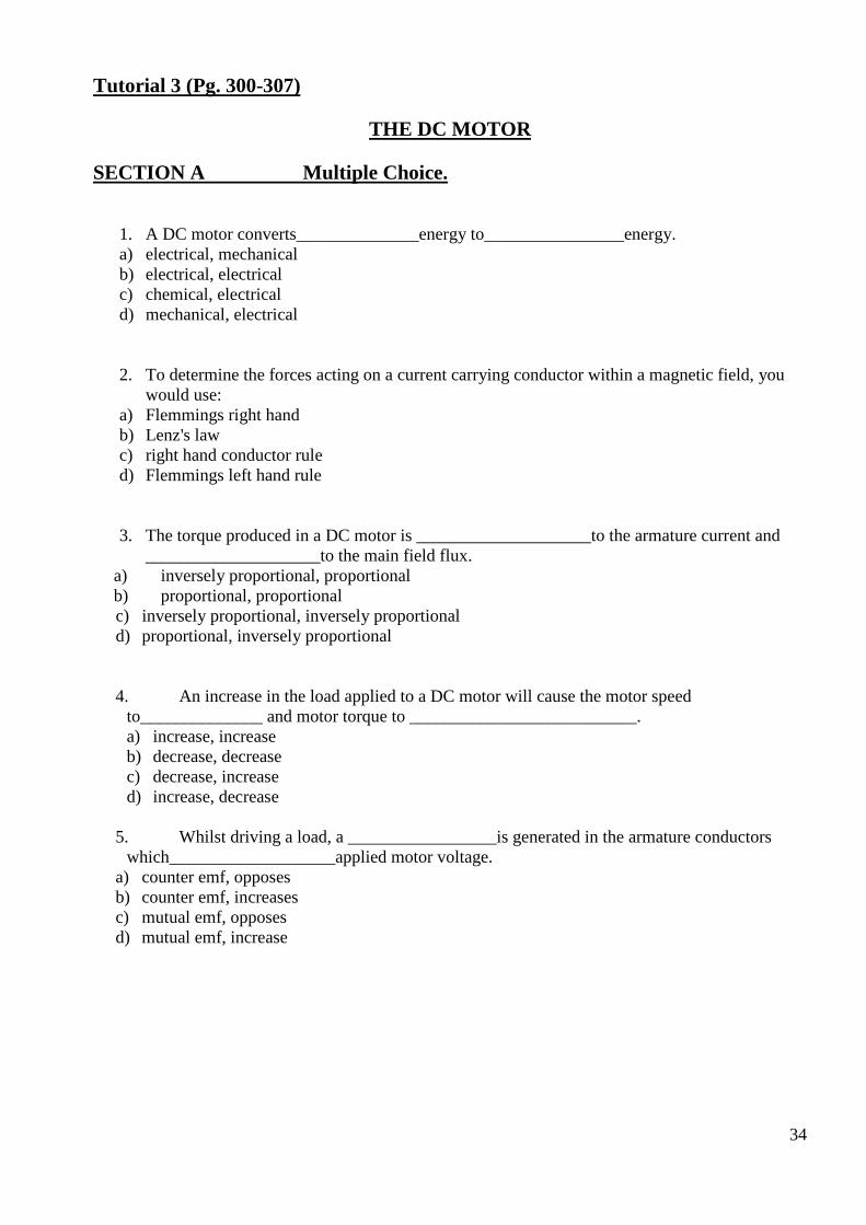
Tutorial 3 (Pg. 300-307)
THE DC MOTOR SECTION A Multiple Choice.
1. A DC motor converts______________energy to________________energy. a) electrical, mechanical b) electrical, electrical c) chemical, electrical d) mechanical, electrical
2. To determine the forces acting on a current carrying conductor within a magnetic field, you would use:
a) Flemmings right hand b) Lenz's law c) right hand conductor rule d) Flemmings left hand rule
3. The torque produced in a DC motor is ____________________to the armature current and ____________________to the main field flux.
a) inversely proportional, proportional b) proportional, proportionalc) inversely proportional, inversely proportional d) proportional, inversely proportional
4. An increase in the load applied to a DC motor will cause the motor speed to______________ and motor torque to __________________________. a) increase, increase b) decrease, decrease c) decrease, increase d) increase, decrease
5. Whilst driving a load, a _________________is generated in the armature conductors
which___________________applied motor voltage. a) counter emf, opposes b) counter emf, increases c) mutual emf, opposes d) mutual emf, increase
34

SECTION B Short Answer
1. The force acting upon a current carrying conductor depends on the _______________of the magnetic field, the__________________flowing in the conductor and the__________________ of the conductor within the magnetic field.
2. The torque developed within a DC motor is proportional to the__________________acting on the conductor and the ____________________________________ of the armature.
3. If the load applied to a DC motor is decreased, the: speed will__________________the back emf will__________________the armature current will__________________and the torque developed by the motor will__________________.
4. The emf generated within the armature conductors__________________the applied voltage, and is known as a__________________
5. The field system of a DC motor is mounted on the __________________and the current in the armature conductors is transferred from the supply via the_______________ and________________
6. The current flowing in the armature conductors is dependent on the _____________generated within the armature conductors.
7. If the load applied to a DC motor is increased, the speed will____________the back emf will__________________the armature current will__________________and the torque developed by the motor will__________________
8. Motor torque is produced when the main __________________reacts with the armature _________________
35
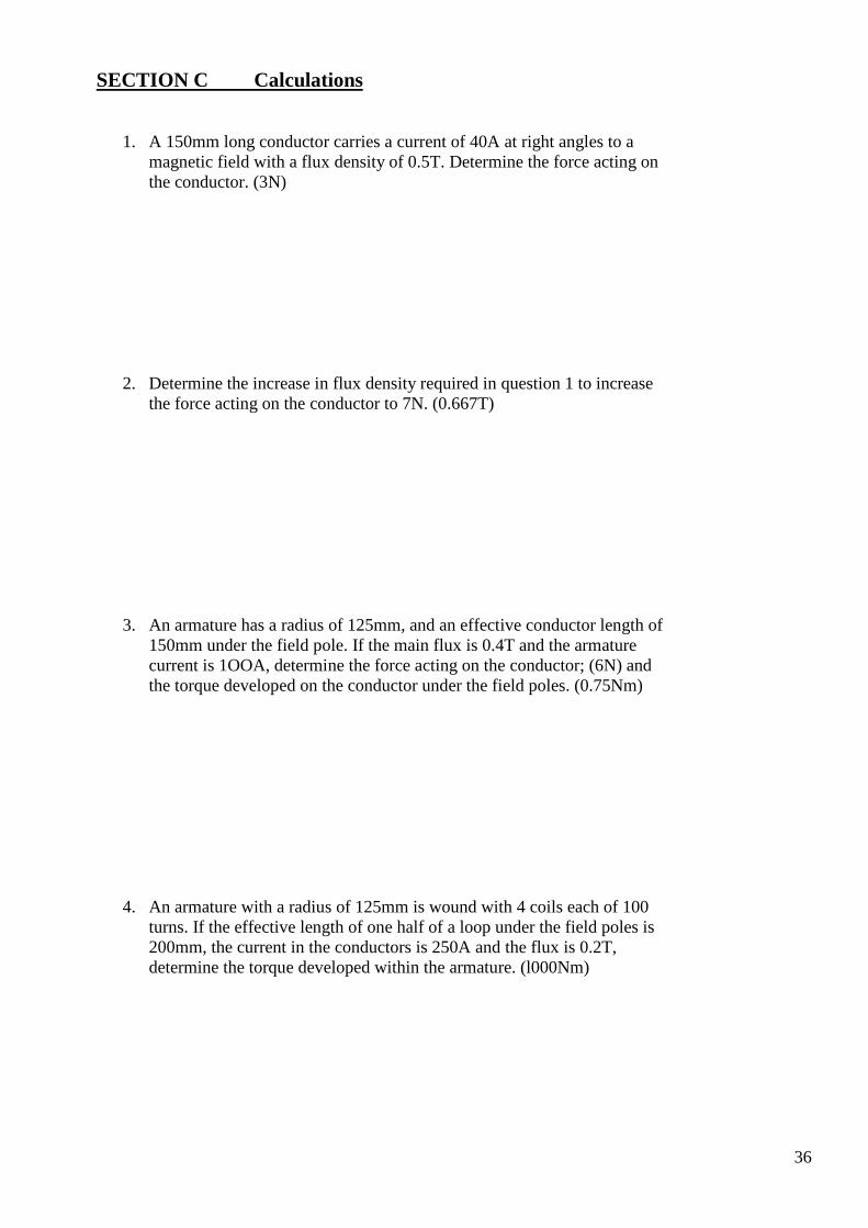
SECTION C Calculations
1. A 150mm long conductor carries a current of 40A at right angles to a magnetic field with a flux density of 0.5T. Determine the force acting on the conductor. (3N)
2. Determine the increase in flux density required in question 1 to increase the force acting on the conductor to 7N. (0.667T)
3. An armature has a radius of 125mm, and an effective conductor length of 150mm under the field pole. If the main flux is 0.4T and the armature current is 1OOA, determine the force acting on the conductor; (6N) and the torque developed on the conductor under the field poles. (0.75Nm)
4. An armature with a radius of 125mm is wound with 4 coils each of 100 turns. If the effective length of one half of a loop under the field poles is 200mm, the current in the conductors is 250A and the flux is 0.2T, determine the torque developed within the armature. (l000Nm)
36

5. A DC motor has a machine constant of 20, a main flux of 0.015Wb and runs at 750rpm. Determine the emf generated within the armature conductors. (225V)
6. If the motor in question 5 is connected to a 250V supply and has an armature circuit resistance of 0.150, determine the amount of current flowing in the armature. (167A)
7. The motor shown in figure 1 has a field flux of 0.0125Wb, runs at 250rpm, and has a machine constant of 8. For these conditions, determine the:
a. back emf; (25V) b. armature current; (30A) c. developed torque; (3Nm) d. armature circuit voltage drop. (3V)
37
SECTION D Drawings & Diagrams
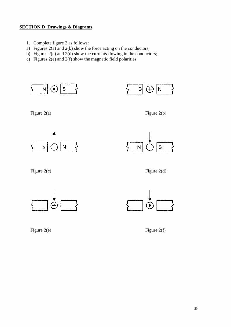
1. Complete figure 2 as follows: a) Figures 2(a) and 2(b) show the force acting on the conductors; b) Figures 2(c) and 2(d) show the currents flowing in the conductors; c) Figures 2(e) and 2(f) show the magnetic field polarities.
Figure 2(a) Figure 2(b)
Figure 2(c) Figure 2(d)
Figure 2(e) Figure 2(f)
38
PRACTICAL 4
DC MOTOR CHARACTERISTICS & REVERSAL PURPOSE: This practical assignment will be used to examine the characteristics and reversal of de motors. TO ACHIEVE THE PURPOSE OF THIS SECTION: At the end of this practical assignment the student will be able to: Connect shunt, series and compound motors. Plot the characteristics of shunt, series and compound motors. Reverse the direction of rotation of shunt, series and compound motors. EQUIPMENT:
1 x dual variable dc power supply (0-6A output for Armature during procedure 1) 1 x Baldor DC compound machine 1 x Betts eddy current load 1 x Betts Plate 1 x digital multimeter 2 x 0-5A analogue de ammeter 1 x tachometer 4mm connecting leads
-REMEMBER- - WORK SAFELY AT ALL
TIMES- Observe correct isolation procedures
39
PROCEDURE 1: SHUNT MOTOR
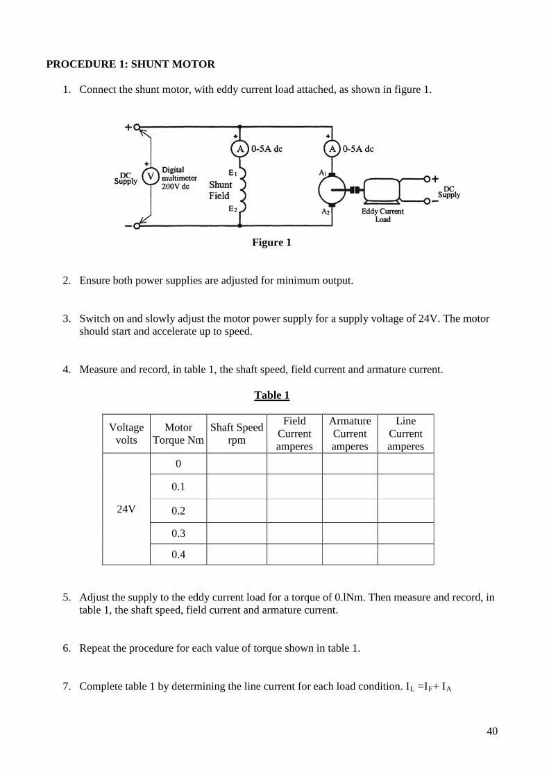
1. Connect the shunt motor, with eddy current load attached, as shown in figure 1.
Figure 1
2. Ensure both power supplies are adjusted for minimum output.
3. Switch on and slowly adjust the motor power supply for a supply voltage of 24V. The motor should start and accelerate up to speed.
4. Measure and record, in table 1, the shaft speed, field current and armature current.
Table 1
Voltage volts
Motor Torque Nm
Shaft Speed rpm
Field Current amperes
Armature Current amperes
Line Current amperes
24V
0
0.1
0.2
0.3
0.4
5. Adjust the supply to the eddy current load for a torque of 0.lNm. Then measure and record, in table 1, the shaft speed, field current and armature current.
6. Repeat the procedure for each value of torque shown in table 1.
7. Complete table 1 by determining the line current for each load condition. IL =IF+ IA
40
8. With the motor operating under no-load, note the direction of rotation of the motor shaft looking at the drive end.
Direction of rotation______________________ 9. Switch the motor off
10. Reverse the connections to the shunt field.
11. Switch the motor on and note the direction of rotation of the motor shaft looking at the drive
end. Direction of rotation _____________________
12. Do not proceed until the teacher checks your results and completes the progress table.
Progress Table 1
attempt 1 attempt2 attempt 3
A B C
PROCEDURE 2: SERIES MOTOR
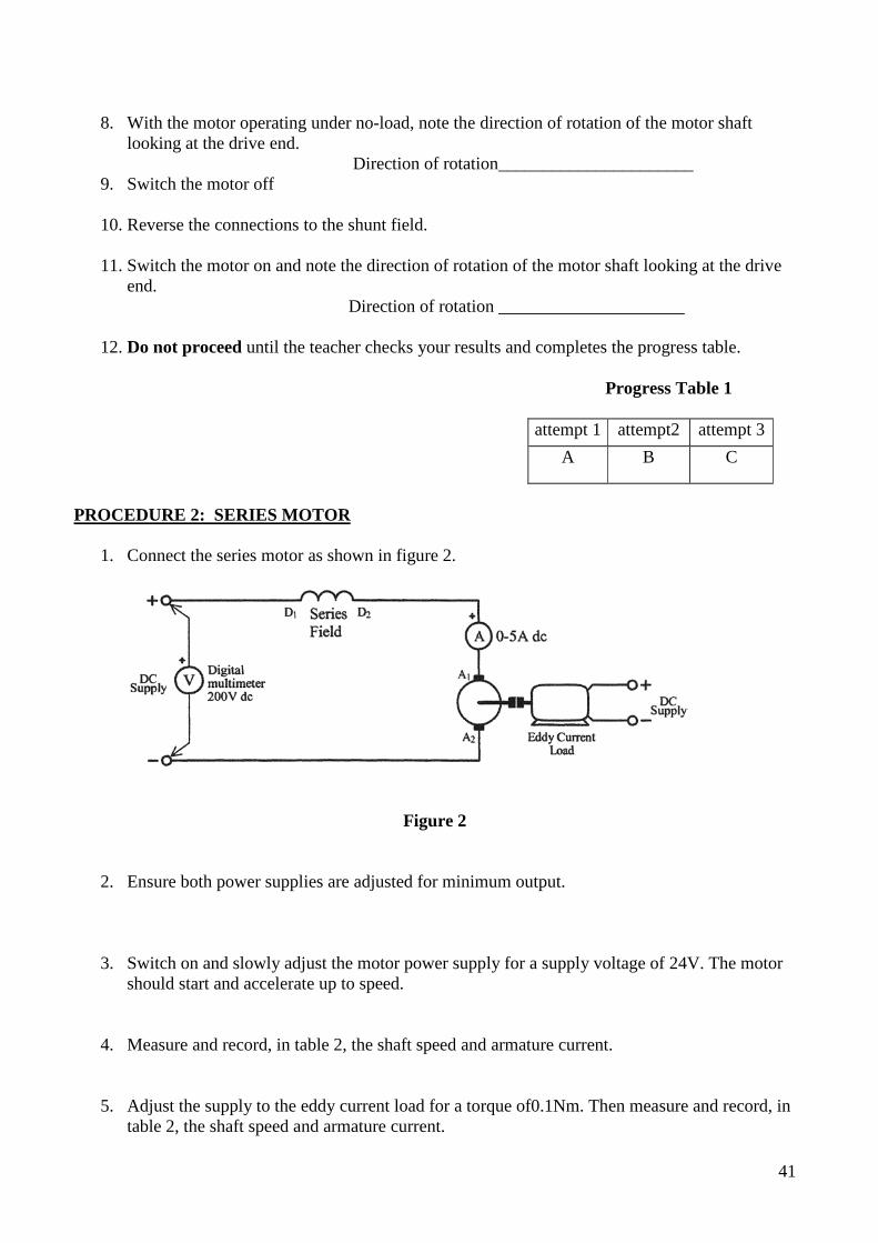
1. Connect the series motor as shown in figure 2.
Figure 2
2. Ensure both power supplies are adjusted for minimum output.
3. Switch on and slowly adjust the motor power supply for a supply voltage of 24V. The motor should start and accelerate up to speed.
4. Measure and record, in table 2, the shaft speed and armature current.
5. Adjust the supply to the eddy current load for a torque of0.1Nm. Then measure and record, in table 2, the shaft speed and armature current.
41

6. Repeat the procedure for each value of torque shown in table 2.
Table2
Voltage volts
Motor Torque Nm
Shaft Speed rpm
Armature Current amperes
24V
0
0.1
0.2
0.3
0.4
7. With the motor operating under no-load, note the direction of rotation of the motor shaft looking at the drive end.
Direction of rotation _____________________
8. Switch the motor off
9. Reverse the connections to the series field.
10. Switch the motor on and note the direction of rotation of the motor shaft looking at the drive end.
Direction of rotation _____________________
11. Do not proceed until the teacher checks your results and completes the progress table.
Progress Table 2
attempt 1 attempt 2 attempt 3
A B C
42
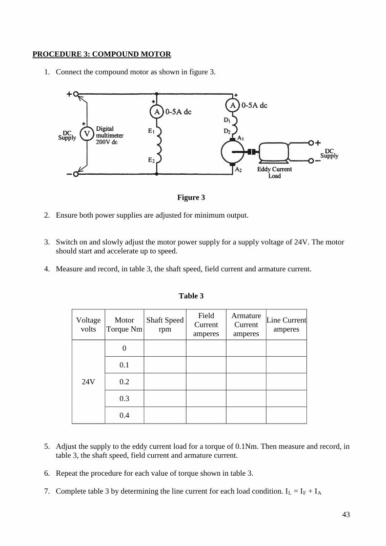
PROCEDURE 3: COMPOUND MOTOR
1. Connect the compound motor as shown in figure 3.
Figure 3
2. Ensure both power supplies are adjusted for minimum output.
3. Switch on and slowly adjust the motor power supply for a supply voltage of 24V. The motor should start and accelerate up to speed.
4. Measure and record, in table 3, the shaft speed, field current and armature current.
Table 3
Voltage volts
Motor Torque Nm
Shaft Speed rpm
Field Current amperes
Armature Current amperes
Line Current amperes
24V
0
0.1
0.2
0.3
0.4
5. Adjust the supply to the eddy current load for a torque of 0.1Nm. Then measure and record, in table 3, the shaft speed, field current and armature current.
6. Repeat the procedure for each value of torque shown in table 3.
7. Complete table 3 by determining the line current for each load condition. IL = IF + IA
43

8. With the motor operating under no-load, note the direction of rotation of the motor shaft looking at the drive end.
9. Switch the motor off.
Direction of rotation _____________________
10. Reverse the connections to the armature.
11. Switch the motor on and note the direction of rotation of the motor shaft looking at the drive
end.
Direction of rotation_____________________
12. Do not proceed until the teacher checks your results and completes the progress table.
Progress Table 3
attempt 1 attempt2 attempt 3
A B C
14. Disconnect the circuit. 15. Please return all equipment to its proper place, safely and carefully. OBSERVATIONS:
1. Of the three types of motor tested, which had the highest no-load speed? Why was this?
2. Of the three types of motor tested, which had the greatest variation in speed from no-load to full-load?
3. Of the three types of motor tested, which produced the highest torque for the least line current?
44

4. On the axes of the figure below, plot the speed-torque characteristics for each of the motors
tested. MOTOR SPEED
MOTOR TORQUE
5. Of the three types of motor tested, which required the least armature current to produce a torque of 0.4Nm? Explain why this was the case.
6. Which motor would be best for driving a near constant speed load that did not require a large value of driving torque?
2000
1800
1600
1400
1200
1000
800
600
400
200
0
0 0.1 0.2 0.3 0.4 0.5
45

7. On the axes of figure below, plot the torque-armature current characteristics for the three motors
Torque
Armature Current 8. Of the three types of motor tested, which would be best for driving a load requiring a high torque with limited speed loss?
0.5
0.4
0.3
0.2
0.1
0
1 2 3 4 5
46

Tutorial 4 Section A. Multiple Choice
DC MOTOR CHARACTERISTICS (Series, shunt, compound, starting resistance)
1. In a dc shunt motor, the___________and_______________ are constant.
a) field current, armature flux b) field flux, armature flux c) field flux, armature current d) field current, field flux
2. A dc series motor should never be run unloaded, as this will cause the motor to:
a) overheat b) over-speed c) overload d) slow down
3. DC compound motors are usually connected to be_______________compounded.
a) cumulatively b) differentially c) shunt d) series
4. To reverse the direction of rotation of a compound motor by field reversal, you would reverse
the connection to:
a) the series field only b) either the shunt or series field c) both the shunt and series fields d) the shunt field only
5. Whilst driving a load, a____________________ is generated in the armature conductors which ______________the applied motor voltage applied motor voltage.
a) counter emf, increases b) mutual emf, opposes c) mutual emf, increases d) counter emf, opposes
47
SECTION B Short Answer For the following questions, complete the statements with the word or phrase you think fits best.
1. State the three methods of connecting a single phase DC motor.
_____________________________
_____________________________
_____________________________
2. If the load connected to a shunt connected DC motor is increased, the motor speed will___________ the back emf will ___________, the armature current will ___________, and the motor torque will___________
3. A shunt connected DC motor is considered to be a _______________speed motor, and a series connected DC motor is considered to be a _______________speed motor.
4. When unloaded, the speed of a series connected DC motor is _______________due to the ___________field strength.
5. Over speeding of a series connected DC motor is prevented by having __________connected to the motor, or by having a light ___________connected across the supply.
6. If the load connected to a series connected DC motor is increased, the motor speed will_____________, the back emf will _______________the armature current will _______________and the motor torque will_______________
7. Series connected DC motors are commonly used for ______________and _____________
8. Compound connected DC motors are used for _____________speed applications where sudden changes in _________________may occur. Two examples are ___________________and _________________________.
9. Reversal of DOR in a DC motor is achieved by reversing the _______________connections or the ___________________ connections, but NOT both.
10. If reversing the DOR of a compound motor is required, reversing the __________________ connections is the simplest and preferred method as only ________________reconnection is required.
11. A common application of shunt connected DC motors is _______________________.
48
SECTION C Calculations
1. A 28V shunt connected motor draws a line current of 50A. Determine the back emf for these load conditions if the armature resistance is 0.05Ω, and the shunt field resistance is 56Ω. (25.53V)
2. If the back emf in question 1 decreases to 25V, determine the current drawn from the supply. (60.5A)
3. A 240V series connected motor has a line current of 40A. If the series field resistance is 0.4Ω and the armature resistance is 0.6Ω, determine the back emf generated within the armature circuit. (200V)
4. If the back emf in question 3 increases to 2I5V, determine the new value of line current drawn from the supply. (25A)
5. A 250V compound motor has a shunt field resistance of 100Ω, a series field resistance of 0.5Ω and an armature resistance of 0.8Ω.
a) draw an equivalent circuit for the motor, being sure to fully label the circuit and show all motor currents;
b) if the back emf is 216V, determine the current drawn from the supply; (28.65A)
c) if the load current increases to 45A, determine the back emf now generated within the
armature (l94.75V)
49
SECTION D Drawings & Diagrams
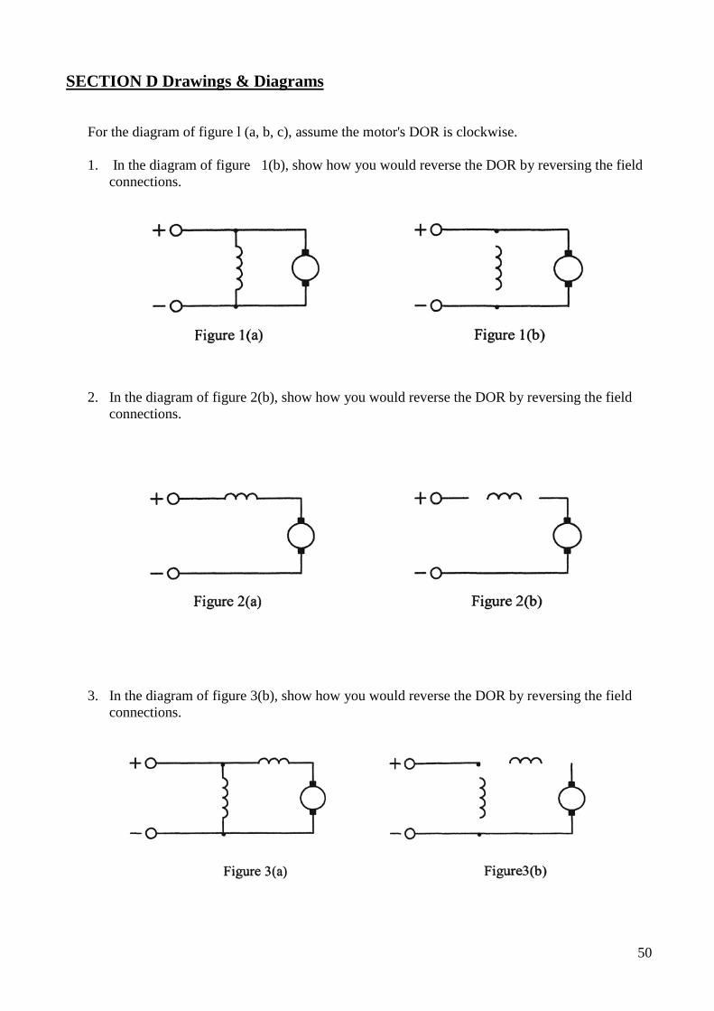
For the diagram of figure l (a, b, c), assume the motor's DOR is clockwise.
1. In the diagram of figure 1(b), show how you would reverse the DOR by reversing the field connections.
2. In the diagram of figure 2(b), show how you would reverse the DOR by reversing the field connections.
3. In the diagram of figure 3(b), show how you would reverse the DOR by reversing the field connections.
50
PRACTICAL 5
DC MOTOR STARTING PURPOSE:
This practical assignment will be used to examine the locked armature characteristics of a shunt motor and the determination of starting resistance to limit starting current to a prescribed value. TO ACHIEVE THE PURPOSE OF THIS SECTION:
• At the end of this practical assignment the student will be able to: • Connect shunt motor. • Carry out a locked armature test. • Determine the value of added resistance required to limit armature starting current to a
specified value. EQUIPMENT: 1 x dual variable dc power supply (0-6A output) 1 x Betts dc compound machine 1 x Betts flywheel 1 x Betts plate 1 x digital multimeter 1 x 0-5A analogue dc ammeter 1 x 0-10A AVO dc –(30A DC Analog from store) 1 x 1Ω and 5Ω, 10W resistors. 4mm connecting leads
·REMEMBER· -WORK SAFELY AT ALL TIMES· Observe correct isolation procedures
51
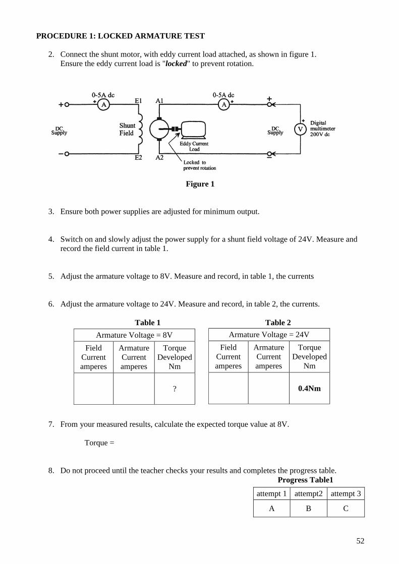
PROCEDURE 1: LOCKED ARMATURE TEST
2. Connect the shunt motor, with eddy current load attached, as shown in figure 1. Ensure the eddy current load is "locked" to prevent rotation.
Figure 1
3. Ensure both power supplies are adjusted for minimum output.
4. Switch on and slowly adjust the power supply for a shunt field voltage of 24V. Measure and record the field current in table 1.
5. Adjust the armature voltage to 8V. Measure and record, in table 1, the currents
6. Adjust the armature voltage to 24V. Measure and record, in table 2, the currents. Table 1 Table 2
7. From your measured results, calculate the expected torque value at 8V.
Torque =
8. Do not proceed until the teacher checks your results and completes the progress table.
Progress Table1
Armature Voltage = 8V Field
Current amperes
Armature Current amperes
Torque Developed
Nm
?
Armature Voltage = 24V Field
Current amperes
Armature Current amperes
Torque Developed
Nm
0.4Nm
attempt 1 attempt2 attempt 3
A B C
FLY WHEEL HOLD FOR LOCKED ROTOR
AVO 10 Amps
52
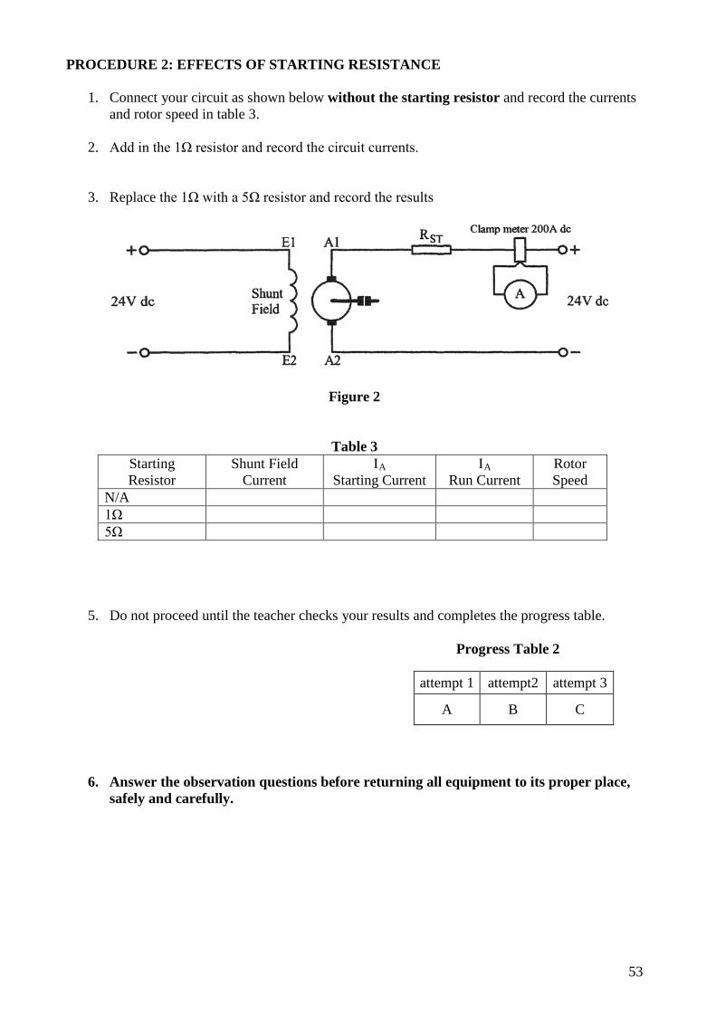
PROCEDURE 2: EFFECTS OF STARTING RESISTANCE
1. Connect your circuit as shown below without the starting resistor and record the currents and rotor speed in table 3.
2. Add in the 1Ω resistor and record the circuit currents.
3. Replace the 1Ω with a 5Ω resistor and record the results
Figure 2
Table 3 Starting Resistor
Shunt Field Current
IA Starting Current
IA Run Current
Rotor Speed
N/A 1Ω 5Ω
5. Do not proceed until the teacher checks your results and completes the progress table.
Progress Table 2
6. Answer the observation questions before returning all equipment to its proper place, safely and carefully.
attempt 1 attempt2 attempt 3
A B C
AVO 10 Amps
53

OBSERVATIONS:
1. What effect did the added starting resistance have on the armature motor starting currents?
2. What effect did the added starting resistance have on the motor rated rotor speed?
3. What effect did the added starting resistance have on the time taken to reach rated rotor speed?
4. Should the starting resistance be left in circuit once the motor is at full speed? Explain your answer.
5. What effect did the starting resistance have on the current taken by the shunt field?
54
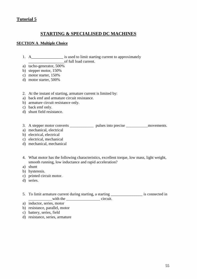
Tutorial 5
STARTING & SPECIALISED DC MACHINES SECTION A Multiple Choice
1. A________________ is used to limit starting current to approximately __________________of full load current.
a) tacho-generator, 500% b) stepper motor, 150% c) motor starter, 150% d) motor starter, 500%
2. At the instant of starting, armature current is limited by: a) back emf and armature circuit resistance. b) armature circuit resistance only. c) back emf only. d) shunt field resistance.
3. A stepper motor converts ____________ pulses into precise ___________movements. a) mechanical, electrical b) electrical, electrical c) electrical, mechanical d) mechanical, mechanical
4. What motor has the following characteristics, excellent torque, low mass, light weight, smooth running, low inductance and rapid acceleration?
a) shunt b) hysteresis. c) printed circuit motor. d) series.
5. To limit armature current during starting, a starting ________________ is connected in ____________with the _________________ circuit.
a) inductor, series, motor b) resistance, parallel, motor c) battery, series, field d) resistance, series, armature
55
SECTION B Short Answer
1. Starting resistors used with large motors drawing heavy currents are usually made in the form of____________________________________.
2. Starting current is usually limited to about _____________ of full load armature current. This ensures that the motor can start under _______________and rapidly _______________to full load speed.
3. If a starting resistor was connected in series with the shunt field, the motor would __________ be able to develop the correct __________ . Therefore, starting resistors are connected in __________with the ______________.
SECTION C Calculations
1. A 28V shunt connected motor has a full load current of 50A. If the resistance of the shunt field is 56Ω and the armature circuit resistance is 0.08Ω, determine the;
a) armature current at start with no starting resistance employed (350A)
b) Value of starting resistance required to limit the starting current to 150% of full load armature current. (297mΩ) 2. A 150V series motor has a full load current of 75A. If the armature circuit resistance is
0.25Ω, determine the:
a) Starting current drawn from the supply with no starting resistance employed; (600A)
b) The value of starting resistance required to limit starting current to 175% of full load current. (0.893Ω)
56
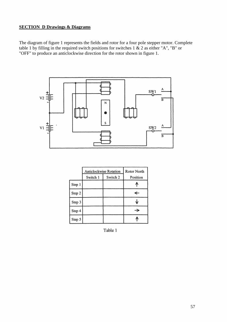
SECTION D Drawings & Diagrams The diagram of figure 1 represents the fields and rotor for a four pole stepper motor. Complete table 1 by filling in the required switch positions for switches 1 & 2 as either "A", "B" or "OFF" to produce an anticlockwise direction for the rotor shown in figure 1.
57
DC GENERATORS & MOTORS – REVISION Chapter 13 – DC Generators True/False 1. A DC generator is almost identical to a DC motor. 2. Pole pieces are made from steel laminations. 3. DC machines never use brushes in their construction. 4. Interpoles are used to reduce armature reaction on the main magnetic field. 5. DC generators always need an external source of DC. Multiple Choice 1. The part of a DC generator that switches the current flow as the machine rotates is called a: A. commutator B. commuter C. slip ring D. switch 2. The formula for calculating the generated voltage in a DC generator is: A. l=eBv B. v=Ble C. e=Blv D. v=IR 3. The maximum voltage appears at the terminals of a DC generator when: A. maximum load occurs B. no load occurs C. half load occurs D. varying load occurs 4. If self excited machines have their direction reversed they will: A. generate higher voltage B. generate lower voltage C. run faster D. generate no voltage
58

5. How many parallel paths are there in a wave wound armature: A. 4 B. 3 C. 2 D. 1 Completion 1. A DC generator is driven by a device known as a __________________________. 2. A basic alternator is converted to a DC generator by adding a ________________. 3. A practical DC generator uses __________________ to increase conductor length. 4. The metal piece that the field coils are mounted on is called a _________________. 5. Brushes in a DC generator are normally made from a ___________ based material. Short Answer 1. A lap wound armature in a four pole DC generator has 220 conductors that are in a flux field of
0.08 Webers and is rotated at 1000 rpm. What is the value of voltage generated in the armature? 2. What is the effect on armature voltage if the magnetic flux is increased? 3. What would be the % voltage regulation in a shunt generator with a no load voltage of 660 volts
and a full load voltage of 625 volts? 4. If a prime mover input power is 120 kW and a DC generator produces 111 kW what is the
efficiency of the machine? 5. If a DC generator has an efficiency of 95% what is the input power required to produce an
output power of 25kW?
59
Chapter 14 – DC Motors True/False 1. A DC motor converts electrical energy to mechanical energy. 2. Fleming’s right-hand rule is used for motors. 3. As current passes through a DC motor it produces torque. 4. If a DC motor is driven faster than its normal speed it can become a generator. 5. The speed of a DC motor is directly proportional to its terminal voltage. Multiple Choice 1. When a DC motor of any type is first started, the only resistance to current flow is that offered
by the motor’s DC: A. resistance B. inductance C. capacitance D. springs 2. The most common method of braking a DC motors is: A. dynamic braking B. dynamo braking C. capacitive braking D. reactive braking 3. To reverse a DC motor you must: A. reverse the armature and the field connections B. reverse the supply C. swap the brushes D. reverse either the armature or the field connections 4. Armature reaction in DC motors can be compensated for by the addition: A. lap windings B. interpoles C. wave windings D. rheostat 5. DC motor starting current should be limited to about: A. 100% B. 50% C. 150% D. 500%
60

Completion 1. The simplest method of controlling the field current is with a _________ in series with the shunt
field coils. 2. Brushless DC motors use _________________________ circuits to switch field coils. 3. Like all machines DC motors have _____________ which determine their efficiency. Short Answer 1. An armature has an effective conductor length of 15 metres and is passing a current of 11
amperes. The armature conductors are at right angles to the magnetic field that has a flux density of 0.2 tesla, find the force acting on the conductors?
2. What is the torque produced by an armature that has a force of 30 newtons and has a diameter of
100mm? 3. A DC motor has a machine constant (k) of 95 and a main flux field of 0.04 Wb. What is the
torque delivered by the motor when the armature current is 45 A? 4. If a DC motor is running at 1000 rpm and is producing a torque of 200Nm what is its power
output? 5. Determine the efficiency of a18kW, 300V DC motor that is taking a full load current of 75A?
61
62
63