Practical Wall Bracing - Fairfax County · Version: 2012.1, 02/12/2018 Fairfax County,...
10
Fairfax County, Virginia Practical Wall Bracing Based on the 2012 Virginia Residential Code The information herein provides guidelines for complying with the most common Practical Wall Bracing provisions of the Virginia Residential Code, Section R602.12, and are not representative of all the conditions that may be required. A broader wall bracing methodology, which provides more flexibility and design options, is available. See our companion publication entitled “Classic” Wall Bracing based on Section R602.10.
Transcript of Practical Wall Bracing - Fairfax County · Version: 2012.1, 02/12/2018 Fairfax County,...

Fairfax County, Virginia
Practical Wall Bracing Based on the 2012 Virginia Residential Code
The information herein provides guidelines for complying with the most common Practical Wall Bracing provisions of the Virginia Residential Code, Section R602.12, and are not representative of all the conditions that may be required.
A broader wall bracing methodology, which provides more flexibility and design options, is available. See our companion publication entitled “Classic” Wall Bracing based on Section R602.10.
Version: 2012.1, 02/12/2018 Fairfax County, Virginia - Practical Wall Bracing Page 2 of 10
Fairfax County, Virginia Practical Wall Bracing
CONTENTS
Contents
Resisting Wind Load...............................................................3 Braced Wall Panels .................................................................3 Circumscribed Rectangles ......................................................5 Braced Wall Panel Assignment ..............................................6 Bracing Rules ..........................................................................6 Braced Wall Panel Connections ..............................................8 Other Design Considerations ................................................10
Fairfax County is committed to a policy of nondiscrimination in all county programs, services and activities. To request this information in an alternative format call 703-222-0801, TTY 711 or write the Customer and Technical Support Center at 12055 Government Center Parkway, Suite 216, Fairfax, VA 22035-5504. Please allow seven working days for preparation of material.

Version: 2012.1, 02/12/2018 Fairfax County, Virginia - Practical Wall Bracing Page 3 of 10
RESISTING WIND LOAD
All buildings must be designed to resist wind load. Unlike snow load which acts vertically and downward only, wind load acts horizontally and in any direction.
The design wind load on a structure is based on the local wind speed which is 90 mph for Fairfax County. Due to the way wind is measured, this translates to a weak Category 1 hurricane.
The structural system of a house is designed to transfer wind load from where it is applied all the way to the ground; this is called “load path.” Wind load is resisted by the walls parallel to the direction of the wind. For example, in a simple one-story house, as shown in
FIGURE 1, wind against the end wall would cause the roof to move in the direction of the wind, but the movement is resisted by the bracing in the side walls parallel to the wind.
This process is similar for houses with multiple floors. However, in such cases, the walls of the first floor have the added responsibility of resisting the forward movement of all the floors and the roof above.
The Virginia Residential Code accounts for the properties and characteristics of wind through the construction requirements in this publication.
FIGURE 1: WIND LOAD APPLIED TO HOUSE
BRACED WALL PANELS
As shown in FIGURE 2, a typical wall will rack due to wind load if no bracing is provided. When installed along a wall, bracing prevents this lateral displacement, see FIGURE 3.
The code defines a “braced wall panel” as a sheathed, full-height (12-foot maximum) section of wall constructed to resist wind load and placed on a wall in specified lengths and locations.
Oriented strand board (OSB) is the required sheathing for exterior braced wall panels. Practical Wall Bracing further requires OSB to be applied over the entire exterior of your house or addition, including areas above and below wall openings. Gypsum board is required on the opposite side of all exterior braced wall panels. Gypsum board is also the required bracing material for braced wall panels located on interior walls.
FIGURE 2: RACKING DUE TO WIND LOAD
wind

Version: 2012.1, 02/12/2018 Fairfax County, Virginia - Practical Wall Bracing Page 4 of 10
FIGURE 3: BRACED WALL PANELS
A braced wall panel must have a specified minimum length based on its location. Exterior walls rely on the wall height and the vertical dimension of the adjacent opening to determine minimum length. See TABLE 1 and the example below. When a panel has an opening on each side of differing heights, the taller opening governs the panel length. The minimum length of interior braced wall panels is 48 inches.
Contributing length is the value in which the panels can contribute to the minimum required length of bracing. See Page 7. Exterior braced wall panels
contribute their actual length while interior braced wall panels only contribute half of their actual length.
For those applications where it is difficult to place a full-length braced wall panel portal frames, laboratory tested narrow panels, can be utilized. The most common portal frame, shown in FIGURE 4, is permitted to be constructed up to 12 feet tall with a contributing length equal to 1.5 times its actual length. For more information on how to construct a portal frame, consult the 2012 Virginia Residential Code at fairfaxcounty.gov.
TABLE 1: MINIMUM LENGTH OF EXTERIOR BRACED WALL PANELS Adjacent opening Minimum Length (in) vertical dimension Wall Height
(in) 8 ft 9 ft 10 ft 11 ft 12 ft ≤ 64 24 27 30 33 36 ≤ 72 27 27 30 33 36 ≤ 80 30 30 30 33 36 > 80 36 36 36 40 40
EXAMPLE: Length of Exterior Panel
In the wall above, find the minimum length of the panel between the window and the door. 1. Use 80 inches as the governing opening height. 2. Use 11 feet as the wall height. 3. Per TABLE 1, the minimum length of the panel =
33 inches.
EXAMPLE: Contributing Length
In the interior wall above, calculate the contributing length of the 50-inch interior braced wall panel. 1. The formula for contributing length = 0.5 x actual
length. 2. Therefore, the contributing length = 50 x 0.5 =
25 inches.
length
heig
ht
wind
80” 62
”
11’-0
”
? 50”

Version: 2012.1, 02/12/2018 Fairfax County, Virginia - Practical Wall Bracing Page 5 of 10
OVER CONCRETE OR MASONRY BLOCK FOUNDATION
OSB SHEATING TOTOP OF FLOORFRAMING
OSB SHEATHINGOVER BAND BOARD
OVER RAISED WOOD FLOOR - FRAMING ANCHOR OPTION(WHEN PORTAL SHEATHING DOES NOT LAP OVER BAND OR RIM JOIST)
OVER RAISED WOOD FLOOR - OVERLAP OPTION(WHEN PORTAL SHEATHING LAPS OVER BAND OR RIM BOARD)
FASTEN TOP PLATE TOUNDERSIDE OFHEADER WITH TWOROWS OF 16d NAILS AT3" O.C.
TENSIONSTRAP (REAR),EACH SIDE
DOUBLE 2X4sSHEATHED IN 716" OSBWITH 8d NAILS AT 3"O.C.
LENGTH PER TABLE 4
(2) 1/2" DIAMETER ANCHORBOLTS WITH 2"x2"x3/16"PLATE WASHERS
BLOCKED SPLICEDPERMITTED WITHIN24' OF MID-HEIGHTOF PANEL
TENSION STRAP
MIN. 3" X 11-1/4" NET HEADERSTEEL HEADER PROHIBITED
12' M
AX T
OTA
L W
ALL
HEI
GH
TSINGLE PORTAL
10' M
AX. H
EIG
HT 8d NAILS IN 3" GRID PATTERN
PONY WALLHEIGHT
DOUBLE PORTAL
(2) FRAMING ANCHORSAPPLIED ACROSSSHEATHING JOINT WITHA CAPACITY OF 670 LBSIN THE HORIZONTALAND VERTICALDIRECTIONS
MIN
.O
VER
LAP
9-1/
4"
FRONT ELEVATION SECTION
OSB OVER BAND BOARD
ATTACH SHEATHING TOBAND OR RIM JOISTWITH 8D COMMONNAILS AT 3" O.C. TOPAND BOTTOM
2' TO 18' PERMITTED OPENING
OSB OVER BAND BOARD
FIGURE 4: PORTAL FRAME
CIRCUMSCRIBED RECTANGLES
“Circumscribed rectangles,” are rectangles that you draw around a house or addition, or portions thereof, that help you determine the amount and spacing of bracing required to ensure your structure is sufficient to resist horizontal load.
The rectangle(s) must enclose offsets and projections such as sunrooms, garages and bay windows. However, chimneys and open structures, such as decks, porches and carports are to be excluded. See FIGURE 5 for an example of what to include and exclude from a circumscribed rectangle.
You can place numerous rectangles within your house or addition, as shown in FIGURE 6, provided
no rectangle has a side with a length greater than 80 feet and the ratio of long to short side does not exceed 3:1. However, the sides of adjacent rectangles that are common along any of their length require additional design considerations.
A design which places one rectangle around the entire house will rely solely on exterior bracing to resist horizontal load. Placing multiple rectangles in a house will spread the resistance of horizontal load to interior walls, but it will also create a more complicated design.

Version: 2012.1, 02/12/2018 Fairfax County, Virginia - Practical Wall Bracing Page 6 of 10
FIGURE 5: CIRCUMSCRIBED RECTANGLE ELEMENTS
FIGURE 6: MULTIPLE RECTANGLES
BRACED WALL PANEL ASSIGNMENT
Braced wall panels are required to be “assigned” to rectangle sides and count towards the code-required bracing for each side. See Page 7. On exterior walls, braced wall panels are assigned to the rectangle side
on which they are located or in which they face. See FIGURE 7. Interior braced wall panels are assigned to the rectangle side on which they are located or in which they face up to 4 feet away. See FIGURE 7.
FIGURE 7: BRACED WALL PANEL ASSIGNMENT
BRACING RULES
The placement and amount of bracing for each rectangle side is required to meet the all four of the following rules. 1. Location: A braced wall panel must be located at or start within 12 feet from each house corner and, if
using multiple rectangles, each rectangle corner. See FIGURE 8. 2. Spacing: The distance between adjacent braced wall panels on each house wall or rectangle side cannot
exceed 20 feet. See FIGURE 8. 3. Number: House walls greater than 8 feet long must have a least one braced wall panel, and house walls
less than 8 feet long are permitted to have no braced wall panels. See FIGURE 8.
ELEMENTS TO INCLUDE
ELEMENTS TO EXCLUDE
EXTERIOR ASSIGNMENT INTERIOR ASSIGNMENT
Version: 2012.1, 02/12/2018 Fairfax County, Virginia - Practical Wall Bracing Page 7 of 10
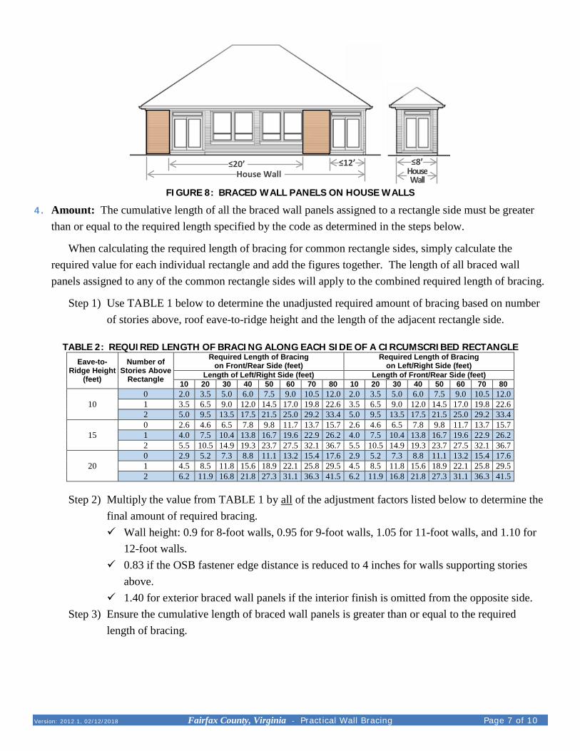
FIGURE 8: BRACED WALL PANELS ON HOUSE WALLS
4. Amount: The cumulative length of all the braced wall panels assigned to a rectangle side must be greater than or equal to the required length specified by the code as determined in the steps below.
When calculating the required length of bracing for common rectangle sides, simply calculate the required value for each individual rectangle and add the figures together. The length of all braced wall panels assigned to any of the common rectangle sides will apply to the combined required length of bracing.
Step 1) Use TABLE 1 below to determine the unadjusted required amount of bracing based on number of stories above, roof eave-to-ridge height and the length of the adjacent rectangle side.
TABLE 2: REQUIRED LENGTH OF BRACING ALONG EACH SIDE OF A CIRCUMSCRIBED RECTANGLE
Eave-to-Ridge Height
(feet)
Number of Stories Above
Rectangle
Required Length of Bracing on Front/Rear Side (feet)
Required Length of Bracing on Left/Right Side (feet)
Length of Left/Right Side (feet) Length of Front/Rear Side (feet) 10 20 30 40 50 60 70 80 10 20 30 40 50 60 70 80
10 0 2.0 3.5 5.0 6.0 7.5 9.0 10.5 12.0 2.0 3.5 5.0 6.0 7.5 9.0 10.5 12.0 10 1 3.5 6.5 9.0 12.0 14.5 17.0 19.8 22.6 3.5 6.5 9.0 12.0 14.5 17.0 19.8 22.6 10 2 5.0 9.5 13.5 17.5 21.5 25.0 29.2 33.4 5.0 9.5 13.5 17.5 21.5 25.0 29.2 33.4 15 0 2.6 4.6 6.5 7.8 9.8 11.7 13.7 15.7 2.6 4.6 6.5 7.8 9.8 11.7 13.7 15.7 15 1 4.0 7.5 10.4 13.8 16.7 19.6 22.9 26.2 4.0 7.5 10.4 13.8 16.7 19.6 22.9 26.2 15 2 5.5 10.5 14.9 19.3 23.7 27.5 32.1 36.7 5.5 10.5 14.9 19.3 23.7 27.5 32.1 36.7 20 0 2.9 5.2 7.3 8.8 11.1 13.2 15.4 17.6 2.9 5.2 7.3 8.8 11.1 13.2 15.4 17.6 20 1 4.5 8.5 11.8 15.6 18.9 22.1 25.8 29.5 4.5 8.5 11.8 15.6 18.9 22.1 25.8 29.5 20 2 6.2 11.9 16.8 21.8 27.3 31.1 36.3 41.5 6.2 11.9 16.8 21.8 27.3 31.1 36.3 41.5
Step 2) Multiply the value from TABLE 1 by all of the adjustment factors listed below to determine the final amount of required bracing. Wall height: 0.9 for 8-foot walls, 0.95 for 9-foot walls, 1.05 for 11-foot walls, and 1.10 for
12-foot walls. 0.83 if the OSB fastener edge distance is reduced to 4 inches for walls supporting stories
above. 1.40 for exterior braced wall panels if the interior finish is omitted from the opposite side.
Step 3) Ensure the cumulative length of braced wall panels is greater than or equal to the required length of bracing.
≤20’ House Wall
≤12’ ≤8’ House Wall
Version: 2012.1, 02/12/2018 Fairfax County, Virginia - Practical Wall Bracing Page 8 of 10
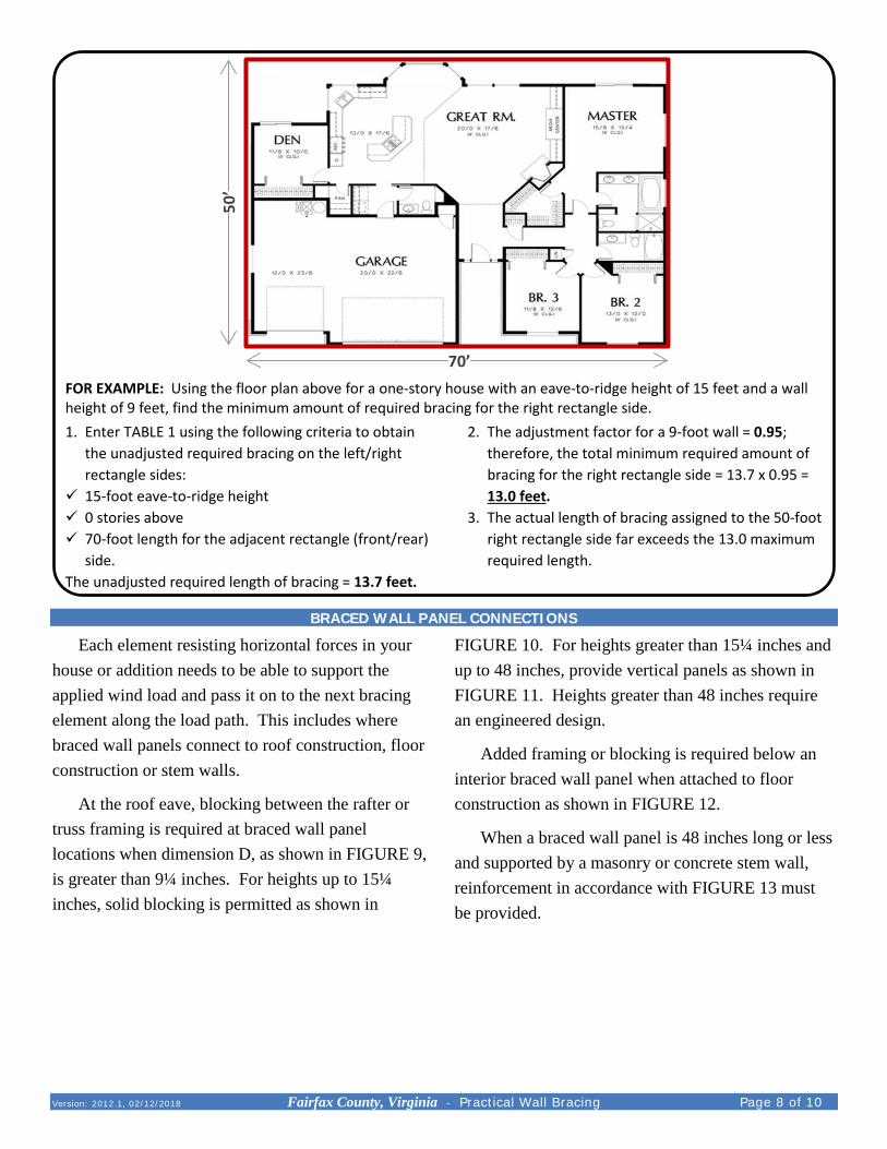
FOR EXAMPLE: Using the floor plan above for a one-story house with an eave-to-ridge height of 15 feet and a wall height of 9 feet, find the minimum amount of required bracing for the right rectangle side.1. Enter TABLE 1 using the following criteria to obtain
the unadjusted required bracing on the left/right rectangle sides:
15-foot eave-to-ridge height 0 stories above 70-foot length for the adjacent rectangle (front/rear)
side. The unadjusted required length of bracing = 13.7 feet.
2. The adjustment factor for a 9-foot wall = 0.95; therefore, the total minimum required amount of bracing for the right rectangle side = 13.7 x 0.95 = 13.0 feet.
3. The actual length of bracing assigned to the 50-foot right rectangle side far exceeds the 13.0 maximum required length.
BRACED WALL PANEL CONNECTIONS
Each element resisting horizontal forces in your house or addition needs to be able to support the applied wind load and pass it on to the next bracing element along the load path. This includes where braced wall panels connect to roof construction, floor construction or stem walls.
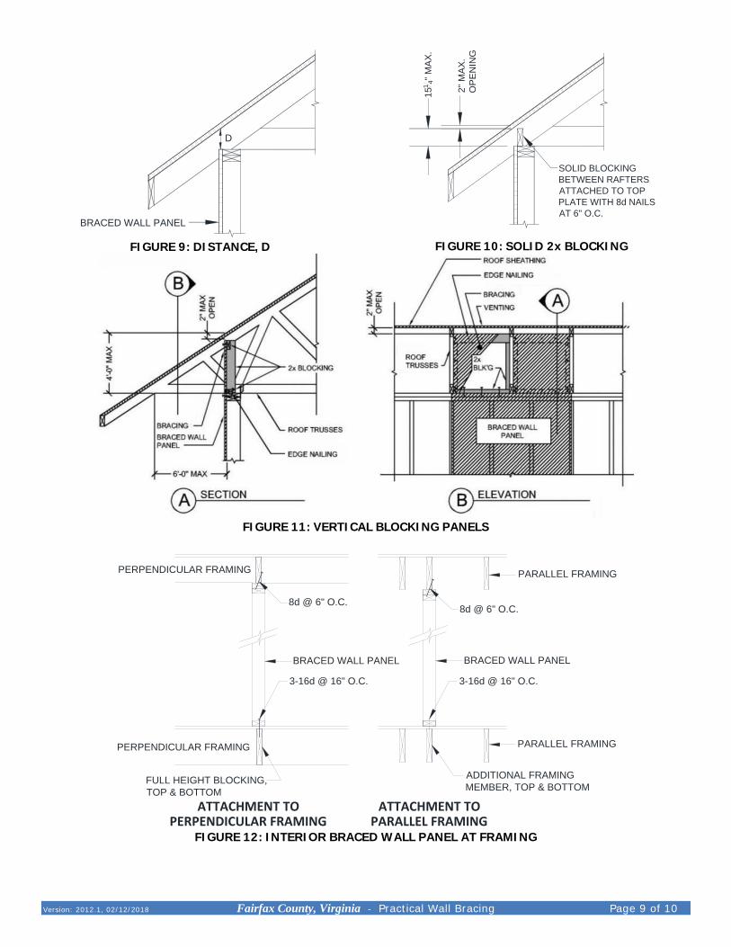
At the roof eave, blocking between the rafter or truss framing is required at braced wall panel locations when dimension D, as shown in FIGURE 9, is greater than 9¼ inches. For heights up to 15¼ inches, solid blocking is permitted as shown in
FIGURE 10. For heights greater than 15¼ inches and up to 48 inches, provide vertical panels as shown in FIGURE 11. Heights greater than 48 inches require an engineered design.
Added framing or blocking is required below an interior braced wall panel when attached to floor construction as shown in FIGURE 12.
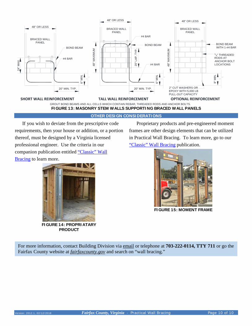
When a braced wall panel is 48 inches long or less and supported by a masonry or concrete stem wall, reinforcement in accordance with FIGURE 13 must be provided.
50’
70’
Version: 2012.1, 02/12/2018 Fairfax County, Virginia - Practical Wall Bracing Page 9 of 10
D
BRACED WALL PANEL
FIGURE 9: DISTANCE, D
SOLID BLOCKINGBETWEEN RAFTERSATTACHED TO TOPPLATE WITH 8d NAILSAT 6" O.C.
151 4"
MAX
.
2" M
AX.
OPE
NIN
G
FIGURE 10: SOLID 2x BLOCKING
FIGURE 11: VERTICAL BLOCKING PANELS
FULL HEIGHT BLOCKING,TOP & BOTTOM
PARALLEL FRAMING
PARALLEL FRAMING
8d @ 6" O.C.
BRACED WALL PANEL
3-16d @ 16" O.C.
ADDITIONAL FRAMINGMEMBER, TOP & BOTTOM
BRACED WALL PANEL
3-16d @ 16" O.C.
8d @ 6" O.C.
PERPENDICULAR FRAMING
PERPENDICULAR FRAMING
ATTACHMENT TOPARALLEL FRAMING
ATTACHMENT TOPERPENDICULAR FRAMING
FIGURE 12: INTERIOR BRACED WALL PANEL AT FRAMING
Version: 2012.1, 02/12/2018 Fairfax County, Virginia - Practical Wall Bracing Page 10 of 10
OPTIONAL REINFORCEMENTTALL WALL REINFORCEMENTSHORT WALL REINFORCEMENT
24" M
AX.
48" M
AXIM
UM
48" M
AXIM
UM
20" MIN. TYP.
6" M
IN.
48" OR LESS
2" CUT WASHERS OREPOXY WITH 5,000 LBPULL-OUT CAPACITY
BOND BEAMWITH 1-#4 BAR
#4 BAR
BOND BEAM
20" L
AP, T
YP.
20" MIN. TYP.
#4 BAR
BOND BEAM
58" THREADED
RODS ATANCHOR BOLTLOCATIONS
#4 BARBRACED WALL
PANEL
GROUT BOND BEAMS AND ALL CELLS WHICH CONTAIN REBAR, THREADED RODS AND ANCHOR BOLTS.
48" OR LESS 48" OR LESS
6" M
IN.
BRACED WALLPANEL
8" M
IN.
BRACED WALLPANEL
FIGURE 13: MASONRY STEM WALLS SUPPORTING BRACED WALL PANELS
OTHER DESIGN CONSIDERATIONS
If you wish to deviate from the prescriptive code requirements, then your house or addition, or a portion thereof, must be designed by a Virginia licensed professional engineer. Use the criteria in our companion publication entitled “Classic” Wall Bracing to learn more.
FIGURE 14: PROPRIATARY
PRODUCT
Proprietary products and pre-engineered moment frames are other design elements that can be utilized in Practical Wall Bracing. To learn more, go to our “Classic” Wall Bracing publication.
FIGURE 15: MOMENT FRAME
For more information, contact Building Division via email or telephone at 703-222-0114, TTY 711 or go the Fairfax County website at fairfaxcounty.gov and search on “wall bracing.”