![Opt-TDMA/DCR: Optimized TDMA Deterministic Collision ......Firstly, we present probabilistic slot reservation approaches. DRAND [11] is a TDMA reservation method which is a distributed](https://static.fdocuments.in/doc/165x107/613ca51a4c23507cb6358460/opt-tdmadcr-optimized-tdma-deterministic-collision-firstly-we-present.jpg)
Practical TDMA for Datacenter Ethernetcseweb.ucsd.edu/~snoeren/papers/tdma-eurosys12.pdf ·...
14
Practical TDMA for Datacenter Ethernet Bhanu C. Vattikonda, George Porter, Amin Vahdat, Alex C. Snoeren Department of Computer Science and Engineering University of California, San Diego {bvattikonda, gmporter, vahdat, snoeren}@cs.ucsd.edu Abstract Cloud computing is placing increasingly stringent demands on datacenter networks. Applications like MapReduce and Hadoop demand high bisection bandwidth to support their all-to-all shuffle communication phases. Conversely, Web services often rely on deep chains of relatively lightweight RPCs. While HPC vendors market niche hardware solutions, current approaches to providing high-bandwidth and low- latency communication in the datacenter exhibit significant inefficiencies on commodity Ethernet hardware. We propose addressing these challenges by leveraging the tightly coupled nature of the datacenter environment to apply time-division multiple access (TDMA). We design and implement a TDMA MAC layer for commodity Ethernet hardware that allows end hosts to dispense with TCP’s re- liability and congestion control. We evaluate the practicality of our approach and find that TDMA slots as short as 100s of microseconds are possible. We show that partitioning link bandwidth and switch buffer space to flows in a TDMA fashion can result in higher bandwidth for MapReduce shuffle workloads, lower latency for RPC workloads in the presence of background traffic, and more efficient operation in highly dynamic and hybrid optical/electrical networks. Categories and Subject Descriptors C.2.1 [Computer- Communication Networks]: Network Architecture and Design—Network communications. General Terms Performance, Measurement, Experimenta- tion. Keywords Datacenter, TDMA, Ethernet. Permission to make digital or hard copies of all or part of this work for personal or classroom use is granted without fee provided that copies are not made or distributed for profit or commercial advantage and that copies bear this notice and the full citation on the first page. To copy otherwise, to republish, to post on servers or to redistribute to lists, requires prior specific permission and/or a fee. EuroSys’12, April 10–13, 2012, Bern, Switzerland. Copyright c 2012 ACM 978-1-4503-1223-3/12/04. . . $10.00 1. Introduction The size, scale, and ubiquity of datacenter applications are growing at a rapid pace, placing increasingly stringent de- mands on the underlying network layer. Datacenter networks have unique requirements and characteristics compared to wide-area or enterprise environments: Today’s datacenter network architects must balance applications’ demands for low one-way latencies (sometimes measured in 10s of mi- croseconds or less), high bandwidth utilization—i.e., 10 Gbps at the top-of-rack switch and increasingly in end hosts—and congestion-free operation to avoid unanticipated queuing delays. This goal is complicated by the dynamic nature of the traffic patterns and even topology within some datacenters. A flow’s path, and the available bandwidth along that path, can change on very fine timescales [4]. The applications that must be supported in datacenter environments can have drastically varying requirements. On one hand, data-intensive scalable computing (DISC) systems like MapReduce [9], Hadoop, and TritonSort [21] can place significant demands on a network’s capacity. DISC deployments are often bottlenecked by their all-to-all shuffle phases, in which large amounts of state must be transferred from each node to every other node. On the other hand, modern Web services are increasingly structured as a set of hierarchical components that must pass a series of small, inter-dependent RPCs between them in order to construct a response to incoming requests [18]. The overall through- put of these so-called Partition/Aggregate workloads [2] is frequently gated by the latency of the slowest constituent RPC. Similarly, structured stores like BigTable [6] or their front-ends (e.g., Memcached) require highly parallel access to a large number of content nodes to persist state across a number of machines, or to reconstruct state that is distributed through the datacenter. In these latter cases, low-latency access between clients and their servers is critical for good application performance. While hardware vendors have long offered boutique link layers to address extreme application demands, the cost advantages of Ethernet continue to win out in the vast majority of deployments. Moreover, Ethernet is in- creasingly capable, pushing toward 40- and even 100-Gbps
Transcript of Practical TDMA for Datacenter Ethernetcseweb.ucsd.edu/~snoeren/papers/tdma-eurosys12.pdf ·...
Practical TDMA for Datacenter Ethernet
Bhanu C. Vattikonda, George Porter, Amin Vahdat, Alex C. Snoeren
Department of Computer Science and Engineering
University of California, San Diego
{bvattikonda, gmporter, vahdat, snoeren}@cs.ucsd.edu
Abstract
Cloud computing is placing increasingly stringent demands
on datacenter networks. Applications like MapReduce and
Hadoop demand high bisection bandwidth to support their
all-to-all shuffle communication phases. Conversely, Web
services often rely on deep chains of relatively lightweight
RPCs. While HPC vendors market niche hardware solutions,
current approaches to providing high-bandwidth and low-
latency communication in the datacenter exhibit significant
inefficiencies on commodity Ethernet hardware.
We propose addressing these challenges by leveraging
the tightly coupled nature of the datacenter environment to
apply time-division multiple access (TDMA). We design and
implement a TDMA MAC layer for commodity Ethernet
hardware that allows end hosts to dispense with TCP’s re-
liability and congestion control. We evaluate the practicality
of our approach and find that TDMA slots as short as 100s
of microseconds are possible. We show that partitioning link
bandwidth and switch buffer space to flows in a TDMA
fashion can result in higher bandwidth for MapReduce
shuffle workloads, lower latency for RPC workloads in the
presence of background traffic, and more efficient operation
in highly dynamic and hybrid optical/electrical networks.
Categories and Subject Descriptors C.2.1 [Computer-
Communication Networks]: Network Architecture and
Design—Network communications.
General Terms Performance, Measurement, Experimenta-
tion.
Keywords Datacenter, TDMA, Ethernet.
Permission to make digital or hard copies of all or part of this work for personal orclassroom use is granted without fee provided that copies are not made or distributedfor profit or commercial advantage and that copies bear this notice and the full citationon the first page. To copy otherwise, to republish, to post on servers or to redistributeto lists, requires prior specific permission and/or a fee.
EuroSys’12, April 10–13, 2012, Bern, Switzerland.Copyright c© 2012 ACM 978-1-4503-1223-3/12/04. . . $10.00
1. Introduction
The size, scale, and ubiquity of datacenter applications are
growing at a rapid pace, placing increasingly stringent de-
mands on the underlying network layer. Datacenter networks
have unique requirements and characteristics compared to
wide-area or enterprise environments: Today’s datacenter
network architects must balance applications’ demands for
low one-way latencies (sometimes measured in 10s of mi-
croseconds or less), high bandwidth utilization—i.e., 10
Gbps at the top-of-rack switch and increasingly in end
hosts—and congestion-free operation to avoid unanticipated
queuing delays. This goal is complicated by the dynamic
nature of the traffic patterns and even topology within some
datacenters. A flow’s path, and the available bandwidth
along that path, can change on very fine timescales [4].
The applications that must be supported in datacenter
environments can have drastically varying requirements.
On one hand, data-intensive scalable computing (DISC)
systems like MapReduce [9], Hadoop, and TritonSort [21]
can place significant demands on a network’s capacity. DISC
deployments are often bottlenecked by their all-to-all shuffle
phases, in which large amounts of state must be transferred
from each node to every other node. On the other hand,
modern Web services are increasingly structured as a set of
hierarchical components that must pass a series of small,
inter-dependent RPCs between them in order to construct
a response to incoming requests [18]. The overall through-
put of these so-called Partition/Aggregate workloads [2] is
frequently gated by the latency of the slowest constituent
RPC. Similarly, structured stores like BigTable [6] or their
front-ends (e.g., Memcached) require highly parallel access
to a large number of content nodes to persist state across a
number of machines, or to reconstruct state that is distributed
through the datacenter. In these latter cases, low-latency
access between clients and their servers is critical for good
application performance.
While hardware vendors have long offered boutique
link layers to address extreme application demands, the
cost advantages of Ethernet continue to win out in the
vast majority of deployments. Moreover, Ethernet is in-
creasingly capable, pushing toward 40- and even 100-Gbps

link bandwidths. Switch vendors have also begun to offer
lower-latency switches supporting cut-through forwarding
along a single network hop. Recent proposals for datacen-
ter design have suggested leveraging this increasing hard-
ware performance—even including optical interconnects—
through fine-grained, dynamic path selection [10, 26]. In
these environments, TCP transport becomes a major bar-
rier to low-latency, high-throughput intercommunication. In-
deed, Facebook reportedly eschews TCP in favor of a custom
UDP transport layer [22], and the RAMCloud prototype
dispenses with Ethernet entirely (in favor of Infiniband) due
to its poor end-to-end latency [16].
We argue that these datacenter communication patterns
look less like the traditional wide-area workloads TCP was
designed to handle, and instead resemble a much more
tightly coupled communication network: the back-plane of
a large supercomputer. We seek to provide support for
high-bandwidth and low latency—specifically all-to-all bulk
transfers and scatter-gather type RPCs—in this much more
controlled environment, where one can forego the distributed
nature of TCP’s control loop. In order to dispense with
TCP, however, one must either replace its reliability and
congestion control functionality, or remove the need for it.
Here, we seek to eliminate the potential for congestion,
and, therefore, queuing delay and packet loss. To do so, we
impose a time-division multiple access (TDMA) MAC layer
on a commodity Ethernet network that ensures end hosts
have exclusive access to the path they are assigned at any
point in time.
In our approach, we deploy a logically centralized
link scheduler that allocates links exclusively to individual
sender-receiver pairs on a time-shared basis. In this way, link
bandwidth and switch buffer space is exclusively assigned
to a particular flow, ensuring that in-network queuing and
congestion is minimized or, ideally, eliminated. As such,
our approach is a good fit for cut-through switching fabrics,
which only work with minimal buffering, as well as future
generations of hybrid datacenter optical circuit switches [10,
24, 26] which have no buffering. Our technique works
with commodity Ethernet NICs and switching hardware. It
does not require modifications to the network switches, and
only modest software changes to end hosts. Because we do
not require time synchronization among the end hosts, our
design has the potential to scale across multiple racks and
even entire datacenters. Instead, our centralized controller
explicitly schedules end host NIC transmissions through the
standardized IEEE 802.3x and 802.1Qbb protocols. A small
change to these protocols could allow our approach to scale
to an even larger number of end hosts.
In this paper, we evaluate the practicality of implementing
TDMA on commodity datacenter hardware. The contri-
butions of our work include 1) a TDMA-based Ethernet
MAC protocol that ensures fine-grained and exclusive access
to links and buffers along datacenter network paths, 2) a
reduction in the completion times of bulk all-to-all transfers
by approximately 15% compared to TCP, 3) a 3× reduc-
tion in latency for RPC-like traffic, and 4) increased TCP
throughput in dynamic network and traffic environments.
2. Related work
We are far from the first to suggest providing stronger
guarantees on Ethernet. There have been a variety of pro-
posals to adapt Ethernet for use in industrial automation as
a replacement for traditional fieldbus technologies. These
efforts are far too vast to survey here1; we simply observe
that they are driven by the need to provide real-time guaran-
tees and expect to be deployed in tightly time-synchronized
environments that employ real-time operating systems. For
example, FTT-Ethernet [19] and RTL-TEP [1] both extend
real-time operating systems to build TDMA schedules in
an Ethernet environment. RTL-TEP further leverages time-
triggered Ethernet (TT-Ethernet), a protocol that has gone
through a variety of incarnations. Modern implementations
of both TT-Ethernet [13] and FTT-Ethernet [23] require
modified switching hardware. In contrast to these real-time
Ethernet (RTE) proposals, we do not require the use of real-
time operating systems or modified hardware, nor do we
presume tight time synchronization.
The IETF developed Integrated Services [5] to provide
guaranteed bandwidth to individual flows, as well as con-
trolled load for queue-sensitive applications. IntServ relies
on a per-connection, end-host-originated reservation packet,
or RSVP packet [30], to signal end-host requirements,
and support from the switches to manage their buffers
accordingly. Our work differs in that end hosts signal their
demand and receive buffer capacity to a logically centralized
controller, which explicitly schedules end-host NICs on a
per-flow basis, leaving the network switches unmodified.
Our observation that the traffic patterns seen in datacenter
networks differ greatly from wide-area traffic is well known,
and many researchers have attempted to improve TCP to
better support this new environment. One problem that has
received a great deal of attention is incast. Incast occurs
when switch buffers overflow in time-spans too quick for
TCP to react to, and several proposals have been made
to avoid incast [2, 7, 20, 25, 28]. TDMA, on the other
hand, can be used to address a spectrum of potentially
complimentary issues. In particular, end hosts might still
choose to employ a modified TCP during their assigned
time slots. While we have not yet explored these enhanced
TCPs, we show in Section 6.4 that our TDMA layer can
improve the performance of regular TCP in certain, non-
incast scenarios.
One limitation of a TDMA MAC is that the benefits can
only be enjoyed when all of the end hosts respect the sched-
ule. Hence, datacenter operators may not want to deploy
1 http://www.real-time-ethernet.de/ provides a nice com-
pendium of many of them.
TDMA network-wide. Several proposals have been made
for ways of carving up the network into different virtual
networks, each with their own properties, protocols, and
behaviors. Notable examples of this approach to partitioning
include VINI [3], OpenFlow [17], and Onix [14]. Webb et
al. [27] introduce topology switching to allow applications
to deploy individual routing tasks at small time scales. This
work complements ours, as it enables datacenter operators
to employ TDMA on only a portion of their network.
3. Motivation and challenges
A primary contribution of this work is evaluating the fea-
sibility of deploying a TDMA MAC layer over commodity
Ethernet switches and end hosts. In this section we describe
how a TDMA MAC layer could improve the performance
of applications in today’s datacenters and leverage future
technologies like hybrid packet-circuit switched networks.
3.1 Motivation
The TCP transport protocol has adapted to decades of
changes in underlying network technologies, from wide-
area fiber optics, to satellite links, to the mobile Web, and
to consumer broadband. However, in certain environments,
such as sensor networks, alternative transports have emerged
to better suit the particular characteristics of these networks.
Already the datacenter is becoming such a network.
3.1.1 Supporting high-performance applications
TCP was initially applied to problems of moving data from
one network to another, connecting clients to servers, or
in some cases servers to each other. Contrast that with
MapReduce and Hadoop deployments [29] and Memcached
installations (e.g., at Facebook), which provide a datacenter-
wide distributed memory for multiple applications. The
traffic patterns of these distributed applications look less
like traditional TCP traffic, and increasingly resemble a
much more tightly coupled communication network. Recent
experiences with the incast problem show that the paral-
lel nature of scatter-gather type problems (e.g., distributed
search index queries), leads to packet loss in the network. [2,
7, 20, 25, 28] When a single query is farmed out to a large
set of servers, which all respond within a short time period
(often within microseconds of each other), those packets
overflow in-network switch buffers before TCP can detect
and respond to this temporary congestion. Here a more
proactive, rather than reactive, approach to managing in-
network switch buffers and end hosts would alleviate this
problem.
One critical aspect of gather-scatter workloads is that they
are typically characterized by a large number of peer nodes.
In a large Memcached scenario, parallel requests are sent
to each of the server nodes, which return partial results,
which the client aggregates together to obtain the final result
returned to the user. The latency imposed by these lookups
can easily be dominated by the variance of response time
seen by the sub-requests. So while a service might be built
for an average response time of 10 milliseconds, if half of
the requests finish in 5 ms, and the other half finish in 15 ms,
the net result is a 15-ms response time.
3.1.2 Supporting dynamic network topologies
Datacenters increasingly employ new and custom topologies
to support dynamic traffic patterns. We see the adoption
of several new technologies as a challenge for current
transport protocols. As bandwidth requirements increase,
relying on multiple network paths has become a common
way of increasing network capacity. Commodity switches
now support hashing traffic at a flow-level across multiple
parallel data paths. A key way to provide network oper-
ators with more flexibility in allocating traffic to links is
supporting finer-grained allocation of flows to links. This
promises to improve link (and network) utilization. At the
same time, a single TCP connection migrating from one
link to another might experience a rapidly changing set of
network conditions.
The demand for fine-grained control led to the devel-
opment of software-defined network controllers, including
OpenFlow [17]. Through OpenFlow, novel network designs
can be built within a logically centralized network controller,
leaving data path forwarding to the switches and routers
spread throughout the network. As the latency for reconfig-
uring the network controller shrinks, network paths might
be reconfigured on very small timescales. This will pose
a challenge to TCP, since its round-trip time and available
throughput estimates might change due to policy changes in
the network, rather than just due to physical link failures and
other more infrequent events.
Another scenario in which flow paths change rapidly
arises due to network designs that propose to include op-
tical circuit switches within datacenters. The advantages
of optical switches include lower energy, lower price and
lower cabling complexity as compared to electrical options.
These benefits currently come at the cost of higher switching
times, but they are rapidly decreasing. Technologies as DLP-
based wavelength selective switches can be reconfigured
in 10s to 100s of microseconds [15], at which point it
will no longer be possible to choose circuit configurations
by reacting to network observations [4]. Instead, the set
of switch configurations will have to be programmed in
advance for a period of time. In this model, if the end hosts
and/or switches can be informed of the switch schedule, they
can coordinate the transmission of packets to make use of
the circuit when it becomes available to them. Our TDMA
mechanism would naturally enable this type of microsecond-
granularity interconnect architecture.
3.2 Challenges
As a starting point, we assume that a datacenter operator ei-
ther deploys TDMA throughout their entire network, or that
they rely on OpenFlow or some other isolation technology
to carve out a portion of their network to devote to TDMA.
Within the portion of the network dedicated to TDMA, we
rely upon a centralized controller to compute and distribute
a schedule that specifies an assignment of slots to individual
end hosts. Each slot represents permission for a host to send
to a particular destination: when a host is assigned to a slot,
it can communicate with that destination at full link capacity
and be guaranteed not to experience any cross traffic, either
on the links or at the switches.
The feasibility of our proposed approach depends on
how effectively one can schedule Ethernet transmissions.
Clearly the overhead of per-packet polling is too high, so
end hosts must be in charge of scheduling individual packet
transmissions. It is an open question, however, what else
should be managed by the end hosts, versus what can—
or needs to be—controlled in a centralized fashion. The
answer depends upon the following features of commodity
hardware:
1. The (in)ability of end-host clocks to stay synchronized;
2. The effectiveness with which an external entity can signal
end hosts to begin or cease transmitting or, alternatively,
the precision with which end hosts can keep time; and
3. The variability in packet propagation times as they tra-
verse the network, including multiple switches.
Here, we set out to answer these questions empirically by
evaluating the behavior of Ethernet devices in our testbed.
(Results with other Ethernet NICs from different manufac-
turers are similar.) The results show that end-host clocks
very quickly go out of sync; hence, we cannot rely entirely
on end hosts to schedule Ethernet transmissions. On the
other hand, we find that existing Ethernet signaling mech-
anisms provide an effective means for a centralized fabric
manager to control end hosts’ Ethernet transmissions in
order to enforce a TDMA schedule.
3.2.1 End-host clock skew
The most basic of all questions revolves around how
time synchronization should be established. In particular,
a straightforward approach would synchronize end-host
clocks at coarse timescales (e.g., through NTP), and rely
upon the end hosts themselves to manage slot timing. In this
model, the only centralized task would be to periodically
broadcast the schedule of slots; end hosts would send data
at the appropriate times.
The feasibility of such an approach hinges on how well
different machines’ clocks are able to stay in sync. Previous
studies in the enterprise and wide area have found significant
inter-host skew [8, 12], but one might conjecture that the
shared power and thermal context of a datacenter reduces the
sources of variance. We measure the drift between machines
in our testbed (described in Section 6) by having the nodes
each send packets to the same destination at pre-determined
0 100 200 300 400 500Packet number
0
2
4
6
8
10
Del
ay (u
s)
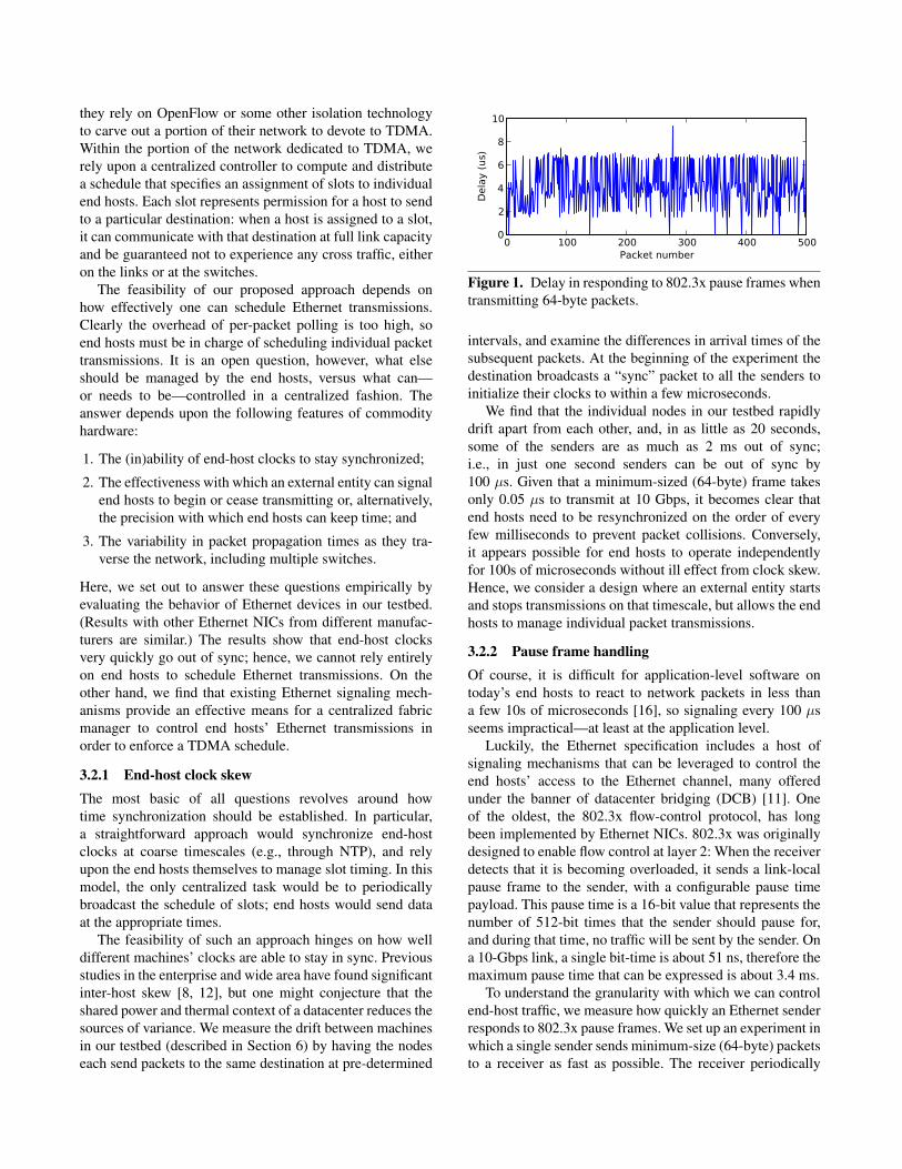
Figure 1. Delay in responding to 802.3x pause frames when
transmitting 64-byte packets.
intervals, and examine the differences in arrival times of the
subsequent packets. At the beginning of the experiment the
destination broadcasts a “sync” packet to all the senders to
initialize their clocks to within a few microseconds.
We find that the individual nodes in our testbed rapidly
drift apart from each other, and, in as little as 20 seconds,
some of the senders are as much as 2 ms out of sync;
i.e., in just one second senders can be out of sync by
100 µs. Given that a minimum-sized (64-byte) frame takes
only 0.05 µs to transmit at 10 Gbps, it becomes clear that
end hosts need to be resynchronized on the order of every
few milliseconds to prevent packet collisions. Conversely,
it appears possible for end hosts to operate independently
for 100s of microseconds without ill effect from clock skew.
Hence, we consider a design where an external entity starts
and stops transmissions on that timescale, but allows the end
hosts to manage individual packet transmissions.
3.2.2 Pause frame handling
Of course, it is difficult for application-level software on
today’s end hosts to react to network packets in less than
a few 10s of microseconds [16], so signaling every 100 µs
seems impractical—at least at the application level.
Luckily, the Ethernet specification includes a host of
signaling mechanisms that can be leveraged to control the
end hosts’ access to the Ethernet channel, many offered
under the banner of datacenter bridging (DCB) [11]. One
of the oldest, the 802.3x flow-control protocol, has long
been implemented by Ethernet NICs. 802.3x was originally
designed to enable flow control at layer 2: When the receiver
detects that it is becoming overloaded, it sends a link-local
pause frame to the sender, with a configurable pause time
payload. This pause time is a 16-bit value that represents the
number of 512-bit times that the sender should pause for,
and during that time, no traffic will be sent by the sender. On
a 10-Gbps link, a single bit-time is about 51 ns, therefore the
maximum pause time that can be expressed is about 3.4 ms.
To understand the granularity with which we can control
end-host traffic, we measure how quickly an Ethernet sender
responds to 802.3x pause frames. We set up an experiment in
which a single sender sends minimum-size (64-byte) packets
to a receiver as fast as possible. The receiver periodically
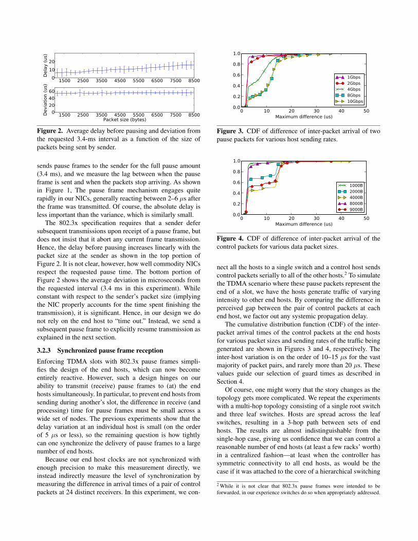
1500 2500 3500 4500 5500 6500 7500 850001020
Del
ay (u
s)
1500 2500 3500 4500 5500 6500 7500 8500Packet size (bytes)
0204060
Dev
iatio
n (u
s)
Figure 2. Average delay before pausing and deviation from
the requested 3.4-ms interval as a function of the size of
packets being sent by sender.
sends pause frames to the sender for the full pause amount
(3.4 ms), and we measure the lag between when the pause
frame is sent and when the packets stop arriving. As shown
in Figure 1, The pause frame mechanism engages quite
rapidly in our NICs, generally reacting between 2–6 µs after
the frame was transmitted. Of course, the absolute delay is
less important than the variance, which is similarly small.
The 802.3x specification requires that a sender defer
subsequent transmissions upon receipt of a pause frame, but
does not insist that it abort any current frame transmission.
Hence, the delay before pausing increases linearly with the
packet size at the sender as shown in the top portion of
Figure 2. It is not clear, however, how well commodity NICs
respect the requested pause time. The bottom portion of
Figure 2 shows the average deviation in microseconds from
the requested interval (3.4 ms in this experiment). While
constant with respect to the sender’s packet size (implying
the NIC properly accounts for the time spent finishing the
transmission), it is significant. Hence, in our design we do
not rely on the end host to “time out.” Instead, we send a
subsequent pause frame to explicitly resume transmission as
explained in the next section.
3.2.3 Synchronized pause frame reception
Enforcing TDMA slots with 802.3x pause frames simpli-
fies the design of the end hosts, which can now become
entirely reactive. However, such a design hinges on our
ability to transmit (receive) pause frames to (at) the end
hosts simultaneously. In particular, to prevent end hosts from
sending during another’s slot, the difference in receive (and
processing) time for pause frames must be small across a
wide set of nodes. The previous experiments show that the
delay variation at an individual host is small (on the order
of 5 µs or less), so the remaining question is how tightly
can one synchronize the delivery of pause frames to a large
number of end hosts.
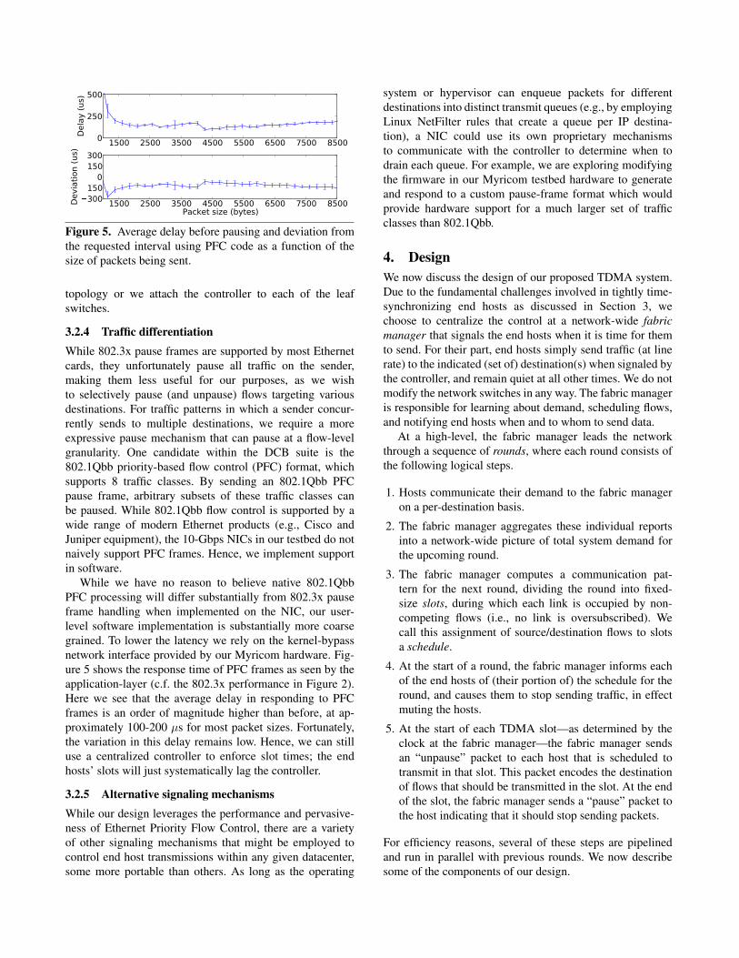
Because our end host clocks are not synchronized with
enough precision to make this measurement directly, we
instead indirectly measure the level of synchronization by
measuring the difference in arrival times of a pair of control
packets at 24 distinct receivers. In this experiment, we con-
0 10 20 30 40 50Maximum difference (us)
0.0
0.2
0.4
0.6
0.8
1.0
1Gbps2Gbps4Gbps8Gbps10Gbps
Figure 3. CDF of difference of inter-packet arrival of two
pause packets for various host sending rates.
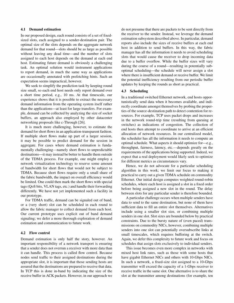
0 10 20 30 40 50Maximum difference (us)
0.0
0.2
0.4
0.6
0.8
1.0
1000B2000B4000B8000B9000B
Figure 4. CDF of difference of inter-packet arrival of the
control packets for various data packet sizes.
nect all the hosts to a single switch and a control host sends
control packets serially to all of the other hosts.2 To simulate
the TDMA scenario where these pause packets represent the
end of a slot, we have the hosts generate traffic of varying
intensity to other end hosts. By comparing the difference in
perceived gap between the pair of control packets at each
end host, we factor out any systemic propagation delay.
The cumulative distribution function (CDF) of the inter-
packet arrival times of the control packets at the end hosts
for various packet sizes and sending rates of the traffic being
generated are shown in Figures 3 and 4, respectively. The
inter-host variation is on the order of 10–15 µs for the vast
majority of packet pairs, and rarely more than 20 µs. These
values guide our selection of guard times as described in
Section 4.
Of course, one might worry that the story changes as the
topology gets more complicated. We repeat the experiments
with a multi-hop topology consisting of a single root switch
and three leaf switches. Hosts are spread across the leaf
switches, resulting in a 3-hop path between sets of end
hosts. The results are almost indistinguishable from the
single-hop case, giving us confidence that we can control a
reasonable number of end hosts (at least a few racks’ worth)
in a centralized fashion—at least when the controller has
symmetric connectivity to all end hosts, as would be the
case if it was attached to the core of a hierarchical switching
2 While it is not clear that 802.3x pause frames were intended to be
forwarded, in our experience switches do so when appropriately addressed.
1500 2500 3500 4500 5500 6500 7500 85000
250
500D
elay
(us)
1500 2500 3500 4500 5500 6500 7500 8500Packet size (bytes)
�300�150
0150300
Dev
iatio
n (u
s)
Figure 5. Average delay before pausing and deviation from
the requested interval using PFC code as a function of the
size of packets being sent.
topology or we attach the controller to each of the leaf
switches.
3.2.4 Traffic differentiation
While 802.3x pause frames are supported by most Ethernet
cards, they unfortunately pause all traffic on the sender,
making them less useful for our purposes, as we wish
to selectively pause (and unpause) flows targeting various
destinations. For traffic patterns in which a sender concur-
rently sends to multiple destinations, we require a more
expressive pause mechanism that can pause at a flow-level
granularity. One candidate within the DCB suite is the
802.1Qbb priority-based flow control (PFC) format, which
supports 8 traffic classes. By sending an 802.1Qbb PFC
pause frame, arbitrary subsets of these traffic classes can
be paused. While 802.1Qbb flow control is supported by a
wide range of modern Ethernet products (e.g., Cisco and
Juniper equipment), the 10-Gbps NICs in our testbed do not
naively support PFC frames. Hence, we implement support
in software.
While we have no reason to believe native 802.1Qbb
PFC processing will differ substantially from 802.3x pause
frame handling when implemented on the NIC, our user-
level software implementation is substantially more coarse
grained. To lower the latency we rely on the kernel-bypass
network interface provided by our Myricom hardware. Fig-
ure 5 shows the response time of PFC frames as seen by the
application-layer (c.f. the 802.3x performance in Figure 2).
Here we see that the average delay in responding to PFC
frames is an order of magnitude higher than before, at ap-
proximately 100-200 µs for most packet sizes. Fortunately,
the variation in this delay remains low. Hence, we can still
use a centralized controller to enforce slot times; the end
hosts’ slots will just systematically lag the controller.
3.2.5 Alternative signaling mechanisms
While our design leverages the performance and pervasive-
ness of Ethernet Priority Flow Control, there are a variety
of other signaling mechanisms that might be employed to
control end host transmissions within any given datacenter,
some more portable than others. As long as the operating
system or hypervisor can enqueue packets for different
destinations into distinct transmit queues (e.g., by employing
Linux NetFilter rules that create a queue per IP destina-
tion), a NIC could use its own proprietary mechanisms
to communicate with the controller to determine when to
drain each queue. For example, we are exploring modifying
the firmware in our Myricom testbed hardware to generate
and respond to a custom pause-frame format which would
provide hardware support for a much larger set of traffic
classes than 802.1Qbb.
4. Design
We now discuss the design of our proposed TDMA system.
Due to the fundamental challenges involved in tightly time-
synchronizing end hosts as discussed in Section 3, we
choose to centralize the control at a network-wide fabric
manager that signals the end hosts when it is time for them
to send. For their part, end hosts simply send traffic (at line
rate) to the indicated (set of) destination(s) when signaled by
the controller, and remain quiet at all other times. We do not
modify the network switches in any way. The fabric manager
is responsible for learning about demand, scheduling flows,
and notifying end hosts when and to whom to send data.
At a high-level, the fabric manager leads the network
through a sequence of rounds, where each round consists of
the following logical steps.
1. Hosts communicate their demand to the fabric manager
on a per-destination basis.
2. The fabric manager aggregates these individual reports
into a network-wide picture of total system demand for
the upcoming round.
3. The fabric manager computes a communication pat-
tern for the next round, dividing the round into fixed-
size slots, during which each link is occupied by non-
competing flows (i.e., no link is oversubscribed). We
call this assignment of source/destination flows to slots
a schedule.
4. At the start of a round, the fabric manager informs each
of the end hosts of (their portion of) the schedule for the
round, and causes them to stop sending traffic, in effect
muting the hosts.
5. At the start of each TDMA slot—as determined by the
clock at the fabric manager—the fabric manager sends
an “unpause” packet to each host that is scheduled to
transmit in that slot. This packet encodes the destination
of flows that should be transmitted in the slot. At the end
of the slot, the fabric manager sends a “pause” packet to
the host indicating that it should stop sending packets.
For efficiency reasons, several of these steps are pipelined
and run in parallel with previous rounds. We now describe
some of the components of our design.
4.1 Demand estimation
In our proposed design, each round consists of a set of fixed-
sized slots, each assigned to a sender-destination pair. The
optimal size of the slots depends on the aggregate network
demand for that round—slots should be as large as possible
without leaving any dead time—and the number of slots
assigned to each host depends on the demand at each end
host. Estimating future demand is obviously a challenging
task. An optimal solution would instrument applications
to report demand, in much the same way as applications
are occasionally annotated with prefetching hints. Such an
expectation seems impractical, however.
We seek to simplify the prediction task by keeping round
size small, so each end host needs only report demand over
a short time period, e.g., 10 ms. At that timescale, our
experience shows that it is possible to extract the necessary
demand information from the operating system itself rather
than the applications—at least for large transfers. For exam-
ple, demand can be collected by analyzing the size of socket
buffers, an approach also employed by other datacenter
networking proposals like c-Through [26].
It is much more challenging, however, to estimate the
demand for short flows in an application-transparent fashion.
If multiple short flows make up part of a larger session,
it may be possible to predict demand for the session in
aggregate. For cases where demand estimation is funda-
mentally challenging—namely short flows to unpredictable
destinations—it may instead be better to handle them outside
of the TDMA process. For example, one might employ a
network virtualization technology to reserve some amount
of bandwidth for short flows that would not be subject to
TDMA. Because short flows require only a small share of
the fabric bandwidth, the impact on overall efficiency would
be limited. One could then mark the short flows with special
tags (QoS bits, VLAN tags, etc.) and handle their forwarding
differently. We have not yet implemented such a facility in
our prototype.
For TDMA traffic, demand can be signaled out of band,
or a (very short) slot can be scheduled in each round to
allow the fabric manager to collect demand from each host.
Our current prototype uses explicit out of band demand
signaling; we defer a more thorough exploration of demand
estimation and communication to future work.
4.2 Flow control
Demand estimation is only half the story, however. An
important responsibility of a network transport is ensuring
that a sender does not overrun a receiver with more data than
it can handle. This process is called flow control. Because
nodes send traffic to their assigned destinations during the
appropriate slot, it is important that those sending hosts are
assured that the destinations are prepared to receive that data.
In TCP this is done in-band by indicating the size of the
receive buffer in ACK packets. However, in our approach we
do not presume that there are packets to be sent directly from
the receiver to the sender. Instead, we leverage the demand
estimation subsystem described above. In particular, demand
reports also include the sizes of receive buffers at each end
host in addition to send buffers. In this way, the fabric
manager has all the information it needs to avoid scheduling
slots that would cause the receiver to drop incoming data
due to a buffer overflow. While the buffer sizes will vary
during the course of a round—resulting in potentially sub-
optimal scheduling—the schedule will never assign a slot
where there is insufficient demand or receive buffer. We limit
the potential inefficiency resulting from our periodic buffer
updates by keeping the rounds as short as practical.
4.3 Scheduling
In a traditional switched Ethernet network, end hosts oppor-
tunistically send data when it becomes available, and indi-
rectly coordinate amongst themselves by probing the proper-
ties of the source-destination path to detect contention for re-
sources. For example, TCP uses packet drops and increases
in the network round-trip time (resulting from queuing at
switches) as indications of congestion. The collection of
end hosts then attempt to coordinate to arrive at an efficient
allocation of network resources. In our centralized model,
the scheduler has all the information it needs to compute an
optimal schedule. What aspects it should optimize for—e.g.,
throughput, fairness, latency, etc.—depends greatly on the
requirements of the applications being supported. Indeed, we
expect that a real deployment would likely seek to optimize
for different metrics as circumstances vary.
Hence, we do not advocate for a particular scheduling
algorithm in this work; we limit our focus to making it
practical to carry out a given TDMA schedule on commodity
Ethernet. Our initial design computes weighted round-robin
schedules, where each host is assigned a slot in a fixed order
before being assigned a new slot in the round. The delay
between slots for any particular sender is therefore bounded.
A particular challenge occurs when multiple senders have
data to send to the same destination, but none of them have
sufficient data to fill an entire slot themselves. Alternatives
include using a smaller slot size, or combining multiple
senders in one slot. Slot sizes are bounded below by practical
constraints. Due to the bursty nature of (even paced) trans-
missions on commodity NICs, however, combining multiple
senders into one slot can potentially oversubscribe links at
small timescales, which requires buffering at the switch.
Again, we defer this complexity to future work and focus on
schedules that assign slots exclusively to individual senders.
This issue becomes even more complex in networks with
mixed host link rates, such as those with some hosts that
have gigabit Ethernet NICs and others with 10-Gbps NICs.
In such a network, a fixed-size slot assigned to a 10-Gbps
transmitter will exceed the capacity of a 1-Gbps receiver to
receive traffic in the same slot. One alternative is to share the
slot at the transmitter among destinations (for example, ten

1-Gbps receivers). Another is to buffer traffic at the switch.
We could leverage our flow control mechanism to ensure
a switch was prepared to buffer a slot’s worth of traffic at
10 Gbps for an outgoing port, and then schedule that port
to drain the queue for the next 9 slots. We have not yet
incorporated either of these possibilities into our prototype.
4.4 Scale
Perhaps the most daunting challenge facing a centralized
design comes from the need to ensure that pause packets
from the controller arrive in close proximity at the nodes,
especially when the network can have an arbitrary topology.
In the ideal case, the fabric manager is connected to the same
switch as the hosts it controls, but such a topology obviously
constrains the size of the deployment to the number of hosts
that can be connected to a single switch. While that suffices
for, say, a single rack, multi-rack deployments would likely
require the system to function with end hosts that are
connected to disparate switches.
While the function of the scheduler is logically central-
ized, the actual implementation can of course be physically
distributed. Hence, one approach is to send pause frames
not from one fabric manager, but instead from multiple
slave controllers that are located close to the end hosts they
control, but are themselves synchronized through additional
means such as GPS-enabled NICs.
We have not yet implemented such a hierarchical design
in our prototype. Instead, we scale by employing a single
physical controller with multiple NICs that are connected
directly to distinct edge switches. Using separate threads
to send pause frames from each NIC attached to the con-
troller, we control hosts connected to each edge switch in
a manner which resembles separate slave controllers with
synchronized clocks. So far, we have tested up to 24 hosts
per switch; using our current topology and 8 NICs in a
single, centralized controller, the approach would scale to
384 hosts. Multiple such controllers which have hardware
synchronize clocks would need to be deployed to achieve
scalability to thousands of end hosts. So long as each switch
is at the same distance to the end hosts being controlled, this
approach can work for arbitrary topologies.
In a large-scale installation, these two techniques can be
combined. I.e., multiple physical controllers can coordinate
to drive a large number of hosts, where each controller is
directly connected to multiple switches. The scale of this
approach is bounded by the number of NICs a controller can
hold, the number of ports on each switch, and the ability to
tightly time synchronize each slave controller—although the
latter is easily done by connecting all the slave controllers
to a control switch and triggering the transmission of pause
frames using a link-layer broadcast frame.
SchedulerHost
handler
Demand
Control
messages
Demand
Schedule
Figure 6. The main components of the fabric manager
5. Implementation
Our prototype implementation consists of a central-
ized, multi-core fabric manager that communicates with
application-level TDMA agents at the end hosts that monitor
and communicate demand as well as schedule transmission.
Slots are coordinated through 802.1Qbb PFC pause frames.
5.1 PFC message format
Unlike the original use case for Ethernet PFC, our system
does not use these frames to pause individual flows, but
rather the converse: we pause all flows except the one(s) that
are assigned to a particular slot. Unfortunately, the priority
flow control format currently being defined in the IEEE
802.1Qbb group allows for only 8 different classes of flows.
To support our TDMA-based scheduling, one has to either
classify all the flows from a host into these 8 classes or
perform dynamic re-mapping of flows to classes within a
round. While either solution is workable, in the interest of
expediency (since we implement PFC support in software
anyway) we simply extend the PFC format to support a
larger number of classes.
In our experiments that use fewer than 8 hosts, we use the
unmodified frame format; for larger deployments we modify
the PFC format to support a 11-bit class field, rather than
the 3-bit field dictated by the 802.1Qbb specification. We
remark, however, that since the PFC frames are only acted
upon by their destination, the fabric manager can reuse PFC
classes across different nodes, as long as those classes are
not reused on the same link. Thus, the pause frame does not
need enough classes to support all the flows in the datacenter,
but rather only the flows on a single link.
5.2 Fabric manager
The fabric manager has two components as shown in Fig-
ure 6. One component is the Host Handler and other compo-
nent is Scheduler. All the tasks of interacting with the hosts
are done by the host handler while the actual scheduling
is done by the Scheduler component. The Scheduler is a
pluggable module depending on the underlying network
topology and the desired scheduling algorithm.
The fabric manager needs to be aware of both the sending
demand from each end host to calculate slot assignments, as
well as the receiving capacity to support flow control. The
role of the Host Handler is to receive the above mentioned
demand and capacity information from the end hosts and
share it with the Scheduler. End hosts send their demand
to the Host Handler out-of-band in our implementation, and
that demand is used by the Scheduler for the next round of
slot assignments. The slot assignments are sent back to the
end hosts by the Host Handler. During each round the Host
Handler sends extended PFC packet frames to each of the
end hosts to instigate the start and stop of each TDMA slot.
5.2.1 Host Handler
The Host Handler is implemented in two threads, each
pinned to their own core so as to reduce processing latency.
The first thread handles receiving demand and capacity
information from the hosts, and the second is responsible for
sending control packets to the end hosts. The actual demand
analysis is performed by the scheduler, described next.
Once the new schedule is available, a control thread sends
the pause frames to the end hosts to control the destination
to which each host sends data. The control packet destined
for each host specifies the class of traffic which the host can
send (the unpaused class). In our testbed, the fabric manager
is connected to each edge switch to reduce the variance in
sending the PFC packet frames to the end hosts. When the
pause frames are scheduled to be sent to the end hosts, the
controller sends the pause frames to the end hosts one after
the other. The pause frames are sent to all the hosts under a
switch before moving on to the next switch. The order of the
switches and the order of hosts under a switch changes in a
round robin fashion.
5.2.2 Scheduler
The scheduler identifies the flows that are going to be
scheduled in each slot. It does this with the goal of achieving
high overall bandwidth and fairness among hosts with the
constraint that no two source-destination flows use the same
link at the same time. This ensures that each sender has
unrestricted access to its own network path for the duration
of the slot. The scheduler updates the demand state infor-
mation whenever it receives demand information from the
Host Handler and periodically computes the schedule and
forwards it back to the Host Handler. The scheduler is plug-
gable, supporting different implementations. It is invoked
for each round, parameterized with the current demand and
capacity information obtained during the previous set of
rounds.
In our implementation we employ a round-robin sched-
uler that leverages some simplifying assumptions about
common network topologies (namely that they are trees) in
order to compute the schedule for the next round during
the current round. The computational complexity of this
task scales as a function of both the size of the network
and the communication pattern between the hosts. At some
point, the time required to collect demand and compute the
next schedule may become a limiting factor for round size.
Developing a scheduler that can compute a schedule for
arbitrary topologies in an efficient manner remains an open
problem.
5.3 End hosts
As discussed previously, the NICs in our experimental
testbed do not naively support PFC, and thus we handle these
control packets at user-level. We rely on a kernel-bypass,
user-level NIC firmware to reduce latency on processing
PFC packets by eliminating the kernel overhead. We are able
to read packets off the wire and process them in user space
in about 5 µs.
5.3.1 End-host controller
We separate the implementation of the controller into dis-
tinct processes for control, sending and receiving. This is
based on our observation that the responsiveness of the
control system to control packets has greater variance if the
sending and receiving is done in the same process using
separate threads. This was true even if we pinned the threads
to separate cores. Thus, our implementation has the separate
processes implementing our service communicate through
shared memory. The control packets arriving at the end
hosts specify which class of traffic (e.g., source-destination
pair) should be sent during a slot. Hosts receive the flow-
to-priority class mapping out of band. The control process
handles the PFC message and informs the sending process
of the destination to which data can be sent.
5.3.2 Sender and receiver
The sending process sends data to the appropriate destina-
tion during the assigned slot. If this host is not scheduled in
a particular slot then the sending process remains quiescent.
To simplify sending applications, we present an API similar
to TCP in that it copies data from the application into a send
buffer. This buffer is drained when the sending process gets
a slot assignment and sent to the destination as raw Ethernet
frames. We use indexed queues so that performing these data
transfers are constant-time operations. The receiving process
receives the incoming data and copies the data into receive
buffers. The application then reads the data from the receive
buffer pool through a corresponding API. As before, these
are constant time operations.
5.4 Guard times
As detailed in Section 3.2, end host timing and pause frame
processing is far from perfect. Moreover, at high overall
network utilization, small variances in packet arrival times
can cause some in-network switch buffering, resulting in in-
band control packets getting delayed, which further reduces
the precision of our signaling protocol. We mitigate this phe-
nomenon by introducing guard times between slots. These
are “safety buffers” that ensure that small discrepancies in
synchronization do not cause slot boundaries to be violated.
We have empirically determined (based largely on the
experiments in Section 3.2) on our testbed hardware that that
a guard time of 15 µs is sufficient to separate slots. This
guard time is independent of the slot time and depends on
the variance in the control packet processing time at the hosts
and the in-network buffer lengths. The cost of the guard time
is of course best amortized by introducing large slot times;
however, there is a trade-off between the slot time and how
well dynamic traffic changes are supported.
We implement guard times by first sending a pause frame
to stop all the flows in the network followed 15 µs later
by the PFC packet frame that unpauses the appropriate
traffic class at each host for the next slot. The 15-µs pause
in the system is enough to absorb variances in end host
transmission timing and drain any in-network buffers; hence,
our PFC frames reach the hosts with greater precision.
6. Evaluation
We now evaluate our TDMA-based system in several scenar-
ios on a modest-sized testbed consisting of quad-core Xeon
servers running Linux 2.6.32.8 outfitted with two 10GE
Myricom NICs. The hosts are connected together using
Cisco Nexus 5000 series switches in varying topologies as
described below. In summary, our prototype TDMA scheme
1) achieves about 15% shorter finish times than TCP for
all-to-all transfers in different topologies, 2) can achieve
3× lower RTTs for small flows (e.g., Partition/Aggregate
workloads) in the presence of long data transfers, 3) achieves
higher throughput for transfer patterns where lack of co-
ordination between the flows dramatically hurts TCP per-
formance, and 4) can improve TCP performance in rapidly
changing network topologies.
6.1 All-to-all transfer
First, we consider the time it takes to do an all-to-all transfer
(i.e., the MapReduce shuffle) in different topologies. Due do
the lack of coordination between TCP flows without TDMA,
some flows finish ahead of others. This can be problematic
in situations when progress cannot be made until all the
transfers are complete.
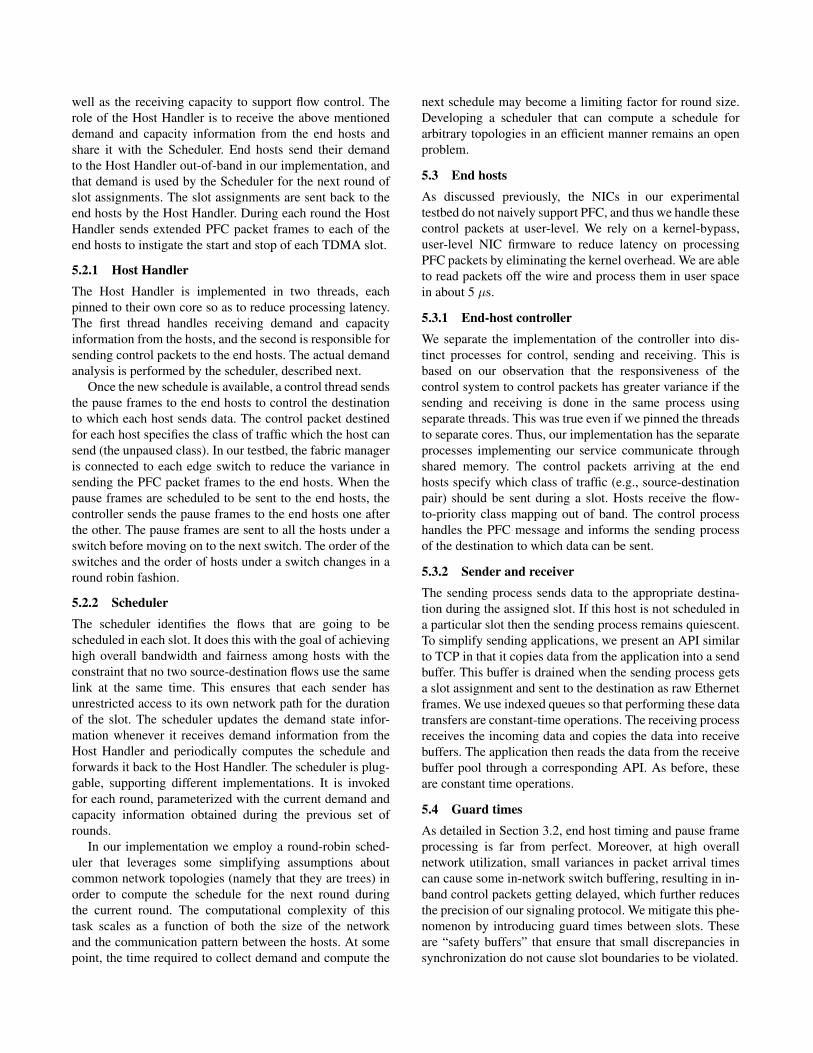
6.1.1 Non-blocking topology
In our first all-to-all transfer experiment, we connect 24
hosts to the same switch and transfer 10 GB to each other.
Ideally, such a transfer would finish in 184 seconds. The top
portion of Figure 7 shows the performance of a TCP all-to-
all transfer in this set up. The figure plots the progress of
each flow with time. We see that some flows finish early at
the expense of other flows, and, hence, the overall transfer
takes substantially more time than necessary, completing in
225 seconds.
Contrast that with bottom portion of Figure 7, which
similarly plots the progress of the hosts while running
our TDMA prototype. Due to the limitation of our end
0 50 100 150 200Time (sec)
0
2
4
6
8
10
Dat
a re
ceiv
ed (G
B)
0 50 100 150 200Time (sec)
0
2
4
6
8
10
Dat
a re
ceiv
ed (G
B)
Figure 7. 10-GB all-to-all transfer between 24 hosts con-
nected to the same switch. TCP over regular Ethernet takes
225s (top) to finish while the TDMA based system takes
194s to finish (bottom).
host networking stack, we do not use a TCP stack in our
experiments. Instead, raw Ethernet frames are transferred
between the end hosts. The TDMA system employs an
empirically chosen slot time of 300 µs (and guard times of
15µs). The finish time of the overall transfer of the same size,
194 seconds, is about 15% better than the corresponding
TCP finish time and only 5% slower than ideal (due almost
entirely to the guard band). The better finish time is achieved
by ensuring that the flows are well coordinated and finish at
the same time effectively using the available bandwidth.
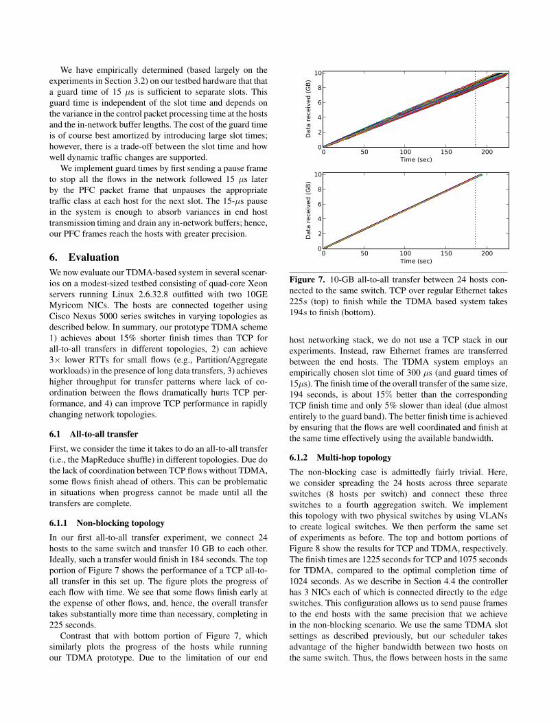
6.1.2 Multi-hop topology
The non-blocking case is admittedly fairly trivial. Here,
we consider spreading the 24 hosts across three separate
switches (8 hosts per switch) and connect these three
switches to a fourth aggregation switch. We implement
this topology with two physical switches by using VLANs
to create logical switches. We then perform the same set
of experiments as before. The top and bottom portions of
Figure 8 show the results for TCP and TDMA, respectively.
The finish times are 1225 seconds for TCP and 1075 seconds
for TDMA, compared to the optimal completion time of
1024 seconds. As we describe in Section 4.4 the controller
has 3 NICs each of which is connected directly to the edge
switches. This configuration allows us to send pause frames
to the end hosts with the same precision that we achieve
in the non-blocking scenario. We use the same TDMA slot
settings as described previously, but our scheduler takes
advantage of the higher bandwidth between two hosts on
the same switch. Thus, the flows between hosts in the same
0 200 400 600 800 1000 1200Time (sec)
0
2
4
6
8
10D
ata
rece
ived
(GB)
0 200 400 600 800 1000 1200Time (sec)
0
2
4
6
8
10
Data
rece
ived
(GB)
Figure 8. 10-GB all-to-all transfer between 24 hosts in a
tree topology. TCP over regular Ethernet takes 1225s (top)
to finish while the TDMA based system takes 1075s to finish
(bottom).
0 20 40 60 80 100 120 140Packet number
0
100
200
300
400
500
600
RTT
(us)
TCP Baseline TDMA
Figure 9. Hosts in the TDMA system have a 3x lower RTT
than hosts in the presence of other TCP flows
switch finish earlier than the flows that go across switches,
just as with TCP.
6.2 Managing delay
In a TDMA based system, the send times of hosts are
controlled by a central manager. But, when the hosts get to
send data they have unrestricted access to the network. This
should mean that when a host has access to the channel it
should experience very low latency to the destination host
even in the presence of other large flows (that are assigned
other slots). On the other hand, in a typical datacenter
environment, TCP flows occupy the buffers in the switches
increasing the latency for short flows—a key challenge
facing applications that use the Partition/Aggregate model
and require dependably low latency.
To illustrate this, we show that in the presence of long-
lived TCP flows the RTT between hosts increases. We use
0 20 40 60 80 100Waiting time (us)
05
10152025303540
RTT
(us)
Figure 10. RTT between two hosts as a function of the time
in the round when the ping is sent
the same 24-node, four-switch tree topology as before. We
call the hosts connected to each of the edge switches a pod. A
host each in pod 0 and pod 2 sends a long-lived TCP flow to a
host in pod 1. While these flows are present we send a UDP-
based ping from a host in pod 0 to a different host in pod 1.
The host which receives the ping immediately responds and
we measure the RTT between the hosts. This RTT is shown
with the TCP line in Figure 9. As expected, the RTT is high
and variable due to the queue occupancy at the switch caused
by the TCP cross traffic.
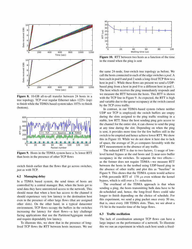
In contrast, in our TDMA-based system (where neither
UDP nor TCP is employed) the switch buffers are empty
during the slots assigned to the ping traffic resulting in a
stable, low RTT. Since the host sending ping gets access to
the channel for the entire slot, it can choose to send the ping
at any time during the slot. Depending on when the ping
is sent, it provides more time for the few buffers still in the
switch to be emptied and hence achieve lower RTT. We show
this in Figure 10. While we do not show it here due to lack
of space, the average of 26 µs compares favorably with the
RTT measurement in the absence of any traffic.
The reduced RTT is due to two factors, 1) usage of low-
level kernel bypass at the end hosts and 2) near-zero buffer
occupancy in the switches. To separate the two effects—
as the former does not require TDMA—we measure RTT
between the hosts in the testbed using UDP-based ping in
the absence of other traffic and plot this as “baseline” in
Figure 9. This shows that the TDMA system would achieve
a 95th percentile RTT of 170 µs even without the kernel
bypass, which is still over a 3× reduction.
The overhead of the TDMA approach is that when
sending a ping, the hosts transmitting bulk data have to be
de-scheduled and, hence, the long-lived flows could take
longer to finish depending on the choice of schedule. For
this experiment, we send a ping packet once every 30 ms,
that is, once every 100 TDMA slots. Thus, we see about a
1% hit in the transfer time of the large flows.
6.3 Traffic oscillation
The lack of coordination amongst TCP flows can have a
large impact on the performance of a network. To illustrate
this we run an experiment in which each host sends a fixed-
100 101 102 103 104 105 106
Transfer size (KB)
0
2
4
6
8
10Th
roug
hput
(Gbp
s)
TCPTDMA
Figure 11. Throughput of the TCP system and TDMA
system for round robin transfers with varying unit transfer
size
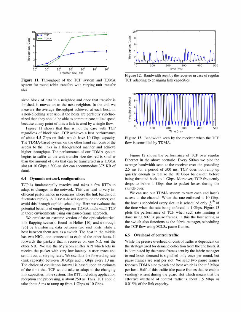
sized block of data to a neighbor and once that transfer is
finished, it moves on to the next neighbor. In the end we
measure the average throughput achieved at each host. In
a non-blocking scenario, if the hosts are perfectly synchro-
nized then they should be able to communicate at link speed
because at any point of time a link is used by a single flow.
Figure 11 shows that this is not the case with TCP
regardless of block size. TCP achieves a best performance
of about 4.5 Gbps on links which have 10 Gbps capacity.
The TDMA-based system on the other hand can control the
access to the links in a fine-grained manner and achieve
higher throughput. The performance of our TDMA system
begins to suffer as the unit transfer size desired is smaller
than the amount of data that can be transferred in a TDMA
slot (at 10 Gbps a 300-µs slot can accommodate 375 KB of
data).
6.4 Dynamic network configurations
TCP is fundamentally reactive and takes a few RTTs to
adapt to changes in the network. This can lead to very in-
efficient performance in scenarios where the link bandwidth
fluctuates rapidly. A TDMA-based system, on the other, can
avoid this through explicit scheduling. Here we evaluate the
potential benefits of employing our TDMA underneath TCP
in these environments using our pause-frame approach.
We emulate an extreme version of the optical/electrical
link flapping scenario found in Helios [10] and c-through
[26] by transferring data between two end hosts while a
host between them acts as a switch. The host in the middle
has two NICs, one connected to each of the other hosts. It
forwards the packets that it receives on one NIC out the
other NIC. We use the Myricom sniffer API which lets us
receive the packet with very low latency in user space and
send it out at varying rates. We oscillate the forwarding rate
(link capacity) between 10 Gbps and 1 Gbps every 10 ms.
The choice of oscillation interval is based upon an estimate
of the time that TCP would take to adapt to the changing
link capacities in the system: The RTT, including application
reception and processing, is about 250 µs. Thus, TCP should
take about 8 ms to ramp up from 1 Gbps to 10 Gbps.
0 100 200 300 400 500Time (ms)
0
2
4
6
8
10
Thro
ughp
ut (G
bps)
Figure 12. Bandwidth seen by the receiver in case of regular
TCP adapting to changing link capacities.
0 100 200 300 400 500Time (ms)
0
2
4
6
8
10
Thro
ughp
ut (G
bps)
Figure 13. Bandwidth seen by the receiver when the TCP
flow is controlled by TDMA.
Figure 12 shows the performance of TCP over regular
Ethernet in the above scenario. Every 500µs we plot the
average bandwidth seen at the receiver over the preceding
2.5 ms for a period of 500 ms. TCP does not ramp up
quickly enough to realize the 10 Gbps bandwidth before
being throttled back to 1 Gbps. Moreover, TCP frequently
drops to below 1 Gbps due to packet losses during the
switch-over.
We can use our TDMA system to vary each end host’s
access to the channel. When the rate enforced is 10 Gbps
the host is scheduled every slot; it is scheduled only 1
10
thof
the time when the rate being enforced is 1 Gbps. Figure 13
plots the performance of TCP when such rate limiting is
done using 802.3x pause frames. In this the host acting as
the switch also functions as the fabric manager, scheduling
the TCP flow using 802.3x pause frames.
6.5 Overhead of control traffic
While the precise overhead of control traffic is dependent on
the strategy used for demand collection from the end hosts, it
is dominated by the pause frames sent by the fabric manager
to end hosts–demand is signalled only once per round, but
pause frames are sent per slot. We send two pause frames
for each TDMA slot to each end host which is about 3 Mbps
per host. Half of this traffic (the pause frames that re-enable
sending) is sent during the guard slot which means that the
effective overhead of control traffic is about 1.5 Mbps or
0.015% of the link capacity.
7. Conclusion and future work
In this work, we propose to adapt an old approach to a new
domain by deploying a TDMA-based MAC layer across
an Ethernet datacenter network. Our approach, which does
not require changes to network switches, relies on using
link-layer flow control protocols to explicitly signal end
hosts when to send packets. Our initial results show that
the reduced in-network queuing and contention for buffer
resources result in better performance for all-to-all trans-
fer workloads and lower latency for request-response type
workloads. Significant work remains, however, to evaluate
how effectively a centralized scheduler can estimate demand
and compute efficient slot assignments for real applications
on arbitrary topologies. For example, we expect that some
workloads–particularly those made up of unpredictable short
flows, may be better serviced outside of the TDMA process.
Moreover, while our system architecture should, in princi-
ple, allow the scheduler to react to switch, node, and link
failures, we defer the evaluation of such a system to future
work.
Acknowledgments
This work was funded in part by the National Science
Foundation through grants CNS-0917339, CNS-0923523,
and ERC-0812072. Portions of our experimental testbed
were generously donated by Myricom and Cisco. We thank
the anonymous reviewers and our shepherd, Jon Crowcroft,
for their detailed feedback which helped us significantly
improve the paper.
References
[1] J. A. Alegre, J. V. Sala, S. Peres, and J. Vila. RTL-TEP: An
Ethernet protocol based on TDMA. In M. L. Chavez, editor,
Fieldbus Systems and Their Applications 2005: Proceedings
of the 6th IFAC International Conference, Nov. 2005.
[2] M. Alizadeh, A. Greenberg, D. A. Maltz, J. Padhye, P. Patel,
B. Prabhakar, S. Sengupta, and M. Sridharan. Data center TCP
(DCTCP). In ACM SIGCOMM, pages 63–74, Aug. 2010.
[3] A. Bavier, N. Feamster, M. Huang, L. Peterson, and J. Rex-
ford. In VINI veritas: realistic and controlled network experi-
mentation. ACM SIGCOMM, pages 3–14, Sept. 2006.
[4] H. H. Bazzaz, M. Tewari, G. Wang, G. Porter, T. S. E. Ng,
D. G. Andersen, M. Kaminsky, M. A. Kozuch, and A. Vahdat.
Switching the optical divide: Fundamental challenges for
hybrid electrical/optical datacenter networks. In ACM SOCC,
Oct. 2011.
[5] R. Braden, D. Clark, and S. Shenker. Integrated Services in
the Internet Architecture: an Overview. RFC 1633, June 1994.
[6] F. Chang, J. Dean, S. Ghemawat, W. C. Hsieh, D. A. Wallach,
M. Burrows, T. Chandra, A. Fikes, and R. E. Gruber. Bigtable:
A Distributed Storage System for Structured Data. ACM
Trans. Comput. Syst., 26:4:1–4:26, June 2008.
[7] Y. Chen, R. Griffith, J. Liu, R. H. Katz, and A. D. Joseph.
Understanding TCP incast throughput collapse in datacenter
networks. In WREN, pages 73–82, 2009.
[8] Y.-C. Cheng, J. Bellardo, P. Benko, A. C. Snoeren, G. M.
Voelker, and S. Savage. Jigsaw: Solving the puzzle of
enterprise 802.11 analysis. In ACM SIGCOMM, Sept. 2006.
[9] J. Dean and S. Ghemawat. MapReduce: simplified data
processing on large clusters. In USENIX OSDI, Dec. 2004.
[10] N. Farrington, G. Porter, S. Radhakrishnan, H. H. Bazzaz,
V. Subramanya, Y. Fainman, G. Papen, and A. Vahdat. Helios:
a hybrid electrical/optical switch architecture for modular data
centers. In ACM SIGCOMM, pages 339–350, Aug. 2010.
[11] Juniper Networks. Opportunities and challenges with the
convergence of data center networks. Technical report, 2011.
[12] T. Kohno, A. Brodio, and kc claffy. Remote Physical Device
Fingerprinting. In Proceedings of the IEEE Symposium and
Security and Privacy, Oakland, CA, May 2005.
[13] H. Kopetz, A. Ademaj, P. Grillinger, and K. Steinhammer. The
time-triggered Ethernet (TTE) design. In IEEE Int’l Symp. on
Object-oriented Real-time Distributed Comp., May 2005.
[14] T. Koponen, M. Casado, N. Gude, J. Stribling, L. Poutievski,
M. Zhu, R. Ramanathan, Y. Iwata, H. Inoue, T. Hama, and
S. Shenker. Onix: a distributed control platform for large-scale
production networks. USENIX OSDI, Oct. 2010.
[15] Nistica, Inc. http://www.nistica.com/.
[16] D. Ongaro, S. M. Rumble, R. Stutsman, J. Ousterhout, and
M. Rosenblum. Fast crash recovery in RAMCloud. In ACM
SOSP, pages 29–41, Oct. 2012.
[17] OpenFlow. http://www.openflow.org.
[18] J. Ousterhout, P. Agrawal, D. Erickson, C. Kozyrakis, J. Lev-
erich, D. Mazieres, S. Mitra, A. Narayanan, G. Parulkar,
M. Rosenblum, S. M. Rumble, E. Stratmann, and R. Stutsman.
The case for RAMClouds: Scalable high-performance storage
entirely in DRAM. ACM SIGOPS OSR, 43(4), Dec. 2009.
[19] P. Pedreiras, L. Almeida, and P. Gai. The FTT-Ethernet
protocol: Merging flexibility, timeliness and efficiency. In
Euromicro Conference on Real-Time Systems, June 2002.
[20] A. Phanishayee, E. Krevat, V. Vasudevan, D. G. Andersen,
G. R. Ganger, G. A. Gibson, and S. Seshan. Measurement and
analysis of TCP throughput collapse in cluster-based storage
systems. USENIX FAST, Feb. 2008.
[21] A. Rasmussen, G. Porter, M. Conley, H. V. Madhyastha, R. N.
Mysore, A. Pucher, and A. Vahdat. Tritonsort: A balanced
large-scale sorting system. In USENIX NSDI, Mar. 2011.
[22] J. Rothschild. High performance at massive scale lessons
learned at facebook. http://video-jsoe.ucsd.edu/
asx/JeffRothschildFacebook.asx, Oct. 2009.
[23] R. Santos, A. Vieira, P. Pedreiras, A. Oliveira, L. Almeida,
R. Marau, and T. Nolte. Flexible, efficient and robust real-
time communication with server-based Ethernet switching. In
IEEE Workshop on Factory Comm. Systems, May 2010.
[24] A. Singla, A. Singh, K. Ramachandran, L. Xu, and Y. Zhang.
Proteus: a topology malleable data center network. In ACM
HotNets, Oct. 2010.
[25] V. Vasudevan, A. Phanishayee, H. Shah, E. Krevat, D. G.
Andersen, G. R. Ganger, G. A. Gibson, and B. Mueller. Safe
and effective fine-grained TCP retransmissions for datacenter

communication. In ACM SIGCOMM, pages 303–314, Aug.
2009.
[26] G. Wang, D. G. Andersen, M. Kaminsky, K. Papagiannaki,
T. E. Ng, M. Kozuch, and M. Ryan. c-Through: part-time
optics in data centers. In ACM SIGCOMM, Aug. 2010.
[27] K. Webb, A. C. Snoeren, and K. Yocum. Topology switching
for data center networks. In USENIX Hot-ICE, Mar. 2011.
[28] H. Wu, Z. Feng, C. Guo, and Y. Zhang. ICTCP: Incast
congestion control for TCP in data center networks. In ACM
CoNEXT, Dec. 2010.
[29] Scaling Hadoop to 4000 nodes at Yahoo! http:
//developer.yahoo.net/blogs/hadoop/2008/
09/scaling_hadoop_to_4000_nodes_a.html.
[30] L. Zhang, S. Deering, D. Estrin, S. Shenker, and D. Zappala.
RSVP: A new resource reservation protocol. IEEE Communi-
cations, 40(5):116 –127, May 2002.