Practical Significance of DFDs Many older information systems (legacy systems): Are...
41
Practical Significance of DFDs Many older information systems (legacy systems): Are mainframe-based (inaccessible to most non-IT users); Use non-relational (hierarchical) databases, and Require second-generation programming languages (e.g. COBOL) to perform data input, queries, reporting. Thus, many IT professionals focus on data flows and physical implementation, not data relationships or RDBM design principles. Many business processes are so complex that E- R design alone will not give analysts insight into their businesses 1 DFDs allow the analyst to determine: What does the organization do? How does the organization do it?
-
Upload
thomas-morris -
Category
Documents
-
view
216 -
download
0
Transcript of Practical Significance of DFDs Many older information systems (legacy systems): Are...

Practical Significance of DFDs Many older information systems (legacy systems):
Are mainframe-based (inaccessible to most non-IT users); Use non-relational (hierarchical) databases, and Require second-generation programming languages (e.g.
COBOL) to perform data input, queries, reporting.
Thus, many IT professionals focus on data flows and physical implementation, not data relationships or RDBM design principles.
Many business processes are so complex that E-R design alone will not give analysts insight into their businesses
1
DFDs allow the analyst to determine: What does the organization do? How does the organization do it?

Creating DFDs
2
Define Entities • External entities represent
persons, processes or machines which produce data to be used by the system or receive data that is output by the system
• Examples: Student, Customer, Client
Define Processes• Processes are discrete actions
that transform input data to output data
• Examples: Create Student Record, Calculate Purchase Cost, Register Client
Student
2.1
Create Student Record

Creating DFDs (cont’d)Define Data Stores
• Data stores are temporary or permanent repositories of information that are inputs to or outputs of processes
• Examples: Student Master, Client List
Define Data Flows• Data flows represent the
transfer of data over time from one “place” (entity, process, data store) to another
• Examples: New Student Information (from Student, to Student Master)
3
New Student Information
Student Master
D3

Creating DFDs (cont’d)Define the System
• A system is the collection of all business processes which perform tasks or produce outputs we care about. It is “what happens.”
• The system is a single process, connected to external entities
• Represented in a “Context Diagram”
Define Subsystems• A subsystem gives a more
detailed view individual processes contained in the context diagram
• Includes data stores, more elementary processes
4
(Figure 4.13, Shelly, Cashman and Rosenblatt)

DFDs Created by Top-Down Analysis
Create a narrative: description of system
Create a Context Diagram that contains a single process (“the system”) and all entities which share data with the system
Explode the “parent” context diagram to produce a Diagram 0 (“child”) DFD
Create Diagram 1, 2, …, n DFDs that represent “explosions” of Diagram 0, 1, …, n-1 DFDs until a diagram has only “primitive” processes
Create process descriptions to be implemented by application programs: queries, macros, reports, programming languages
5
Context Diagram
Diagram 0 DFD
Diagram 1 DFDs
Diagram n DFDs
Narrative
E-R Diagram Process Descriptions

Where to Begin Creating DFDs
Start with the data flow from an external entity and work forwards
Start with the data flow to an external entity and work backwards
Examine the data flows into or out of a data store
Examine data flows, entity connections and data stores associated with a particular process
Note fuzzy, ill-defined areas of the system for further clarification
6

What to Avoid in DFDs
Making the data flow diagram too cluttered (e.g. 9 processes)
7
4
Perform Repair
Processes with no outputs or no inputs
1 2 3Many processes with a single input and output (linear flow)
Processes whose inputs are obviously inadequate to yield
outputs
Having data flows terminate at data stores
Connecting data stores directly to each other
Courses StudentsClass List
Connecting entities to anything other than processes
Payroll Department
Employees
Process A
Process B
Process C

DFD Example: Bus Garage RepairsBuses come to a garage for repairs.
A mechanic and helper perform the repair, record the reason for the repair and record the total cost of all parts used on a Shop Repair Order.
Information on labor, parts and repair outcome is used for billing by the Accounting Department, parts monitoring by the inventory management computer system and a performance review by the supervisor.
Key process (“the system”): performing repairs and storing information related to repairs
External Entities: Bus, Mechanic, Helper, Supervisor, Inventory Management System, Accounting Department, etc.
Processes: Record Bus ID and reason for repair Determine parts needed Perform repair Calculate parts extended and total cost Record labor hours, cost
8
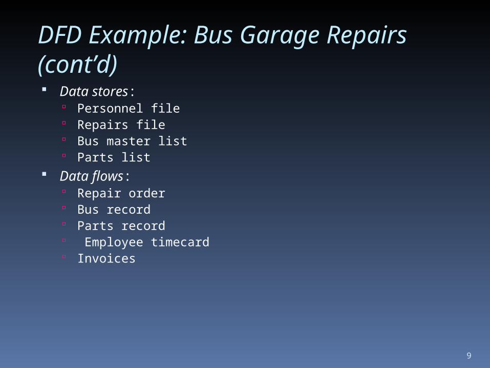
DFD Example: Bus Garage Repairs (cont’d) Data stores:
Personnel file Repairs file Bus master list Parts list
Data flows: Repair order Bus record Parts record Employee timecard Invoices
9
10
Bus
Mechanic
Helper0
Bus Repair Process
Supervisor
Accounting
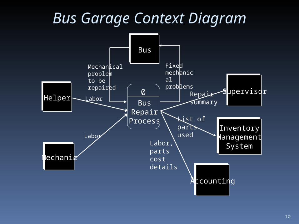
Bus Garage Context Diagram
Mechanical problem to be repaired
Labor
Labor
Fixed mechanical problems
Inventory Management
System
Repair summary
List of parts used
Labor, parts cost details
Bus Garage Diagram 0 DFD
11

Bus Garage Diagram 0 DFD (cont’d)
12

Process Modeling(Chapter 8)

Today’s Lecture Outline
Where are we? Why Process Modeling? What is Process Modeling? Basic Symbols for Process Modeling System Concept vs. Process
Decomposition Decomposition Rules Basic Concepts about a Data Flow Rules for Data Flow

Where are we?
Project ID and Selection
Project Initiation & Planning
Analysis
Logical Design
Physical Design
Implementation
Maintenance
Data ModelingProcess ModelingLogic Modeling
1. Determine system requirements
2. Structure system requirements (ch. 8-10) 3. Generate alternatives for selection

Why Process Modeling?An Information Engineering Approach
Generic IE Approach:
STUDENT
FACULTY
SECTION
COURSE
ADVISING
Student roster
Advisees Listing
Trans-cript
Processenrollment
Processregistration
AssignAdvisor
Students
Courses
SectionRegistration
DataModel
ProcessModel
InfoSystem

What is Process Modeling?
Process modeling - a technique to organize and document the system structure and data flow between system’s PROCESSES and their relevant procedures to be implemented by a system.
Data Flow Diagramming - Another logical modeling tool to
support the process modeling the second step in the Analysis stage
of SDLC
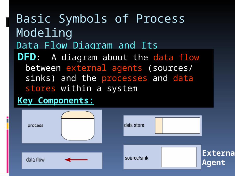
Basic Symbols of Process ModelingData Flow Diagram and Its ComponentsDFD: A diagram about the data flow
between external agents (sources/ sinks) and the processes and data stores within a system
Key Components:
ExternalAgent

An Example - A Data Flow Diagram for a Banking System

An Information System A Generic View
In general, a system could be viewed as a single Process
InformationSystem
0
Source(Customer)
Sink(Mgmt)
Trans Data
Report
You could have multiple sources and sinks!
This generic diagram is called “Context Diagram”
A Context Diagram
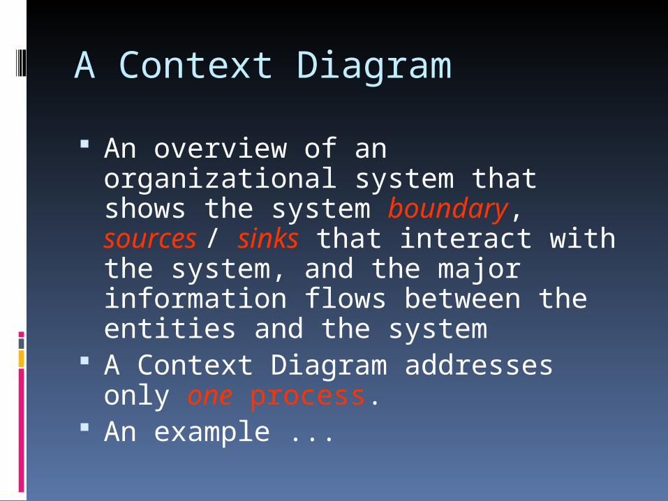
An overview of an organizational system that shows the system boundary, sources / sinks that interact with the system, and the major information flows between the entities and the system
A Context Diagram addresses only one process.
An example ...

An Example - A Context Diagram for a Fast-Food IS

A Systematic Way for Process Modeling Process Decomposition
In general, a system could be too complex to understand when viewed as a single Process
We need a Process Decomposition schemei.e., to separate a system into its subsystems (sub-processes), which in turn could be further divided into smaller subsystems until the final subsystems become manageable units (i.e., primitive processes!)
A divide and conquer strategy!!

Level-0 Diagram
A DFD that represents the primary functional processes in the system at the highest possible level
An Example ...

An Example - A decomposed Context Diagram - Level 0 Diagram

An Example - A further decompositionA Level-1 Data Flow Diagram

Process Decomposition RulesGeneric Decomposition Rules: A process in a DFD could be either a
parent process or a child process, or both.
A parent process must have two or more child processes.
A child process may further be decomposed into a set of child processes.

Decomposition Overview
Context Diagram
Level-0 Diagram

Three Major Types of Process
Function Process - A function is a set of related activities of the business (e.g., Marketing, Production, etc.)
Event Process - An event process is a logical unit of work that must be completed as a whole. (e.g., Process customer credit verification)
Primitive Process - a primitive process is a discrete, lowest-level activity/task required to complete an event. (e.g., Check the credit card balance)

Naming Rules for Processes
Function Process - use a Noun! Event Process - Use a general action
verb Process Student registration. Respond to ... Generate ...
Primitive Process - use a strong action verb Validate Student ID Check ... Calculate ...

Rules for Processes
No process can have only outputs (a miracle!)
No process can have only inputs (a black hole!)
No process can produce outputs with insufficient inputs ( a gray hole!)
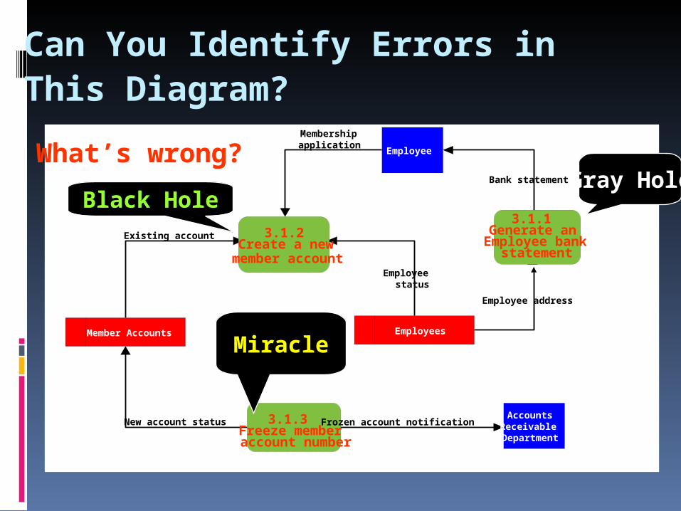
Can You Identify Errors in This Diagram?
3.1.2 Create a new
member account
3.1.1 Generate an
Employee bank statement
3.1.3 Freeze member account number
Accounts Receivable Department
Employee
Member Accounts Employees
Existing account
New account status
Employee status
Frozen account notification
Employee address
Bank statement
Membership application What’s wrong?
Black Hole
Miracle
Gray Hole

Processes in a DFDCorrect vs. Incorrect
Incorrect Correct

It has two kinds of flow: a) Inflow to a Data Store (Create/Modify/Delete) b) Outflow from a Data Store (Read)
Orders
Process Order
Cencel Order
Change Order
Address
Summarize Unfilled Orders
OrderCancelled Order
Change of Address Summary of Orders
New Order
Address
Unfilled Order
l
New Order
Order to be
Deleted
2
1
2
2
Read
Delete
Create
Modify
Basic Concept About Data Flows ...
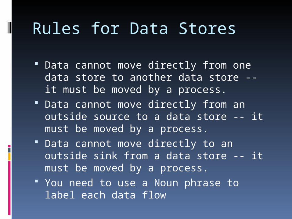
Rules for Data Stores
Data cannot move directly from one data store to another data store -- it must be moved by a process.
Data cannot move directly from an outside source to a data store -- it must be moved by a process.
Data cannot move directly to an outside sink from a data store -- it must be moved by a process.
You need to use a Noun phrase to label each data flow
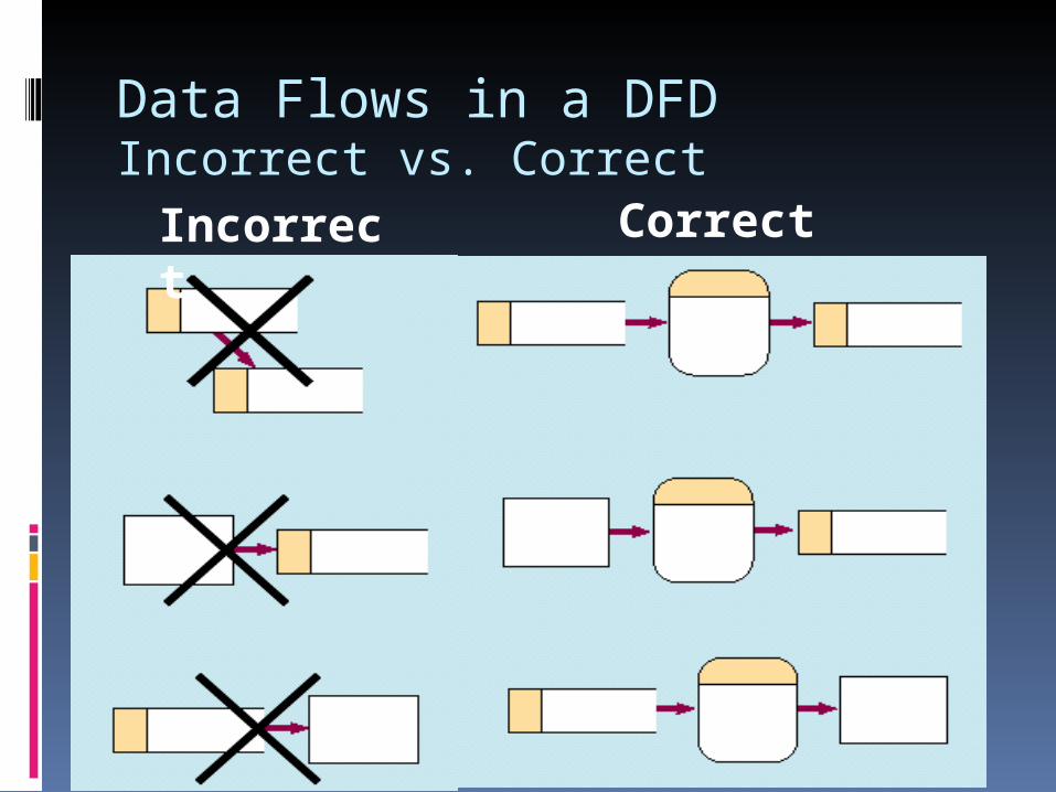
Data Flows in a DFDIncorrect vs. Correct
Incorrect Correct

Naming Rules Data Flow
Use a singular noun phrase for each data flow Ex: customer data, shipping report, …, etc.
Carry logical meaning only, i.e., no implication on data form or data structure
Minimum flow (no data flooding!!) Should never be “Unnamed!!” -
otherwise, there might be a modeling error.

Naming Scheme for Other DFD Components
Process (Event) - Use an Action Verb Phrase Process member order, Generate bank
statement, ... External Agent (Sink/Source) - Use a
singular descriptive noun Ex: Student, Customer, etc.
Data Store – Use a plural descriptive noun (Members,
Customers, etc.) Or use a noun + file (Inventory file, Goods sold
file)
Basic Rule in DFD Decomposition
Balancing Principle -- the decomposed DFD (I.e., the next lower level DFD ) should retain the same number of inputs and outputs from its previous higher level DFD (I.e., No new inputs or outputs when a DFD is decomposed)

Balancing Principle
Context Diagram
Level-0 Diagram

Unbalanced DFD