Practical Project Guide (Component selection +...
29
1 Practical Project Guide (Component selection + stuff you may encounter & need to know to complete your project) The Manufacturer’s Data Sheet …………………………………………………………………………. 2 Wires- selecting appropriate gauge ……………………………………………………………………. 3 Resistors Reading Color Codes …………………………………………………………………………….. 4 Selecting correct power Rating………………………………………………………………. 5 Potentiometers …………………………………………………………………………………………………. 6 Diodes (Semiconductor Device) ………………………………………………………………………… 7 LEDs (Semiconductor Device) …………………………………………………………………………… 8 Selecting Proper Resistance to protect an LED …………………………………………. 9 Batteries ……………………………………………………………………………………………………………. 11 Types & Comparisons…………………………………………………………………………......... 11 Capacity Ratings & Discharge Curves ……………………………………………………….. 13 Switches Types ………………………………………………………………………………………………………. 14 Uses & How to Describe ……………………………………………………………………………. 15 Capacitors Types ……………………………………………………………………………………………………… 18 Reading Codes …………………………………………………………………………………………. 18 Practical Considerations ………………………………………………………………………….. 20 Transistors Bipolar Transistors with Practical Considerations …………………………………….. 22 Using a NPN data sheet for calculations on a simple circuit ………………………… 23 Bipolar Transistor Basics & Comparison with a Relay …………………………………. 24 Programmable Unijunction Transistors (PUT) ………………….……………………….. 25 PUT Circuit Design for Pulsating Output ……………………………………………………. 25 Integrated Circuits: 555 Timer IC ………………………………………………….………………………………………… 26 Pin Id With Description …………………………………………………………………. 26 Astable Mode Circuit …………………………………………………………………….. 27 CD4017- DECADE COUNTER/DIVIDER ……………………………………………………… 28
Transcript of Practical Project Guide (Component selection +...
1
PracticalProjectGuide(Componentselection+stuffyoumayencounter&needtoknowtocompleteyourproject)
TheManufacturer’sDataSheet………………………………………………………………………….2Wires-selectingappropriategauge…………………………………………………………………….3Resistors ReadingColorCodes……………………………………………………………………………..4 SelectingcorrectpowerRating……………………………………………………………….5Potentiometers………………………………………………………………………………………………….6Diodes(SemiconductorDevice)…………………………………………………………………………7LEDs(SemiconductorDevice)……………………………………………………………………………8 SelectingProperResistancetoprotectanLED………………………………………….9Batteries…………………………………………………………………………………………………………….11 Types&Comparisons………………………………………………………………………….........11 CapacityRatings&DischargeCurves………………………………………………………..13 Switches Types……………………………………………………………………………………………………….14 Uses&HowtoDescribe…………………………………………………………………………….15Capacitors Types………………………………………………………………………………………………………18 ReadingCodes………………………………………………………………………………………….18 PracticalConsiderations…………………………………………………………………………..20Transistors BipolarTransistorswithPracticalConsiderations……………………………………..22 UsingaNPNdatasheetforcalculationsonasimplecircuit…………………………23 BipolarTransistorBasics&ComparisonwithaRelay………………………………….24 ProgrammableUnijunctionTransistors(PUT)………………….………………………..25 PUTCircuitDesignforPulsatingOutput…………………………………………………….25IntegratedCircuits: 555TimerIC………………………………………………….…………………………………………26 PinIdWithDescription………………………………………………………………….26 AstableModeCircuit……………………………………………………………………..27 CD4017-DECADECOUNTER/DIVIDER………………………………………………………28

2
THEMANUFACTUER’SDATASHEET-ONCEYOUIDTHECOMPONENT,LOOKUPITSINFORMATIONTOMAKESUREYOUHAVEAHAPPYCIRCUIT
Youcanfindallimportantinformationforanycomponentmadebyanymanufacturerbyreadingitsdatasheet.ItwillbeincludedwiththecomponentoryouwillneedtoGooglethecomponentwithitspartnumberandmanufacturer’sname.Inclassthisyear,youareresponsibleforselectingcomponentsandbuildingcircuitsthatyouwillneedtocompleteaproject.Itisimportantthatyouunderstandtheperformanceofeachcomponentgiventheoperatingconditionsitexperiencesintheactualcircuit.Forexample,youmayusetheSuperBrightRed5mmLEDssoldbyAdafruitforyourproject.WhenIGooglethecomponent,Adafruitpoststhefollowinginformation:◦ 5mmdiameter◦ 640nmwavelength◦ 1.8-2.2VForwardVoltage,at20mAcurrent◦ 1500mcdtypicalbrightness◦ ViewingAngle:±10degrees◦ Maximumcontinuouscurrent:30mASo,thatwassimple,butwhatifyouwerelookingforthe5mmSuperBrightRedLEDmadebyKingbrightwiththepartnumberWP7113SRD/D.IfyouGoogleit,youwillbeledtothefollowingwebpagehttps://cdn-shop.adafruit.com/datasheets/WP7113SRD-D.pdfHereyou’llhaveallthepossibleinfoyou’llneed.Foreachcomponentofyourcircuit,you’llneedtoknowspecificinformationinordertomakeyourcircuitworkandtomaximizeitsperformance.UsethisPRACTICALPROJECTGUIDEtohelpasyoudesignyourcircuitforthisproject.

3
1.WIRES-usedtoasapathwayfortheelectronsinthecircuit SCHEMATICforawireis________________
We’llmostlybeusing18-22AWG(AmericanWireGauge)andforourproject,theresistanceofthewireispracticallynothing(veryshortwire)ascomparedtotheresistanceofthecircuit.
*TakenfromPracticalElectronicsforInventors,4thEdition,pg253ofKindleEdition

4
*TakenfromPracticalElectronicsforInventors,4thEdition,pg254ofKindleEdition
Howtoselectthecorrectgaugeofwire?LOOKATWHATYOUWILLBEUSINGINYOURCIRCUITANDDETERMINETHEMAXIMUMCURRENTYOUNEED?
*TakenfromPracticalElectronicsforInventors,4thEdition,pg38ofKindleEdition
ThisrowofschematicsindicateconnectionsbetweenwiresThisrowofschematicsshowswiresnotconnected

5
2.Resistors-provideresistancetothecurrentandoftenusedtoprotectcomponentsbyreducingthecurrentthroughthemandcanbeusedtomakeavoltagedividingcircuit
ACOLORCHARTONHOWTOREADRESISTORCODING
SCHEMATIC-Eitherisfine
Thisrowofschematicsindicateconnectionsbetweenwires
6
SelectionofAResistor:TemperaturelimitforoperationisdeterminedbymaximumpowerakathePOWERRATING(THEHIGHERTHEPOWERRATINGTHELARGERTHERESISTOR)TodeterminewhatpowerratingforaparticularresistancetouseRULEOFTHUMB:SELECTAPOWERRATING2to4timesgreaterthatthecalculatedvalueforthatresistanceusingtheappropriatepowerequationsREADINGARESISTOR’SDATASHEET*Temperaturecanreallyaffectacircuitsoperation!
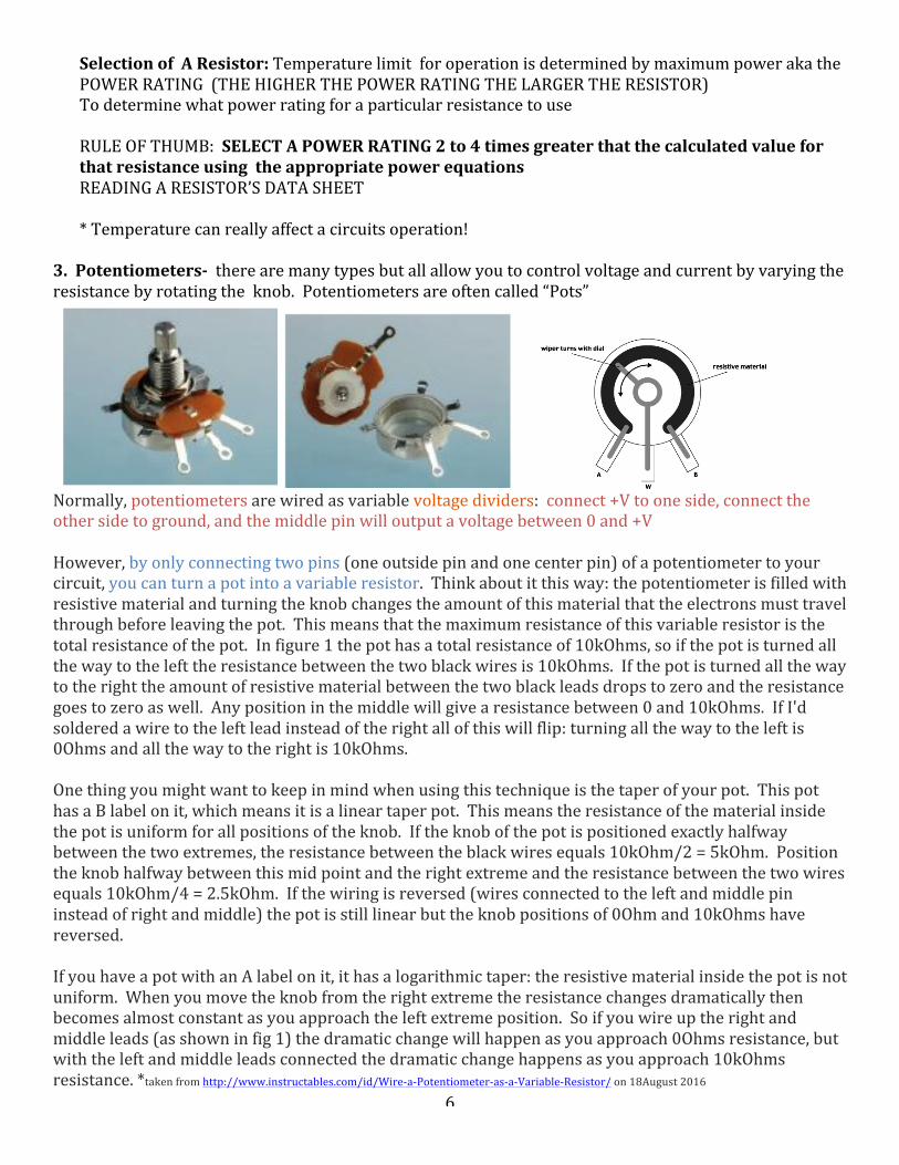
3.Potentiometers-therearemanytypesbutallallowyoutocontrolvoltageandcurrentbyvaryingtheresistancebyrotatingtheknob.Potentiometersareoftencalled“Pots”
Normally,potentiometersarewiredasvariablevoltagedividers:connect+Vtooneside,connecttheothersidetoground,andthemiddlepinwilloutputavoltagebetween0and+VHowever,byonlyconnectingtwopins(oneoutsidepinandonecenterpin)ofapotentiometertoyourcircuit,youcanturnapotintoavariableresistor.Thinkaboutitthisway:thepotentiometerisfilledwithresistivematerialandturningtheknobchangestheamountofthismaterialthattheelectronsmusttravelthroughbeforeleavingthepot.Thismeansthatthemaximumresistanceofthisvariableresistoristhetotalresistanceofthepot.Infigure1thepothasatotalresistanceof10kOhms,soifthepotisturnedallthewaytothelefttheresistancebetweenthetwoblackwiresis10kOhms.Ifthepotisturnedallthewaytotherighttheamountofresistivematerialbetweenthetwoblackleadsdropstozeroandtheresistancegoestozeroaswell.Anypositioninthemiddlewillgivearesistancebetween0and10kOhms.IfI'dsolderedawiretotheleftleadinsteadoftherightallofthiswillflip:turningallthewaytotheleftis0Ohmsandallthewaytotherightis10kOhms.Onethingyoumightwanttokeepinmindwhenusingthistechniqueisthetaperofyourpot.ThispothasaBlabelonit,whichmeansitisalineartaperpot.Thismeanstheresistanceofthematerialinsidethepotisuniformforallpositionsoftheknob.Iftheknobofthepotispositionedexactlyhalfwaybetweenthetwoextremes,theresistancebetweentheblackwiresequals10kOhm/2=5kOhm.Positiontheknobhalfwaybetweenthismidpointandtherightextremeandtheresistancebetweenthetwowiresequals10kOhm/4=2.5kOhm.Ifthewiringisreversed(wiresconnectedtotheleftandmiddlepininsteadofrightandmiddle)thepotisstilllinearbuttheknobpositionsof0Ohmand10kOhmshavereversed.IfyouhaveapotwithanAlabelonit,ithasalogarithmictaper:theresistivematerialinsidethepotisnotuniform.Whenyoumovetheknobfromtherightextremetheresistancechangesdramaticallythenbecomesalmostconstantasyouapproachtheleftextremeposition.Soifyouwireuptherightandmiddleleads(asshowninfig1)thedramaticchangewillhappenasyouapproach0Ohmsresistance,butwiththeleftandmiddleleadsconnectedthedramaticchangehappensasyouapproach10kOhmsresistance.*takenfromhttp://www.instructables.com/id/Wire-a-Potentiometer-as-a-Variable-Resistor/on18August2016
SCHEMATIC-Eitherisfine(theleftistheUSAversion&therightistheEuropeanVersion)

7
Markingsonthe“Pot”-A=LogTaper((voltageinalogrelationshipwithposition)B=LinearTaper(voltageinalinearrelationshipwithposition)IMPORTANT:DON’TEXCEEDYOURPOTSCURRENTANDVOLTAGERATING

8
4.Diodes-asemiconductingdevicethatactsasaonewaygateforelectriccurrent.Iftheanodeleadismademorepositivethanitscathodelead,thencurrentispermittedtoflowthroughthedevice(forwardbiased-needtohaveaminimumvoltagethough).Iftheanodehappenstobemorenegativeinvoltagethecathodelead,thenitactstoblockcurrentflow(reversedbiased).
CheckoutCircuit’sPlaygroundforafuncutevideoDisforDiode*Dependingonhowyouwireyourfinalcircuit,youmaywanttoincludeadiode
SCHEMATIC

9
5.LEDS-LightEmittingDiode(Veryefficientwayofcreatinglight&theylastforaverylongtimeaslongasyouaregoodtothem)
TolearnhowtoreadadatasheetforanLEDgotohttps://learn.adafruit.com/all-about-leds/the-led-datasheet
USESOFDIFFERENTDIAMETERLEDS◦ 5mmLEDscanbesobright,theyareoftenusedasillumination(lightingsomethingup)◦ 3mmLEDsarenotasbrightbutaresmaller,andaregoodforindication(likeanLEDthattellsyou
somethingison).They'renotasgoodforilluminationbecausetheyhaveasmallerareathatislit.◦ 10mmLEDsarealittlemorerare,theyarehugeandchunkybutareusuallyjust5mmLEDswitha
biggercasesotheyaren'tanybrighter.Theycanbegoodindicatorsbutwerarelyseethemasilluminators.
SCHEMATIC-Anyofthefollowingarefine!
Ø Thelongerleg(theanode)mustalwaysbemorepositivethantheshorterleg(cathode)
Ø Thevoltagedifference
betweenthelegscannotexceedthemanufacturer’slimit
Ø Thecurrentpassingthrough
theLEDcannotexceedthemanufacturer’slimit
Useamanufacture’sdatasheettofindouttheinformation

10
SelectingTheProperResistanceToUseInSeriesWithanLEDFindtheforwardvoltageratingontheLED’sdatasheet,Vfandtakeanaverageoftheminimumandmaximum.Dothesameforsuggestedusingcurrentrange.Tofindthevalueoftheresistance,subtracttheaverageforwardvoltagefromthevoltagebeingsuppliedandmultiplybytheaveragecurrentforoperation.
𝑅 = 𝑉!" − 𝑉! 𝐼IfyouhaveabunchofLEDsinseries,youonlyneedoneresistortoprotecttheLEDs,thentheequationbecomes
𝑅 = 𝑉!" − 𝑛𝑉! 𝐼wherenisthenumberofLEDs.ExampleonReadingDataSheetandselectingaresistortoprotecttheLED
*Make:WearableElectronics:Design,prototype,andwearyourowninteractivegarments,pg4KindleEdition
Vin
+
-
R

11
Let’ssayIampoweringthecircuitonthepreviouspagewith3.0v.UsingKirchhoff’sVoltageLaw-thesumofallvoltagedrops=thesumofallvoltagegains.IknowthatthevoltagedropacrosstheresistorplusthevoltagedropacrosstheLEDwhichwouldbe1.8-2.2Vaccordingtothedatasheet,solet’ssat2.0V.ThismeansthatIwillhavea1.0VoltdropacrosstheresistorandthatthecurrentgoingthroughtheresistorandtheLEDwouldneedtobe16-18maaccordingtothechart,solet’ssay17mA.Theequationofpage9isjustOhm’sLawappliedtotheresistor,so
𝑅 = (!.!!!!.!!)!.!"#!
=58.8ΩNow,lookatourcollectionofresistorstofindonethatis≥58.8Ω.Thepoweroftheresistor=IV,so0.017Ax1.0V=.017W,soa62Ω¼WattResistorwouldbefine!

12
6.Batteries-powercircuits.Therearetonsofdifferenttypesofbatteries,butthesearethemostcommon(havemostoftheseinlab)
*TakenfromPracticalElectronicsforInventors,4thEdition,pg273ofKindleEditionSCHEMATICFORA2CELLBATTERY(helonglineindicatesa“+”sideoranodeandtheshortline,the“-“sideorcathode)
Forelectroniccircuit,usingacellisOKbutnotinRegentsPhysics

13
PrimaryBatteryTypeComparisons
*TakenfromPracticalElectronicsforInventors,4thEdition,pg277ofKindleEditionTerminalVoltage:TerminalVoltageisthevoltagetheexternalcircuitseeswhenabatteryisbeingused.Allbatterieshaveinternalresistancethatbecomesapparentwhenitisusedinacircuit.VTerminal=IR=ξ –IrorI=
R + rξ whereξ =emf(markedbatteryvoltage-NominalVoltage)andr=internal
resistanceofthebattery.Whenchargingabattery:VTerm=ξ +IrNominalVoltage-The“named”voltage-willbethevoltagestampedonthebatterywithoutaload(externalcircuitonit)–closetowhatyouwouldmeasurewithavoltmeter
*TakenfromPracticalElectronicsforInventors,4thEdition,pg289ofKindleEdition

14
*TakenfromPracticalElectronicsforInventors,4thEdition,pg273ofKindleEditionBatteriescanbeconnectedinseriesorparallel-dependsonwhatyouneedandwhatisimportanttoyouBatteryCapacityRating-tellsyouhowmuchelectricalenergytheycandeliveroveraperiodoftimeandisgivenintermsofmAh(milliamphours).YoucanfigureouthowlongthebatterywilllastbydivingthepowercapacityratingbythecurrentbeingdrawnintermsofmA(milliamps)
DischargeTime=!"#$% !"#$%& !"#"$%&'!"##$%& !"#$% !"#$%
CRating-efficiencyofabatterytostoreenergy&itsabilitytotransferitsenergytoanactualload(Creferstothechargeanddischargecurrents)
DischargeTime=!"##$%& !"#"$%&' !"#$%&
! !"#$%&
BatteryCapacityRating CRating CurrentDrawn DischargeTime
1000mAhr 1 1000mA 1hr0.5 500mA 2hr2.0 2000mA 0.5hr5 5000mA 0.2hr

15
7.Switches:Switchesaremechanicaldevicesthatinterruptordivertselectricflowwithinacircuit
EXAMPLEOFSWITCHESINUSE:ASIMPLEHOMESECURITYSYSTEM CURRENTFLOWREVERSALSYSTEM
*TakenfromPracticalElectronicsforInventors,4thEdition,pg289&pg293ofKindleEdition
DUALLOCATIONON/OFFSYSTEM
Abasicswitchismadeupofapolethatconnectstoacontacttoclosethecircuit-ThisisaSinglePoleSingleThrow(SPST)Switch
16
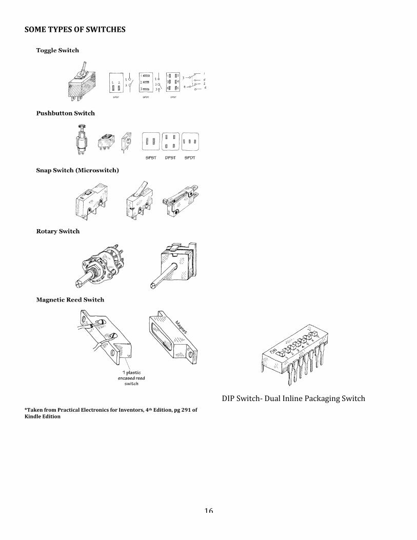
SOMETYPESOFSWITCHES
*TakenfromPracticalElectronicsforInventors,4thEdition,pg291ofKindleEdition
DIPSwitch-DualInlinePackagingSwitch

17
DESCRIBINGSWITCHES-PolesandThrows!Thefollowinginfoonswitcheswastakenfromhttps://learn.sparkfun.com/tutorials/switch-basics/poles-and-throws-open-and-closedSPST
Asingle-pole,single-throw(SPST)switchisassimpleasitgets.It’sgotoneoutputandoneinput.Theswitchwilleitherbeclosedorcompletelydisconnected.SPSTsareperfectforon-offswitching.They’realsoaverycommonformofmomentaryswitches.SPSTswitchesshouldonlyrequiretwoterminals.
ThecircuitsymbolforanSPSTswitchintheoffpositionandathrough-hole,right-angle,maintained,SPST,rockerswitch.
SPDT
Anothercommonswitch-typeistheSPDT.SPDTshavethreeterminals:onecommonpinandtwopinswhichvieforconnectiontothecommon.SPDTsaregreatforselectingbetweentwopowersources,swappinginputs,orwhateveritisyoudowithtwocircuitstryingtogooneplace.MostsimpleslideswitchesareoftheSPDTvariety.SPDTswitchesshouldusuallyhavethreeterminals.(Sidenote:inapinchanSPDTcanactuallybemadeintoanSPSTbyjustleavingoneoftheswitchthrowsunconnected).
AnSPDTswitchcircuitsymbol,andanSPDTslideswitch.
DPDT
AddinganotherpoletotheSPDTcreatesadouble-pole,double-throw(DPDT)switch.BasicallytwoSPDTswitches,whichcancontroltwoseparatecircuits,butarealwaysswitchedtogetherbyasingleactuator.DPDTsshouldhavesixterminals.
ADPDTcircuitsymbol,anda6-terminalDPDTrockerswitch.
18
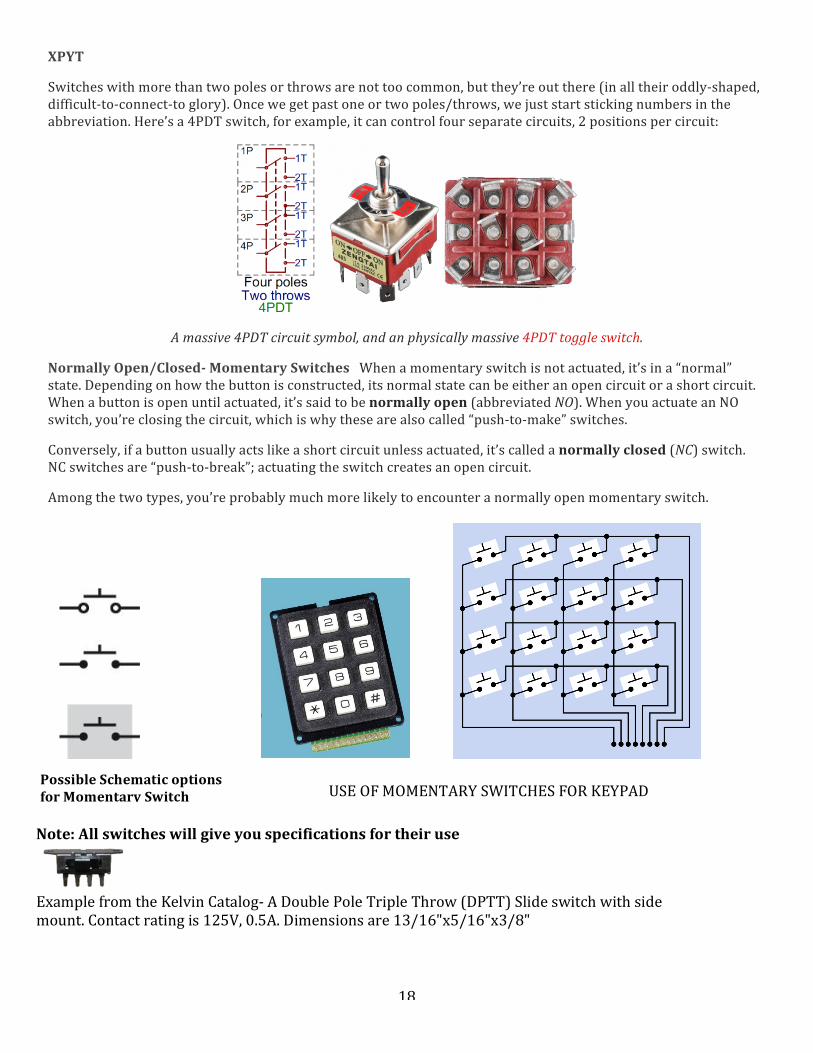
XPYT
Switcheswithmorethantwopolesorthrowsarenottoocommon,butthey’reoutthere(inalltheiroddly-shaped,difficult-to-connect-toglory).Oncewegetpastoneortwopoles/throws,wejuststartstickingnumbersintheabbreviation.Here’sa4PDTswitch,forexample,itcancontrolfourseparatecircuits,2positionspercircuit:
Amassive4PDTcircuitsymbol,andanphysicallymassive4PDTtoggleswitch.
NormallyOpen/Closed-MomentarySwitchesWhenamomentaryswitchisnotactuated,it’sina“normal”state.Dependingonhowthebuttonisconstructed,itsnormalstatecanbeeitheranopencircuitorashortcircuit.Whenabuttonisopenuntilactuated,it’ssaidtobenormallyopen(abbreviatedNO).WhenyouactuateanNOswitch,you’reclosingthecircuit,whichiswhythesearealsocalled“push-to-make”switches.
Conversely,ifabuttonusuallyactslikeashortcircuitunlessactuated,it’scalledanormallyclosed(NC)switch.NCswitchesare“push-to-break”;actuatingtheswitchcreatesanopencircuit.
Amongthetwotypes,you’reprobablymuchmorelikelytoencounteranormallyopenmomentaryswitch.
Note:Allswitcheswillgiveyouspecificationsfortheiruse
ExamplefromtheKelvinCatalog-ADoublePoleTripleThrow(DPTT)Slideswitchwithsidemount.Contactratingis125V,0.5A.Dimensionsare13/16"x5/16"x3/8"
PossibleSchematicoptionsforMomentarySwitch USEOFMOMENTARYSWITCHESFORKEYPAD
19
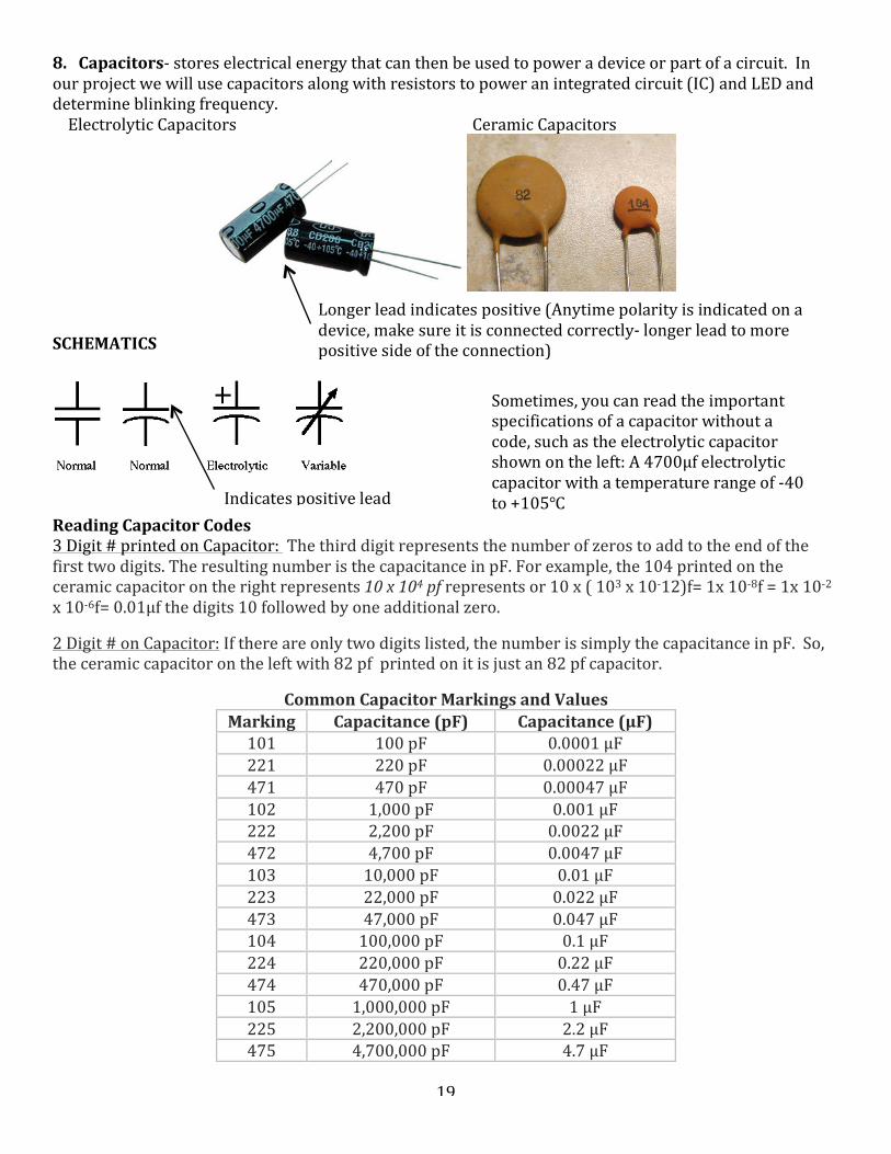
8.Capacitors-storeselectricalenergythatcanthenbeusedtopoweradeviceorpartofacircuit.Inourprojectwewillusecapacitorsalongwithresistorstopoweranintegratedcircuit(IC)andLEDanddetermineblinkingfrequency.ElectrolyticCapacitors CeramicCapacitors
SCHEMATICS
ReadingCapacitorCodes3Digit#printedonCapacitor:Thethirddigitrepresentsthenumberofzerostoaddtotheendofthefirsttwodigits.TheresultingnumberisthecapacitanceinpF.Forexample,the104printedontheceramiccapacitorontherightrepresents10x104pfrepresentsor10x(103x10-12)f=1x10⁻⁸f=1x10-2x10-6f=0.01μfthedigits10followedbyoneadditionalzero.2Digit#onCapacitor:Ifthereareonlytwodigitslisted,thenumberissimplythecapacitanceinpF.So,theceramiccapacitorontheleftwith82pfprintedonitisjustan82pfcapacitor.
CommonCapacitorMarkingsandValues
Marking Capacitance(pF) Capacitance(μF)101 100pF 0.0001μF221 220pF 0.00022μF471 470pF 0.00047μF102 1,000pF 0.001μF222 2,200pF 0.0022μF472 4,700pF 0.0047μF103 10,000pF 0.01μF223 22,000pF 0.022μF473 47,000pF 0.047μF104 100,000pF 0.1μF224 220,000pF 0.22μF474 470,000pF 0.47μF105 1,000,000pF 1μF225 2,200,000pF 2.2μF475 4,700,000pF 4.7μF
Longerleadindicatespositive(Anytimepolarityisindicatedonadevice,makesureitisconnectedcorrectly-longerleadtomorepositivesideoftheconnection)
Indicatespositivelead
Sometimes,youcanreadtheimportantspecificationsofacapacitorwithoutacode,suchastheelectrolyticcapacitorshownontheleft:A4700μfelectrolyticcapacitorwithatemperaturerangeof-40to+105℃

20
Rememberthatmcro,μ=10-6&pico,p=10-9Youmayalsoseealetterprintedonthecapacitortoindicatethetolerance.Youcaninterpretthetoleranceletterasfollows:Letter ToleranceA ±0.05pFB ±0.1pFC ±0.25pFD ±0.5pFE ±0.5%F ±1%G ±2%H ±3%J ±5%K ±10%L ±15%M ±20%N ±30%P –0%,+100%S –20%,+50%W –0%,+200%X –20%,+40%Z –20%,+80%CodesthatContainLettersasoneofthefirsttwocharacters:Therearethreepossibilities
o IftheletterisanR,thenreplaceitwithadecimalpointtogetthecapacitanceinpf.Example4R1is4.1pf.
o Iftheletterisap,n,oru,thenthistellsyoutheunitspicofarad,pf,nanofaradnf,ormicrofarad,μfo Ifyougetacodelikethis1A253,the1A,tellsyouthevoltageand253isthe3digitcapacitorcode
likeabove.MaxOperatingVoltageCodesCode Max
Voltage0J 6.3V1A 10V1C 16V1E 25V1H 50V2A 100V2D 200V2E 250V
Soforacapacitormarked1A253,Youhavea10VMaxvoltage0.025μfCapacitor
Ifyouhadacapacitormarked2E105k,thenthatwouldbea250Vmaxvoltage1μfcapacitorwithatoleranceof+/-10%

21
Letter-Number-LetterCapactitorCode*The1stsymbolgivesyoutheminimumtemperature*The2ndsymbolgivesyouthemaximumtemperature*The3rdsymbolgivesyouvariationofthecapacitanceacrossthetemperaturerange1stSymbol-minTempCode °𝐶X -55Y -30Z 102ndSymbol-MaxTempCode °𝐶2 454 655 856 1057 125
3rdSymbol-VarianceofCapacitanceoverTempRangeCode ± %A 1.0B 1.5C 2.2D 3.3E 4.7F 7.5P 10.0R 15.0S 22.0T 22to33U 22to56V 22to82
Example:AcapacitorstampedwithZ2Rwouldhaveatemperaturerangeof10to45℃withavariance incapacitanceof± 15%Thingstoconsiderwhenselectingacapacitortoplaceinacircuit(2ofthemostcommonthatwe’llbeusing)
• DCWorkingVoltage(DCWV)-maximumsafelimitofdcvoltageacrossthecapacitorbeforedielectricbreakdown
*TakenfromPracticalElectronicsforInventors,4thEdition,pg340ofKindleEdition
22
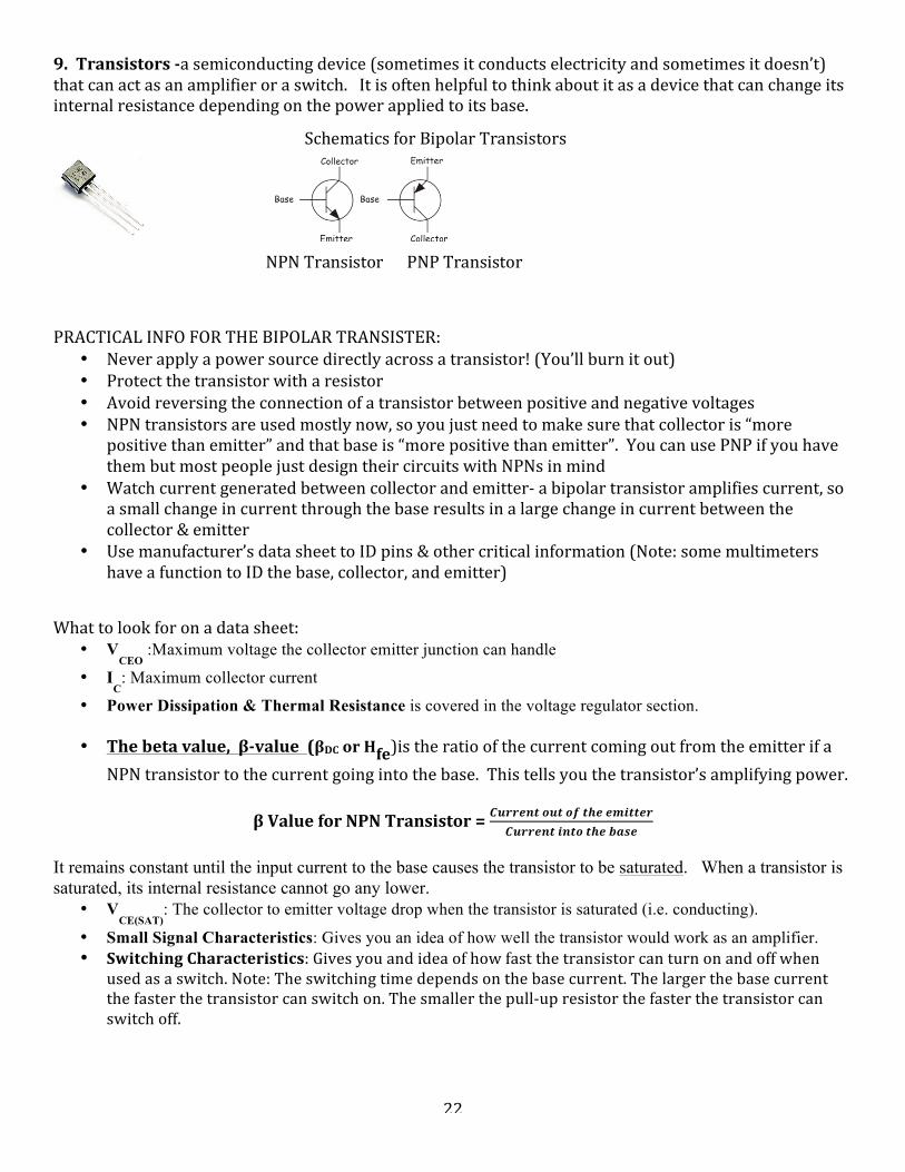
9.Transistors-asemiconductingdevice(sometimesitconductselectricityandsometimesitdoesn’t)thatcanactasanamplifieroraswitch.Itisoftenhelpfultothinkaboutitasadevicethatcanchangeitsinternalresistancedependingonthepowerappliedtoitsbase.
PRACTICALINFOFORTHEBIPOLARTRANSISTER:
• Neverapplyapowersourcedirectlyacrossatransistor!(You’llburnitout)• Protectthetransistorwitharesistor• Avoidreversingtheconnectionofatransistorbetweenpositiveandnegativevoltages• NPNtransistorsareusedmostlynow,soyoujustneedtomakesurethatcollectoris“more
positivethanemitter”andthatbaseis“morepositivethanemitter”.YoucanusePNPifyouhavethembutmostpeoplejustdesigntheircircuitswithNPNsinmind
• Watchcurrentgeneratedbetweencollectorandemitter-abipolartransistoramplifiescurrent,soasmallchangeincurrentthroughthebaseresultsinalargechangeincurrentbetweenthecollector&emitter
• Usemanufacturer’sdatasheettoIDpins&othercriticalinformation(Note:somemultimetershaveafunctiontoIDthebase,collector,andemitter)
Whattolookforonadatasheet:
• VCEO
:Maximum voltage the collector emitter junction can handle
• IC: Maximum collector current
• Power Dissipation & Thermal Resistance is covered in the voltage regulator section.
• Thebetavalue,β-value(βDCorHfe)istheratioofthecurrentcomingoutfromtheemitterifaNPNtransistortothecurrentgoingintothebase.Thistellsyouthetransistor’samplifyingpower.
βValueforNPNTransistor=𝑪𝒖𝒓𝒓𝒆𝒏𝒕 𝒐𝒖𝒕 𝒐𝒇 𝒕𝒉𝒆 𝒆𝒎𝒊𝒕𝒕𝒆𝒓
𝑪𝒖𝒓𝒓𝒆𝒏𝒕 𝒊𝒏𝒕𝒐 𝒕𝒉𝒆 𝒃𝒂𝒔𝒆
It remains constant until the input current to the base causes the transistor to be saturated. When a transistor is saturated, its internal resistance cannot go any lower.
• VCE(SAT)
: The collector to emitter voltage drop when the transistor is saturated (i.e. conducting).
• Small Signal Characteristics: Gives you an idea of how well the transistor would work as an amplifier. • SwitchingCharacteristics:Givesyouandideaofhowfastthetransistorcanturnonandoffwhen
usedasaswitch.Note:Theswitchingtimedependsonthebasecurrent.Thelargerthebasecurrentthefasterthetransistorcanswitchon.Thesmallerthepull-upresistorthefasterthetransistorcanswitchoff.
NPNTransistorPNPTransistor
SchematicsforBipolarTransistors

23
Sample circuit and calculations using a data sheet (NPN transistor): *Taken from http://www.physics.unlv.edu/~bill/PHYS483/transbas.pdf on 2nd July, 2016 Let's say we want to heat a block of metal. One way to do that is to connect a power resistor to the block and run current through the resistor. The resistor heats up and transfers some of the heat to the block of metal. We will use a transistor as a switch to control when the resistor is heating up and when it's cooling off (i.e. no current flowing in the resistor). In the circuit below R1 is the power resistor that is connected to the object to be heated.
Note: The transistor isn't a perfect switch. When off there is a small current that flows (~50nA for the 2N3904) and when on it has a small voltage drop (~0.2V depending on the collector & base currents). First calculate the collector current when the switch is on (current is allowed to flow from collector to emitter). I = V/R = (12V – 0.2V)/100Ω = 118mA. Now calculate the needed base current required to turn on the transistor. Looking at the datasheet, H
fe could be as low as 30 at 100mA. The base current should then be
IC/ H
fe = 118mA/30mA = 4mA.
We will add a factor of two for safety and use a base current of 8mA (to make sure the transistor turns on fully). Finally calculate the value for R2, the base resistor. Note: When the transistor is turned on there will be about a 0.7V drop across the base emitter junction. Therefore R2 = V/I
b = (5V – 0.75V)/8mA = 531Ω. This value isn't critical so use the closest
standard value (560Ω). That's it. When the input to the base resistor is zero (or less than about 0.65V) no base current flows and the transistor is off (i.e. no current flows through the 100Ω resistor). When the input to the base resistor is 5V the base current is 8mA and turns on the transistor putting 11.8V across the 100Ω resistor. When using a transistor as a switch most of the time it's OK to ignore the 0.2V drop across the collector emitter junction and the 0.7V drop across the base emitter junction in your calculations. Your results will be close enough (especially with the safety margin). The transistor is a current amplifier. In the previous example it's trying to let H
fe * I
b = 240mA flow through the collector.
The transistor keeps lowering the voltage drop across the collector emitter junction (increasing the voltage drop across the 100Ω resistor and thus increasing the current) until the transistor saturates (i.e. can't lower the voltage any more) at about 0.2V. Keep in mind we're assuming the worst case H
fe. The gain is likely much more than 30.
If you lower the base current enough you can operate the transistor in its linear region (as an amplifier instead of a switch). You can make amplifiers this way but for most low frequency applications it's easier to design amplifiers with op-amps than discrete transistors. Power dissipation: When the transistor is in the linear region it may be dissipating enough power to require a heat sink. The power dissipated in the transistor is the voltage drop across the collector emitter junction times the collector current (neglecting the base current times the 0.75V base emitter drop). In the linear range this could be something like 6V@100mA = 600mW (a lot for a little transistor). But when used as a switch very little power is dissipated in the on or off state (0.2V@118mA = 24mW, 12V@50nA = 0.6uW). PNP transistors: In the previous example the transistor switch was placed between the load and ground. Sometimes one needs the load tied to ground all the time and has to place the switch between the power supply and the load. In this case a PNP transistor should be used. A explanation of the basics of using transistors as a switch (including PNP transistors) is at: http://www.rason.org/Projects/transwit/transwit.htm
THE DATA SHEET FOR the 2N3904 TRANSISTOR CAN BE DOWNLOADED FROM
www.fairchildsemi.com.

24
TransistorversusRelay(moreswitchingoptionswitharelay)
*TakenfromMake:Electronics,pg2041ofKindleEditionBipolarTransistors:
• Allbipolartransistorshavethreeconnections-thecollector(C),base(B),andemitter(E)o Usethemanufacturer’sdatasheettoIDthepins
• NPNtransistorsareturnedonbyhavingapositivevoltageonthebaserelativetotheemitter• PNPtransistorsareturnedonbyhavinganegativevoltageonthebaserelativetotheemitter• Wheninthepassivestate,eithertypeblockstheflowofelectricitybetweenthecollectorand
emitter.
*TakenfromMake:Electronics,pg1996ofKindleEdition
*TakenfromMake:Electronics,pg1996ofKindleEdition
NPNTransistorBasics• Toallowcurrenttoflowfromcollectortoemitter,a
relativelypositivevoltageneedstobeappliedtothebase
• Thearrowintheschematicshowsthedirectionofapositivecurrent
• Thebaseneedstobeatleast0.6V“morepositive”thantheemittertostarttheflow(Controlvoltagemustbepositive)
• Collectormustbe“morepositive”thantheemitterPNPTransistorBasics
• Toallowcurrenttoflowfromemittertocollector,arelativelynegativevoltageneedstobeappliedtothebase
• Thearrowintheschematicshowsthedirectionofapositivecurrent
• Thebaseneedstobeatleast0.6V“morenegative”thantheemittertostarttheflow(Controlvoltagemustbenegative)
• Emittermustbe“morepositive”thantheemitter
Arelayisswitchingmechanismthatworksusingelectromagneticinductionandcomesinmanyvarieties(latching&nonlatching,SPST,DPDT,etc.)RelayscanalsobeusedinarepeatableprocesssuchasblinkinganLEDonandoff.Ifyouusedabipolartransistor,you’dneedtwoofthemtodothis
25
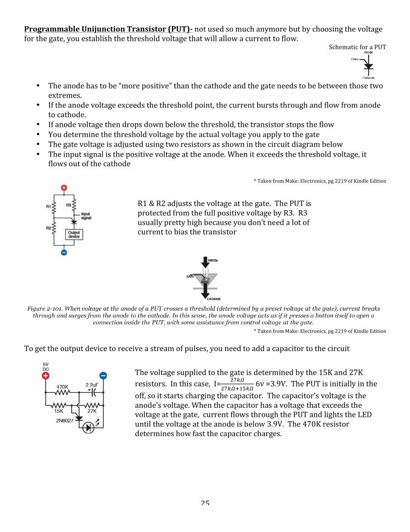
ProgrammableUnijunctionTransistor(PUT)-notusedsomuchanymorebutbychoosingthevoltageforthegate,youestablishthethresholdvoltagethatwillallowacurrenttoflow.
SchematicforaPUT
• Theanodehastobe“morepositive”thanthecathodeandthegateneedstobebetweenthosetwo
extremes.• Iftheanodevoltageexceedsthethresholdpoint,thecurrentburststhroughandflowfromanode
tocathode.• Ifanodevoltagethendropsdownbelowthethreshold,thetransistorstopstheflow• Youdeterminethethresholdvoltagebytheactualvoltageyouapplytothegate• Thegatevoltageisadjustedusingtworesistorsasshowninthecircuitdiagrambelow• Theinputsignalisthepositivevoltageattheanode.Whenitexceedsthethresholdvoltage,it
flowsoutofthecathode
*TakenfromMake:Electronics,pg2219ofKindleEdition
*TakenfromMake:Electronics,pg2219ofKindleEdition
Togettheoutputdevicetoreceiveastreamofpulses,youneedtoaddacapacitortothecircuit
R1&R2adjuststhevoltageatthegate.ThePUTisprotectedfromthefullpositivevoltagebyR3.R3usuallyprettyhighbecauseyoudon’tneedalotofcurrenttobiasthetransistor
Thevoltagesuppliedtothegateisdeterminedbythe15Kand27Kresistors.Inthiscase,I= !"!!
!"!!!!"!"6v=3.9V.ThePUTisinitiallyinthe
off,soitstartschargingthecapacitor.Thecapacitor’svoltageistheanode’svoltage.Whenthecapacitorhasavoltagethatexceedsthevoltageatthegate,currentflowsthroughthePUTandlightstheLEDuntilthevoltageattheanodeisbelow3.9V.The470Kresistordetermineshowfastthecapacitorcharges.
26
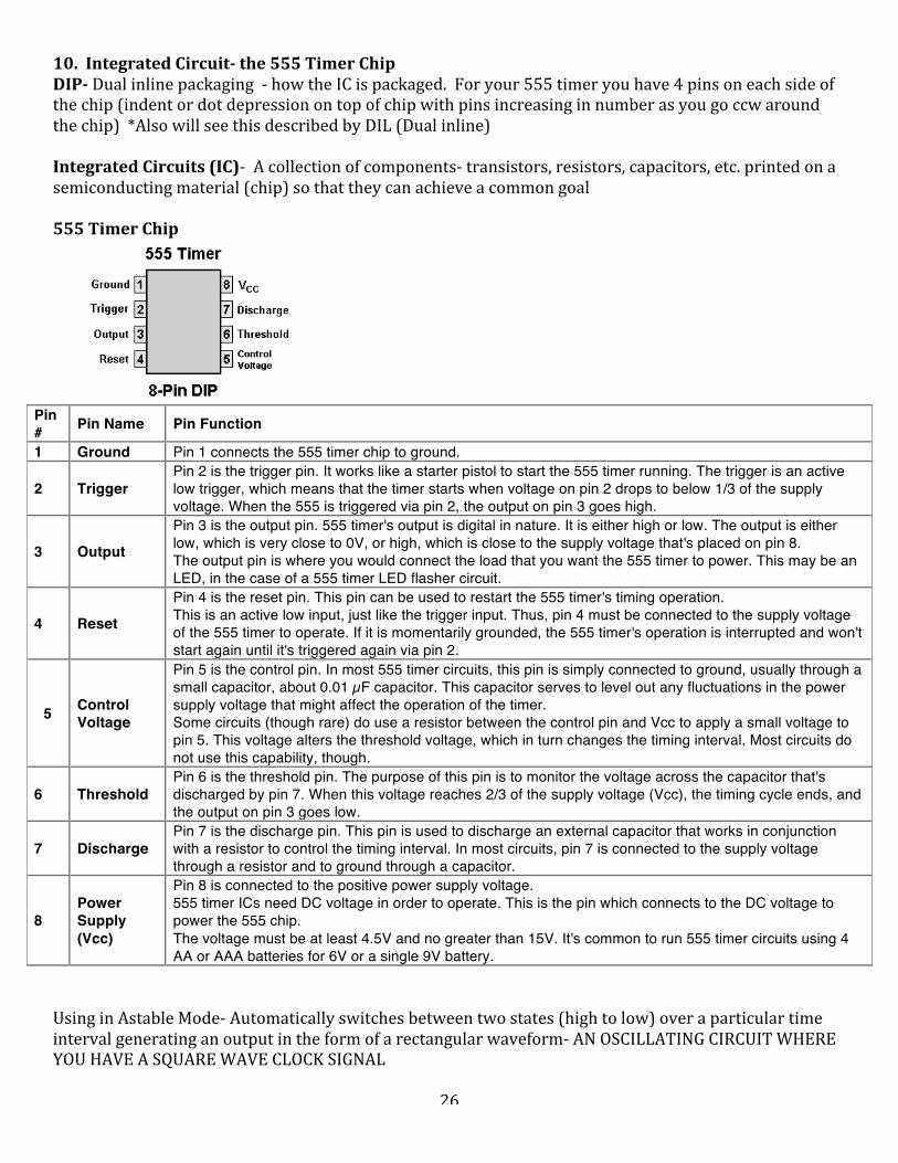
10.IntegratedCircuit-the555TimerChipDIP-Dualinlinepackaging-howtheICispackaged.Foryour555timeryouhave4pinsoneachsideofthechip(indentordotdepressionontopofchipwithpinsincreasinginnumberasyougoccwaroundthechip)*AlsowillseethisdescribedbyDIL(Dualinline)IntegratedCircuits(IC)-Acollectionofcomponents-transistors,resistors,capacitors,etc.printedonasemiconductingmaterial(chip)sothattheycanachieveacommongoal555TimerChip
Pin # Pin Name Pin Function
1 Ground Pin 1 connects the 555 timer chip to ground.
2 Trigger Pin 2 is the trigger pin. It works like a starter pistol to start the 555 timer running. The trigger is an active low trigger, which means that the timer starts when voltage on pin 2 drops to below 1/3 of the supply voltage. When the 555 is triggered via pin 2, the output on pin 3 goes high.
3 Output
Pin 3 is the output pin. 555 timer's output is digital in nature. It is either high or low. The output is either low, which is very close to 0V, or high, which is close to the supply voltage that's placed on pin 8. The output pin is where you would connect the load that you want the 555 timer to power. This may be an LED, in the case of a 555 timer LED flasher circuit.
4 Reset
Pin 4 is the reset pin. This pin can be used to restart the 555 timer's timing operation. This is an active low input, just like the trigger input. Thus, pin 4 must be connected to the supply voltage of the 555 timer to operate. If it is momentarily grounded, the 555 timer's operation is interrupted and won't start again until it's triggered again via pin 2.
5 Control Voltage
Pin 5 is the control pin. In most 555 timer circuits, this pin is simply connected to ground, usually through a small capacitor, about 0.01 µF capacitor. This capacitor serves to level out any fluctuations in the power supply voltage that might affect the operation of the timer. Some circuits (though rare) do use a resistor between the control pin and Vcc to apply a small voltage to pin 5. This voltage alters the threshold voltage, which in turn changes the timing interval. Most circuits do not use this capability, though.
6 Threshold Pin 6 is the threshold pin. The purpose of this pin is to monitor the voltage across the capacitor that's discharged by pin 7. When this voltage reaches 2/3 of the supply voltage (Vcc), the timing cycle ends, and the output on pin 3 goes low.
7 Discharge Pin 7 is the discharge pin. This pin is used to discharge an external capacitor that works in conjunction with a resistor to control the timing interval. In most circuits, pin 7 is connected to the supply voltage through a resistor and to ground through a capacitor.
8 Power Supply (Vcc)
Pin 8 is connected to the positive power supply voltage. 555 timer ICs need DC voltage in order to operate. This is the pin which connects to the DC voltage to power the 555 chip. The voltage must be at least 4.5V and no greater than 15V. It's common to run 555 timer circuits using 4 AA or AAA batteries for 6V or a single 9V battery.
UsinginAstableMode-Automaticallyswitchesbetweentwostates(hightolow)overaparticulartimeintervalgeneratinganoutputintheformofarectangularwaveform-ANOSCILLATINGCIRCUITWHEREYOUHAVEASQUAREWAVECLOCKSIGNAL

27
555TimerinAstableMode
ImportantConceptsandEquationsforastableuseof555asamultivibratorPeriod,τ-timeforonecompletecycle(unit-s)=tH+tL=timehigh+timelow
Frequency,f=!!is#ofcyclespersecond(units-1orHz)
f=!!= !.!!(!!!!!!)!
Timehigh(DEVICEON)=tH=0.693(RA+RB)CTimelow(DEVICEOFF)=tL=0.693RBCDutyCycleisthetimetheLED/Deviceishighascomparedtotheperiod
DutyCycle=!!!!!
(!!!!!!)= !!!!!!!
=!!!

28
11.IntegratedCircuit-CD4017-DECADECOUNTER/DIVIDER*Takenfromhttp://www.homemade-circuits.com/2011/12/how-to-understand-ic-4017-pin-outs.htmlon24thAugust2016
*Warning-thischipishighlysusceptibletodamagefromstaticelectricityTheCD4017isa16pinCMOSdecadecounter/divider.ThiscouldbeacoolwaytocontrolyourLEDssoyouhaveacascadingsequenceforyourLEDflashycircuit.Thenumber10isreferstothenumberofoutputsthisIChas,andtheseoutputsbecomehighinsequenceinresponsetoeveryhighclockpulseappliedatitsinputclockpinout.Itmeans,allits10outputswillgothroughonecycleofhighoutputsequencingfromstarttofinishinresponseto10clocksreceivedatitsinput.So,itiscountingandalsodividingtheinputclockby10andhencethename.
Let’sunderstandthepinoutsoftheIC4017indetailsandfromanewcomer’spointofview:Lookingatthefigureweseethatthedeviceisa16pinDILIC,thepinoutnumbersareindicatedinthediagramwiththeirassignmentnames.Thepinoutwhicharemarkedasoutputarethepinswhichbecomelogichighoneaftertheotherinsequence,meaningthefirstintheorderis3,sothispinistheonewhichfirstbecomeshigh,thenitshutsoffandsimultaneouslythenextpin#2becomes,thenthispingoeslowandsimultaneouslythepreceding

29
pin#4becomeshighandsoonuntilthelastpin#11becomeshighandrevertstopin#3torepeatthecycle.Pleasenotethattheword“high”meansapositivevoltagethatmaybeequaltothesupplyvoltageoftheIC,sowhenIsaytheoutputsbecomehighinasequentialmannermeanstheoutputsproduceapositivevoltagewhichshiftsinasequentialmannerfromoneoutputpintothenext,ina“running”DOTmanner.Nowtheabovesequencingorshiftingoftheoutputlogicfromzerotohighandbacktozero,happensonlywhenaclocksignalisappliedtotheclockinputoftheICwhichispin#14.Mindyou,ifthenoclockisappliedtothisinput,itmustbeassignedeithertoapositivesupplyoranegativesupply,butshouldneverbekepthangingorunconnected,asperthestandardrulesforallCMOSinputs.Theclockinputpin#14onlyrespondstopositiveclocksorapositivesignalandwitheachconsequentpositivepeaksignal,theoutputoftheICshiftsorbecomeshighinsequence,thesequencingoftheoutputsareintheorderofpinouts#3,2,4,7,10,1,5,6,9,11.Pin#13maybeconsideredastheoppositeofpin#14andthispinoutwillrespondtonegativepeaksignals,ifaclockisappliedtothispin,producingthesameresultswiththeoutputsasdiscussedabove.Howevernormallythispinoutisneverusedforapplyingtheclocksignals,insteadpin#14istakenasthestandardclockinput.However,pin#13needstobeassignedagroundpotential,thatmeans,mustbeconnectedtothegroundforenablingtheICtofunction.Incasepin#13isconnectedtopositive,thewholeICwillstallandtheoutputswillstopsequencingandstoprespondingtoanyclocksignalappliedatpin#14.Pin#15oftheICistheresetpininput.Thefunctionofthispinistorevertthesequencebacktotheinitialstateinresponsetoapositivepotentialorsupplyvoltage,meaningthesequencingcomesbacktopin#3andbeginsthecycleafresh,ifamomentarypositivesupplyisappliedtopin#15.Ifthepositivesupplyisheldconnectedtothispin#15,againstallstheoutputfromsequencingandtheoutputclampstopin#3makingthispin-outhighandfixed.ThereforetomaketheICfunction,pin#15shouldalwaysbeconnectedtoground.Ifthispinoutisintendedtobeusedasaresetinput,thenitmaybeclampedtogroundwithaseriesresistorof100Koranyotherhighvalue,sothatapositivesupplynowcanbefreelyintroducedtoit,whenevertheICisrequiredtobereset.Pin#8isthegroundpinandmustbeconnectedtothenegativeofthesupply,whilepin#16isthepositiveandshouldbeterminatedtothepositiveofthevoltagesupply.Pin#12isthecarryout,andisirrelevantunlessmanyICsareconnectedinseries,wewilldiscussitsomeotherday.Pin#12canbeleftopen.*Takenfromhttp://www.homemade-circuits.com/2011/12/how-to-understand-ic-4017-pin-outs.htmlon24thAugust2016