Practical Optimization of Steel Highway Bridge Beams ...
39
PRACTICAL OPTIMIZATION OF STEEL HIGHWAY BRIDGE BEAMS DECEMBER 1971 - NUMBER 23 R. H. BUSEK J. T. GAUNT A. D. M. LEWIS JOINT HIGHWAY RESEARCH PROJECT PURDUE UNIVERSITY AND INDIANA STATE HIGHWAY COMMISSION
Transcript of Practical Optimization of Steel Highway Bridge Beams ...

PRACTICAL OPTIMIZATION OF STEEL HIGHWAY
BRIDGE BEAMS
DECEMBER 1971 - NUMBER 23
R. H. BUSEK
J. T. GAUNT
A. D. M. LEWIS
JOINT HIGHWAY RESEARCH PROJECTPURDUE UNIVERSITY AND
INDIANA STATE HIGHWAY COMMISSION


Technical Paper
PRACTICAL OPTIMIZATION OF STEEL HIGHWAY BRIDGE BEAMS
TO: J. F. McLaughlin, DirectorJoint Highway Research Project
FROM: H. L. Michael, Associate DirectorJoint Highway Research Project
December 28, 1971
Project: C-36-56Q
File: 7-4-17
The attached Technical Paper "Practical Optimization ofSteel Highway Bridge Beams" has been authored by Messrs.R. H. Busek, J. T. Gaunt, and A. D. M. Lewis, members of thestaff of the School of Civil Engineering. Mr. Busek performedthe research resulting in this paper as a Graduate Assistantin Research on our staff.
The material in the paper is a summary of a researchreport presented to the Board at an earlier date. The paperis scheduled for presentation at the 1972 Annual Meeting ofthe Highway Research Board in Washington, D. C. in January.It is also planned for publication by that organization.
The paper is presented to the Board for approval ofpresentation and publication as noted.
Respectfully submitted,
Harold L. MichaelAssociate Director
HLM :ms
cc
:
w. L. Dolch R. H. Harrell W. T. Spencerw. H. Goetz M. L. Hayes J. A. Spoonerw. L. Crecco R. D. Miles N. w. SteinkampM. J. Gutzwiller J. W. Miller H. R. J. WalshG. K. Hallock C. F. Scholer K. B. WoodsM. E. Harr M. B. Scott E. J. Yoder
Technical Paper
PRACTICAL OPTIMIZATION OF STEEL HIGHWAY BRIDGE BEAMS
by
R. H. Busek
J. T. Gaunt
A. D. M. Lewis
Joint Highway Research Project
Project No. : C-36-56Q
File No. : 7-4-17
Purdue UniversityLafayette, IndianaDecember 28, 1971

PRACTICAL OPTIMIZATION OF STEEL HIGIIWAY BRIDGE BEAMS
R. H. Busek,
J . T . Gaunt
,
by
Structural EngineerN. H. Bettigole CompanyNew York, New York(Formerly Research Asoistajit,
Purdue University)
Assistant Professor of Civil EngineeringPurdue University, Lafayette, Indiana
A. D. M. Lewis, Associate Professor of Civil EngineeringPurdue University, Lafayette, Indiana
ABSTRACT
The cost optimization of a highway bridge girder, composed of a rolled sec-
tion acting compositely with the bridge deck, is formulated and programmed. An
objective function, based on the material and fabrication costs, is developed
and used in an exajnple. The design of the girder is controlled by the I969 AASHO
code.
Due to the complex loadings required on a highway bridge, the method of in-
fluence lines is used in the analysis. The analysis portion of the program pro-
duces the design conditions for the problem, which are used to design and optimize
the required girder.
Since the number of possible designs is fairly limited, the program uses the
exhaustive search technique. The techniques of intervaJ halving and dynamic pro-
gramming are also used within the design program. Interval halving is used to

Digitized by tlie Internet Arcliive
in 2011 witli funding from
LYRASIS members and Sloan Foundation; Indiana Department of Transportation
http://www.archive.org/details/practicaloptimizOObuse

Busek, Gaunt, Lewis 2
determine the thicknesses of the cover plates for the subelements, and dynamic
programming is used to determine the optimum location of the cover plate splices,
The computer program developed solves the simple-span problem as well as a
continuous girder of up to four spans. The girder can be either composite or
noncomposite and is designed for static and fatigue loads. All of the design
details are developed and then listed in the putput . No attempt is made to de-
sign the girder for deflection, but the total deflections for the final design
axe tabulated. The engineer has the option to optimize the design based on
either the total weight or the total cost.

Busek, Gaunt, Lewis 3
INTRODUCTION
Optimization is the process of obtaining "the best" solution to a prob-
lem based on a given criterion. Structureil optimization, therefore, is the
process of obtaining the "optimvim" solution to a structural problem. This
optimization is obtained by using anailysis and design theory and an optimum-
seeking method suited to the problem.
The formulation of the optimization problem depends on the type of struc-
ture being designed. For any problem, the design variables, the design con-
straints and the criterion of the optimization (the objective function) must
be defined. Values of the design parameters are desired so that the value of
the objective function is a minimum or maximum, as required, and the constraints
are not violated.
The design parameters required depend on the type of optimization problem
and on the theoretical equations used. The specification used to control the
design specifies the necessary constraints for the problem. In most problems,
both equality and inequality constraints are used.
The objective function can be euiy desirable measure of the effectiveness
of the design. Some of the measures which have been used are weight, cost,
cost-benefit ratios, and reliability. For the highway bridge girder, minimum
weight has been used for many years, because of the relationship which exists be-
tween weight and cost. For the problem studied in this paper, however, the cost
function used is more realistic because it includes the fabrication costs (3).
The methods used to solve optimization problems can be divided into direct
and indirect methods. The indirect methods are mathematical methods which can
use the gradient of the algebraic form of the objective function to solve a given
problem. Direct metnods are ones which make trial solutions in some organized
manner. The solutions are compared and a final optimum is chosen. Each of the

Busek, Ga\mt, Lewis ^
types has its own advantages and disadvantages when used in a particular struc-
tural optimization problem.
The optimization of girders has been extensively approached in the past by
using minimum weight as the measure of effectiveness (8, 9, 11, 12). The pro-
cedure has been to minimize the cross-sectional area of the girder. This in
turn minimizes the weight of the structure (U, 10).
The total cost optimization has been developed for both building and bridge
girders. The method of backtrack programming has been used to optimize the de-
sign of welded plate girders for buildings (l). The total cost optimization
work on highway bridge girders (5» 1^, 13) has led to the development of a com-
puter prograjn referred to as Girder Automated Design - I or GAD - I (6, T).
The program completely designs the constant depth plate girder and specifies all
of the design details, including the flange thicknesses, the flange splice loca-
tions ajid the locations of the transverse and longitudinal stiffeners if they
are required.
Since the GAD - I program has been developed, it has been possible to design
the optimum welded plate girder for a highway bridge. This girder, however, is
not necessarily the actual optimiim design for the problem. There is a possibility
that either a composite or noncomposite rolled-section girder may be more economical,
This is particularly true if the spans of the girder are relatively short.
In the present computer program development, the AASHO code (2) is used to
control the design of a highway bridge girder. The cross section of the girder is
limited to the 33- and 36-in. wide-flange rolled sections. The design can be either
composite or noncomposite and can have cover plates if they are required. The
girder is designed for all required static and fatigue highway loads. The fatigue
conditions are based on 500,000 cycles of stress. If the design is composite,
7/8-in. diameter shear connector studs are provided at the proper spacing.

Busek, Gaunt, Lewis 5
The method of exhaustive search is used in the program because of the limited
niimber of rolled sections of proper size. Each of the eighteen possibilities is
designed, using the method of interval halving to solve for the required cover
plate thicknesses. The method of dynamic programming is used to determine the
optimum location of the cover plate splices.
GIRDER ANALYSIS
The first problem that confronts the designer of a particular structure is
to determine the required design-load conditions. These conditions usually vary
with the size, purpose aund location of the structure. The actual conditions are
often designated by design specifications and can be found in design codes.
The necessary design loads for a highway bridge girder are specified by the
AASHO code. The code requires that the bridge structure must be designed for the
largest truck load and the corresponding equivalent lane load which the bridge
must sustain. The bridge may also be designed for an interstate loading condition
and for a sidewalk loading condition if pedestrian walkways are provided on the
bridge. These four types of loads constitute the live-load conditions for a high-
way bridge.
Besides the above live loads, the bridge must be designed for the required
dead-load conditions. Dead loads include the weight of the steel girder, the
weight of the deck slab, and the weight of the bridge railings and light fixtures.
If the design is noncomposite , then all of these loads are combined into one dead-
load condition. If the design is composite, the loads are separated into two
groups because they are resisted by different sections. The first group acts on
the steel girder only and. the second acts on the low modulus composite section.
The second group is referred to as the superimposed dead load or the long-term
live load.

Busek. , Gaunt , Lewi s 6
Once the loads which act on the structure have been defined, the stresses
caused by these loads must be determined. The design loads must be placed on
the structure so that maximum design conditions are developed at the critical
points in the structure. The determination of these design values constitutes
a complete analysis of the structure being designed.
Since the loading conditions, as shown above, for the highway bridge girder
are complex in nature, the method of influence lines is used to produce the de-
sign conditions. This method makes it possible to subject the structure to a
large niimber of loading conditions and to choose the controlling maximum from
these conditions.
The first step in the analysis is to determine the influence coefficients
for the reactions. These coefficients can be calculated by using equilibrium
and compatability equations. These equations can be set up in matrix form and
the resulting reaction influence coefficients can be determined by some method
common to matrix algebra. With these values, the moment and shear influence
coefficients at any point are easily determined by simple statics.
With the solution to all of the influence lines complete, emy line can be
chosen and loaded. Using the available influence line theories, all of the de-
sign conditions for the problem can be determined. The girder can then be de-
signed and optimized for these conditions.
ROLLED SECTION DESIGN
With the design conditions defined at each analysis point, the cross sec-
tion can be proportioned to carry the necessary design stresses. The design of
a particular rolled section can be determined in the following four steps:
1. Determine the required cover plates for the given section,
2. Design the cover plate welds for the section,

Busek, Gaunt, Lewis 7
3. Determine the shear connector spacing if the given
section is designed for composite action,
h. Design the bearing stiffeners if they are required
for the given section.
With these four steps, any rolled section can be designed to carry the stresses
determined in the analysis portion of the problem.
The determination of the cover plates for a particular rolled section re-
quires the following five steps:
1. Determine the plate width,
2. Determine the maximum moment for each subelement
,
3. Calculate the required plate thickness for each element,
h. Determine the cutoff location for each of the required
cover plate thicknesses,
5. Optimize the cover plate splice locations.
Since the required width of a cover plate is only dependent on the size of
the rolled section, the width of the flange is used to determine the plate width.
The range of flange widths for the 33- and 36-in. wide-flainge sections is approx-
imately 11.5 in. to l6.5 in. For ease of fabrication, the cover plate should be
narrower than the flange. If the cover plate width is specified in whole inches,
then Table 1 shows the plate widths used in the program for all the required sec-
tions. The smaller plate sizes proviae approximately 1 1/U in, to 2 l/U in. on
each side of tne plate. This makes it readily possible to weld the plate to the
flange of the rolled section.
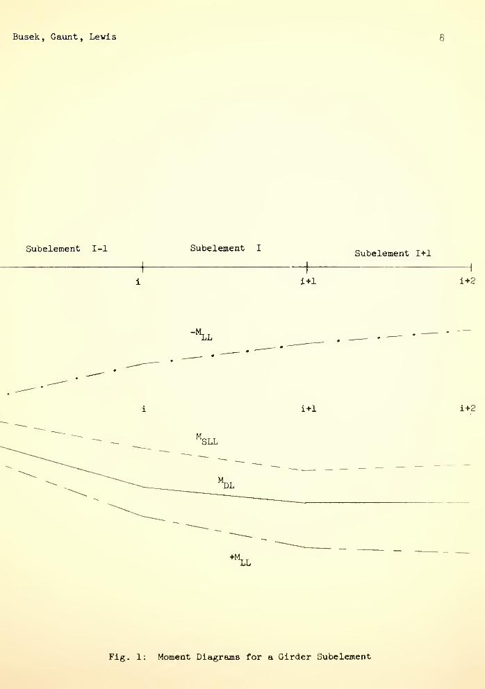
Before determining the thickness of the plate required for a given element,
the governing moment for the element must be determined. For an element I,
shown in Figure 1, tne governing moment is found at either point i or 1 + 1
.
If the dead-load moment at the end points are of the same sign, then the total
Busek, Gaunt, Levis
Subelement I-l Subelement ISubelement I+l
i+1 i+2
-'^I
i+l i+2
M.SLL
Fig. 1: Moment Diagrams for a Girder Subelement

Busek, Gaunt, Lewis
Table 1: Required Cover Plate Widths
Section Range of Min.) b(in.)
W33xll8 - W33xl52 11.U8U - 11.565 9
W36xl35 - W36xl9^ 11.9^*5 - 12.117 9
W33x200 - W33x2i+0 15.750 - 15.865 12
W36x230 - W3bx300 16.1+75 - 16.655 12
maximiim moments are detennined at each end. The plate thickness is then calcu-
lated for the location which contains the larger total moment. If there is a
change in the sign of the dead-load moment within the subelement , the thickness
is calculated for the set of moments at the negative dead-load moment location.
The cover plate cutoffs are subsequently determined in such a manner to insure
that the girder is not overstressed at any point.
After the governing moments are determined, the rolled section is tried
without cover plates. If aJLl the stress conditions are satisfied, then the
plate width and plate thickness for the subelement are set equal to zero and the
calculations for the subelement are complete. If the stress conditions are vio-
lated, then the required cover plate thickness must be determined.
The steel cross sections used in a rolled-section girder are shown in Figure
2. A symmetrical section is used in the negative moment region (Figure 2a).
The equation for the cover plate thickness can be derived by using the flexure
formula. The third-order equation for the thickness is
It^ + dt= .
f^"[^
Mtotbf
all
M. . dtot
?f -.ball
XX(1)
The equation for the cover plate thickness in the positive moment region is
extremely complex when compared to Kquation 1. This thickness equation is derived
from the following form of the flexure formula:
f
M vDL-'st
M yLVhmcall
StIhmc
M VSL^lmc
Imc
(2)

Busek, Gaunt, Levd.s 10
r 1 PL b X t
[,
Rolled Section(A +,I )sect XX
TZT"
^1
Trans formedConcrete Area (A /n)
c
slab
PL b X t
Rolled Section(A .,1 )
sect XX
1 PL b X t
2a: Negative MomentCross Section
2b: Positive MomentCross Section
Fig. 2: Steel Cross Sections

Busek , Gaunt , Lewis 11
All of the moments of inertia and the extreme fiber distances are functions of
the cover plate dimensions. The functional equation for the thickness, there-
fore, is
^ = ^ (^1)L''^LL'^SL''all'^'^xx'"'^'%'^ect''^'^)^'^^
Since both Equations 1 and 3 are complex in nature, a direct method of
solution is inappropriate. The method of interval halving is used to reduce
the number of calculations necessary for each thickness determination.
The technique of interval halving uses a bounded interval which is con-
tinuously reduced in size until a certain tolerance is obtained. In order to
reduce the interval by one-half with each calculation, the function must be
continuously increasing or decreasing. Figiire 3 shows that the relationship
between the cover plate thickness and the extreme fiber stress satisfies this
condition. By specifing the initial boundary conditions, the interval halving
process can be started and used to calculate the thickness which gives a bending
stress equal to f ^^. Any thickness which is larger than t ,-, is not economical^ all ^ ^ req'd
and any thickness less than t , ,produces stresses which violate the stress
req'd
constraints. The initial values of the bo\indaries, t and t . , are specifiedmsLX min
by the design constraints.
Steel plates are commercially available in thickness increments of l/l6 in.
The interval halving process, therefore, must produce thicknesses which are
multiples of 1/16 in. The initial interval must be specified such that the mid-
point of each subdivision is an exact multiple of .0625 in. The boundaries for
the initial interval must be separated by l/l6 in. times an integral power of 2.
The initial lower boundary (BL) and the initial upper boundary (UL) used
in the program are determined by Equation U:
If t. <^ l.UU in., BL = 5/16 in. and UL = 2 5/l6 in.^
(MIf t > l.UU in., BL = T/l6 in. and UL = 2 T/l6 in.

Busek, Gaunt, Lewis 12
t > t
C = Cost of the cover plate
C(t) > C(t ,,)req'd
mln
all
Fig. 3: Plate Thickness vs Base Stress

Busek, Gaunt, Lewis 13
All of the thicknesses determined from these initial starting boundaries, satisfy
the width-to-thickness ratios for cover plates which are specified by AASHO.
With the initial interval specified, the plate thickness is set equal to
the interval midpoint. If the M^ is positive, then Just a bottom plate is
required. If NL is negative, then plates are used on the top and bottom of the
rolled section. The properties of the defined steel section are determined and
the bending stresses are calculated.
The allowable static and fatigue stresses are then determined and compared
to the actual bending stresses. If the allowable stresses are not violated,
then the upper bound of the interval is set equal to the interval midpoint.
This completely eliminates the upper half of the interval as being not as eco-
nomical as the midpoint. If the allowable stresses are violated, then the mid-
point becomes the lower bound. This eliminates the lower half of the interval
because the thicknesses do not satisfy the stress conditions. The process is
continued, using the new interval, until a final interval of less than I/I6 in.
is obtained. The t , , is then equal to the boundary value which satisfies allreq'd
of the stress conditions.
The method of interval halving greatly reduces the required number of cal-
culations required to solve the thickness equations. The thickness of any sub-
element can be determined by considering only five different plate thicknesses.
For example, if the required plate thickness for a W36xl60 section is 1 in.,
the plate thicknesses which must be tried are 1 5/l6, 13/I6, 1 I/16, I5/I6, and
1 in. The interval sizes and boundaries used in this determination are shown
in Table 2. If elII the thicknesses between 5/l6 and 1 in. were calculated,
twelve series of calculations would be necessary. The interval halving technique
reduces this number to five, thus reducing tne necessary computation costs.
This saving would be even greater if the cover plate thickness were greater than

Busek, Gaunt, Lewis lU
1 in.
Table 2: Interval Data for the Sample Example
Series UL BL Midpoint
1 2 5/16 5/16 1 5/16
2 1 5/16 5/16 13/16
3 1 5/16 13/16 1 1/16
h 1 1/16 13/16 15/16
5 1 1/16 15/16 1
Using interval halving, the required plate thickness for each subeleraent can be
determined. Once this is complete, tne cutoff location for each plate end must
be calculated. These cutoffs are based on static and fatigue stress requirements,
The fatigue formula specified in the 1969 AASHO code is
k^ f
r 1 - k^ R
(5)
vhere k^ = 1.0 + a ( ^g^^ - 1 )
The fatigue constants, k„, f , and a, are based on the location, the typec ro
of stress under consideration and the number of stress cycles. All of the fatigue
constants used in the computer program are based on 500,000 cycles of stress.
If the location of the stress is the end of a cover plate, the allowable fatigue
stress is
12000'r= 1 - H
The fatigue equations for two cover plates butt welded together are
17200 k.
(6)
F = ^-=-r 1 - .b2R
F =r
,55F
jjt
for tension
for compression
:t)
1 - ( 10600 k^ -1 ) R

Busek, Gaunt, Lewis 15
For a given point on the girder, the stresses are calculated and compared
to the allowable stresses found using Equation 6 or 7- For simplicity, the
static stress is also checked at the actual cutoff rather than at the theoreticaJ.
cutoff location as specified in the AASHO code. The reason for this is to save
the calculation cost required for the added moment interpolation. If the actual
stresses are less than the allowables, the plate can be cut off into a higher
moment region, thus saving in plate cost. The cover plate must be extended into
a lower moment region if the stress conditions are violated. This results in
an added cost which is necessary to insure that the design constraints are not
violated.
The cutoff distance for a particular plate is determined by using an increasing
step size technique. The initial step size is set equal to 1 in. if the plate is
to be cut or extended to the right. A negative value is used if the cutoff or
extension is to the left. This step is referred to as DIST in the program.
For a particular step size, the moments are determined by straight line
interpolation and the maxiraura stresses are determined. The maximum is compared
to the allowable and the step size is doubled. The process is continued until a
location which has the stress Just equal to the allowable is determined. If, at
any time during the cutoff operation, the actual location is passed, the last
acceptable location is retained and the step size is initialized at 1 in. The
process is then continued from the last acceptable location. This enables tne
cutoff point to be located to the nearest inch.
Throughout the cutoff operation, provision is made for many unique occurrences.
Some of these provisions are:
1. Extension of a cover plate througn a section of
zero thickness,
2. A mELximum cutoff distance is set and not exceeded.

Busek, Gaunt, Levis l6
3. The minimum length cover plate is supplied over
the interior supports,
h. Complete elimination of a thinner plate by a
thicker plate.
All of the above situations must be and are considered in the design.
With the completion of the cutoff for each cover plate thickness, the total
cover plate system for a particular rolled section is defined. The size of each
required cover plate between certain coordinates is now specified. The total
cost of the system must now be minimized and the optimum location of the splice
points must be determined. This optimization is achieved by using dynamic pro-
gramming.
Dynamic programming is a method used to optimize sequential problems. It
can be applied to situations in which many decisions must be made, as long as
the decisions made at later stages do not affect the performance of the earlier
stages. The method decomposes the problem into a set number of individual pro-
blems. In determining the optimum condition for a section, the only quantities
involved are the variables in the next adjacent section and the value of the ob-
jective function for the system up to and including the preceding section.
The use of dynamic programming in optimizing steel girder flanges was
developed by Goble and DeSantis (5, 6, 7) and Razanni (13, I'O • The method was
used to determine the optimum location of the flange splices in the GAD-I pro-
gram. The use of the method, to determine the splice locations for cover plates,
is an extension of the method used for the welded plate girders.
In using the technique to determine the splice locations for each cover plate
on a rolled section, the variable which is desired for each section is the plate
thickness and the objective function is the toteil cost of the cover plate system.
The sequence of sections is defined by the required thicknesses which have been

Busek, Gaunt, Lewis 17
previously determined. Each section has a required thickness, a required plate
width, a starting coordinate and a final coordinate. The governing cost equation
for a particular section is
C, = C + C + C (8)i m sw ew ^ '
where C is the cost of the material, C is the seal weld cost and C is them sw ew
end weld cost
.
The cost of any weld can be determined from Equation 9:
^weld = ^1 ^ ^2 (^^ ^ S ^^^ (9)
In Equation 9, C is the fixed cost of the given weld, C (V) is a variable cost
based on the volume of the weld material and C^ (L) is a variable cost based on
the length of the weld. The equation for the cost of a fillet weld is
^fillet = ^1 " 1/2 t/ L^ c^ - L^ C3 (10)
and the equation for the cost of a butt weld is
Cw ^v = ^1 + (-12^ t + .289 t 2) L c_ + L c^ (11)
butt 1 w w w 2 w 3
The fillet weld cost is based on a weld cross section of an equilateral triangle
with sides of t . The butt weld cost is based on the cross section of a standardw
double-vee butt weld having a thickness of t .
w
The initial step in the dyanmic programming sequence is to set up a working
array. This array is the PTH array and contains all of the information regarding
the required cover plates. The information for a cover plate section I is
1. PTH (1,1) = t ,,req'd,
2. PTH (1,2) = the width of the required plate,
3. PTH (1,3) = the starting coordinate of the section,
h. PTH (I,U) = the final coordinate of the section.
In order to simplify the equations presented below, the following substitutions
will be used:

Busek, Gaunt, Lewis l8
1. T (I) = PTH (1,1)
2. B (I) = PTH (1,2)
3. L (I) = PTH (I,U) - PTH (1,3)
U. TMIN = the lesser value of T (I) and T (l-l)
There are actually four different conditions which must be treated in the
optimization of the cover plates. These conditions lead to four equations which
can be used to determine the total cost of the system up to and including section
I. The four conditions and equations are:
1. Condition I - T (I) = 0.0 and T (l + l) > 0.0
^1 ^^left-^^'^l^^ (^^1) (-3"^/'^2C ) (^2)
where C is the cost of the cover plate system to the left of section I for
the value of T (l) used.
2. Condition II - T (I) > 0.0 and T (l + 1) = 0.0
^I = ^left ^ ^(^) ^(^) «(^) =m I^ ^ ^1 ^ ^(^) (^3 ' ^1^ ^2 \ ^
+ 2 L(I) (c^ + .00673 c^) (13)
3. Condition III - T(l) i T(l + l)
C^ => C. _ + L(I) T(I) B(I) c T-^ + c + 2 L(I) (c. + .00673 c^)I left m 172d 1 3 2
+ B(I) c, + (.125 TMIN + .289 TMIN^) B(l) c„ (1^4)
U. Condition IV - T( I ) = T(l - 1
)
Cj = C^^^^ + L(I) T(I) B(I) c^ 3^ + 2 L(I) (c^ + .00673 c^) (15)
The following assumptions are used in developing Equations 12 to 15:
1. The end welds are of the minimum thickness required for
the plate being used,
2. The end welds are across the end of the plate only.

Busek, Gaunt, Lewis 19
3. The minimum size seal weld (5/l6 in.) is used in all cases.
The dynamic programming process, for a section I, consists of using either
Equation 12, 13, 1^ and 15 to calciilate the total cost of the plate system.
Using a set thickness in section I + 1, the plate thickness in section I is
varied and all the costs are calculated. The thickness of a section is varied
from t,J to the maximum thickness required on the rolled section. All of the
req'd
different thicknesses required on rolled section are calculated. For a given
thickness in section I + 1, T(l + l), the optimum thickness in section I can be
chosen directly. This optimum thickness can then be placed in a storage array
for future use
.
The thickness storage array, TP, is a two-dimensional array having one row
for each cover plate section sind one column for each plate thickness. The TP(I,J)
element contains the optimum thickness for section I when the thickness in section
I + 1 equals STTH(j). The STTH array contains all of the required plate thicknesses
arranged in ascending order.
The cost of the final section is calculated for all of the available thicknesses
ajid the optimum thickness is determined directly. With tnis thickness, all of the
other thicknesses are determined from the TP array by working from right to left
along the girder. With these thicknesses determined, the information in the PTli
array is converted into the actual cover plate information and is stored in the
proper location in the COVPL array.
To further explain the method of dynamic programming and its use in optimizing
the cover plates of a rolled section, a sample problem is presented. Shown in
Figure hsi is a required cover plate arrangement. Using c = $.15/pound, c $30.00/
pound and no volume or length cost for a weld, the dynamic programming process
is approached as follows:
1. Get up the STTH array.
STI'H = (0.0, 0.5, 1.0)

Busek, Gaunt, Lewis 20
100"
1 "
2
100"ia 1-^
100"
1"
100"
Plate Width = 10"
Ua: Required Cover Plate Arrangements
200" 200'
Total Cost = $277.80
Ub Optimum Cover Plate Arrangement
1"
2
Fig. h: Cover Plate Optimization Example

Busek, Gaunt, Lewis 21
2. Calculate the cost of section 1 for all the possible
thickness combinations.
T(I) T(2) Equation^left
C ^sect ^1
.5 0.0 13* 0.0 $lUl.30 $lUl.30
1.0 0.0 13* 0.0 $162.60 $162.60
.5 .5 15* 0.0 $111 . 30 $111.30
1.0 .5 Ik* 0.0 $162.60 $162.60
.5 1.0 Ik* 0.0 $lUl.30 $lUl.30
1.0 1.0 15* 0.0 $132.60 $132.60
* The equation has been altered slightly to include the initial fixed
cost of the seail welds and the initial end weld cost.
3. Place the appropriate values in the TP array.
0.0 0.5 1.0
TP = 1 .5 .5 1.0
h. Calculate the costs for section 2 for all of the
thickness combinations.
t(2) Tl'j) Equation cleft
Csect ^'l
0.0 1.0 12 $li4l.30 $90.00 $231.30
.5 1.0 lU $111.30 $51.30 $162.60
1.0 1.0 15 $132.60 $i*2.60 $175.20
Place the appropriate values in the TP array,
0.0 0.5 1.0
TP =
1.0
.5

Busek, Gaunt, Lewis 22
Calculate the costs for section 3 for all of the
thickness combinations.
T(3) T(M Equation^left
Csect ^1
1.0
1.0
.5
1.0
lU
15
$162.60
$162.60
$72.60
$i42.60
$235.20
$205.20
T. Place the appropriate values in the TP array.
0.0 0.5 1.0
TP = 2
3 1.0
1.0
.5
1.0
8. Determine the optimum thickness in section U.
"tHT Equation'left sect 'total
.5
1.0
13
13
$235.20 $51.20 $286,140
$205.20 $72.60 $277.80
The optimum T{U) is 1.0 in.
9. Using the TP array (Step 7), choose the thickness
for each section.
T(lj) 1.0 in.
T(3) 1.0 in.
T(2) 0.5 in.
T(l) 0.5 in.
10. The optimum cover plate arrangement is shown in Figure lib.
With the completion of the dynamic programming process, the cover plates are
defined for the rolled section under consideration. The design details must be
calculated. These details include the design of the cover plate welds, the de-
sign of the bearing stiffeners and the calculation of the shear connector spacing
if the design is composite. In the optimization problem, each of these details

Busek , Gaunt, Lewis 23
must be completed for each design because they add a substantial cost to the
girder.
The velds which must be determined for each cover plate include the end
welds and the seal welds. Each of these welds is designed as a fillet weld and
is expressed in values which are multiplies of a sixteenth of an inch. The end
welds are designed to carry the flexural stress developed at a distance of 1.5
times the plate width from the end of the plate. The seal welds are designed
to carry the maximum shear stress developed along the length of the plate. A
minimum size fillet weld is specified by the code depending on the thicknesses
of plates being joined.
The bearing stiffeners are required to transfer the large web shear at tne
reactions to prevent web crippling. In most of the wide-flajige rolled sections
bearing stiffeners are not required. The AASHO code requires stiffeners in those
girders which have shear stresses in excess of 75 percent of the allowable shear
stress. If bearing stiffeners are required, they are designed as columns having
a section composed of the stiffener plates and a portion of the web which is l8
times the web thickness in length.
The shear connectors for a composite girder are designed to transfer the
horizontal shear from the slab to the steel girder. These connectors are placed
transversely across the flange at either regular or variable spacings. The con-
nectors are designed for fatigue and checked for ultimate strength.
With the completion of the design detail calculations, the design of a rolled
section is complete. The total cost of the girder con then be calculated. This
cost is used in the comparison of all the designs and the optimum can be chosen.
COMPUTET! PROGRAM
The computer program for the design of rolled-section girders consists of
two parts. The ejialysis portion is used to determine the design conditions for

Busek, Gaunt, Lewis 2U
the problem and the design portion is used to determine the optimum combination
of rolled section and cover plates. The entire program is composed of a MAIN
program and thirty- four subroutines. The purpose of the t-lAIN program is to call
on the subroutines in the correct sequence to produce the optimum design for the
particular girder.
The first step in solving any problem is to specify the data. There are
actually two sets of data required for a problem. The rolled section properties
are read directly from cards by the MAIN program. The problem data are then
read from cards by the READIN subroutine. A detailed description of the data
input is presented in the program description (3).
After the complete problem is defined, the initial analysis must be completeu.
The ANAL subroutine is used to determine an initial set of design reactions, de-
sign moments, and design shears. These conditions are then used in the first de-
sign cycle.
The design cycle is started by determining the lighest uniform section which
will carry the design loads. This is accomplished by designing each section,
starting with the heaviest, and proceding in descending weight order, without
cover plates at the critical moment location until the lighest acceptable section
is determined. By assuming that the cost of the shear connectors and stiffeners
for a uniform section is independent of the section used, all of the sections
heavier then the one which has been determined can be eliminated from the search.
This means that a number of rolled sections need not be designed completely and
a resulting savings in computation costs is realized.
The rolled section which is being used as a uniform section is completely
designed. The objective function is then used to determine the weight and/or
cost of the design depending on the basis of tne optimization. This uniform de-
sign then becomes the initial design for the problem.

Busek, Gaunt, Lewis 25
Each of the remaining lighter sections is designed using the steps described
above. After each design is complete, the weight and/or cost is determined. The
required measure of effectiveness is compared to the value for the present optimum
design. If the design is "better", it replaces the present optimum in the storage
arrays. If the design is not as economical, the present optimum is retained.
After all of the sections are designed, the cycle is complete.
Using the optimum design from the previous cycle, the girder is reanalyzed
and a new set of design conditions is calculated. There are three options which
can now be executed by the program. The optimum girder can be redesigned for the
new conditions and this final design can be accepted as the optimum. It is also
possible to specify the number of design cycles desired. If this option is used,
the design cycle is repeated the required number of times and the final solution
obtained is the optimum design.
The third, and most useful, option is a converging-moment option. The value
of the critical moment is compared to the value obtained from the previous analysis.
If the change in the moment is less than a percentage specified in the input, the
program is terminated and the present optimum is used as the final solution. If
the percent change is greater than that specified, a new design cycle is started.
This procedure is continued until the moments converge or until a specified maximum
number of cycles is reached.
Once the final design is obtained, the required deflections are calculated
based on the final distribution of the moments of inertia. All of tne information
pertaining to the optimum design is made available in the output. This Includes
the section properties, the required cover plates, the required stiffeners, the
shear connector spacing and the deflections. The cost or weight of the final de-
sign is also presented.

Busek, Gaunt, Lewis 26
SAMPLE PROBLEM
In order to show the usefulness of the computer program, a sajaple girder
has been designed. The problem is originally presented in the United States
Steel Highway Structures Design Handbook (15). The costs of the manual design
and the computer program design are compared below.
The problem is a two-span girder having equal span lengths of TO ft. The
design is based on a composite section having the properties listed in Table 3.
The design loading is the AASHO HS20 loading.
Table 3: Composite Section Properties
Property Value
Slab Width 8U.00 in.
Slab Thickness 7.00 in.
fc
3000.00 psi
iModular Ratio 8.00
Area of Steel ^4.3'* sq in.
Haunch 1.875 in.
The optimization of the girder is based on total cost and the unit coats used in
the optimization procedure are listed in Table U.
Table U: Unit Costs
Item Unit Cost in dollars
Rolled Section lb 0.15
Cover Plates lb 0.12
Stiffeners lb 0.12
Connectors lb 0.00
Connector Installation ea 0.75
Fixed Weld Cost ea 20.00
Weld Material Cost cu in . 2.00
Weld Lenpth Cost in
.
0.00

Busek, Gaunt, Lewis 27
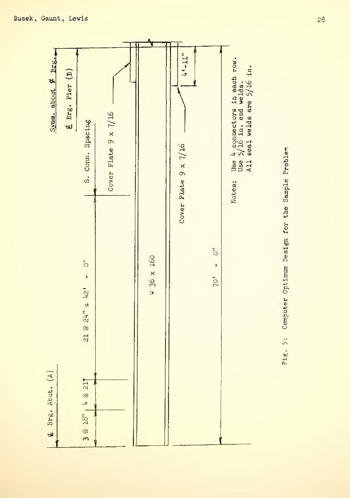
The final design produced by the computer progrsLin is shown in Figure 5.
The itemized costs eind weights of both the computer solution and the manual
solution are given in Table 5.
Table 5: Itemized Costs and Weights for the Two-Span Sample Problem
U.S. Steel Manual Computer Program
Item Weight Cost Weight Cost
Rolled Section 18900.0 $2835.00 22UOO.O $3360.00
Cover Plates 2361.6 $ 283.^0 360.1 $ 31.22
Stiffeners
Connectors 202.2 $ 193.50 179.8 $ nh.oo
Welds $ 628.29 $ 207.26
Totals 21U63.8 $39^0.19 22839.9 $3772. U8
Table 5 shows that the optimization program produced a girder which is ap-
proximately 6.U percent heavier than the girder found in the manual. The optimum
design, however, costs ^,3 percent less than the manual design. Most of the cost
reduction can be found in the cover plate cost. The total cost of the plates,
including both material and fabrication costs, for the optimum girder is $238. U8.
The same costs for the manual design give a total of $911.69 or approximately
four times as much as the program solution. This cost difference offsets the in-
creased cost of the rolled section used in the optimum design.
The computer program used to solve this problem is approximately I^OOO cards
in length and was developed and executed on the CDC 65OO computer. The compilation
time for tne program is about U8 seconds and the execution time for the above sample
problems was about hO seconds.
Busek, Gaunt, Lewis 28
upq
o
CO
«
^1
V
(X
PP
•HO
CO
oo
CO
o
I
CM-4-
CM
®CM
<"
^• CM
+J3 ®^>< -:!
•
60 -
U CO« rH
S»
^
M3
CJ\
0)
-P
U<u?•
oCJ
o
VO
\
i-H
(1>
IpL,
0)?•
oo
o
o
§u
o •
OS CO^
I-H ITNa oj•H ?
O 0)po •
0} a
aovo
-a- ur\
2J
03
CO
0) (U -Hto to r-H3D <
a<uPos
VH
to•H

Busek, Gaunt, Lewis 29
CONCLUSIONS
This computer program is another step in the automation of steel beam bridge
design. The previous sample problem shows that cost savings are possible using
the total cost concept in design. The digital computer raaJ^es possible the use
of optimum-seeking methods in practical problems such as highway design. How-
ever, a large number of problems remain to be solved before the optimization of
an entire bridge design project will be possible.
ACKNOWLEDGMENTS
The authors wish to acknowledge the financial support of the Joint Highway-
Research Project. The guidance and help of Professor Harold L, Michael, the
Associate Director of the Project, is appreciated. The aid and support of the
Indiana State Highway Commission is also appreciated.
NOMENCLATURE
A - area of concrete slabc
A ^ - area of the steel sectionsect
b - cover plate width
c , c , c - unit cost parameters
d - depth of the rolled section
f ,
,
- allowable stressall
F - fatigue Eillowable stressr
F - steel tensile strengthu
f - width of the steel section flange
F - steel yield point stressy
h - depth of the haunch
I, - moment of inertia of the high modulus sectionhmc
I, - moment of inertia of the low modulus sectionImc

Busek, Gaxint, Lewis 30
St
XX
w
•'Sl
M.LL
M
n
R
t
t.
SL
hmc
Lmc
St
moment of inertia of the steel section
moment of inertia of the rolled section
length of a weld
dead load moment
live load moment
superimposed live load moment
modular ratio
ratio of the minimum stress to the maximum stress
cover plate thickness
thickness of the flange
thickness of concrete slab
veld size or thickness
extreme fiber distance for the high modulus section
extreme fiber distance for the low modulus section
extreme fiber distance for the steel section

Busek, Gaunt, Lewis 31
REFERENCES
1. Annamalai, N.: Cost Optimization of Welded Plate Girders ,
Ph.D. Thesis, Purdue University, 1970.
2. American Association of State Highway Officials, Standard
Specifications for Highway Bridges , Tenth Edition, I969.
3. Busek, R. H.: Practical Optimization of Steel Highway Bridge
Beams , M.S.C.E. Thesis, Purdue University, 1971.
h, Edward, C. K. axid L. H. Gary: "Minimum Weight Proportions
for Steel Girders", ASCE Journal of the Structural Division,
Vol. 95, No. 10, Oct. 1969.
5. Goble, G. and P. V. DeSantis: "Optimum Design of Mixed Steel
Composite Girders", ASCE Journal of the Structural Division,
Vol. 92, No. 12, Dec. I966.
6. Goble, G. and P. V. DeSajitis: Girder Automated Design - I ,
Vol. 1 - User's Manual, Oct. I968.
7. Goble, G. and P. V. DeSantis: Girder Automated Design - I ,
Vol. 2 - Maintenance Manusil , Oct. I968.
8. Hahn, E. W. : Minimum Weight Elastic and Plastic Design of
Beams and Simple Structures , Ph.D. Thesis, June 19t>i, Purdue
University.
9
.
Haug , E . : Minimum Weight Design of Beams with Inequality
Constraints of Stress and Deflection , Ph.D. Thesis, I966
,
Kansas State University.
10. Holt, E. C. and C. L. Heithecker: "Minimum Weight Properties
for Steel Girders", ASCE Journal of the Structural Diviaion .
Vol. 95, No. 10, Oct. 1969.

Busek, Gaunt, Lewis 32
11. Kristiman, S. and K. V. Shetty: "On the Optimum Design of an
I-Section Beam", Journal of Aerospace Science , No. 26, 1959.
12. FCrishman, S. and K. V. Shetty: "A Method of Minimum Weight
Design for Thin-Walled Beams", Structural Engineer, No. 5, 196l
.
13. Razani , R.: The Iterative Smoothing Method and Its Application
to Minimum Cost Design of Highway Bridge Girders , Ph.D. Thesis,
1965, Case Institute of Technology.
lU. Razani, R. and G. Goble: "Optimum Design of Constant Depth Flate
Girders", ASCE Journal of the Structural Division , Vol. 92, Apr.
1966.
15. United States Steel Company: Highway Structures Design Handbook ,
Volumes 1 and 2, I965.