Practical Numerical Simulation of Laser Welding for ... · Introduction • Laser Welding of Metals...
16
Copyright © 2014 Owens Corning. All Rights Reserved. Practical Numerical Simulation of Laser Welding for Industrial Use B.L. Bemis
-
Upload
duongthien -
Category
Documents
-
view
224 -
download
4
Transcript of Practical Numerical Simulation of Laser Welding for ... · Introduction • Laser Welding of Metals...
Copyright © 2014 Owens Corning. All Rights Reserved.
Practical Numerical Simulation of Laser Welding for Industrial Use B.L. Bemis
Introduction
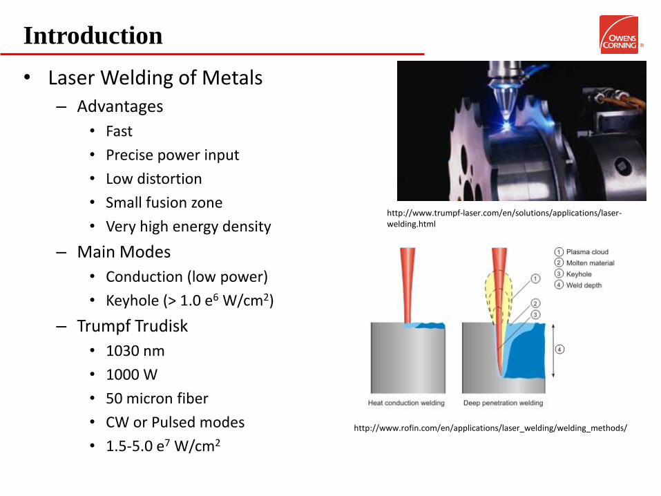
• Laser Welding of Metals – Advantages
• Fast
• Precise power input
• Low distortion
• Small fusion zone
• Very high energy density
– Main Modes
• Conduction (low power)
• Keyhole (> 1.0 e6 W/cm2)
– Trumpf Trudisk
• 1030 nm
• 1000 W
• 50 micron fiber
• CW or Pulsed modes
• 1.5-5.0 e7 W/cm2
http://www.rofin.com/en/applications/laser_welding/welding_methods/
http://www.trumpf-laser.com/en/solutions/applications/laser-welding.html
Problem Considerations & Motivation
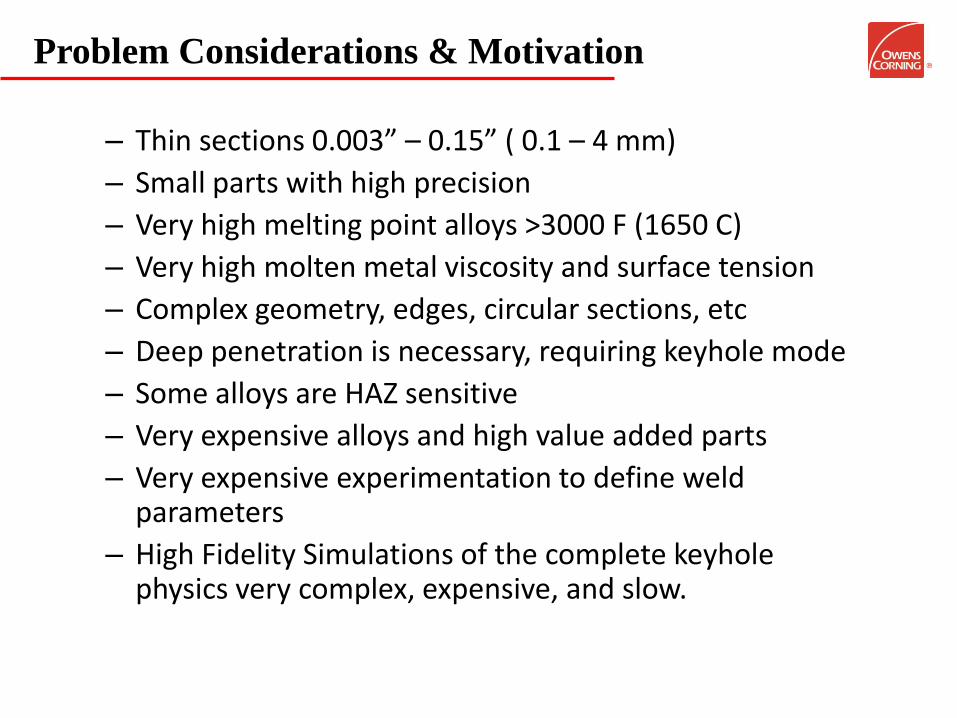
– Thin sections 0.003” – 0.15” ( 0.1 – 4 mm)
– Small parts with high precision
– Very high melting point alloys >3000 F (1650 C)
– Very high molten metal viscosity and surface tension
– Complex geometry, edges, circular sections, etc
– Deep penetration is necessary, requiring keyhole mode
– Some alloys are HAZ sensitive
– Very expensive alloys and high value added parts
– Very expensive experimentation to define weld parameters
– High Fidelity Simulations of the complete keyhole physics very complex, expensive, and slow.
Problem Considerations
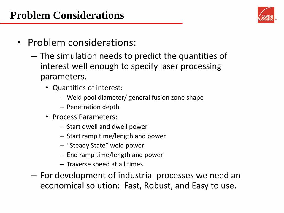
• Problem considerations: – The simulation needs to predict the quantities of
interest well enough to specify laser processing parameters. • Quantities of interest:
– Weld pool diameter/ general fusion zone shape
– Penetration depth
• Process Parameters: – Start dwell and dwell power
– Start ramp time/length and power
– “Steady State” weld power
– End ramp time/length and power
– Traverse speed at all times
– For development of industrial processes we need an economical solution: Fast, Robust, and Easy to use.
Problem Considerations
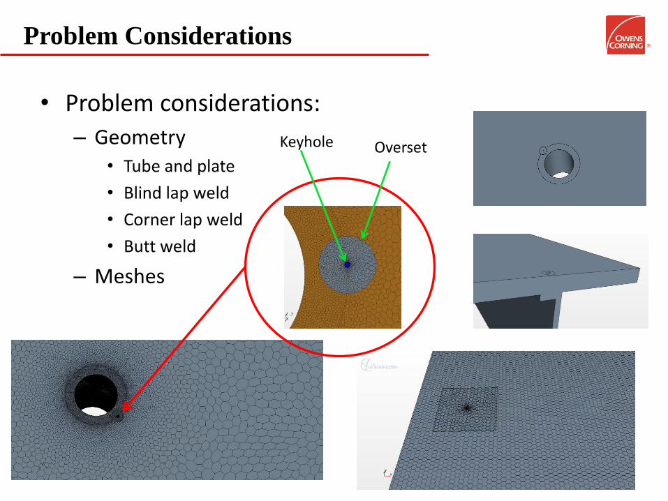
• Problem considerations:
– Geometry • Tube and plate
• Blind lap weld
• Corner lap weld
• Butt weld
– Meshes
Keyhole Overset
Problem Considerations
• Problem set-up: – Weld sections modeled as a single volume – Solid conduction only, high viscosity and high surface tension – Weld pool characterized as an iso-surface at melt
temperature – Keyhole as a volumetric source
• Diameter, shape, power distribution, and depth determined a-priori from literature references and experimental results.
• Commonly simulated as a cylinder of 2x the radius of the beam at the focal point
– Overset mesh used for the moving heat source – Mesh refinement in the weld zone path – Implicit unsteady solver – Weld speed, laser power, time step controlled by field
functions.
Problem considerations: Keyhole Physics
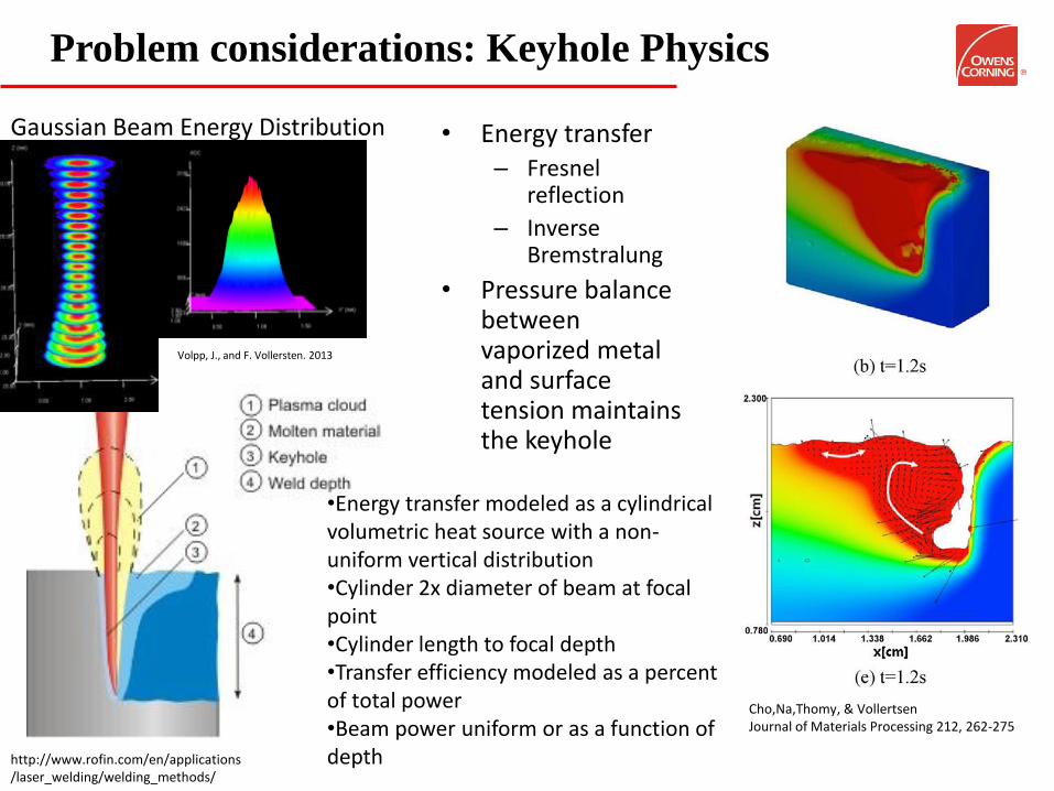
Cho,Na,Thomy, & Vollertsen Journal of Materials Processing 212, 262-275
• Energy transfer – Fresnel
reflection
– Inverse Bremstralung
• Pressure balance between vaporized metal and surface tension maintains the keyhole
•Energy transfer modeled as a cylindrical volumetric heat source with a non-uniform vertical distribution •Cylinder 2x diameter of beam at focal point •Cylinder length to focal depth •Transfer efficiency modeled as a percent of total power •Beam power uniform or as a function of depth http://www.rofin.com/en/applications
/laser_welding/welding_methods/
Volpp, J., and F. Vollersten. 2013
Gaussian Beam Energy Distribution
Problem Considerations
• Solution – Variable time step.
• Small during initial heat-up and start ramp.
• Larger during steady state movement
• Smaller at turns and at the end ramp
• Time step controlled to be less than ½ a cell size per move
– Energy controlled inner iterations • Stop inner iterations with Energy monitor set at 1e-8
– Under relaxation factor for energy set at 1
– Ensure that the maximum temperature is set high enough to prevent clipping. T > 20000 K are expected.
• Good practice to do a time step study – Halve the time step and check solution several time to
ensure the solution is temporally resolved
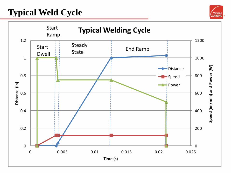
Typical Weld Cycle
0
200
400
600
800
1000
1200
0
0.2
0.4
0.6
0.8
1
1.2
0 0.005 0.01 0.015 0.02 0.025
Spe
ed
(im
/min
) an
d P
ow
er
(W)
Dis
tan
ce (
in)
Time (s)
Typical Welding Cycle
Distance
Speed
Power
Start Dwell
Start Ramp
End Ramp Steady State
Solutions
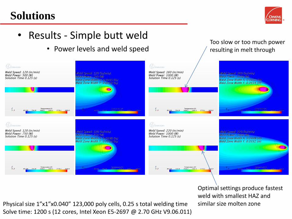
• Results - Simple butt weld • Power levels and weld speed
Physical size 1”x1”x0.040” 123,000 poly cells, 0.25 s total welding time Solve time: 1200 s (12 cores, Intel Xeon E5-2697 @ 2.70 GHz V9.06.011)
Too slow or too much power resulting in melt through
Optimal settings produce fastest weld with smallest HAZ and similar size molten zone
Solutions
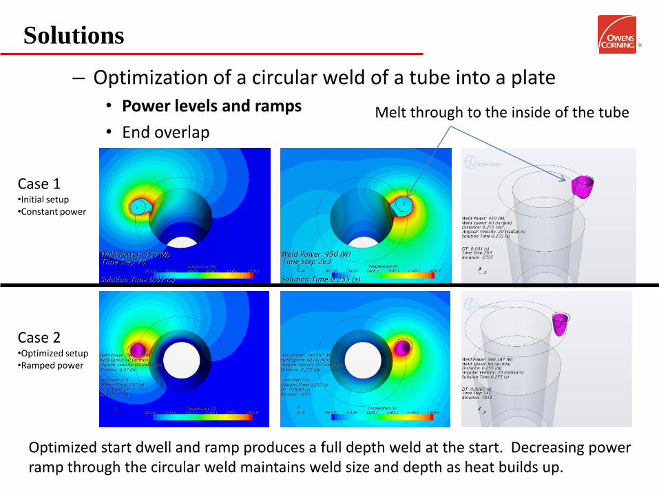
– Optimization of a circular weld of a tube into a plate • Power levels and ramps
• End overlap
Case 1 •Initial setup •Constant power
Case 2 •Optimized setup •Ramped power
Melt through to the inside of the tube
Optimized start dwell and ramp produces a full depth weld at the start. Decreasing power ramp through the circular weld maintains weld size and depth as heat builds up.
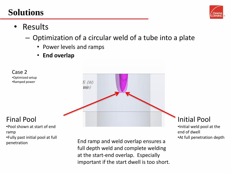
Solutions
• Results – Optimization of a circular weld of a tube into a plate
• Power levels and ramps
• End overlap
Case 2 •Optimized setup •Ramped power
Final Pool •Pool shown at start of end ramp •Fully past initial pool at full penetration
Initial Pool •Initial weld pool at the end of dwell •At full penetration depth
End ramp and weld overlap ensures a full depth weld and complete welding at the start-end overlap. Especially important if the start dwell is too short.
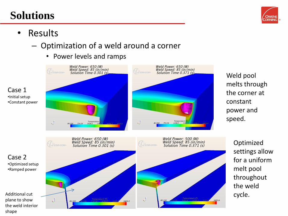
Solutions
• Results – Optimization of a weld around a corner
• Power levels and ramps
Case 1 •Initial setup •Constant power
Case 2 •Optimized setup •Ramped power
Weld pool melts through the corner at constant power and speed.
Optimized settings allow for a uniform melt pool throughout the weld cycle. Additional cut
plane to show the weld interior shape
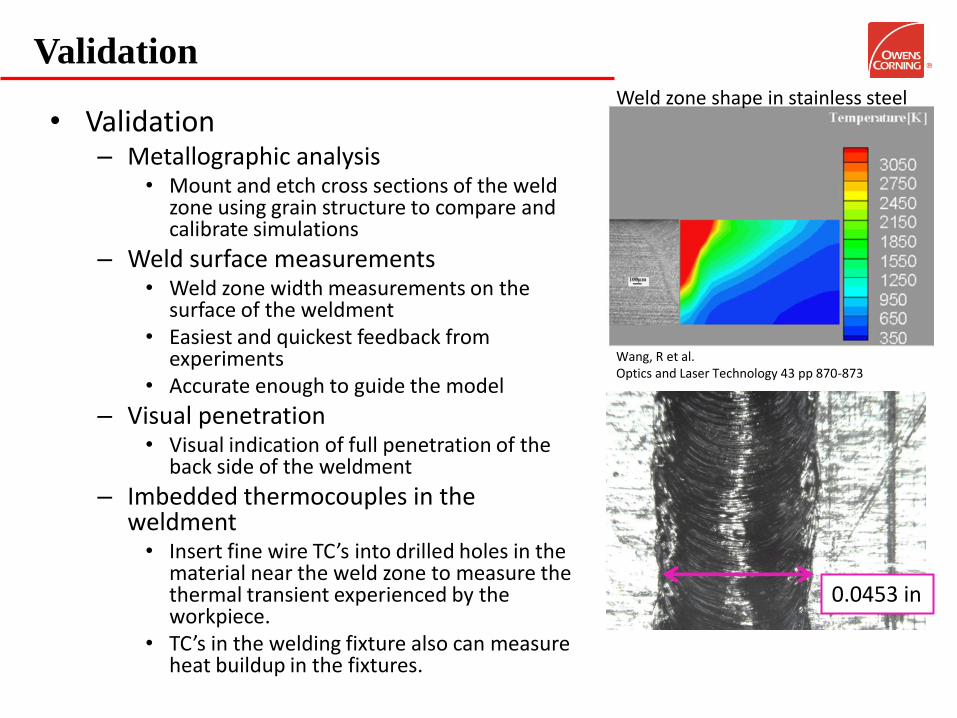
Validation
• Validation – Metallographic analysis
• Mount and etch cross sections of the weld zone using grain structure to compare and calibrate simulations
– Weld surface measurements • Weld zone width measurements on the
surface of the weldment • Easiest and quickest feedback from
experiments • Accurate enough to guide the model
– Visual penetration • Visual indication of full penetration of the
back side of the weldment
– Imbedded thermocouples in the weldment • Insert fine wire TC’s into drilled holes in the
material near the weld zone to measure the thermal transient experienced by the workpiece.
• TC’s in the welding fixture also can measure heat buildup in the fixtures.
Wang, R et al. Optics and Laser Technology 43 pp 870-873
Weld zone shape in stainless steel
0.0453 in
Closing Comments
• Applicability-Review of tested conditions – High melting point metals
• Methodology not tested with lower melting point metals such as ferrous alloys, aluminum alloys etc • Validation must be conducted for each specific alloy
– Thin sections • Methodology was tested with “thin sections” where the focal point and the molten zone nearly or fully
extends to the back surface of the weld
– Laser Power and Keyhole • Sub-kW laser power • 50-micron focal spot • Uniform and non-uniform keyhole vertical power distributions
– Speeds • Less than 200 in/min (0.085 m/s)
– Not meant to replace detailed VOF models of keyhole welding
• Utility – The method does a good job of predicting molten weld pool surface diameter and general
shape with minimal computational effort. – Simulation allows prescription of welding parameters for experimental validation.
• Steady state weld speed and power • Start and end ramp speed and power • Start dwell time and power • Steady state ramping of power and speeds at corners, during circular paths, etc • Overlap of closed weld paths • Heating of weldment and fixture for multiple welds
References
Bibliography • Abderrazak, et al. "Numerical and experimental study of molten pool formation during continous laser welding of AZ91
magnesium alloy." Computational Materials Science, 2009: 858-866. • Cho, et al. "Numerical simulation of molton pool dynamics in high power laser disk welding." Journal of Materials
Processing Technology, 2012: 262-275. • Chukkan, et al. "Simulation of laser butt welding of AISI 316 stainless steel sheet using various heat sources and
experimental validation." Journal of Materials Processing Technology, 2015: 48-59. • Eriksson, I, J. Powell, and A. F. Kaplan. "Melt behavior on the keyhole front during high speed laser welding." Optics and
Lasers in Engineering, 2013: 735-740. • Hu, et al. "Modeling of keyhole dynamics and analysis of energy absorption efficiency based on Fresnel law during deep
penetration laser spot welding." Computational Materials Science, 2015: 48-54. • Kannatey-Asibu, E. Principles of Laser Materials Processing. Hoboken: John Wiley & Sons, Inc., 2009. • Kapalan, A. H. "Modelling the Primary Impact of and Yb:Fibre Laser Beam Profile on the Keyhole Front." Physics Procedia,
2011: 627-637. • Kubiak, et al. "Modelling of laser beam heat source based on experimental research of Yb:YAG laser power distribution."
International Journal of Heat and Mass Transfer, 2015: 679-689. • Vazquez, et al. "Multi-Physical Simulation of Laser Welding." Physics Procedia, 2014: 1334-1342. • Volpp, J., and F. Vollersten. "Analytical modeling of the keyhole including multiple reflections for analysis of the influence of
different laser intensity distributions on keyhole geometry." Physics Procedia, 2013: 460-468. • Wang, R., Y. Lei, and Y. Shi. "Numerical simulation of transient temperature field during laser keyhole welding of 304
stainless steel sheet." Optics and Laser Technology, 2011: 870-873. • StarCCM+ Help V9.06.011