Practical Guide to Psychic Powers: Awaken Your Sixth Sense (Practical Guide Series)

PRACTICAL GUIDELow-voltage power systemsProtection against overvoltages

2
a) b)a) b)
a) b)
Overvoltage caused by lightning
Switching overvoltage
Transient overvoltage
Temporary overvoltage
Overvoltage
230 V, 50 Hz
230 V, 50 Hz
Introduction
Since the 1960s, the purely technical term EMC (elec-tromagnetic compatibility) has become a term com-prising not only safety for appliances and components, but in particular, for their users. Apart from others, it refers to the resistance of devices and equipment to all forms of electromagnetic disturbance, including im-pulse overvoltage and high frequency disturbance. It is thus the suppliers who must increase the resistance of systems today. A correctly designed and installed system of surge protective devices and SALTEK® fi lters can satisfy even the most demanding requirements for the safety of equipment in terms of electromagnetic compatibility.
The current standard of technology offers good protec-tion for electronic and electrical equipment against the effects of dangerous impulse overvoltage, i.e., surge arresters. Equipment can be protected not only against the effects of a destructive impulse that features great energy, but also against the effects of high frequency disturbances. Unprotected electrical wiring, computer and data networks always pose a huge risk for their users. Installing overvoltage protection devices there-fore prevents possible damage. The price of surge arresters is onIy a tiny part of the cost expended on protected equipment and a negligible amount com-pared to the potential damage resulting from a failure or destruction of the technological equipment followed by fi nancial losses.
SALTEK surge arresters are complied Czech and inter-national standards.national standards.
Electronic components damaged by overvoltage
Overvoltage
Overvoltage typesBasically, overvoltage can be classed according to its dura-tion.
Transient overvoltage – short-term changes in voltage: overvoltage that lasts a short time not exceeding several thousandths of a second, oscillating or non-oscillating, usually highly damped, in hundreds of microseconds (see Fig. 1a) – such overvoltage can be successfully eliminated using an SPD.
Temporary overvoltage – long-term changes in voltage:overvoltage with industrial frequency of oscillation and a relatively long duration– in milliseconds or less (see Fig. 1b)– such overvoltage cannot be eliminated by means of an
SPD.
Fig. 1a
Fig. 1b

Practical Guide - Low-voltage power systems
3
L
N
L
N
L
N
Short-term changes in voltage, i.e. transient overvoltage can be classed in several groups according to the origin:– differential mode of overvoltage: overvoltage between
live conductors (L1-L2, L-N with LV supply, a-b with tele-communications…), such overvoltage occurs as a result of technological events – e.g. switching of non-linear loads (motors, refrigerators,...). These are particularly dangerous for electronic equipment, sensitive hardware-like control systems, computers and their software utilities, etc. (see Fig. 2)
– common mode of overvoltage: overvoltage between the neutral conductor and earthing conductor (L-PE, N-PE in LV, a/b-PE in telecommunications…) that results from at-mospheric events – a lightning strike. Such overvoltages are particularly dangerous for technology, the frame of which is earthed (insulation breakdown). (see Fig. 3)
An SPD in the supply network will be selected according to the type of respective overvoltage.
Overvoltage wave parameters
Differential mode (switching) of overvoltage
Common mode (lightning) of overvoltage
Impulse front time
L
N
Common mode
overvoltage
Test impulse 10/350 µs simulates a lightning strike and SPD type 1 and SPD type 1+2 are tested according to it
i (kA)
508/20 μs 10/350 μs
t (μs)
25
50
25
20 10 3508t (μs)
i (kA)
Impulse tail time
Fig. 2
Fig. 3
Fig. 4

4
Protection of technology against overvoltage
Supply networks – SPD connection principles on how to connect SPDs
Test impulse 8/20 µs simulates technological overvoltage and SPD type 2 and SPD type 3 are tested according to it.
Fig. 5
Comparison of the energy of testing impulses 10/350 µs and 8/20 µs
The principle of surge protective devices is based on the equipotential bonding. This is conditioned by the effective equalising potential in the whole building. It is only possible if the whole building is thoroughly provided with equipo-tential bonding and it should be connected to the earthing electrode.
If a building features external lightning protection (LPS), both the down conductor as well as the protective con-ductor of the supply network should be connected to the earthing conductor. This is shown in the following chapter.
An SPD in power supply networks should be connected in two connection modes – mode x+0 and mode x+1.
The x+0 connection mode is designated 3+0 (TN-C) or 4+0 (TN-S) for three-phase power supply and 1+0 (TN-C) or 2+0 (TN-S) for single-phase power supply. Such mode is benefi cial in eliminating common mode of overvoltage.
The x+1 connection mode is designated 3+1 for three-phase power supply and 1+1 for single-phase power supply. It can-not be used in the TN-C supply network. It is advantageous to use it to eliminate differential mode of overvoltage.
Zkušební proudové vlny 10/350 μs a 8/20 μs
•
••
10/350 µs
8/20 µs
Isn
(kA)
Lightning arresters SPD type 1
Surge arresters SPD type 2Surge arresters SPD type 2
i (kA)
508/20 μs
t (μs)
25
208
Fig. 5
Fig. 6

Practical Guide - Low-voltage power systems
5
*F3
Podružný rozváděč (1)
SPD typ 2
SPD typ 2
Vstupní část instalace
L1
L2
L3
N
PE
F1RC
D
Hlavní zemní přípojnice
Exte
rní o
chra
na p
roti
bles
ku
Hlavní rozváděč
SPD typ 1 nebo 1+2
Podružný rozváděč (2)
SPD typ 2
Jemná ochrana
SPD typ 3
63 A
16 A
16 A
LPZ 0 LPZ 2LPZ 1 LPZ 2
Lokální zemní přípojnice Lokální zemní přípojnice
*F4*F2
LPZ 2
Vstupní část instalace
L1
L2
L3
N
PE
F1
RCD
Hlavní zemní přípojnice
Exte
rní o
chra
na p
roti
bles
ku
Hlavní rozváděč
SPD typ 1 nebo 1+2
Podružný rozváděč
SPD typ 2
Jemná ochrana
SPD typ 3
63 A
16 A
16 A
LPZ 0 LPZ 1 LPZ 2
Lokální zemní přípojnice
*F3
L1
L2
L3
N
PEN PE
F1
*F2
Vstupní část instalace
L1
L2
L3
PEN
F1
Hlavní zemní přípojnice
Exte
rní o
chra
na p
roti
bles
ku
Hlavní rozváděč
SPD typ 1 nebo 1+2LPZ 0
*F2
RCD
SPD typ 3LPZ 1
*F3
*F3
Podružný rozváděč
Lokální zemní přípojnice
*F4
*F2
63 A
16 A
16 A
Jemná ochrana
63 A
16 A
16 A
An SPD type 3 is always mounted close to the equipment to be protected.
TN-C-S systemIn a TN-C-S supply network, the SPD located before the point from which the PEN conductor separates to the N and PE conductors should always be connected in the x+0 mode. Behind the point of separation, an SPD type 2 can be connected in both x+1 mode or x+0, with the same principle to be followed as in a TN-S network, i.e., such type of connection should be chosen to better suit the re-spective situation.
*F3
L1
L2
L3
N
PE
F1
RCD
63 A
16 A
16 A
*F4*F2
L1
L2
L3
N
PE
F1
RCD
63 A
16 A
16 A
*F3
L1
L2
L3
N
EPNEP
F1
*F2
L1
L2
L3
PEN
F1
*F2
RCD
*F3
*F3
*F4
*F2
63 A
16 A
16 A
63 A
16 A
16 A
* Additional protection of SPD – see page 7
LPZ 0 LPZ 1 LPZ 2 LPZ 2SPD type 1 or 1+2Main distribution board
SPD type 2Subsidiary distribution board (1)
SPD type 2Subsidiary distribution board (2)
SPD type 3Fine protectionOrigin of the
installation
Exte
rnal
ligh
tnin
g pr
otec
tion
Main earthing bonding bar
Local earthing bonding bar Local earthing bonding bar
LPZ 0 LPZ 1 LPZ 2 LPZ 2Origin of the installation
TN-S systemAn SPD type 1 or SPD type 1 and 2 should be located at the incoming supply to the building (mostly in the main distribution board). These SPDs are mainly intended to restrict lightning electromagnetic impulses (lightning strikes) and therefore are installed in the x+0 design, i.e., all live conductors (L1, L2, L3 and N) against ground (PE).
An SPD type 2 should be located in a subsidiary distribution board. In such supply networks, an SPD type 2 can either be connected in the x + 0 mode (to eliminate longitudinal – light-ning electromagnetic impulse) or in the x + 1 mode (to restrict overvoltage in the equipment).
In a TN-S supply network, connection of a type 2 SPD must follow the type of overvoltage that will prevail in the supply network. Consequently, in industrial operations, where a great number of switching overvoltage occurs, it is more advanta-geous to connect an SPD type 2 in the x + 1 mode, while in administrative and residential buildings it is better to connect an SPD type 2 in the x + 0 mode.
TN-S system
TN-C-S system
Equi
pmen
t (te
chno
logy
)Eq
uipm
ent (
tech
nolo
gy)
* Additional protection of SPD – see page 7Main earthing
bonding barLocal earthing bonding bar Local earthing bonding bar
Exte
rnal
ligh
tnin
g pr
otec
tion
SPD type 1 or 1+2Main distribution board
SPD type 2Subsidiary distribution board (1)
SPD type 2Subsidiary distribution board (2)
SPD type 3Fine protection
Fig. 7
Fig. 8

6
*F3
L1
L2
L3
N
PE
F1
RCD
63 A
16 A
16 A
*F4*F2
L1
L2
L3
N
PE
F1
RCD
63 A
16 A
16 A
*F3
L1
L2
L3
N
EPNEP
F1
*F2
L1
L2
L3
PEN
F1
*F2
RCD
*F3
*F3
*F4
*F2
63 A
16 A
16 A
63 A
16 A
16 A
* předjišťování SPD – viz str. 7
*F3
L1
L2
L3
N
PE
F1
RCD
63 A
16 A
16 A
*F4*F2
L1
L2
L3
N
PE
F1
RCD
63 A
16 A
16 A
*F3
L1
L2
L3
N
EPNEP
F1
*F2
L1
L2
L3
PEN
F1
*F2
RCD
*F3
*F3
*F4
*F2
63 A
16 A
16 A
63 A
16 A
16 A
TN-C systemIn a TN-C supply network, an SPD can only be connected in the x+0 mode. In an SPD type 3, manufactured in the x+1 connection mode, the N conductor (blue) as well as the PE conductor (yellow-green) should always be connected to the PEN conductor.
TT systemFor a TT supply network, in which only neutral conductors L1, L2, L3 are routed from the power source, all levels of SPD should always be connected in the x+1 mode.
* Additional protection of SPD – see page 7
LPZ 0 LPZ 1 LPZ 2SPD type 1 or 1+2Main distribution board
SPD type 2Subsidiary distribution board
SPD type 3Fine protectionOrigin of the
installation
Exte
rnal
ligh
tnin
g pr
otec
tion
Main earthing bonding bar
Local earthing bonding bar
Equi
pmen
t (te
chno
logy
)LPZ 0 LPZ 1 LPZ 2
Origin of the installation
TN-C system
TT system
překlad
SPD type 1 or 1+2Main distribution board
SPD type 2Subsidiary distribution board
SPD type 3Fine protection
* Additional protection of SPD – see page 7
Exte
rnal
ligh
tnin
g pr
otec
tion
Main earthing bonding bar
Local earthing bonding bar
Equi
pmen
t (te
chno
logy
)
obr. 9
obr. 10

Practical Guide - Low-voltage power systems
7
Principle of overcurrent protection of SPD
a) protection priority principle – an SPD should be provid-ed with additional protection in this case only if the value of the line protection (F1 fuse) is higher than the value of the respective SPD shown in the catalogue (F2 fuse) and the SPD protection always has the value shown in the manufacturer´s catalogue (parameter – maximum additional protection).
An example of back-up fuse for SPD – FLP-B+C MAXI V – in different supply networks.The catalogue value of maximum back-up fuse for FLP-B+C MAXI V is 250 A, and 125 A for the „V“ connection.
TN-S
For overcurrent protection of SPD it is important to consider whether we should follow the protection priority principle, which is used in most installations, or the power supply priority principle.
TN-C
TN-C-S
FLP-B+C MAXI VSPD T1 T2
červená – porucha red – defect
250 A
Uc: 260 V~Iimp: 25 kAIn: 30 kAImax: 60 kAUp: < 1,5 kV
FLP-B+C MAXI VSPD T1 T2
červená – porucha red – defect
250 A
Uc: 260 V~Iimp: 25 kAIn: 30 kAImax: 60 kAUp: < 1,5 kV
FLP-B+C MAXI VSPD T1 T2
červená – porucha red – defect
250 A
Uc: 260 V~Iimp: 25 kAIn: 30 kAImax: 60 kAUp: < 1,5 kV
FLP-B+C MAXI VSPD T1 T2
červená – porucha red – defect
250 A
Uc: 260 V~Iimp: 25 kAIn: 30 kAImax: 60 kAUp: < 1,5 kV
F1 ≤ 125 A
FLP-B+C MAXI VSPD T1 T2
červená – porucha red – defect
250 A
Uc: 260 V~Iimp: 25 kAIn: 30 kAImax: 60 kAUp: < 1,5 kV
FLP-B+C MAXI VSPD T1 T2
červená – porucha red – defect
250 A
Uc: 260 V~Iimp: 25 kAIn: 30 kAImax: 60 kAUp: < 1,5 kV
FLP-B+C MAXI VSPD T1 T2
červená – porucha red – defect
250 A
Uc: 260 V~Iimp: 25 kAIn: 30 kAImax: 60 kAUp: < 1,5 kV
FLP-B+C MAXI VSPD T1 T2
červená – porucha red – defect
250 A
Uc: 260 V~Iimp: 25 kAIn: 30 kAImax: 60 kAUp: < 1,5 kV
FLP-B+C MAXI VSPD T1 T2
červená – porucha red – defect
250 A
Uc: 260 V~Iimp: 25 kAIn: 30 kAImax: 60 kAUp: < 1,5 kV
FLP-B+C MAXI VSPD T1 T2
červená – porucha red – defect
250 A
Uc: 260 V~Iimp: 25 kAIn: 30 kAImax: 60 kAUp: < 1,5 kV
FLP-B+C MAXI VSPD T1 T2
červená – porucha red – defect
250 A
Uc: 260 V~Iimp: 25 kAIn: 30 kAImax: 60 kAUp: < 1,5 kV
F1 ≤ 125 A
FLP-B+C MAXI VSPD T1 T2
červená – porucha red – defect
250 A
Uc: 260 V~Iimp: 25 kAIn: 30 kAImax: 60 kAUp: < 1,5 kV
FLP-B+C MAXI VSPD T1 T2
červená – porucha red – defect
250 A
Uc: 260 V~Iimp: 25 kAIn: 30 kAImax: 60 kAUp: < 1,5 kV
FLP-B+C MAXI VSPD T1 T2
červená – porucha red – defect
250 A
Uc: 260 V~Iimp: 25 kAIn: 30 kAImax: 60 kAUp: < 1,5 kV
FLP-B+C MAXI VSPD T1 T2
červená – porucha red – defect
250 A
Uc: 260 V~Iimp: 25 kAIn: 30 kAImax: 60 kAUp: < 1,5 kV
FLP-B+C MAXI VSPD T1 T2
červená – porucha red – defect
250 A
Uc: 260 V~Iimp: 25 kAIn: 30 kAImax: 60 kAUp: < 1,5 kV
FLP-B+C MAXI VSPD T1 T2
červená – porucha red – defect
250 A
Uc: 260 V~Iimp: 25 kAIn: 30 kAImax: 60 kAUp: < 1,5 kV
PE
N
F1 ≤ 125 A
FLP-B+C MAXI VSPD T1 T2
červená – porucha red – defect
250 A
Uc: 260 V~Iimp: 25 kAIn: 30 kAImax: 60 kAUp: < 1,5 kV
FLP-B+C MAXI VSPD T1 T2
červená – porucha red – defect
250 A
Uc: 260 V~Iimp: 25 kAIn: 30 kAImax: 60 kAUp: < 1,5 kV
FLP-B+C MAXI VSPD T1 T2
červená – porucha red – defect
250 A
Uc: 260 V~Iimp: 25 kAIn: 30 kAImax: 60 kAUp: < 1,5 kV
PE
N
Parallel connection “V” (series) connection1
2
3
F1 > 250 A → F2F1 ≤ 250 A → F2F1 > 125 AF1 ≤ 125 A
F1 > 250 A → F2F1 ≤ 250 A → F2F1 > 125 AF1 ≤ 125 A
F1 > 250 A → F2F1 ≤ 250 A → F2F1 > 125 AF1 ≤ 125 A
8
TN-C
F2' ≥ 160 A → F2F2' < 160 A → F2'
F2' ≥ 160 A → F2F2' < 160 A→ F2'
F2' ≥ 160 A → F2F2' < 160 A → F2'
TN-S
TN-C-S
PENPEN
FLP-
12,5
Vče
rven
ápo
ruch
a re
dde
fect
SPD
T1
T2
FLP-
12,5
Vče
rven
ápo
ruch
a re
dde
fect
SPD
T1
T2
FLP-
12,5
Vče
rven
ápo
ruch
a re
dde
fect
SPD
T1
T2
L1 L2 L3
L3L2L1
F2 = 160 A
F1 > 160 A
PENPEN
FLP-
12,5
Vče
rven
ápo
ruch
a re
dde
fect
SPD
T1
T2
FLP-
12,5
Vče
rven
ápo
ruch
a re
dde
fect
SPD
T1
T2
FLP-
12,5
Vče
rven
ápo
ruch
a re
dde
fect
SPD
T1
T2
L1 L2 L3
L3L2L1
F2'
F1
PENPEN
FLP-
12,5
Vče
rven
ápo
ruch
a re
dde
fect
SPD
T1
T2
FLP-
12,5
Vče
rven
ápo
ruch
a re
dde
fect
SPD
T1
T2
FLP-
12,5
Vče
rven
ápo
ruch
a re
dde
fect
SPD
T1
T2
L1 L2 L3
L3L2L1
F2'
PE PE
FLP-
12,5
Vče
rven
ápo
ruch
a re
dde
fect
SPD
T1
T2
FLP-
12,5
Vče
rven
ápo
ruch
a re
dde
fect
SPD
T1
T2
FLP-
12,5
Vče
rven
ápo
ruch
a re
dde
fect
SPD
T1
T2
FLP-
12,5
Vče
rven
ápo
ruch
a re
dde
fect
SPD
T1
T2
L1 L2 L3 N
NL3L2L1
F2 = 160 A
F1 > 160 A
PE PE
FLP-
12,5
Vče
rven
ápo
ruch
a re
dde
fect
SPD
T1
T2
FLP-
12,5
Vče
rven
ápo
ruch
a re
dde
fect
SPD
T1
T2
FLP-
12,5
Vče
rven
ápo
ruch
a re
dde
fect
SPD
T1
T2
FLP-
12,5
Vče
rven
ápo
ruch
a re
dde
fect
SPD
T1
T2
L1 L2 L3 N
NL3L2L1
F2'
F1
PE PE
FLP-
12,5
Vče
rven
ápo
ruch
a re
dde
fect
SPD
T1
T2
FLP-
12,5
Vče
rven
ápo
ruch
a re
dde
fect
SPD
T1
T2
FLP-
12,5
Vče
rven
ápo
ruch
a re
dde
fect
SPD
T1
T2
FLP-
12,5
Vče
rven
ápo
ruch
a re
dde
fect
SPD
T1
T2
L1 L2 L3 N
NL3L2L1
F2'
PE
N
PENPEN
FLP-
12,5
Vče
rven
ápo
ruch
a re
dde
fect
SPD
T1
T2
FLP-
12,5
Vče
rven
ápo
ruch
a re
dde
fect
SPD
T1
T2
FLP-
12,5
Vče
rven
ápo
ruch
a re
dde
fect
SPD
T1
T2
L1 L2 L3
L3L2L1
F2 = 160 A
F1 > 160 A
PENPEN
FLP-
12,5
Vče
rven
ápo
ruch
a re
dde
fect
SPD
T1
T2
FLP-
12,5
Vče
rven
ápo
ruch
a re
dde
fect
SPD
T1
T2
FLP-
12,5
Vče
rven
ápo
ruch
a re
dde
fect
SPD
T1
T2
L1 L2 L3
L3L2L1
F2'
F1
PENPEN
FLP-
12,5
Vče
rven
ápo
ruch
a re
dde
fect
SPD
T1
T2
FLP-
12,5
Vče
rven
ápo
ruch
a re
dde
fect
SPD
T1
T2
FLP-
12,5
Vče
rven
ápo
ruch
a re
dde
fect
SPD
T1
T2
L1 L2 L3
L3L2L1
F2'
PE
N
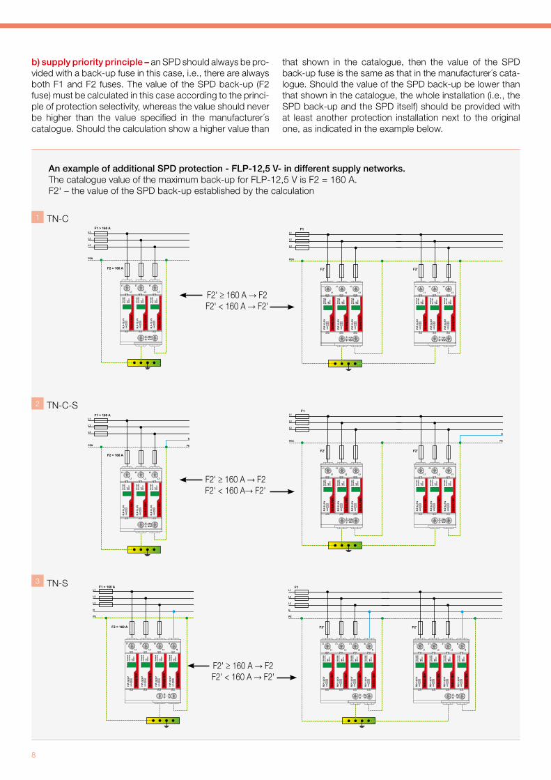
b) supply priority principle – an SPD should always be pro-vided with a back-up fuse in this case, i.e., there are always both F1 and F2 fuses. The value of the SPD back-up (F2 fuse) must be calculated in this case according to the princi-ple of protection selectivity, whereas the value should never be higher than the value specified in the manufacturer´s catalogue. Should the calculation show a higher value than
that shown in the catalogue, then the value of the SPD back-up fuse is the same as that in the manufacturer´s cata-logue. Should the value of the SPD back-up be lower than that shown in the catalogue, the whole installation (i.e., the SPD back-up and the SPD itself) should be provided with at least another protection installation next to the original one, as indicated in the example below.
An example of additional SPD protection - FLP-12,5 V- in different supply networks.The catalogue value of the maximum back-up for FLP-12,5 V is F2 = 160 A.F2‘ – the value of the SPD back-up established by the calculation
1
2
3

Practical Guide - Low-voltage power systems
9
SPD dimensioning
Only the SPD type 1 should be dimensioned. Dimensioning of the SPD type 1 should be based on the calculation of the lightning protection level (LPL) for the lightning protec-tion system (LPS). The table from CLC/TS 50539-12 below
Table 1 Note: CT1 – SPD connected in the x+0 mode; CT2 – SPD connected in the x+1 mode
CT1 – TN-C CT1 – TN-S CT2
shows minimum values of the discharge lightning strike cur-rent to the pole considering the lightning protection (LPL) class of the building for the SPD type 1.
If the LPL value is not known, the worse scenario is anticipated Low voltage networks
LPL
Maximum current
corresponding to LPL
Number of conductors
(n)
TT TN-C TN-SIT
without neutral conductor
ITwith neutral conductor
Connection mode Connection mode Connection mode
CT1 CT2 CT1 CT2 CT1 CT2
L-PEN-PE L-N N-PE L-PEN
L-PEN-PE L-N N-PE L-PE L-N N-PE
1 or unknown 200 kA
Iimp (kA)
5 N/A N/A N/A N/A 20.0 20.0 80.0 N/A N/A N/A
4 25.0 25.0 100.0 25.0 N/A N/A N/A N/A 25.0 100.0
3 N/A N/A N/A N/A 33,3 33,3 66,7 33,3 N/A N/A
2 50.0 50.0 100.0 50.0 N/A N/A N/A N/A 50.0 100.0
2 150 kA
Iimp (kA)
5 N/A N/A N/A N/A 15,0 15,0 60,0 N/A N/A N/A
4 18.8 18.8 75.0 18.8 N/A N/A N/A N/A 18.8 75.0
3 N/A N/A N/A N/A 25,0 25,0 50,0 25,0 N/A N/A
2 37.5 37.5 75.0 37.5 N/A N/A N/A N/A 37.5 75.0
3 or 4 100 kA
Iimp (kA)
5 N/A N/A N/A N/A 10,0 10,0 40,0 N/A N/A N/A
4 12.5 12.5 50.0 12.5 N/A N/A N/A N/A 12.5 50.0
3 N/A N/A N/A N/A 16.7 16.7 33.3 16.7 N/A N/A
2 25.0 25.0 50.0 25.0 N/A N/A N/A N/A 25.0 50.0
10
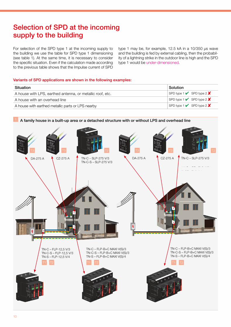
For selection of the SPD type 1 at the incoming supply to the building we use the table for SPD type 1 dimensioning (see table 1). At the same time, it is necessary to consider the specifi c situation. Even if the calculation made according to the previous table shows that the Impulse current of SPD
type 1 may be, for example, 12.5 kA in a 10/350 µs wave and the building is fed by external cabling, then the probabil-ity of a lightning strike in the outdoor line is high and the SPD type 1 would be under-dimensioned.
Variants of SPD applications are shown in the following examples:
Selection of SPD at the incoming supply to the building
1
TN-C – SLP-275 V/3TN-C-S – SLP-275 V/3TN-S – SLP-275 V/3+1or SLP-275 V/4
DA-275 A CZ-275 A TN-C – SLP-275 V/3TN-C-S – SLP-275 V/3TN-S – SLP-275 V/3+1or SLP-275 V/4
DA-275 A CZ-275 A
T1 T2T1 T2T1 T2
T2T3T3T3T3 T2
TN-C-S – SLP-275 V/3TN-C-S – SLP-275 V/3TN-S – SLP-275 V/3+1or SLP-275 V/4
TN-S – SLP-275 V/3+1or SLP-275 V/4
T1 T2T1 T2
Situation Solution
A house with LPS, earthed antenna, or metallic roof, etc. SPD type 1 SPD type 2
A house with an overhead line SPD type 1 SPD type 2
A house with earthed metallic parts or LPS nearby SPD type 1 SPD type 2
A family house in a built-up area or a detached structure with or without LPS and overhead line
TN-C – FLP-B+C MAXI V(S)/3TN-C-S – FLP-B+C MAXI V(S)/3TN-S – FLP-B+C MAXI V(S)/4
TN-C – FLP-12,5 V/3TN-C-S – FLP-12,5 V/3TN-S – FLP-12,5 V/4
TN-C – FLP-B+C MAXI V(S)/3TN-C-S – FLP-B+C MAXI V(S)/3TN-S – FLP-B+C MAXI V(S)/4
Practical Guide - Low-voltage power systems
11
TN-C – FLP-12,5 V/3TN-C-S – FLP-12,5 V/3TN-S – FLP-12,5 V/4
TN-C – SLP-275 V/3TN-C-S – SLP-275 V/3TN-S – SLP-275 V/3+1 or SLP-275 V/4
DA-275 A CZ-275 A
TN-C – FLP-B+C MAXI V(S)/3TN-C-S – FLP-B+C MAXI V(S)/3TN-S – FLP-B+C MAXI V(S)/4
TN-C – SLP-275 V/3TN-C-S – SLP-275 V/3TN-S – SLP-275 V/3+1 or SLP-275 V/4
DA-275 A CZ-275 A
TN-C – FLP-12,5 V/3TN-C-S – FLP-12,5 V/3TN-S – FLP-12,5 V/4
TN-C – FLP-12,5 V/3TN-C-S – FLP-12,5 V/3TN-S – FLP-12,5 V/4
3
T1 T2T1 T2
T2T3T3T2T3T3
T2T1T2T1
T2T1
or SLP-275 V/4 or SLP-275 V/4
TN-C – FLP-B+C MAXI V(S)/3TN-C-S – FLP-B+C MAXI V(S)/3TN-S – FLP-B+C MAXI V(S)/4
TN-C – FLP-12,5 V/3
A family house in a built-up area without LPS and with a underground cable connection
A detached family house with or without LPS, with a underground cable connection
T2T3T3T2T3T3
TN-C – SLP-275 V/3TN-C-S – SLP-275 V/3TN-S – SLP-275 V/3+1 or SLP-275 V/4
DA-275 A CZ-275 ATN-C – SLP-275 V/3TN-C-S – SLP-275 V/3TN-S – SLP-275 V/3+1
or SLP-275 V/4
DA-275 A CZ-275 A
2

12
Terrace houses with a common LPS and overhead line
TN-C – SLP-275 V/3TN-C-S – SLP-275 V/3TN-S – SLP-275 V/3+1or SLP-275 V/4
DA-275 A CZ-275 A
TN-C – FLP-B+C MAXI V(S)/3TN-C-S – FLP-B+C MAXI V(S)/3TN-S – FLP-B+C MAXI V(S)/4
TN-C – FLP-12,5 V/3TN-C-S – FLP-12,5 V/3TN-S – FLP-12,5 V/4
Terrace houses with a common LPS and a underground cable connection5
T1 T2
T1 T2
T3 T3 T2
4
TN-C – SLP-275 V/3TN-C-S – SLP-275 V/3TN-S – SLP-275 V/3+1or SLP-275 V/4
DA-275 A CZ-275 A
T3 T3 T2
Practical Guide - Low-voltage power systems
13
Blocks of fl ats with a underground cable connection with the possibility to install an SPD type 1 upstream of power meter
TN-C – FLP-12,5 V/3TN-C-S – FLP-12,5 V/3TN-S – FLP-12,5 V/4
CZ-275 A
DA-275 A
TN-C – FLP-B+C MAXI V(S)/3TN-C-S – FLP-B+C MAXI V(S)/3TN-S – FLP-B+C MAXI V(S)/4
TN-C – SLP-275 V/3TN-C-S – SLP-275 V/3TN-S – SLP-275 V/3+1or SLP-275 V/4
CZ-275 A
DA-275 A
TN-C – FLP-B+C MAXI V(S)/3TN-C-S – FLP-B+C MAXI V(S)/3TN-S – FLP-B+C MAXI V(S)/4
Blocks of fl ats with a underground cable connection with the possibility to install an SPD type 1 upstream of power meter
CZ-275 A
TN-C – FLP-12,5 V/1TN-C-S – FLP-12,5 V/1TN-S – FLP-12,5 V/2
TN-C –SLP-275 V/1TN-C-S –SLP-275 V/1TN-S – SLP-275 V/1+1or SLP-275 V/2
CZ-275 A
T1 T2
7
T3 T3
T2
T2
T3T3
6
T1 T2
T1 T2
T1 T2
Blocks of fl ats with a underground cable connection without the possibility to install an SPD type 1 upstream of power meter

14
orDA-275 A CZ-275 A
TN-C – SLP-275 V/3TN-C-S – SLP-275 V/3TN-S – SLP-275 V/3+1or SLP-275 V/4
TN-C – SLP-275 V/3TN-C-S – SLP-275 V/3TN-S – SLP-275 V/3+1or SLP-275 V/4
TN-C – FLP-B+C MAXI V(S)/3TN-C-S – FLP-B+C MAXI V(S)/3TN-S – FLP-B+C MAXI V(S)/4
Administrative building
T1T2
T3T3
8
T2
T2

Practical Guide - Low-voltage power systems
15
10
TN-C – FLP-B+C MAXI V(S)/3TN-C-S – FLP-B+C MAXI V(S)/3TN-S – FLP-B+C MAXI V(S)/4
or or
a
TN-C – 3 pce. FLP-SG50 V(S)/1TN-C-S – 3 pce. FLP-SG50 V(S)/1TN-S – 4 pce. FLP-SG50 V(S)/1
T1
TN-C – SLP-275 V/3TN-C-S – SLP-275 V/3TN-S – SLP-275 V/4
T2
TN-C – FLP-25-T1-V(S)/3TN-C-S – FLP-25-T1-V(S)/3TN-S – FLP-25-T1-V(S)/4
T1
TN-C – 3 pce. FLP-SG50 V(S)/1TN-C-S – 3 pce. FLP-SG50 V(S)/1TN-S – 4 pce. FLP-SG50 V(S)/1
T1
T1
9
T2
A commercial building
A commercial building of special importance
16
TN-C – FLP-B+C MAXI V(S)/3TN-C-S – FLP-B+C MAXI V(S)/3TN-S – FLP-B+C MAXI V(S)/4
TN-C – SLP-275 V/3TN-C-S – SLP-275 V/3TN-S – SLP-275 V/4
DA-275 A
CZ-275 A
TN-S – DA-275 V/3+1TN-S – DA-275 V/3+1
TN-C-S – SLP-275 V/3TN-S – SLP-275 V/4
TN-S – DA-275 DF25
TN-S – DA-275 DF16
TN-S – SLP-275 V/3+1TN-S – SLP-275 V/3+1
TN-C – SLP-275 V/3TN-C-S – SLP-275 V/3TN-S – SLP-275 V/4
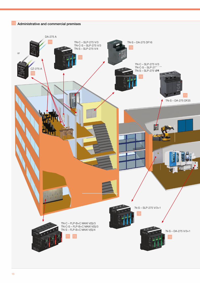
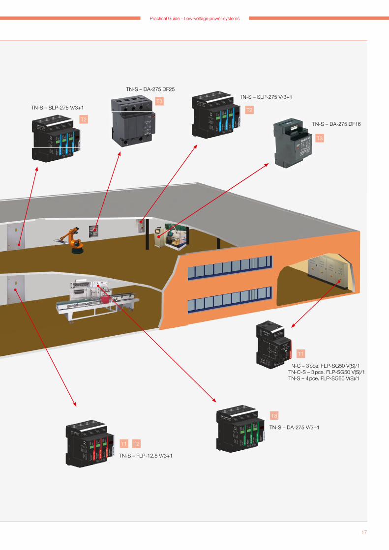
Administrative and commercial premises
T2
T3
T3
T3
T2
T3
T3
T2
T1 T2
11
or
Practical Guide - Low-voltage power systems
17
TN-C – 3 pce. FLP-SG50 V(S)/1TN-C-S – 3 pce. FLP-SG50 V(S)/1TN-S – 4 pce. FLP-SG50 V(S)/1
TN-C – 3 pce. FLP-SG50 V(S)/1
TN-S – SLP-275 V/3+1
TN-S – DA-275 V/3+1
TN-S – DA-275 DF16
TN-S – DA-275 DF25TN-S – SLP-275 V/3+1TN-S – SLP-275 V/3+1
T3
T1
T3
T2
T3
T2
TN-S – FLP-12,5 V/3+1
T1 T2

18
T1
12 A building with LPS and air conditioner or heating cables in gutters
Double--conductor supply
Three--conductor supply
TN-C – 1 pce. FLP-SG50 V(S)/1TN-C-S – 1 pce. FLP-SG50 V(S)/1
TN-S – 2 pce. FLP-A35
TN-C – FLP-B+C MAXI V(S)/3TN-C-S – FLP-B+C MAXI V(S)/3TN-S – FLP-B+C MAXI V(S)/4
DA-275 A or CZ-275 A
TN-C – FLP-12,5 V/1TN-C-S – FLP-12,5 V/1TN-S – FLP-12,5 V/2
-conductor
A house with a single-phase power supply and LPS (LPL I)
T1
T3 T3
T1 T2
T1 T2
1 2
13
Practical Guide - Low-voltage power systems
19
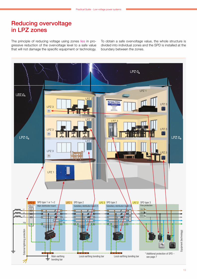
The principle of reducing voltage using zones lies in pro-gressive reduction of the overvoltage level to a safe value that will not damage the specifi c equipment or technology.
Reducing overvoltage in LPZ zones
To obtain a safe overvoltage value, the whole structure is divided into individual zones and the SPD is installed at the boundary between the zones.
LPZ 0A
LPZ 0BLPZ 0B
LPZ 0A
LPZ 0A
LPZ 0BLPZ 0B
LPZ 0A
LPZ 2
LPZ 2
LPZ 2
LPZ 1
LPZ 3
LPZ 3
LPZ 3
LPZ 1
LPZ 3
LPZ 3
LPZ 3
LPZ 3LPZ 3
*F3
L1
L2
L3
N
PE
F1
RCD
63 A
16 A
16 A
*F4*F2
L1
L2
L3
N
PE
F1
RCD
63 A
16 A
16 A
*F3
L1
L2
L3
N
EPNEP
F1
*F2
L1
L2
L3
PEN
F1
*F2
RCD
*F3
*F3
*F4
*F2
63 A
16 A
16 A
63 A
16 A
16 A
LPZ 0 LPZ 1 LPZ 2 LPZ 2Origin of the installation
* Additional protection of SPD – see page 7
SPD type 1 or 1+2Main distribution board
SPD type 2Subsidiary distribution board (1)
SPD type 2Subsidiary distribution board (2)
SPD type 3Fine protection
Exte
rnal
ligh
tnin
g pr
otec
tion
Main earthing bonding bar
Local earthing bonding bar Local earthing bonding bar
Equi
pmen
t (te
chno
logy
)

20
a
b c
a + b ≤ 0,5 m c ≤ 0,5 m
b
a
UW
∆U1
Up
∆U2
OCPOCP
SPDSPD
SPD mounting – principles
Principle 1 – length of connecting conductors If you want to protect equipment, there are several things to remember when installing an SPD, i.e., apart from its diverting ability, it is the maximum value of voltage protec-tive level to be withheld by the equipment at its terminals considering the installation method. Protection level Up and the drop in voltage at the supply conductors ∆U must not exceed the withstand voltage at the terminals of the equip-ment.
Fig. 11 clearly shows that the aggregate protection level is given by adding partial reductions in voltage, while such a sum must not exceed the withstand voltage Uw at the ter-minals of the equipment.
where Uw … withstand voltage Up … voltage protection level ∆U1, ∆U2 … reduction in voltage at the
supply conductor.
The impedance of supply conductors for high frequency currents is approximately 1 µH per 1 m of conductor length.
The voltage drop in this conductor is given by the formula:
So with a steepness of the pulse rise time of 1 kA/µs, there is a reduction of 1,000 V per 1 m of length, which is added to the protection voltage level of the SPD itself. With the total length of supply conductors being 0.5 m, 500 V will be added to the protection voltage level Up. Consequently, the length of the supply conductors must be as short as possi-ble and should not exceed an aggregate length of 0.5 m, as shown in the following fi gures (Fig. 12 and Fig. 13), depicting the connection options.
∆U = L × di/dt
Uw > Up + ∆U1 + ∆U2
Fig. 11
Fig. 12 Fig. 13
Practical Guide - Low-voltage power systems
21
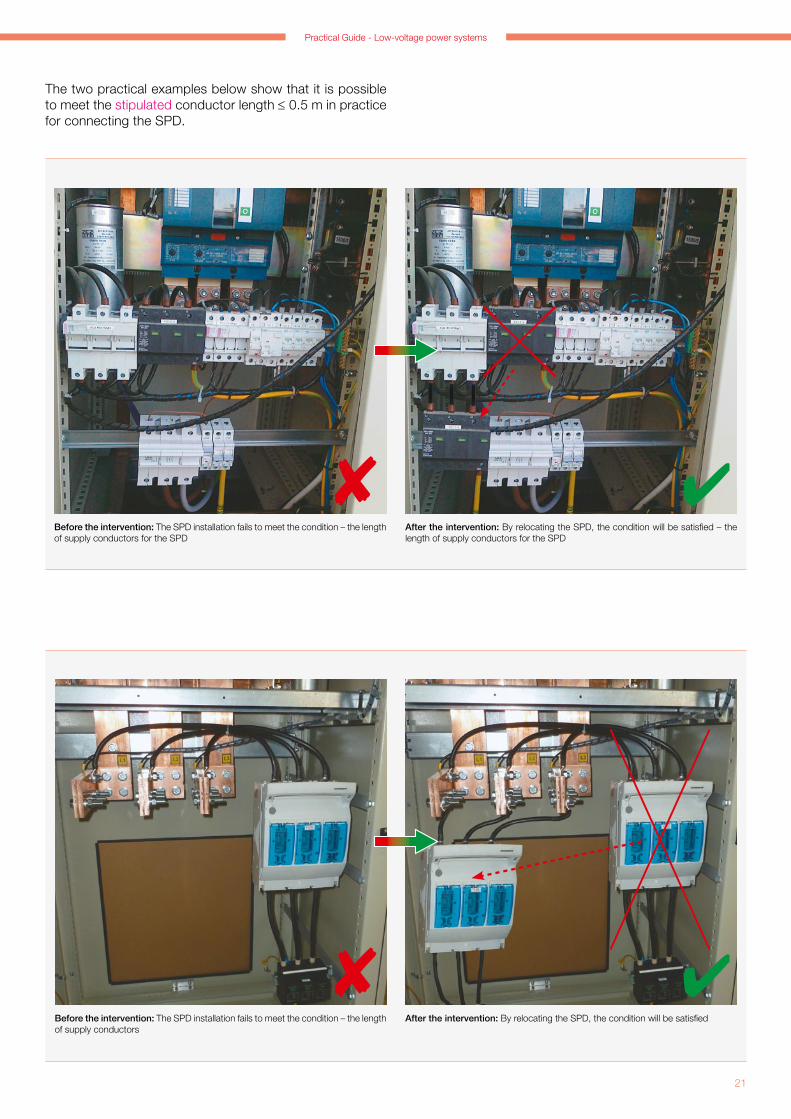
The two practical examples below show that it is possible to meet the stipulated conductor length ≤ 0.5 m in practice for connecting the SPD.
Before the intervention: The SPD installation fails to meet the condition – the length of supply conductors for the SPD
After the intervention: By relocating the SPD, the condition will be satisfied – the length of supply conductors for the SPD
Before the intervention: The SPD installation fails to meet the condition – the length of supply conductors
After the intervention: By relocating the SPD, the condition will be satisfied
22
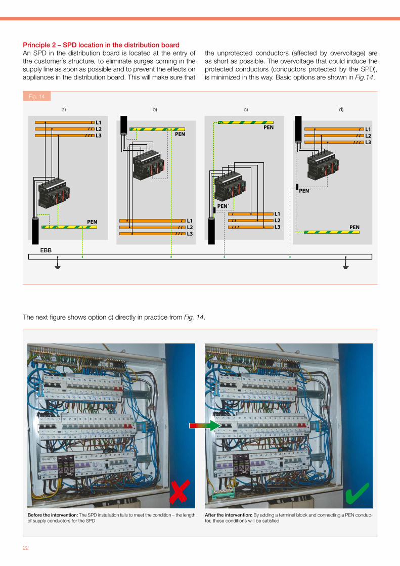
Principle 2 – SPD location in the distribution board An SPD in the distribution board is located at the entry of the customer´s structure, to eliminate surges coming in the supply line as soon as possible and to prevent the effects on appliances in the distribution board. This will make sure that
The next fi gure shows option c) directly in practice from Fig. 14.
the unprotected conductors (affected by overvoltage) are as short as possible. The overvoltage that could induce the protected conductors (conductors protected by the SPD), is minimized in this way. Basic options are shown in Fig.14.
EBB
a) b) c) d)
Before the intervention: The SPD installation fails to meet the condition – the length of supply conductors for the SPD
After the intervention: By adding a terminal block and connecting a PEN conduc-tor, these conditions will be satisfi ed
Fig. 14
Practical Guide - Low-voltage power systems
23
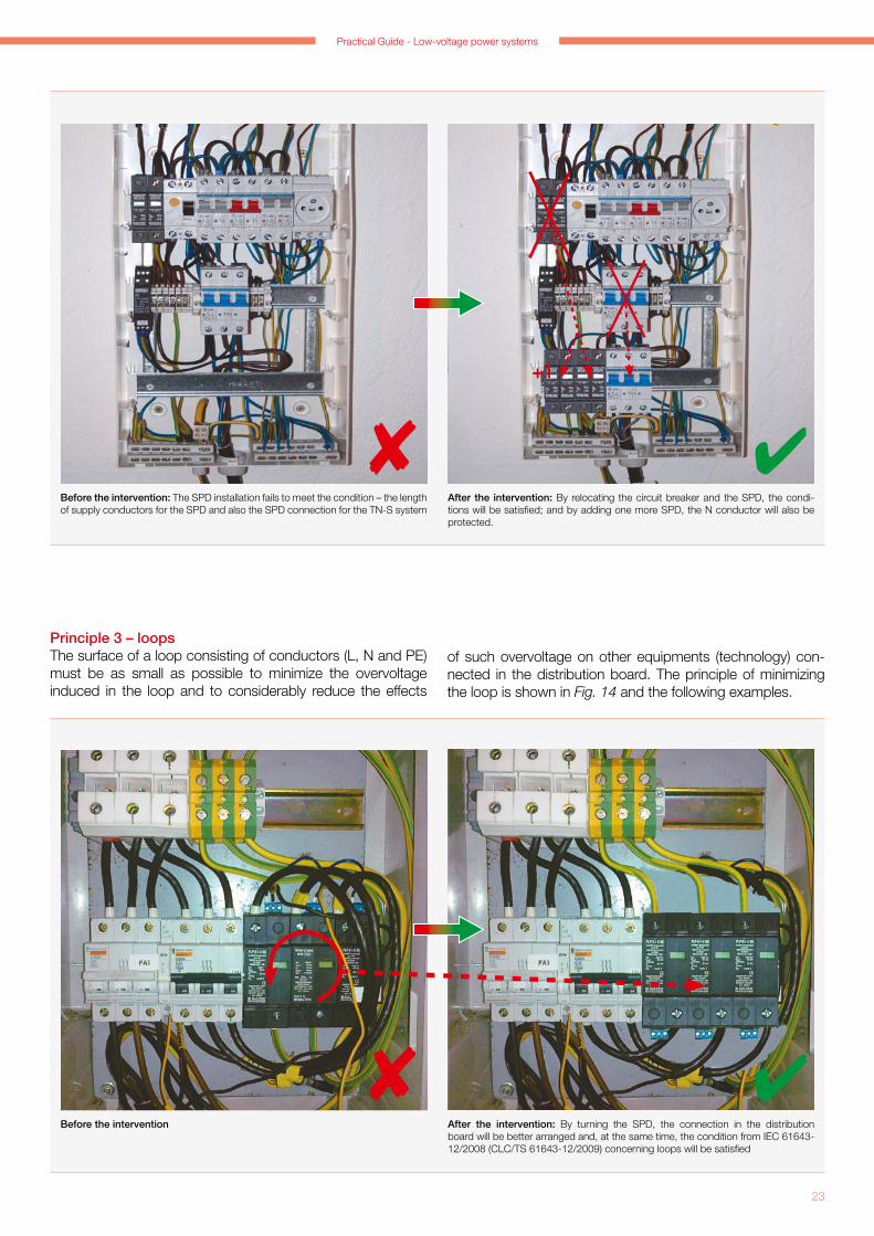
Principle 3 – loopsThe surface of a loop consisting of conductors (L, N and PE) must be as small as possible to minimize the overvoltage induced in the loop and to considerably reduce the effects
Before the intervention: The SPD installation fails to meet the condition – the length of supply conductors for the SPD and also the SPD connection for the TN-S system
Before the intervention After the intervention: By turning the SPD, the connection in the distribution board will be better arranged and, at the same time, the condition from IEC 61643-12/2008 (CLC/TS 61643-12/2009) concerning loops will be satisfi ed
After the intervention: By relocating the circuit breaker and the SPD, the condi-tions will be satisfi ed; and by adding one more SPD, the N conductor will also be protected.
of such overvoltage on other equipments (technology) con-nected in the distribution board. The principle of minimizing the loop is shown in Fig. 14 and the following examples.
+1

24
Principle 4 – conductor routing in the distribution boardWhen routing the conductors in the distribution board it is always necessary to separate protected („clean“) and un-protected („dirty“) conductors. To minimise the bonding be-tween the different types of conductors („clean“ and „dirty“), it is essential to keep the distance between them as great as possible (over 30 cm). If such a distance is impossible to
< 30 cm < 30 cm
Protected cable
Unprotected cable
Divider
Unprotected cable
Protected cable
90°
> 30 cm
Protected cable
Unprotected cable
observe, a protection partition should be placed between them, see Fig. 15. If you cannot avoid crossing of protected and unprotected conductors, the crossing should be made in the right angle to prevent induction of interference pulses in the protected conductors, as shown in Fig. 16.
Protected cable
Unprotected cable
Protected cable
Unprotected cable
Before the intervention After the intervention: By relocating the SPD, the connection in the distribution board will be better arranged, the condition concerning loops specifi ed in IEC 61643-12/2008 (CLC/TS 61643-12/2009) will be satisfi ed and, at the same time, the condition stipulating the length of supply conductors for the SPD will be met as well
Fig. 15
Fig. 16
Practical Guide - Low-voltage power systems
25
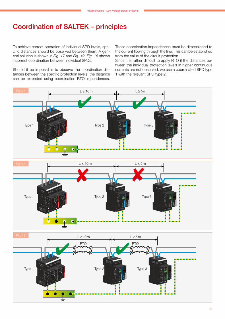
These coordination impendences must be dimensioned to the current fl owing through the line. This can be established from the value of the circuit protection.Since it is rather diffi cult to apply RTO if the distances be-tween the individual protection levels in higher continuous currents are not observed, we use a coordinated SPD type 1 with the relevant SPD type 2.
L ≥ 10 m L ≥ 5 m
Type 2Type 1 Type 3
RTO RTO
L < 10 m L < 5 m
Type 2Type 1 Type 3
L < 10 m L < 5 m
Type 2Type 1 Type 3
To achieve correct operation of individual SPD levels, spe-cifi c distances should be observed between them. A gen-eral solution is shown in Fig. 17 and Fig. 19. Fig. 18 shows incorrect coordination between individual SPDs.
Should it be impossible to observe the coordination dis-tances between the specifi c protection levels, the distance can be extended using coordination RTO impendences.
Coordination of SALTEK – principles
Fig. 18
Fig. 19
Fig. 17

26
0 m < L < 10 m L ≥ 5 m
FLP-SG50 V /1 SLP-275 V*
* according to type of connection
L ≥ 10 m L ≥ 5 m
L ≥ 5 m
FLP-B+C MAXI V* SLP-275 V*
* according to type of connection
L ≥ 10 m L ≥ 5 m
L ≥ 5 m
SLP-275 V*
* according to type of connection
SLP-275 V*
Type 2Type 2 Type 3
the distance between this SPD and the next one exceeds 10 m, an SPD type 2 should be located behind the SPD type 1+2, e.g., SLP-275 V (see Fig. 21).If the distance between this SPD and the next one is less than 10 m, you will not need to install an SPD type 2 behind the SPD type 1+2.The same applies onIy if an SPD type 2 is used instead of an SPD type 1+2 (see Fig. 22).
If the lightning arrester FLP-SG50 V/1 is used as an SPD type 1 and SLP-275 V is used as an SPD type 2, it will not be necessary to keep the distance between them over 10 m, because they are mutually coordinated and can be mounted next to each other (see Fig. 20).
If, for example, FLP-B++C MAXI V is installed as an SPD type 1, which is an SPD type 1+2 with Up < 1.5 kV and
Type 2Type 1 Type 3
Type 2Type 1 + 2 Type 3
FLP-SG50 V /1
Fig. 20
Fig. 21
Fig. 22

Practical Guide - Low-voltage power systems
27
Since there are situations in practice where the technology is connected directly from the main distribution board and the technology distribution board is usually at a distance of tens of meters, it is advisable to install an SPD in the tech-nology distribution board to cope with overvoltage as well as different earth potentials that might occur there, par-ticularly if the earthing (equipotential bonding) is not com-pletely all right. Consequently, an SPD type 1+2, featuring a diverting ability of In = 30 kA (8/20µs), should be installed in the position of the SPD type 2, whose diverting ability is In = 20 kA (8/20µs), to work In this case as a strong SPD type 2 (see Fig. 23-24 and Fig. 25-26).
Protective distance
To protect specifi c equipment, an SPD should be installed as close as possible to the protected equipment. If the SPD-SPD or SPD-technology distances are too great, the line features refl ections which can destroy the technology or the line insulation. These refl ections can even double the Up protection voltage level. The doubling effect occurs if the equipment is disconnected inside or its input imped-ance is high. If the distance between the SPD and the tech-nology is L ≤ 10 m, refl ections need not be taken into con-sideration. If the distance is great (L>> 10 m), remember to install an additional SPD (see Fig. 27-28 and Fig. 29-30).
FLP-B+C MAXI V/2 FLP-B+C MAXI V/2
Type 1+2
SLP-275 V/1+1
L >> 10 mL > 10 m
L > 10 m L > 5 m
Type 2
SLP-275 V/1+1 SLP-275 V/1+1 DA-275 V/1+1
L > 50 m
FLP-SG50 V /1
SLP-275 V/1+1
Type 1 Type 2
Type 2
L > 50 m
L > 100 m
FLP-SG50 V /1
FLP-12,5 V/1+1
FLP-B+C MAXI V/2
Type 1
Type 1
Type 1+2
Type 1+2
L > 100 m
FLP-SG50 V /1
SLP-275 V/1+1
FLP-SG50 V /1
Type 1
Type 1+2 Type 2
Type 2 Type 3
Fig. 23
Fig. 25
Fig. 27
Fig. 29
Fig. 24
Fig. 26
Fig. 28
Fig. 30
28
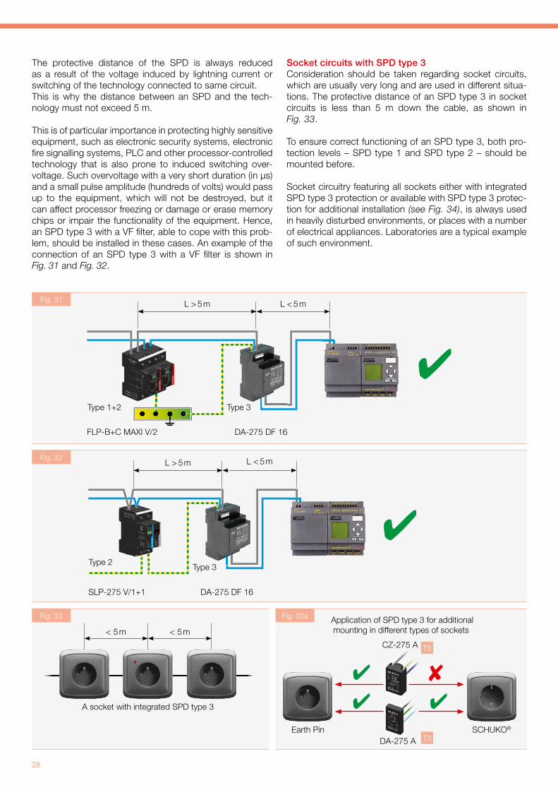
The protective distance of the SPD is always reduced as a result of the voltage induced by lightning current or switching of the technology connected to same circuit. This is why the distance between an SPD and the tech-nology must not exceed 5 m.
This is of particular importance in protecting highly sensitive equipment, such as electronic security systems, electronic fi re signalling systems, PLC and other processor-controlled technology that is also prone to induced switching over-voltage. Such overvoltage with a very short duration (in µs) and a small pulse amplitude (hundreds of volts) would pass up to the equipment, which will not be destroyed, but it can affect processor freezing or damage or erase memory chips or impair the functionality of the equipment. Hence, an SPD type 3 with a VF fi lter, able to cope with this prob-lem, should be installed in these cases. An example of the connection of an SPD type 3 with a VF fi lter is shown in Fig. 31 and Fig. 32.
SLP-275 V/1+1
Type 2 Type 3
DA-275 DF 16
L > 5 m L < 5 m
Socket circuits with SPD type 3Consideration should be taken regarding socket circuits, which are usually very long and are used in different situa-tions. The protective distance of an SPD type 3 in socket circuits is less than 5 m down the cable, as shown in Fig. 33.
To ensure correct functioning of an SPD type 3, both pro-tection levels – SPD type 1 and SPD type 2 – should be mounted before.
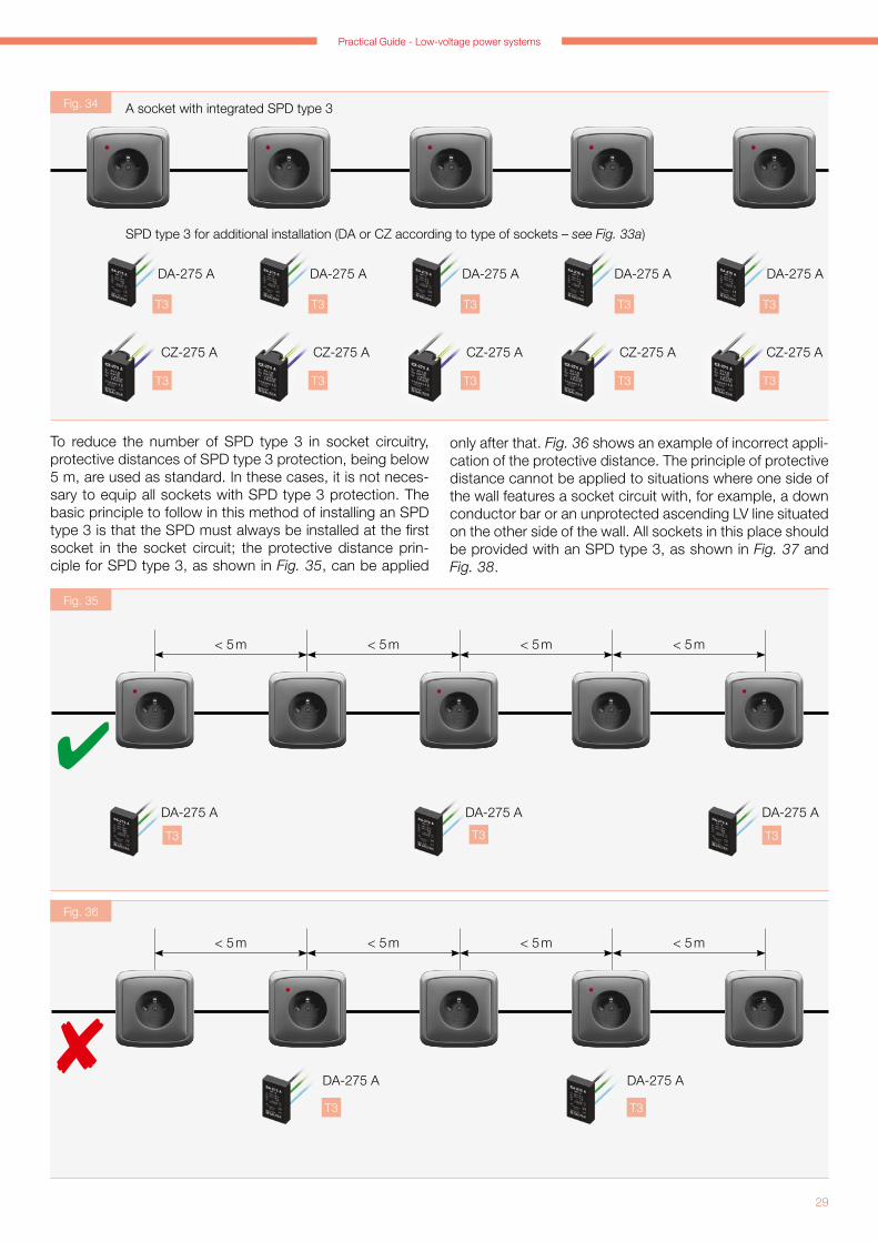
Socket circuitry featuring all sockets either with integrated SPD type 3 protection or available with SPD type 3 protec-tion for additional installation (see Fig. 34), is always used in heavily disturbed environments, or places with a number of electrical appliances. Laboratories are a typical example of such environment.
< 5 m < 5 m
A socket with integrated SPD type 3
Application of SPD type 3 for additional mounting in different types of sockets
T3
T3
FLP-B+C MAXI V/2
Type 3
DA-275 DF 16
L > 5 m L < 5 m
Type 1+2
DA-275 A
CZ-275 A
Fig. 31
Fig. 32
Fig. 33 Fig. 33a
Earth Pin SCHUKO®
Practical Guide - Low-voltage power systems
29
DA-275 A DA-275 A DA-275 A DA-275 A DA-275 A
CZ-275 A CZ-275 A CZ-275 A CZ-275 A CZ-275 A
T3T3T3T3T3
T3T3T3T3T3
DA-275 A DA-275 A DA-275 A
< 5 m < 5 m < 5 m < 5 m
T3T3T3
DA-275 A DA-275 A
< 5 m < 5 m < 5 m < 5 m
T3T3
To reduce the number of SPD type 3 in socket circuitry, protective distances of SPD type 3 protection, being below 5 m, are used as standard. In these cases, it is not neces-sary to equip all sockets with SPD type 3 protection. The basic principle to follow in this method of installing an SPD type 3 is that the SPD must always be installed at the fi rst socket in the socket circuit; the protective distance prin-ciple for SPD type 3, as shown in Fig. 35, can be applied
only after that. Fig. 36 shows an example of incorrect appli-cation of the protective distance. The principle of protective distance cannot be applied to situations where one side of the wall features a socket circuit with, for example, a down conductor bar or an unprotected ascending LV line situated on the other side of the wall. All sockets in this place should be provided with an SPD type 3, as shown in Fig. 37 and Fig. 38.
A socket with integrated SPD type 3
SPD type 3 for additional installation (DA or CZ according to type of sockets – see Fig. 33a)
Fig. 34
Fig. 35
Fig. 36
30
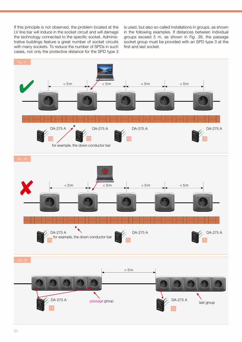
If this principle is not observed, the problem located at the LV line bar will induce in the socket circuit and will damage the technology connected to the specifi c socket. Adminis-trative buildings feature a great number of socket circuits with many sockets. To reduce the number of SPDs in such cases, not only the protective distance for the SPD type 3
is used, but also so-called installations in groups, as shown in the following examples. If distances between individual groups exceed 5 m, as shown in Fig. 39, the passage socket group must be provided with an SPD type 3 at the fi rst and last socket.
DA-275 A DA-275 ADA-275 A DA-275 A
< 5 m < 5 m < 5 m < 5 m
for example, the down conductor bar
T3T3T3T3
DA-275 A DA-275 A DA-275 A
< 5 m < 5 m < 5 m < 5 m
for example, the down conductor barT3T3T3
passage group last groupT3
> 5 m
DA-275 A DA-275 A
T3
Fig. 37
Fig. 38
Fig. 39

Practical Guide - Low-voltage power systems
31
be provided with an SPD type 3. This option is shown in Fig. 41.
SPD connection considering Up (protective voltage level)
Connection of SPDs in sequence is shown in the following fi gures (Fig. 42-43 and Fig. 44-45).
passage group last group
T3
< 5 m
DA-275 A DA-275 A
passage group last group
for example, the down conductor bar
< 5 m
DA-275 A DA-275 A
Type 1+2Up (L-N) ≤ 1.5 kV
Type 2Up (L-N) ≤ 1.2 kV
Type 3
Up (L-N) ≤ 1.0 kV
Type 3
Up (L-N) ≤ 1.0 kV
Fig. 44
Type 1
Up (L-N) ≤ 2.5 kV
Type 1
Up (L-N) ≤ 2.5 kV
Type 3
Up (L-N) ≤ 1.0 kV
Type 2
Up (L-N) ≤ 1.2 kV
T3
T3T3
If the group is not a passage group, an SPD type 3 should always be installed at the fi rst socket. Should the distance between individual socket groups be less than 5 m, you can use the property of the SPD protective distance, i.e., you do not need to install an SPD type 3 at the last socket in the passage group, as shown in Fig. 40. The principle of protective distance cannot be applied in situations where the distance between two groups is less than 5 m, and, for example, a down conductor bar or an unprotected LV line is located on the other side of the wall. It is neces-sary in this case that the last socket of the passage group
Fig. 40
Fig. 41
Fig. 42 Fig. 43
Fig. 44 Fig. 45

32
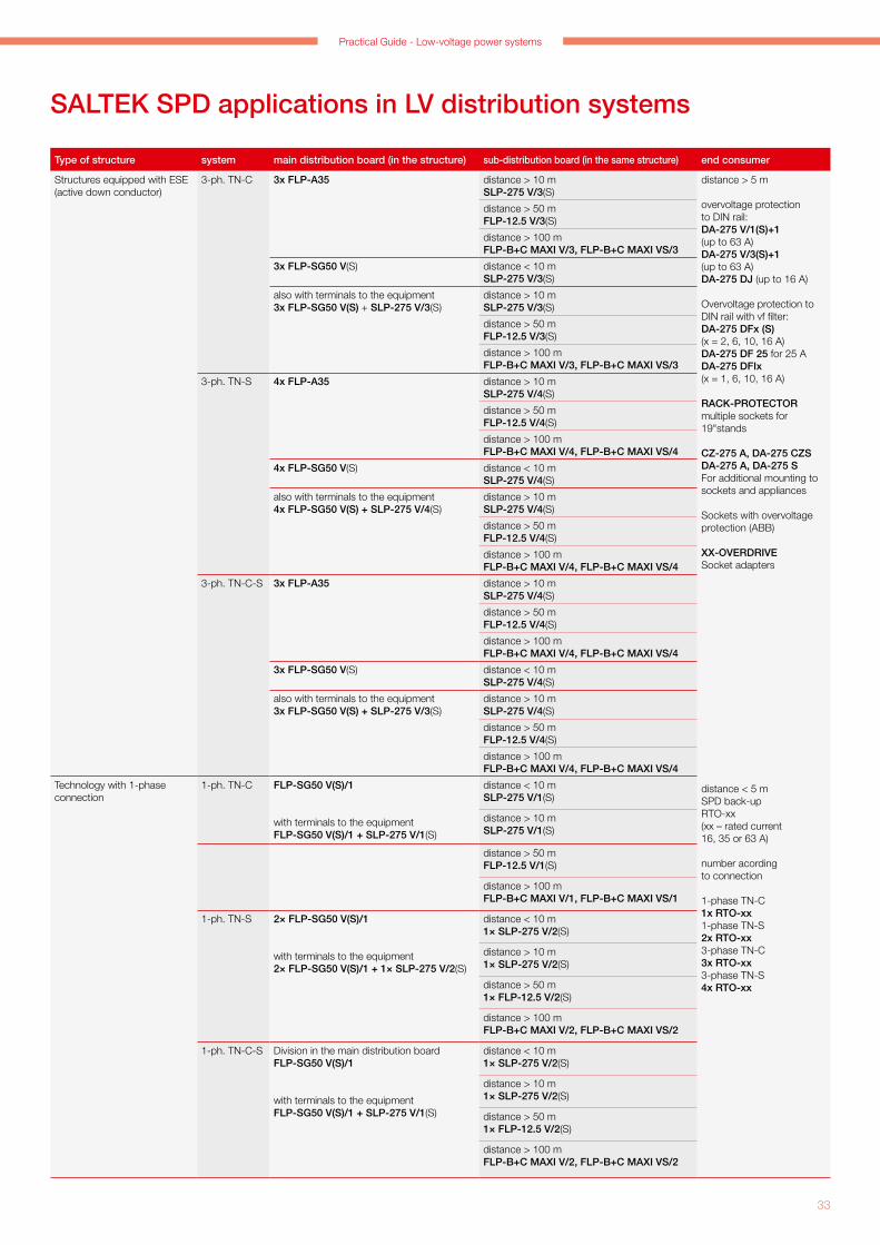
SALTEK SPD applications in LV distribution systems
Type of structure system main distribution board (in the structure) sub-distribution board (in the same structure) end consumer
Family houses, administrative buildings, technologic units, industrial structures
3-ph. TN-C FLP-B+C MAXI VS/3, FLP-B+C MAXI V/3FLP-25-T1-VS/3, FLP-25-T1-V/3
distance > 10 mSLP-275 V/3(S)
distance > 5 m
overvoltage protection to DIN rail:DA-275 V/1(S)+1 (to 63 A)DA-275 V/3(S)+1 (to 63 A)DA-275 DJ (to 16 A)
overvoltage protection to a DIN rail with a vf filter:DA-275 DFx (S)(x = 2, 6, 10, 16 A)DA-275 DF 25 for 25 ADA-275 DFIx (x = 1, 6, 10, 16 A)
RACK-PROTECTORmultiple sockets to 19"stands
CZ-275 A, DA-275 CZSDA-275 A, DA-275 S for additional assembly to the sockets and appliances
sockets with overvoltage protection (ABB)
XX-OVERDRIVEsocket adapters
distance < 5 mplace before the overvoltage protectionRTO-xx (xx – rated current 16, 35 or 63 A)
number acording to connection
1-phase TN-C1x RTO-xx1-phase TN-S2x RTO-xx3-phase TN-C3x RTO-xx3-phase TN-S4x RTO-xx
distance > 50 mFLP-12.5 V/3(S)
distance > 100 mFLP-B+C MAXI V/3, FLP-B+C MAXI VS/3
FLP-25-T1-VS/3, FLP-25-T1-V/3 distance < 10 mSLP-275 V/3(S)
FLP-B+C MAXI VS/3, FLP-B+C MAXI V/3FLP-25-T1-VS/3 + SLP-275 V/3 SFLP-25-T1-V/3 + SLP-275 V/3(also with terminals to the equipment)
distance > 10 mSLP-275 V/3(S)
distance > 50 mFLP-12.5 V/3(S)
distance > 100 mFLP-B+C MAXI V/3, FLP-B+C MAXI VS/3
3-ph. TN-S FLP-B+C MAXI VS/4, FLP-B+C MAXI V/4FLP-25-T1-VS/4, FLP-25-T1-V/4
distance > 10 mSLP-275 V/4(S)
distance > 50 mFLP-12.5 V/4(S)
distance > 100 mFLP-B+C MAXI V/4, FLP-B+C MAXI VS/4
FLP-25-T1-VS/4, FLP-25-T1-V/4 distance < 10 mSLP-275 V/4(S)
FLP-B+C MAXI VS/4, FLP-B+C MAXI V/4FLP-25-T1-VS/4 + SLP-275 V/4 SFLP-25-T1-V/4 + SLP-275 V/4(also with terminals to the equipment)
distance > 10 mSLP-275 V/4(S)
distance > 50 mFLP-12.5 V/4(S)
distance > 100 mFLP-B+C MAXI V/4, FLP-B+C MAXI VS/4
3-ph. TN-C-S
FLP-B+C MAXI VS/3, FLP-B+C MAXI V/3FLP-25-T1-VS/3, FLP-25-T1-V/3
distance > 10 mSLP-275 V/4(S)
distance > 50 mFLP-12.5 V/4(S)
distance > 100 mFLP-B+C MAXI V/4, FLP-B+C MAXI VS/4
FLP-25-T1-VS/3, FLP-25-T1-V/3 distance < 10 mSLP-275 V/4(S)
FLP-B+C MAXI VS/3, FLP-B+C MAXI V/3FLP-25-T1-VS/3 + SLP-275 V/3 SFLP-25-T1-V/3 + SLP-275 V/3(also with terminals to the equipment)
distance > 10 mSLP-275 V/4(S)
distance > 50 mFLP-12.5 V/4(S)
distance > 100 mFLP-B+C MAXI V/4, FLP-B+C MAXI VS/4
Blocks of flats with 12 or more apartments (SPD located in the apart. distr. boards)
3-ph. TN-C FLP-12.5 V/3(S)
3-ph. TN-S FLP-12.5 V/4(S)
3-ph. TN-C-S
division in the apartment distr. board FLP-12.5 V/3(S)
1-ph. TN-C FLP-B+C MAXI V/1, FLP-B+C MAXI VS/1
1-ph. TN-S FLP-12.5 V/2(S)
Demanding applications (structures – operations classified at the risk of explosion, chemical plants…, structures of a very high importance)
3-ph. TN-C 3× FLP-SG50 V(S)
with terminals to the equipment3× FLP-SG50 V(S) + 1× SLP-275 V/3(S)
distance < 10 m1× SLP-275 V/3(S)distance > 10 mSLP-275 V/3(S)distance > 50 mFLP-12.5 V/3(S)distance > 100 mFLP-B+C MAXI V/3, FLP-B+C MAXI VS/3
3-ph. TN-S 4× FLP-SG50 V(S)
with terminals to the equipment4× FLP-SG50 V(S) + 1× SLP-275 V/4(S)
distance < 10 m1× SLP-275 V/4(S)distance > 10 mSLP-275 V/4(S)distance > 50 mFLP-12.5 V/4(S)distance > 100 mFLP-B+C MAXI V/4, FLP-B+C MAXI VS/4
3-ph. TN-C-S
division in the main distribution board3× FLP-SG50 V(S)
with terminals to the equipment3× FLP-SG50 V(S) + 1× SLP-275 V/4(S)
distance < 10 m1× SLP-275 V/4(S)distance > 10 mSLP-275 V/4(S)distance > 50 mFLP-12.5 V/4(S)distance > 100 mFLP-B+C MAXI V/4, FLP-B+C MAXI VS/4
Practical Guide - Low-voltage power systems
33
SALTEK SPD applications in LV distribution systems
Type of structure system main distribution board (in the structure) sub-distribution board (in the same structure) end consumer
Structures equipped with ESE (active down conductor)
3-ph. TN-C 3x FLP-A35 distance > 10 mSLP-275 V/3(S)
distance > 5 m
overvoltage protection to DIN rail:DA-275 V/1(S)+1 (up to 63 A)DA-275 V/3(S)+1 (up to 63 A)DA-275 DJ (up to 16 A)
Overvoltage protection to DIN rail with vf filter:DA-275 DFx (S)(x = 2, 6, 10, 16 A)DA-275 DF 25 for 25 ADA-275 DFIx(x = 1, 6, 10, 16 A)
RACK-PROTECTORmultiple sockets for 19"stands
CZ-275 A, DA-275 CZSDA-275 A, DA-275 S For additional mounting to sockets and appliances
Sockets with overvoltage protection (ABB)
XX-OVERDRIVESocket adapters
distance < 5 mSPD back-upRTO-xx (xx – rated current 16, 35 or 63 A)
number acording to connection
1-phase TN-C1x RTO-xx1-phase TN-S2x RTO-xx3-phase TN-C3x RTO-xx3-phase TN-S4x RTO-xx
distance > 50 mFLP-12.5 V/3(S)
distance > 100 mFLP-B+C MAXI V/3, FLP-B+C MAXI VS/3
3x FLP-SG50 V(S) distance < 10 mSLP-275 V/3(S)
also with terminals to the equipment3x FLP-SG50 V(S) + SLP-275 V/3(S)
distance > 10 mSLP-275 V/3(S)
distance > 50 mFLP-12.5 V/3(S)
distance > 100 mFLP-B+C MAXI V/3, FLP-B+C MAXI VS/3
3-ph. TN-S 4x FLP-A35 distance > 10 mSLP-275 V/4(S)
distance > 50 mFLP-12.5 V/4(S)
distance > 100 mFLP-B+C MAXI V/4, FLP-B+C MAXI VS/4
4x FLP-SG50 V(S) distance < 10 mSLP-275 V/4(S)
also with terminals to the equipment4x FLP-SG50 V(S) + SLP-275 V/4(S)
distance > 10 mSLP-275 V/4(S)
distance > 50 mFLP-12.5 V/4(S)
distance > 100 mFLP-B+C MAXI V/4, FLP-B+C MAXI VS/4
3-ph. TN-C-S 3x FLP-A35 distance > 10 mSLP-275 V/4(S)
distance > 50 mFLP-12.5 V/4(S)
distance > 100 mFLP-B+C MAXI V/4, FLP-B+C MAXI VS/4
3x FLP-SG50 V(S) distance < 10 mSLP-275 V/4(S)
also with terminals to the equipment3x FLP-SG50 V(S) + SLP-275 V/3(S)
distance > 10 mSLP-275 V/4(S)
distance > 50 mFLP-12.5 V/4(S)
distance > 100 mFLP-B+C MAXI V/4, FLP-B+C MAXI VS/4
Technology with 1-phase connection
1-ph. TN-C FLP-SG50 V(S)/1
with terminals to the equipmentFLP-SG50 V(S)/1 + SLP-275 V/1(S)
distance < 10 mSLP-275 V/1(S)
distance > 10 mSLP-275 V/1(S)
distance > 50 mFLP-12.5 V/1(S)
distance > 100 mFLP-B+C MAXI V/1, FLP-B+C MAXI VS/1
1-ph. TN-S 2× FLP-SG50 V(S)/1
with terminals to the equipment2× FLP-SG50 V(S)/1 + 1× SLP-275 V/2(S)
distance < 10 m1× SLP-275 V/2(S)
distance > 10 m1× SLP-275 V/2(S)
distance > 50 m1× FLP-12.5 V/2(S)
distance > 100 mFLP-B+C MAXI V/2, FLP-B+C MAXI VS/2
1-ph. TN-C-S Division in the main distribution boardFLP-SG50 V(S)/1
with terminals to the equipmentFLP-SG50 V(S)/1 + SLP-275 V/1(S)
distance < 10 m1× SLP-275 V/2(S)
distance > 10 m1× SLP-275 V/2(S)
distance > 50 m1× FLP-12.5 V/2(S)
distance > 100 mFLP-B+C MAXI V/2, FLP-B+C MAXI VS/2
34
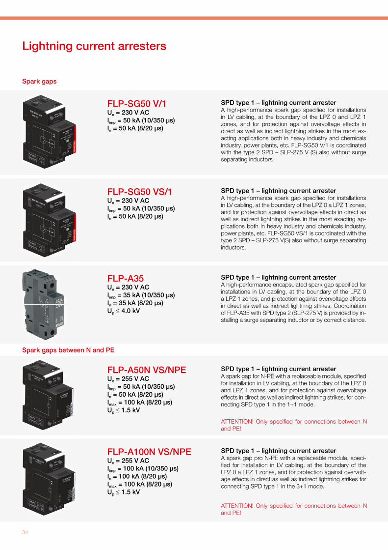
Lightning current arresters
Spark gaps
FLP-A35Un = 230 V ACIimp = 35 kA (10/350 µs)In = 35 kA (8/20 µs) Up ≤ 4.0 kV
SPD type 1 – lightning current arresterA high-performance encapsulated spark gap specifi ed for installations in LV cabling, at the boundary of the LPZ 0 a LPZ 1 zones, and protection against overvoltage effects in direct as well as indirect lightning strikes. Coordination of FLP-A35 with SPD type 2 (SLP-275 V) is provided by in-stalling a surge separating inductor or by correct distance.
FLP-SG50 VS/1Un = 230 V ACIimp = 50 kA (10/350 µs)In = 50 kA (8/20 µs)
SPD type 1 – lightning current arrester A high-performance spark gap specifi ed for installationsin LV cabling, at the boundary of the LPZ 0 a LPZ 1 zones, and for protection against overvoltage effects in direct as well as indirect lightning strikes in the most exacting ap-plications both in heavy industry and chemicals industry, power plants, etc. FLP-SG50 VS/1 is coordinated with the type 2 SPD – SLP-275 V(S) also without surge separating inductors.
FLP-SG50 V/1Un = 230 V ACIimp = 50 kA (10/350 µs)In = 50 kA (8/20 µs)
SPD type 1 – lightning current arrester A high-performance spark gap specifi ed for installationsin LV cabling, at the boundary of the LPZ 0 and LPZ 1 zones, and for protection against overvoltage effects in direct as well as indirect lightning strikes in the most ex-acting applications both in heavy industry and chemicals industry, power plants, etc. FLP-SG50 V/1 is coordinated with the type 2 SPD – SLP-275 V (S) also without surge separating inductors.
FLP-A50N VS/NPEUc = 255 V ACIimp = 50 kA (10/350 µs)In = 50 kA (8/20 µs)Imax = 100 kA (8/20 µs) Up ≤ 1.5 kV
SPD type 1 – lightning current arrester A spark gap for N-PE with a replaceable module, specifi ed for installation in LV cabling, at the boundary of the LPZ 0 and LPZ 1 zones, and for protection against overvoltage effects in direct as well as indirect lightning strikes, for con-necting SPD type 1 in the 1+1 mode.
ATTENTION! Only specifi ed for connections between N and PE!
FLP-A100N VS/NPEUc = 255 V ACIimp = 100 kA (10/350 µs)In = 100 kA (8/20 µs)Imax = 100 kA (8/20 µs) Up ≤ 1.5 kV
SPD type 1 – lightning current arrester A spark gap pro N-PE with a replaceable module, speci-fi ed for installation in LV cabling, at the boundary of the LPZ 0 a LPZ 1 zones, and for protection against overvolt-age effects in direct as well as indirect lightning strikes for connecting SPD type 1 in the 3+1 mode.
Spark gaps between N and PE
ATTENTION! Only specifi ed for connections between N and PE!
Spark gaps between N and PE

Practical Guide - Low-voltage power systems
35
Lightning current arresters
Combined lightning current arresters SPD type 1
FLP-25-T1-V/4Un = 230 V ACIimp = 25 kA (10/350 µs)Up ≤ 1.5 kV
Zero leakage current No follow-on current
FLP-25-T1-VS/3Un = 230 V ACIimp = 25 kA (10/350 µs)Up ≤ 1.5 kV
Zero leakage current No follow-on currentStatus remote signalling
FLP-25-T1-VS/4Un = 230 V ACIimp = 25 kA (10/350 µs)Up ≤ 1.5 kV
Zero leakage current No follow-on currentStatus remote signalling
FLP-25-T1-V/3+1Un = 230 V ACIimp = 25 kA (10/350 µs)Up ≤ 1.5 kVUp ≤ 2.2 kV (L-PE)
Zero leakage current No follow-on current
FLP-25-T1-VS/3+1Un = 230 V ACIimp = 25 kA (10/350 µs)Up ≤ 1.5 kVUp ≤ 2.2 kV (L-PE)
Zero leakage current No follow-on currentStatus remote signalling
SPD type 1 – lightning current arrester A combination of a three-pole high-performance lightning arrester and encapsulated effi ciency spark gap, connected in the 3+1 mode for installations in LV cabling at the boundary of the LPZ 0 – LPZ 1 zones and higher levels. It is used to protect against overvoltage effects in direct as well as indirect lightning strikes. It can be used in a variety of installations, suitable for family houses, administrative and commercial buildings, or in subsidiary distribution boards of large premises. It is specifi ed for three-phase TT networks.
FLP-25-T1-V/3Un = 230 V ACIimp = 25 kA (10/350 µs)Up ≤ 1.5 kV
Zero leakage current No follow-on current
SPD type 1 – lightning current arrester A three-pole high-performance lightning current arrester for in-stallation in LV cabling at the boundary of the LPZ 0A – LPZ 1 zones and higher levels. It is used to protect against overvoltage effects in direct as well as indirect lightning strikes. It can be used in a variety of installations, suitable for family houses, administra-tive and commercial buildings, or in sub-distribution boards of large premises. It is specifi ed for three-phase TN-C networks.
SPD type 1 – lightning current arrester A combination of a three-pole high-performance lightning arrester and encapsulated effi ciency spark gap, connected in the 3+1 mode for installations in LV cabling at the boundary of the LPZ 0 – LPZ 1 zones and higher levels. It is used to protect against overvoltage effects in direct as well as indirect lightning strikes. It can be used in a variety of installations, suitable for family houses, administrative and commercial buildings, or in sub-distribution boards of large premises. It is specifi ed for three-phase TT networks.
SPD type 1 – lightning current arrester A four-pole high-performance lightning current arrester for instal-lations in LV cabling at the boundary of the LPZ 0A – LPZ 1 zones and higher levels. It is used to protect against overvoltage effects in direct as well as indirect lightning strikes. It can be used in a variety of installations, suitable for family houses, administrative and commercial buildings, or in sub-distribution boards of large premises. It is specifi ed for three-phase TN-S networks.
SPD type 1 – lightning current arrester A four-pole high-performance lightning current arrester for instal-lations in LV cabling at the boundary of the LPZ 0A – LPZ 1 zones and higher levels. It is used to protect against overvoltage effects in direct as well as indirect lightning strikes. It can be used in a variety of installations, suitable for family houses, administrative and commercial buildings, or in sub-distribution boards of large premises. It is specifi ed for three-phase TN-S networks.
SPD type 1 – lightning current arrester A three-pole high-performance lightning current arrester for in-stallations in LV cabling at the boundary of the LPZ 0A – LPZ 1 zones and higher levels. It is used to protect against overvoltage effects in direct as well as indirect lightning strikes. It can be used in a variety of installations, suitable for family houses, administra-tive and commercial buildings, or in sub-distribution boards of large premises. It is specifi ed for three-phase TN-C networks.

36
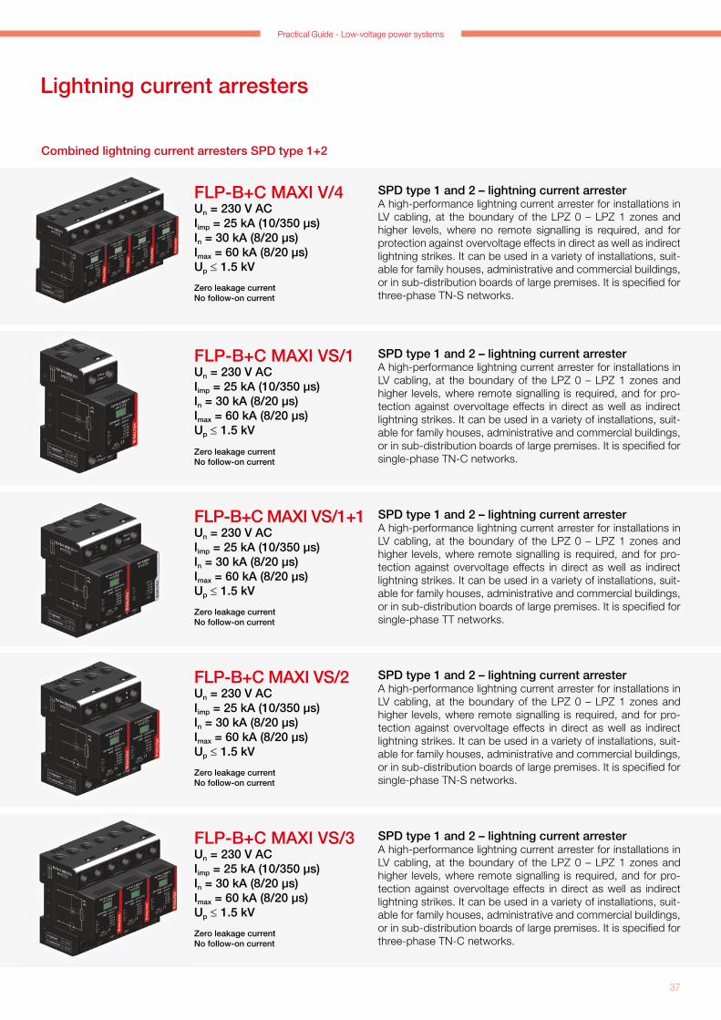
Lightning current arresters
Combined lightning current arresters SPD type 1+2
FLP-B+C MAXI V/2Un = 230 V ACIimp = 25 kA (10/350 µs)In = 30 kA (8/20 µs)Imax = 60 kA (8/20 µs)Up ≤ 1.5 kV
Zero leakage current No follow-on current
SPD type 1 and 2 – lightning current arrester A high-performance lightning current arrester for installations in LV cabling, at the boundary of the LPZ 0 – LPZ 1 zones and higher levels, where no remote signalling is required, and for protection against overvoltage effects in direct as well as indirect lightning strikes. It can be used in a variety of installations, suit-able for family houses, administrative and commercial buildings, or in sub-distribution boards of large premises. It is specifi ed for single-phase TN-S networks.
FLP-B+C MAXI V/1+1Un = 230 V ACIimp = 25 kA (10/350 µs)In = 30 kA (8/20 µs)Imax = 60 kA (8/20 µs)Up ≤ 1.5 kV
Zero leakage current No follow-on current
SPD type 1 and 2 – lightning current arrester A high-performance lightning current arrester for installations in LV cabling, at the boundary of the LPZ 0 – LPZ 1 zones and higher levels, where no remote signalling is required, and for protection against overvoltage effects in direct as well as indirect lightning strikes. It can be used in a variety of installations, suit-able for family houses, administrative and commercial buildings, or in subsidiary distribution boards of large premises. It is speci-fi ed for single-phase TT networks.
FLP-B+C MAXI V/3Un = 230 V ACIimp = 25 kA (10/350 µs)In = 30 kA (8/20 µs)Imax = 60 kA (8/20 µs)Up ≤ 1.5 kV
Zero leakage current No follow-on current
SPD type 1 and 2 – lightning current arrester A high-performance lightning current arrester for installations in LV cabling, at the boundary of the LPZ 0 – LPZ 1 zones and higher levels, where no remote signalling is required, and for protection against overvoltage effects in direct as well as indirect lightning strikes. It can be used in a variety of installations, suit-able for family houses, administrative and commercial buildings, or in sub-distribution boards of large premises. It is specifi ed for three-phase TN-C networks.
FLP-B+C MAXI V/3+1Un = 230 V ACIimp = 25 kA (10/350 µs)In = 30 kA (8/20 µs)Imax = 60 kA (8/20 µs)Up ≤ 1.5 kV
Zero leakage current No follow-on current
SPD type 1 and 2 – lightning current arrester A high-performance lightning current arrester for installations in LV cabling, at the boundary of the LPZ 0 – LPZ 1 zones and higher levels, where no remote signalling is required, and for protection against overvoltage effects in direct as well as indirect lightning strikes. It can be used in a variety of installations, suit-able for family houses, administrative and commercial buildings, or in sub-distribution boards of large premises. It is specifi ed for three-phase TT networks.
SPD type 1 and 2 – lightning current arrester A high-performance lightning current arrester for installations in LV cabling, at the boundary of the LPZ 0 – LPZ 1 zones and higher levels, where no remote signalling is required, and for protection against overvoltage effects in direct as well as indirect lightning strikes. It can be used in a variety of installations, suit-able for family houses, administrative and commercial buildings, or in sub-distribution boards of large premises. It is specifi ed for single-phase TN-C networks.
FLP-B+C MAXI V/1Un = 230 V ACIimp = 25 kA (10/350 µs)In = 30 kA (8/20 µs)Imax = 60 kA (8/20 µs)Up ≤ 1.5 kV
Zero leakage current No follow-on current
FLP-B+C MAXI V/3+1UIIIU
Zero leakage current No follow-on current
Practical Guide - Low-voltage power systems
37
Lightning current arresters
Combined lightning current arresters SPD type 1+2
FLP-B+C MAXI VS/1+1Un = 230 V ACIimp = 25 kA (10/350 µs)In = 30 kA (8/20 µs)Imax = 60 kA (8/20 µs)Up ≤ 1.5 kV
Zero leakage current No follow-on current
SPD type 1 and 2 – lightning current arrester A high-performance lightning current arrester for installations in LV cabling, at the boundary of the LPZ 0 – LPZ 1 zones and higher levels, where remote signalling is required, and for pro-tection against overvoltage effects in direct as well as indirect lightning strikes. It can be used in a variety of installations, suit-able for family houses, administrative and commercial buildings, or in sub-distribution boards of large premises. It is specifi ed for single-phase TT networks.
FLP-B+C MAXI VS/1Un = 230 V ACIimp = 25 kA (10/350 µs)In = 30 kA (8/20 µs)Imax = 60 kA (8/20 µs)Up ≤ 1.5 kV
Zero leakage current No follow-on current
SPD type 1 and 2 – lightning current arrester A high-performance lightning current arrester for installations in LV cabling, at the boundary of the LPZ 0 – LPZ 1 zones and higher levels, where remote signalling is required, and for pro-tection against overvoltage effects in direct as well as indirect lightning strikes. It can be used in a variety of installations, suit-able for family houses, administrative and commercial buildings, or in sub-distribution boards of large premises. It is specifi ed for single-phase TN-C networks.
FLP-B+C MAXI VS/2Un = 230 V ACIimp = 25 kA (10/350 µs)In = 30 kA (8/20 µs)Imax = 60 kA (8/20 µs)Up ≤ 1.5 kV
Zero leakage currentNo follow-on current
SPD type 1 and 2 – lightning current arrester A high-performance lightning current arrester for installations in LV cabling, at the boundary of the LPZ 0 – LPZ 1 zones and higher levels, where remote signalling is required, and for pro-tection against overvoltage effects in direct as well as indirect lightning strikes. It can be used in a variety of installations, suit-able for family houses, administrative and commercial buildings, or in sub-distribution boards of large premises. It is specifi ed for single-phase TN-S networks.
FLP-B+C MAXI VS/3Un = 230 V ACIimp = 25 kA (10/350 µs)In = 30 kA (8/20 µs)Imax = 60 kA (8/20 µs)Up ≤ 1.5 kV
Zero leakage current No follow-on current
SPD type 1 and 2 – lightning current arrester A high-performance lightning current arrester for installations in LV cabling, at the boundary of the LPZ 0 – LPZ 1 zones and higher levels, where remote signalling is required, and for pro-tection against overvoltage effects in direct as well as indirect lightning strikes. It can be used in a variety of installations, suit-able for family houses, administrative and commercial buildings, or in sub-distribution boards of large premises. It is specifi ed for three-phase TN-C networks.
SPD type 1 and 2 – lightning current arrester A high-performance lightning current arrester for installations in LV cabling, at the boundary of the LPZ 0 – LPZ 1 zones and higher levels, where no remote signalling is required, and for protection against overvoltage effects in direct as well as indirect lightning strikes. It can be used in a variety of installations, suit-able for family houses, administrative and commercial buildings, or in sub-distribution boards of large premises. It is specifi ed for three-phase TN-S networks.
FLP-B+C MAXI V/4Un = 230 V ACIimp = 25 kA (10/350 µs)In = 30 kA (8/20 µs)Imax = 60 kA (8/20 µs)Up ≤ 1.5 kV
Zero leakage current No follow-on current

38
Lightning current arresters
Combined lightning current arresters SPD type 1+2
FLP-12,5 V/1(S)Un = 230 V ACIimp = 12.5 kA (10/350 µs)In = 30 kA (8/20 µs) Imax = 60 kA (8/20 µs) Up ≤ 1.2 kV
Optional remote signalling (S)
FLP-B+C MAXI VS/4Un = 230 V ACIimp = 50 kA (10/350 µs)In = 50 kA (8/20 µs)Imax = 100 kA (8/20 µs) Up ≤ 1.5 kV
Zero leakage current No follow-on current
FLP-B+C MAXI VS/3+1Un = 230 V ACIimp = 50 kA (10/350 µs)In = 50 kA (8/20 µs)Imax = 100 kA (8/20 µs) Up ≤ 1.5 kV
Zero leakage current No follow-on current
SPD type 1 and 2 – lightning current arrester A high-performance lightning current arrester for installations in LV cabling, at the boundary of the LPZ 0 – LPZ 1 zones and higher levels, where remote signalling is required, and for pro-tection against overvoltage effects in direct as well as indirect lightning strikes. It can be used in a variety of installations, suit-able for family houses, administrative and commercial buildings, or in sub-distribution boards of large premises. It is specifi ed for three-phase TT networks.
FLP-12,5 V/1(S)+1Un = 230 V ACIimp = 12.5 kA (10/350 µs)In = 30 kA (8/20 µs) Imax = 60 kA (8/20 µs) Up ≤ 1.2 kV
Optional remote signalling (S)
SPD type 1 and 2 – lightning current arrester A varistor lightning current arrester specifi ed for installations in LV cabling at the boundary of the LPZ 0 – LPZ 1 zones and higher levels. It is used to protect against the effects of partial lightning strike currents, induced overvoltage in lightning strikes and against switching overvoltage. It is suitable for III and IV risk class buildings, in subsidiary distribution boards of large premises or the protection of air conditioners or heating cables. It is specifi ed for single-phase TT networks.
SPD type 1 and 2 – lightning current arrester A varistor lightning current arrester specifi ed for installations in LV cabling at the boundary of the LPZ 0 – LPZ 1 zones and higher levels. It is used to protect against the effects of partial lightning strike currents, induced overvoltage in lightning strikes and against switching overvoltage. It is suitable for III and IV risk class buildings, in sub-distribution boards of large premises or the protection of air conditioners or heating cables. It is specifi ed for single-phase TN-S networks.
SPD type 1 and 2 – lightning current arrester A high-performance lightning current arrester for installations in LV cabling, at the boundary of the LPZ 0 – LPZ 1 zones and higher levels, where remote signalling is required, and for pro-tection against overvoltage effects in direct as well as indirect lightning strikes. It can be used in a variety of installations, suit-able for family houses, administrative and commercial buildings, or in sub-distribution boards of large premises. It is specifi ed for three-phase TN-S networks.
FLP-12,5 V/2(S)Un = 230 V ACIimp = 12.5 kA (10/350 µs)In = 30 kA (8/20 µs) Imax = 60 kA (8/20 µs) Up ≤ 1.2 kV
Optional remote signalling (S)
Varistor lightning arresters SPD type 1+2
SPD type 1 and 2 – lightning current arrester A varistor lightning current arrester specifi ed for installations in LV cabling at the boundary of the LPZ 0 – LPZ 1 zones and higher levels. It is used to protect against the effects of partial lightning strike currents, induced overvoltage in lightning strikes and against switching overvoltage. It is suitable for III and IV risk class buildings, in sub-distribution boards of large premises or the protection of air conditioners or heating cables. It is specifi ed for single-phase TN-C networks.
Varistor lightning arresters SPD type 1+2

Practical Guide - Low-voltage power systems
39
Lightning current arresters
Varistor lightning current arresters SPD type 1+2
Coordination impedance
FLP-12,5 V/4(S)Un = 230 V ACIimp = 12.5 kA (10/350 µs)In = 30 kA (8/20 µs)Imax = 60 kA (8/20 µs)Up ≤ 1.2 kV
Optional remote signalling (S)
FLP-12,5 V/3(S)+1Un = 230 V ACIimp = 12.5 kA (10/350 µs)In = 30 kA (8/20 µs)Imax = 60 kA (8/20 µs)Up ≤ 1.2 kV
Zero leakage current No follow-on current
FLP-12,5 V/3(S)Un = 230 V ACIimp = 12.5 kA (10/350 µs)In = 30 kA (8/20 µs)Imax = 60 kA (8/20 µs)Up ≤ 1.2 kV
Optional remote signalling (S)
SPD type 1 and 2 – lightning current arrester A varistor lightning current arrester specifi ed for installations in LV cabling at the boundary of the LPZ 0 – LPZ 1 zones and higher levels. It is used to protect against the effects of partial lightning strike currents, induced overvoltage in lightning strikes and against switching overvoltage. It is suitable for III and IV risk class buildings, in subsidiary distribution boards of large premises or the protection of air conditioners or heating cables. It is specifi ed for three-phase TN-C networks.
SPD type 1 and 2 – lightning current arrester A varistor lightning current arrester specifi ed for installations in LV cabling at the boundary of the LPZ 0 – LPZ 1 zones and higher levels. It is used to protect against the effects of partial lightning strike currents, induced overvoltage in lightning strikes and against switching overvoltage. It is suitable for III and IV risk class buildings, in sub-distribution boards of large premises or the protection of air conditioners or heating cables. It is specifi ed for three-phase TT networks.
RTO-xxxIL (xxx) = 16; 35; 63 A Un = 500 V ACL = 10 µH
RTO-16
RTO-63RTO-35
Surge separating inductorsCoupling impedance to secure proper coordination of an SPD if the minimum distance between an SPD type 1 and SPD type 2, which exceeds 10 m, is not maintained, or an SPD type 2 and 3, which exceeds 5 m.
SPD type 1 and 2 – lightning current arrester A varistor lightning current arrester specifi ed for installations in LV cabling at the boundary of the LPZ 0 – LPZ 1 zones and higher levels. It is used to protect against the effects of partial lightning strike currents, induced overvoltage in lightning strikes and against switching overvoltage. It is suitable for III and IV risk class buildings, in sub-distribution boards of large premises or the protection of air conditioners or heating cables. It is specifi ed for three-phase TN-S networks.

40
Surge arresters
SLP-275 V/2(S)Un = 230 V ACIn = 20 kA (8/20 µs)Imax = 40 kA (8/20 µs) Up ≤ 1.2 kV
Optional remote signalling (S)
SPD type 2 – surge arresterVaristor surge protection specifi ed for installations in LV cabling, particularly in sub-distribution boards. It is used to protect cabling and equipment against the effects of induced overvoltage in lightning strikes and against switching overvoltage. It is specifi ed for three-phase TN networks.
SLP-275 V/1(S)+1Un = 230 V ACIn = 20 kA (8/20 µs)Imax = 40 kA (8/20 µs) Up ≤ 1.2 kV
Optional remote signalling (S)
SPD type 2 – surge arresterVaristor surge protection specifi ed for installations in LV cabling, particularly in sub-distribution boards. It is used to protect cabling and equipment against the effects of induced overvoltage in lightning strikes and against switching overvoltage. It is specifi ed for single-phase TN-S and TT networks.
SLP-275 V/3(S)Un = 230 V ACIn = 20 kA (8/20 µs)Imax = 40 kA (8/20 µs) Up ≤ 1.2 kV
Optional remote signalling (S)
SPD type 2 – surge arresterVaristor surge protection specifi ed for installations in LV cabling, particularly in sub-distribution boards. It is used to protect cabling and equipment against the effects of induced overvoltage in lightning strikes and against switching overvoltage. It is specifi ed for three-phase TN-C networks.
SLP-275 V/3(S)+1Un = 230 V ACIn = 20 kA (8/20 µs)Imax = 40 kA (8/20 µs) Up ≤ 1.2 kV
Optional remote signalling (S)
SPD type 2 – surge arresterVaristor surge protection specifi ed for installations in LV cabling, particularly in sub-distribution boards. It is used to protect cabling and equipment against the effects of induced overvoltage in lightning strikes and against switching overvoltage. It is specifi ed for three-phase TT networks.
SPD type 2 – surge arresterVaristor surge protection specifi ed for installations in LV cabling, particularly in sub-distribution boards. It is used to protect cabling and equipment against the effects of induced overvoltage in lightning strikes and against switching overvoltage. It is specifi ed for single-phase TN-C networks.
SLP-275 V/1(S)Un = 230 V ACIn = 20 kA (8/20 µs)Imax = 40 kA (8/20 µs)Up ≤ 1.2 kV
Optional remote signalling (S)

Practical Guide - Low-voltage power systems
41
Surge arresters
SLP-275 VB/1(S)Un = 230 V ACIn = 20 kA (8/20 µs)Imax = 25 kA (8/20 µs)Up ≤ 1.2 kV
Optional remote signalling (S)No leakage current
SPD type 2 – surge arrester It is used to protect cabling and equipment against the effects of induced overvoltage in lightning strikes in areas with more frequent storms, and against switching overvoltage, or to protect measurement circuits as the fi rst level of protection. It is also suitable for installations in communications (M&C) circuits at the boundary of the LPZ 0 and LPZ 1 zones.
SLP-xxx V/1(S)xxx - other voltagesUn(xxx) = 75, 150, 385, 440,
600 V ACIn = 15-20 kA (8/20 µs)Imax = 40 kA (8/20 µs)
Optional remote signalling (S)
SPD type 2 – surge arresterVaristor surge protection specifi ed for installations in LV cabling, particularly in sub-distribution boards. It is used to protect cabling and equipment against the effects of induced over-voltage in lightning strikes and against switching overvoltage. The SLP-600 V version is specifi ed for the protection of wind turbines and inventor equipment.
SLP-275 VB/3(S)+1Un = 230 V ACIn = 20 kA (8/20 µs)Imax = 25 kA (8/20 µs)Up ≤ 1.2 kV
Optional remote signalling (S) No leakage current
SPD type 2 – surge arrester It is used to protect cabling and equipment against the effects of induced overvoltage in lightning strikes in areas with more frequent storms, and against switching overvoltage, or to protect measurement circuits as the fi rst level of protection. It is also suitable for installations in communications (M&C) circuits at the boundary of the LPZ 0 and LPZ 1 zones.
SLP-xxx VB/1(S)xxx - other voltagesUn = (xxx) = 75, 130 V ACIn = 15-20 kA (8/20 µs)Imax = 40 kA (8/20 µs)
Optional remote signalling (S)No leakage current
SPD type 2 – surge arrester It is used to protect cabling and equipment against the effects of induced overvoltage in lightning strikes in areas with more frequent storms and against switching overvoltage or to protect measurement circuits as the fi rst level of protection. It is also suitable for installations in communications (M&C) circuits at the boundary of the LPZ 0 and LPZ 1 zones.
SPD type 2 – surge arrester Varistor surge protection specifi ed for installations in LV cabling, particularly in sub-distribution boards. It is used to protect cabling and equipment against the effects of induced overvoltage in lightning strikes and against switching overvoltage. It is specifi ed for three-phase TN-S networks.
SLP-275 V/4(S)Un = 230 V ACIn = 20 kA (8/20 µs)Imax = 40 kA (8/20 µs)Up ≤ 1.2 kV
Optional remote signalling (S)

42
Surge arresters
DA-275 DJUC 230 V ACIn = 5 kA (8/20 µs) UOC = 10 kV ACUp ≤ 1.5 kV
Visual status signalling (S)
SPD type 3 – surge arrester A surge arrester for universal use to protect all types of LV electrical and electronic equipment against surge overvoltage. It is specifi ed for mounting in all types of systems (TN-S, TT, TN-C, IT).
DA-275 V/3 (S)+1UC 230 V ACIn = 5 kA (8/20 µs) UOC = 10 kV ACUp ≤ 1.5 kV
Optional remote signalling (S)
SPD type 3 – surge arrester A combination of three-pole varistor surge protection and an encapsulated spark gap connected in the 3+1 mode. It is specifi ed for installations in LV cabling, at the boundary of the LPZ 2 a LPZ 3 zones. It is used to protect cabling and equipment against the effects of induced overvoltage in lightning strikes and against switching overvoltage. It is located as close as possible to the protected equipment.
DA-xxx DJxxx - other voltagesUC (xxx) = 75; 130 V ACIn = 4–5 kA (8/20 µs) Uoc = 8–10 kV AC
Visual status signalling (S)
SPD type 3 – surge arrester A surge arrester for universal use to protect all types of LV electrical and electronic equipment against surge overvoltage.
DA-275 - socket outletUc = 275 V ACUp ≤ 1.5 kVVisual or acoustic status signalling
SPD type 3 – surge arrester A socket with surge protection should be mounted close to the protected equipment or at the boundary of the LPZ 2 and LPZ 3 zones. Supplied surge arresters: – protected sockets in versions – Classic, Tango®, Time®,
Element®, Profi l 45, Refl ex SI, Praktik – socket adapters in combination with protection of telephone
ISDN, data line or antenna conductor bar – multiple sockets for 19" stands
SPD type 3 – surge arrester A combination of varistor surge protection and an enapsulated spark gap connected in the 1+1 mode. Specifi ed for installations in LV cabling, at the boundary of the LPZ 2 and LPZ 3 zones. It is used to protect cabling and equipment against the effects of induced overvoltage in lightning strikes and against switching overvoltage. It is located as close as possible to the protected equipment.
DA-275 V/1 (S)+1UC 230 V ACIn = 5 kA (8/20 µs) UOC = 10 kV ACUp ≤ 1.5 kV
Optional remote signalling (S)
Socket outlet
to DIN rail
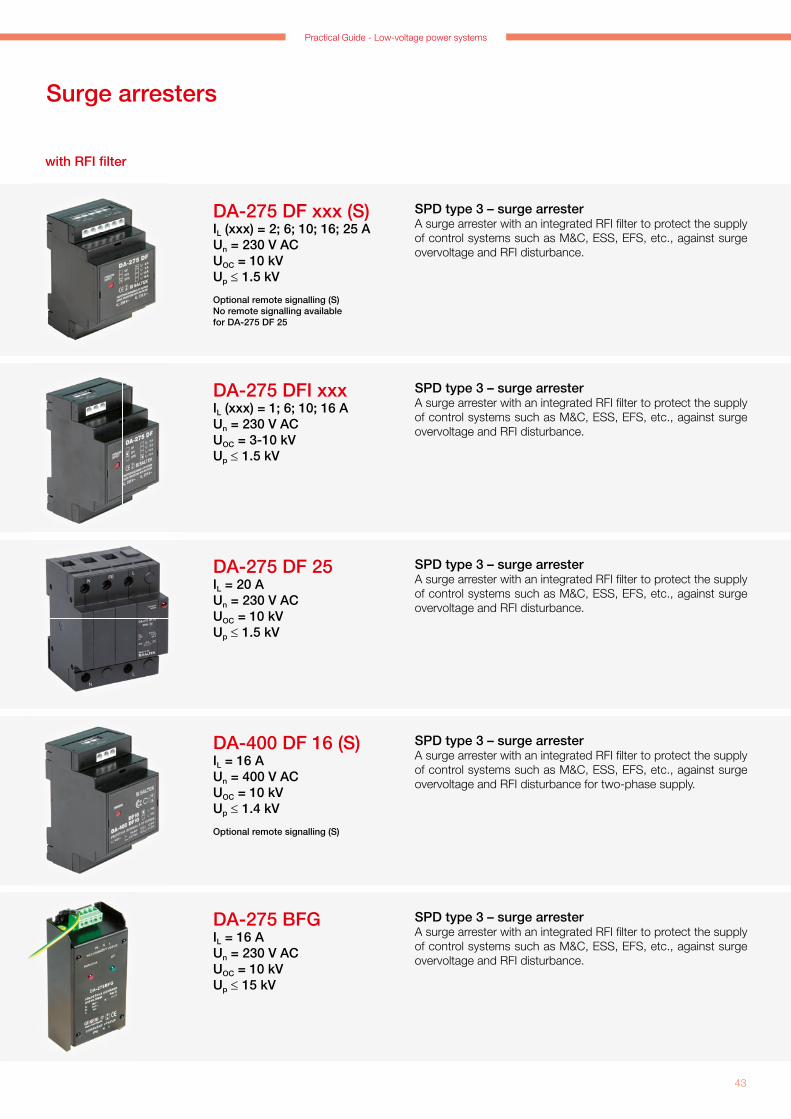
Practical Guide - Low-voltage power systems
43
Surge arresters
DA-275 DF 25IL = 20 AUn = 230 V ACUOC = 10 kVUp ≤ 1.5 kV
SPD type 3 – surge arresterA surge arrester with an integrated RFI fi lter to protect the supply of control systems such as M&C, ESS, EFS, etc., against surge overvoltage and RFI disturbance.
DA-275 DFI xxxIL (xxx) = 1; 6; 10; 16 AUn = 230 V ACUOC = 3-10 kVUp ≤ 1.5 kV
SPD type 3 – surge arresterA surge arrester with an integrated RFI fi lter to protect the supply of control systems such as M&C, ESS, EFS, etc., against surge overvoltage and RFI disturbance.
DA-400 DF 16 (S)IL = 16 AUn = 400 V ACUOC = 10 kVUp ≤ 1.4 kV
Optional remote signalling (S)
SPD type 3 – surge arresterA surge arrester with an integrated RFI fi lter to protect the supply of control systems such as M&C, ESS, EFS, etc., against surge overvoltage and RFI disturbance for two-phase supply.
DA-275 BFGIL = 16 AUn = 230 V ACUOC = 10 kVUp ≤ 15 kV
SPD type 3 – surge arresterA surge arrester with an integrated RFI fi lter to protect the supply of control systems such as M&C, ESS, EFS, etc., against surge overvoltage and RFI disturbance.
SPD type 3 – surge arrester A surge arrester with an integrated RFI fi lter to protect the supply of control systems such as M&C, ESS, EFS, etc., against surge overvoltage and RFI disturbance.
DA-275 DF xxx (S)IL (xxx) = 2; 6; 10; 16; 25 AUn = 230 V ACUOC = 10 kVUp ≤ 1.5 kV
Optional remote signalling (S) No remote signalling available for DA-275 DF 25
with RFI fi lter

44
Surge arresters
DA-275 AUn = 230 V ACIn = 2 kA (8/20 µs)UOC = 4 kV ACUp ≤ 1.5 kV
Acoustic status signalling
SPD type 3 – surge arresterSurge arresters for additional mounting in appliances, devices, machines, equipment, etc., specifi ed to protect all types of LV electrical and electronic equipment against surge overvoltage. It is suitable for single-phase supply networks, without the need to comply with the connection of the L, N conductors in the installation. It can also be used for single-phase supply networks with a separating transformer.
DA-275 CZSUn = 230 V ACIn = 3 kA (8/20 µs)UOC = 6 kVUp ≤ 1.5 kV
Remote signalling is potential-free break contact
SPD type 3 – surge arresterSurge arresters for additional mounting in appliances, devices, machines, equipment, etc., specifi ed to protect all types of LV electrical and electronic equipment against surge overvoltage.
DA-275 SUn = 230 V ACIn = 2 kA (8/20 µs)UOC = 4 kV ACUp ≤ 1.5 kV
Status remote signalling
SPD type 3 – surge arresterSurge arresters for additional mounting in appliances, devices, machines, equipment, etc., specifi ed to protect all types of LV electrical and electronic equipment against surge overvoltage. It is suitable for single-phase supply networks, without the need to comply with the connection of the L, N conductors in the in-stallation. It can also be used for single-phase supply networks with a separating transformer.
ISG-A100Iimp= 100 kA (10/350 µs)Isolation resistance >100 kΩclassifi cation – H class
Isolating spark gapIt is used for the indirect connection of an external lightning protec-tion system to other close metallic parts, where a direct connection is not allowed due to operating conditions: earthing systems of heavy current installations, telecommunications systems, auxiliary and rail earthing bars of earth short-circuit breakers triggered by the voltage, AC and DC rail earthing bars, measurement earth-ing bars for laboratories, installations with cathodic protection and stray current systems, service entry poles for external LV cables, by-pass of isolated fl anges and isolated connections to pipes.
SPD type 3 – surge arrester Surge arresters for additional mounting in appliances, devices, machines, equipment, etc., specifi ed to protect all types of LV electrical and electronic equipment against surge overvoltage.
CZ-275 AUn = 230 V ACIn = 3 kA (8/20 µs)UOC = 6 kVUp ≤ 1.5 kV
CZ-275 A - Acoustic status signalling
For additional mounting
Others
Practical Guide - Low-voltage power systems
45
SALTEK order numbers
EAN order number Material title
Spark gaps
8595090540540 FLP-SG50 V/1
8595090540533 FLP-SG50 VS/1
8595090518822 FLP-A35
Spark gaps between N and PE
8595090535737 FLP-A50N VS/NPE
8595090535744 FLP-A100N VS/NPE
Combined lightning current arresters SPD type 1
8595090553007 FLP-25-T1-V/3
8595090553045 FLP-25-T1-V/3+1
8595090553021 FLP-25-T1-V/4
8595090553014 FLP-25-T1-VS/3
8595090553052 FLP-25-T1-VS/3+1
8595090553038 FLP-25-T1-VS/4
Combined lightning current arresters SPD type 1+0
8595090535331 FLP-B+C MAXI VS/1
8595090537830 FLP-B+C MAXI VS/1+1
8595090537847 FLP-B+C MAXI VS/2
8595090535706 FLP-B+C MAXI VS/3
8595090535720 FLP-B+C MAXI VS/3+1
8595090535713 FLP-B+C MAXI VS/4
8595090550914 FLP-B+C MAXI V/1
8595090550952 FLP-B+C MAXI V/1+1
8595090550921 FLP-B+C MAXI V/2
8595090550938 FLP-B+C MAXI V/3
8595090550969 FLP-B+C MAXI V/3+1
8595090550945 FLP-B+C MAXI V/4
Varistor lightning current arresters SPD type 1+2
8595090534211 FLP-12.5 V/1
8595090534228 FLP-12.5 V/1 S
8595090534235 FLP-12.5 V/1+1
8595090534242 FLP-12.5 V/1S+1
8595090538097 FLP-12.5 V/2
8595090551829 FLP-12.5 V/2 S
8595090534259 FLP-12.5 V/3
8595090534266 FLP-12.5 V/3 S
8595090534273 FLP-12.5 V/3+1
8595090534280 FLP-12.5 V/3S+1
8595090534297 FLP-12.5 V/4
8595090534303 FLP-12.5 V/4 S
Coordination impedance
8595090514329 RTO-16
8595090514336 RTO-35
8595090514343 RTO-63
Surge arresters SPD type 2
8595090518150 SLP-075 V/1
8595090518235 SLP-075 V/1 S
8595090521556 SLP-075 VB/1
8595090521563 SLP-075 VB/1 S
8595090521822 SLP-130 VB/1
8595090529965 SLP-130 VB/1 S
8595090551850 SLP-150 V/1
EAN order number Material title
8595090551867 SLP-150 V/1 S
8595090516170 SLP-275 V/1
8595090516187 SLP-275 V/1 S
8595090519485 SLP-275 V/1+1
8595090524915 SLP-275 V/1S+1
8595090516194 SLP-275 V/2
8595090551836 SLP-275 V/2 S
8595090517603 SLP-275 V/3
8595090517610 SLP-275 V/3 S
8595090519461 SLP-275 V/3+1
8595090520023 SLP-275 V/3S+1
8595090517221 SLP-275 V/4
8595090517634 SLP-275 V/4 S
8595090519447 SLP-275 VB/1
8595090519454 SLP-275 VB/1 S
8595090533108 SLP-275 VB/3+1
8595090533115 SLP-275 VB/3S+1
8595090519553 SLP-385 V/1
8595090527718 SLP-385 V/1 S
8595090518174 SLP-440 V/1
8595090518259 SLP-440 V/1 S
8595090533016 SLP-600 V/1
8595090533023 SLP-600 V/1 S
Surge arresters SPD type 3
8595090533191 DA-075 DJ
8595090521891 DA-130 DJ
8595090506362 DA-275 DJ
8595090518723 DA-275 V/1+1
8595090519751 DA-275 V/1S+1
8595090518488 DA-275 V/3+1
8595090518495 DA-275 V/3S+1
Sockets with SPD type 3
8595090529583 DA-275 PP ELEMENT 03
8595090529590 DA-275 PP ELEMENT 04
8595090529606 DA-275 PP ELEMENT 07
8595090506423 DA-275 PP K B1 white
8595090506409 DA-275 PP K D2 beige
8595090506416 DA-275 PP K H3 brown
8595090529613 DA-275 PP TANGO beige
8595090506478 DA-275 PP TANGO white
8595090529620 DA-275 PP TANGO grey
8595090529637 DA-275 PP TIME 01
8595090529651 DA-275 PP TIME 08
8595090529668 DA-275 PP1 ELEMENT 03
8595090529675 DA-275 PP1 ELEMENT 04
8595090529682 DA-275 PP1 ELEMENT 07
8595090507222 DA-275 PP1 K B1 white
8595090506454 DA-275 PP1 K D2 beige
8595090506461 DA-275 PP1 K H3 brown
8595090529699 DA-275 PP1 PRAKTIK white
8595090528487 DA-275 PP1 PROFIL white
8595090528517 DA-275 PP1 PROFIL K
8595090528494 DA-275 PP1 PROFIL carmine
8595090529705 DA-275 PP1 REFLEX SI alpine white
8595090529712 DA-275 PP1 REFLEX SI brown
8595090529729 DA-275 PP1 REFLEX SI orange
8595090529736 DA-275 PP1 REFLEX SI green
8595090529743 DA-275 PP1 REFLEX SI yellow

46
SALTEK order numbers
EAN order number Material title
8595090529750 DA-275 PP1 TANGO beige
8595090506508 DA-275 PP1 TANGO white
8595090529767 DA-275 PP1 TANGO grey
8595090529774 DA-275 PP1 TIME 01
8595090529798 DA-275 PP1 TIME 08
8595090528463 DA-275 PP1A PROFIL white
8595090528500 DA-275 PP1A PROFIL K
8595090528470 DA-275 PP1A PROFIL carmine
8595090528159 DA-275 PPO ELEMENT 01
8595090528166 DA-275 PPO ELEMENT 03
8595090528173 DA-275 PPO ELEMENT 04
8595090528180 DA-275 PPO ELEMENT 07
8595090528197 DA-275 PPO ELEMENT 21
8595090528203 DA-275 PPO ELEMENT 22
8595090528210 DA-275 PPO ELEMENT 23
8595090528227 DA-275 PPO ELEMENT 24
8595090528104 DA-275 PPO TANGO beige
8595090528081 DA-275 PPO TANGO white
8595090528098 DA-275 PPO TANGO ivory
8595090528142 DA-275 PPO TANGO grey
8595090528234 DA-275 PPO TIME 01
8595090528258 DA-275 PPO TIME 03
8595090528265 DA-275 PPO TIME 08
8595090528289 DA-275 PPO TIME 32
8595090528296 DA-275 PPO TIME 33
8595090528302 DA-275 PPO TIME 34
8595090527923 DA-275 PPOA ELEMENT 01
8595090527930 DA-275 PPOA ELEMENT 03
8595090527947 DA-275 PPOA ELEMENT 04
8595090527954 DA-275 PPOA ELEMENT 07
8595090527961 DA-275 PPOA ELEMENT 21
8595090527978 DA-275 PPOA ELEMENT 22
8595090527985 DA-275 PPOA ELEMENT 23
8595090527992 DA-275 PPOA ELEMENT 24
8595090527879 DA-275 PPOA TANGO beige
8595090527855 DA-275 PPOA TANGO white
8595090527862 DA-275 PPOA TANGO ivory
8595090527916 DA-275 PPOA TANGO grey
8595090528005 DA-275 PPOA TIME 01
8595090528029 DA-275 PPOA TIME 03
8595090528036 DA-275 PPOA TIME 08
8595090528050 DA-275 PPOA TIME 32
8595090528067 DA-275 PPOA TIME 33
8595090528074 DA-275 PPOA TIME 34
PP - double-socketPP1 - single socketPPO - double socket with turned slotPPOA - double socket with turned slot and acoustic signalling
Surge arresters SPD type 3 with RFI filter
8595090506706 DA-275 DF 2
8595090516248 DA-275 DF 2 S
8595090506713 DA-275 DF 6
8595090516255 DA-275 DF 6 S
8595090506720 DA-275 DF 10
8595090516262 DA-275 DF 10 S
8595090506737 DA-275 DF 16
8595090516279 DA-275 DF 16 S
8595090537328 DA-275 DF 25
EAN order number Material title
8595090512059 DA-275 DFI 1
8595090508205 DA-275 DFI 6
8595090507949 DA-275 DFI 10
8595090507956 DA-275 DFI 16
8595090515074 DA-400 DF 16
8595090525660 DA-400 DF 16 S
8595090506294 DA-275 BFG
Surge arresters SPD type 3 for additional mounting
8595090540632 CZ-275 A
8595090540472 DA-275 A
8595090540625 DA-275 S
8595090519164 DA-275 CZS
Others
8595090535904 ISG-A100


SALTEK TRADE s.r.o.Vodňanská 1419/226198 00 Praha 9 - KyjeCzech RepublicPhone: +420 272 942 470Fax: +420 267 913 411E-mail: [email protected]/en