PRACTICAL FILE AUTOCAD (2D & 3D) - Jasdeep...
19
www.jasdeepsingh.in PRACTICAL FILE AUTOCAD (2D & 3D) Mechanical Department R.I.M.T. Polytechnic College (Mandi Gobindgarh) SUBMITTED TO: SUBMITTED BY: Mr. Sunil Dang Manish Kumar Jaiswal (Department of Mechanical (Mechanical Engg.)
Transcript of PRACTICAL FILE AUTOCAD (2D & 3D) - Jasdeep...
www.jasdeepsingh.in
PRACTICAL FILE AUTOCAD (2D & 3D)
Mechanical Department
R.I.M.T. Polytechnic College (Mandi Gobindgarh)
SUBMITTED TO: SUBMITTED BY:
Mr. Sunil Dang Manish Kumar Jaiswal
(Department of Mechanical (Mechanical Engg.)

www.jasdeepsingh.in
Engineering) Roll No. – 12091
Acknowledgement
Any endeavour cannot lead to success unless and until a proper
platform is provided for the same. This is the reason I find myself
very fortunate to have undergone my classes of Auto CAD in 5th
Semester at RIMT Polytechnic College, Mandi Gobindgarh.
I am highly thankful to Mr. SUNIL DANG (Department of Mechanical
Engineering, RIMT Polytechnic College), for supporting me with their
knowledge and expertise and infusing with in attitude of a dedicated
profession who gave lectures and rendered very useful information on
the various aspects of Auto CAD 2D & 3D designs.
And last but not the least I am very thankful to all friends and
fellow classmates for intending their corporation during the completion
of the classes.
With deep gratitude,
Manish Kumar Jaiswal
Diploma (Mechanical Engg)

www.jasdeepsingh.in
INDEX
Sr. No. Section Page No.
01.
Introduction to Auto CAD commands. 1.1 Concept. 1.2 Drawing Commands. 1.3 Editing Commands. 1.4 Dimensioning And Planning text in drawing area. 1.5 Sectioning and Hatching. 1.6 Inquiry of different parameters of drawing entity.
02.
Detail and Assembly drawing of the following using Auto CAD. 2.1 Plumber Block. 2.2 Wall Bracket. 2.3 Stepped Pulley, V-belt pulley. 2.4 Flanged Coupling. 2.5 Machine tool holder. 2.6 Screw Jack Or Knuckle Joint.
03.
Isometric Drawing by CAD using Auto CAD. Drawing of following on computer 3.1 Cone. 3.2 Cylinder. 3.3 Isometric view of objects.
04.
Modelling 3D Modelling, Transformation, Scaling, Rotation and Translation.
05.
Introduction to other CAD Software. (Pro-E – Features, Simple drawing of components in 2D & 3D).

www.jasdeepsingh.in
Introduction to Auto CAD
AutoCAD is a commercial software application for 2D and 3D computer-aided
design (CAD) and drafting — available since 1982 as a desktop application and
since 2010 as a mobile web- and cloud-based app marketed as AutoCAD 360.
Developed and marketed by Autodesk, Inc. AutoCAD was first released in
December 1982, running on microcomputers with internal graphics
controllers. Prior to the introduction of AutoCAD, most commercial CAD
programs ran on mainframe computers or minicomputers, with each CAD operator
(user) working at a separate graphics.
AutoCAD is used across a wide range of industries, by architects, project
managers, engineers, designers, and other professionals. It is supported by 750
training centres worldwide as of 1994.
As Autodesk's flagship product, by March 1986 AutoCAD had become the most
ubiquitous CAD program worldwide. As of 2014, AutoCAD is in its twenty-ninth
generation, and collectively with all its variants, continues to be the most widely
used CAD program throughout most of the world.
HISTORY
AutoCAD was derived from a program begun in 1977 and released in 1979
called Interact CAD, also referred to in early Autodesk documents as Micro CAD,
which was written prior to Autodesk's (then Marin chip Software Partners)
formation by Autodesk cofounder Mike Riddle.
The first version by the Autodesk Company was demonstrated at the
1982 Comdex and released that December. The 2015 release marked the 29th
major release for the AutoCAD for Windows. The 2014 release marked the fourth
consecutive year for AutoCAD for Mac.

www.jasdeepsingh.in
DRAWING COMMON COMMANDS
SHORTCUT COMMAND COMMENT
A ARC Draw an arc
AR ARRAY Opens array dialogue box
C CIRCLE Draw a circle
CHA CHAMFER Chamfer between 2 non-parallel lines
F FILLET Draw an arc between 2 intersecting lines
H HATCH Opens hatch and gradient dialogue box
J JOIN Joins 2 objects to form single object
L LINE Draw a line
LE QLEADER Draw a leader line (may need to adjust settings)
O OFFSET Offset a selection
T MTEXT Insert multiline text
TR TRIM Trim a selection UN UNITS Opens units dialogue box
X EXPLODE Explode a selection Z ZOOM Zoom in display - A=All, E=EXTENTS,
W=WINDOW
CONTROL KEYS
CTRL+A Select all
CTRL+C COPYCLIP Copies objects to clipboard
CTRL+J Repeats last command
CTRL+N NEW Opens create new drawing dialogue box
CTRL+O OPEN Opens the select file dialogue box
CTRL+S QSAVE Opens the save drawing as dialogue box
CTRL+Y REDO Performs the operation cancelled by UNDO
CTRL+Z UNDO Undoes the last operation

www.jasdeepsingh.in
DRAWING OBJECTS
SHORTCUT COMMAND COMMENT
A ARC Draw an arc with 3 points B
BLOCK
Opens block dialogue box in order to make a block
BO BOUNDARY Draw a boundary C CIRCLE Draw a circle
EL
ELLIPSE
Draw an ellipse
F FILLET Draw an arc between 2 intersecting
lines
H
HATCH
Opens hatch and gradient dialogue box
L
LINE
Draw a line
LE QLEADER Draw a leader line (may need to adjust settings)
O
OFFSET
Offset an object by distance
PL PLINE Draw a polyline - a complex line
POL POLYGON Draw a regular polygon 3 to 1024 sides
SPL SPLINE Spline or smooth curve along points
T MTEXT Multi-line text
TEXT
SHORTCUT COMMAND COMMENT
%%C Ø Diameter dimensioning symbol
%%D ° Degrees symbol
%%O OVERSCORE Toggles over score mode on/off
%%P
±
Plus/minus symbol
%%U UNDERSCORE Toggles underscore on/off
www.jasdeepsingh.in
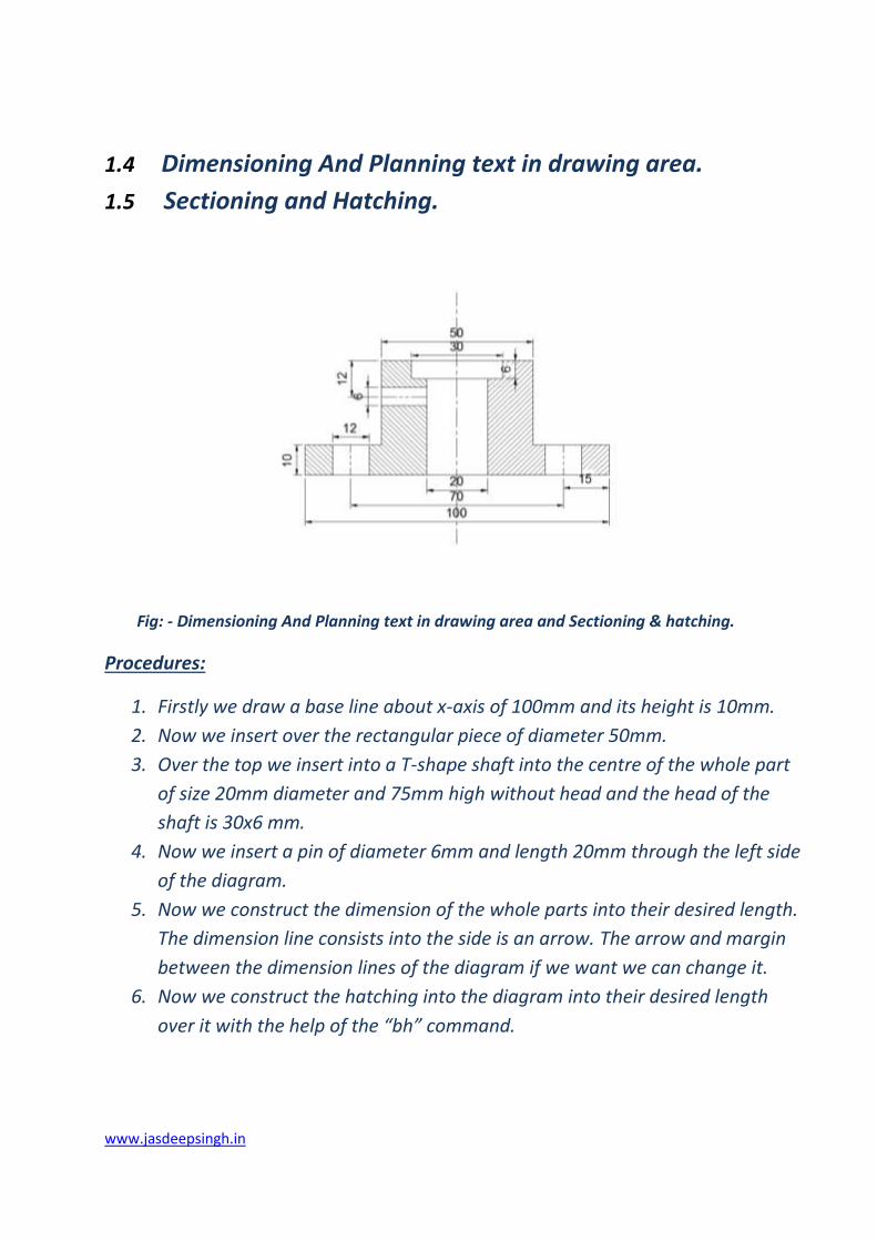
1.4 Dimensioning And Planning text in drawing area.
1.5 Sectioning and Hatching.
Fig: - Dimensioning And Planning text in drawing area and Sectioning & hatching.
Procedures:
1. Firstly we draw a base line about x-axis of 100mm and its height is 10mm.
2. Now we insert over the rectangular piece of diameter 50mm.
3. Over the top we insert into a T-shape shaft into the centre of the whole part
of size 20mm diameter and 75mm high without head and the head of the
shaft is 30x6 mm.
4. Now we insert a pin of diameter 6mm and length 20mm through the left side
of the diagram.
5. Now we construct the dimension of the whole parts into their desired length.
The dimension line consists into the side is an arrow. The arrow and margin
between the dimension lines of the diagram if we want we can change it.
6. Now we construct the hatching into the diagram into their desired length
over it with the help of the “bh” command.

www.jasdeepsingh.in
Detail and Assembly drawing of the following using Auto CAD
commands.
2.1 Plumber Block
Procedure of plumber block:
1. Draw a base line about the x- axis of 164 mm.
2. Now from the base line draw another line perpendicular to the base line from
its right end of 11mm.
3. The body height should be kept not more than 54 mm and it’s material is
made of C.I (cast iron).
4. Now draw a perpendicular centre line from the base line of desired length.
5. From the centre of the centre line draw 3 concentric circles of radii 20, 18 and
13 mm resp. This portion is called as the brass section.(made of gun metal).
6. Draw a semi-circle from the same centre of radius 25mm.
7. In order to draw the cap draw an arc of radius 38mm with centre line as its
centre.
8. Now draw the base of bolt section of dimension 6x 18mm.
9. For the bolt itself the size is 73x10 mm comprising of thread length 22mm
and it is made of mild steel M.I.
10. Two nuts are to apply on this bolt namely the lock nut (6x18mm) and a
formal nut (10x18), both made of mild steel.
www.jasdeepsingh.in
11. Do the same procedure for the remaining other half portion of the section.
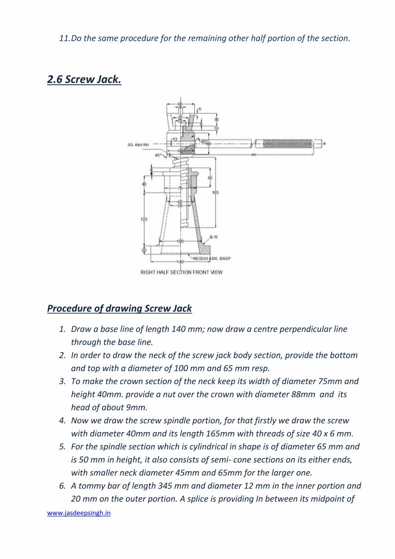
2.6 Screw Jack.
Procedure of drawing Screw Jack
1. Draw a base line of length 140 mm; now draw a centre perpendicular line
through the base line.
2. In order to draw the neck of the screw jack body section, provide the bottom
and top with a diameter of 100 mm and 65 mm resp.
3. To make the crown section of the neck keep its width of diameter 75mm and
height 40mm. provide a nut over the crown with diameter 88mm and its
head of about 9mm.
4. Now we draw the screw spindle portion, for that firstly we draw the screw
with diameter 40mm and its length 165mm with threads of size 40 x 6 mm.
5. For the spindle section which is cylindrical in shape is of diameter 65 mm and
is 50 mm in height, it also consists of semi- cone sections on its either ends,
with smaller neck diameter 45mm and 65mm for the larger one.
6. A tommy bar of length 345 mm and diameter 12 mm in the inner portion and
20 mm on the outer portion. A splice is providing In between its midpoint of

www.jasdeepsingh.in
the outside portion of the bar. A little knurling is done on both tommy bars as
well as on the screw spindle.
7. A cap is provided at the top screw spindle section of diameter 45 mm and
height 40 mm. the cup is in the shape of a trapezoid in 2D, so that its base
length is 45mm and its top length is 65mm.
8. In order to join the cup and the screw spindle a CSK screw is provide. The CSK
screw is 25mm inside the spindle and its remaining 8 mm portion is fixed in
the cup.
9. An oil hole is also provided at the central top portion of the cup with
diameter 9mm.

www.jasdeepsingh.in
2.2 Wall Bracket.
Procedure of Front View Wall Bracket:
1. It is a sort of a triangular shaped object, with its perpendicular sides of
lengths 720mm and 685mm resp.
2. One of the lengths is extended upto 150mm. the sides of the triangle are
given an offset of 30mm on the shorter side and 25mm on the longer side on
the boundaries and 90mm, 75mm and 100mm on the longer, shorter and the
hypotenuse sides.
3. Now join the hypotenuse line of the two sides of the triangle in order to
complete the triangle.
4. Now fillet the extreme portions of the hypotenuse line with radii 114mm and
180mm on the upper and lower side resp.
5. Pedestal bolt holes and spotfaced bolt holes are provided at intermediate
distances at the ends at a distance of 316 mm respectively at their central
point on the longer side and 555mm on the central point of the shorter side.
www.jasdeepsingh.in
Procedure of left side View Wall Bracket:
1. Draw the left side view wall bracket of base line of length 250mm and its
height of 685mm respectively.
2. Its include inside it’s of left side of length 570mm and width of 55mm and
right side of length 570mm and width 175mm and it contains a gap between
them of 20mm.
3. Draw the bolt holes of diameter of 30mm in its remaining parts.
Procedure of Top View Wall Bracket:
1. Draw a rectangle of size 25x250mm
2. Now draw another rectangle of dimension 116 x 685mm resp.
3. Now using the fillet command provide curves of radius 380mm on both the
edges of the larger rectangle.
4. Provide 2 pedestal bolt holes in between the top of the wall bracket with a
gap of 316 mm of size 35 x 25mm resp.

www.jasdeepsingh.in
2.5 Machine tool holder.
Procedure for Machine tool Holder:

www.jasdeepsingh.in
1. Firstly a base plate is provided with dimension 150 x 34 mm, a cutting is
made on both the ends of the rectangular base plate of 9mm deep and
45mm in length.
2. On the left end of the base plate a grub screw is inserted, which is size 32 x
17 mm without the head section while the head section is of diameter 25mm
and 12 mm high.
3. Now a tool holder is provided over the base plate of given size ( say 90mm
high and 150mm wide)
4. To provide a flexible joint between the base plate and the tool holder a spring
of diameter 7 mm and 30mm high.
5. A mover is provided at the middle top of the tool holder which is in the shape
of a polygon which is 46mm high and has a diameter of 62mm.
6. A stud is a rectangular shaped object which is provided in between the tool
holder and is of size 160 x 24 mm.
7. A rectangular handle of size 114 x 10 mm is provided on the right side of the
mover. A knob ebonite is applied over the handle which consists of threads
and is of diameter 40 mm and it is spherical in shape.
8. A couple of set screws are inserted on either ends of the tool holder, the set
screws consist of three layered coating with diameters as 22 >16>10 mm
resp. The head section is 22 mm wide while the bottom is 56mm.
www.jasdeepsingh.in
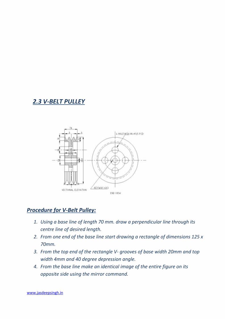
2.3 V-BELT PULLEY
Procedure for V-Belt Pulley:
1. Using a base line of length 70 mm. draw a perpendicular line through its
centre line of desired length.
2. From one end of the base line start drawing a rectangle of dimensions 125 x
70mm.
3. From the top end of the rectangle V- grooves of base width 20mm and top
width 4mm and 40 degree depression angle.
4. From the base line make an identical image of the entire figure on its
opposite side using the mirror command.
www.jasdeepsingh.in
5. For the boundaries on the top and bottom portion of the figure leave a gap
of 25 mm from the top of the rectangular side end extend it till 24mm then
again extend it in the downward direction till 20mm. Copy and paste this in
the front opposite direction.
6. Using the polyline command draw a line 25mm high from the base line then
21mm on the right side. A gap of 3 mm is left on its side. Copy this and paste
it on the right opposite side.
7. The entire above section is then copied or mirrored in order to obtain an
image on the downward side.
8. A desired hatching portion is left on the bottom of the figure.
9. Hatching is done on both top and bottom portions according to the
requirements of the diagram.
PTC Creo Elements/Pro
PTC Creo, formerly known as Pro/ENGINEER is a parametric, integrated
3D CAD/CAM/CAE solution created by Parametric Technology Corporation (PTC).
It was the first to market with parametric, feature-based, associative solid
modeling software. The application runs on Microsoft Windows platform, and
provides solid modeling, assembly modelling and drafting, finite element analysis,
direct and parametric modelling, sub-divisional and nurbs surfacing, and NC and
tooling functionality for mechanical engineers. It features a suite of 10
applications which work within the same program. Versions for UNIX systems were
discontinued after the release of version 4.0, except Solaris on x86-64.
The Pro/ENGINEER name was changed to Creo Elements/Pro, also known as
Wildfire 5.0 on October 28, 2010, coinciding with PTC’s announcement of Creo,
a new design software application suite. Creo Elements/Pro will be discontinued
after version 2 in favour of the Creo design suite.
Creo Elements/Pro and now Creo Parametric compete in the market
with CATIA and Siemens NX.
OVERVIEW

www.jasdeepsingh.in
Engineering Design
Creo Elements/Pro offers a range of tools to enable the generation of
a complete digital representation of the product being designed. In addition to
the general geometry tools there is also the ability to generate geometry
of other integrated design disciplines such as industrial and standard pipe work and
complete wiring definitions. Tools are also available to support collaborative
development.
Analysis
Creo Elements/Pro has numerous analysis tools available and covers thermal,
static, dynamic and fatigue finite element analysis along with other tools all
designed to help with the development of the product. These tools include human
factors, manufacturing tolerance, mould flow and design optimization. The design
optimization can be used at a geometry level to obtain the optimum design
dimensions and in conjunction with the finite element analysis.
Manufacturing
By using the fundamental abilities of the software with regards to the single
data source principle, it provides a rich set of tools in the manufacturing
environment in the form of tooling design and simulated CNC machining and
output.
Tooling options cover specialty tools for molding, die-casting and
progressive tooling design.
www.jasdeepsingh.in
1. Using the polyline command on the 2D frame, draw the diagram with given
dimensions.
2. Now using the extrude command with an elevation of 10mm, raise the entire
figure.
3. From the extreme end of the 3D figure, again draw a square using polyline
command of the given dimensions and extrude it to an elevation of 20mm.
4. Similarly two other cuboidal 3D figures are drawn on other two extreme sides
of the figure.
5. Now select the entire figure and apply the region command to it in order to
select the entire boundary as one.
6. Similarly, using the union command select the entire region and form a union
figure.
7. Show all the necessary dimensions of the figure, using the linear dimension
command.
8. Now through the navigation bar we can move or rotate the diagram
according to x, y, and z axes.