Practical Digital Signal Processing using Microcontrollers - Elektor
22
Transcript of Practical Digital Signal Processing using Microcontrollers - Elektor


Practical Digital Signal Processing using Microcontrollers
Prof Dr Dogan Ibrahim Near East University

Copyri
ght E
lektor
ACKNOWLEDGEMENTS
The following material is reproduced in this book with the kind permission of the respective copyright holders and may not be reprinted, or reproduced in any way, without their prior consent.
Figures A.1 – A.11 are taken from Microchip Technology Inc. Data Sheet PIC18(L)F2X/4XK22 (DS41412F). Figures 3.1 – 3.3, 3.9, 12.4 are taken from the web site of Microchip Technology Inc.
Figure 3.4 is taken from the web site of Custom Computer Services Inc.
Figures 3.6 – 3.8, 12.2, 12.4 are taken from the web site of mikroElektronica.
Figure 3.5 is taken from the web site of Olimex.
Figures 3.10 - 3.12, 14.1 – 14.3 are taken from the web site of Analog Devices Inc.
Figure 3.13 is taken from the web site of Texas Instruments Inc.
Figure 3.14 is taken from the web site of Freescale Semiconductors Inc.
PIC®, PICSTART®, and MPLAB® are all trademarks of Microchip Technology Inc.

Copyri
ght E
lektor
5
Contents
INTRODUCTION ........................................................................... 17 CHAPTER 1 -
1.1 BACKGROUND ....................................................................................................... 17 1.2 A TYPICAL DSP APPLICATION ................................................................................... 18 1.3 THE ANTI-ALIASING ANALOG FILTER ........................................................................... 18 1.4 SAMPLE AND HOLD CIRCUIT ..................................................................................... 21 1.5 A/D CONVERTER ................................................................................................... 21 1.6 DSP ................................................................................................................... 24 1.7 D/A CONVERTER ................................................................................................... 24 1.8 EXERCISES ............................................................................................................ 25
NUMBER SYSTEMS ...................................................................... 27 CHAPTER 2 -
2.1 FIXED POINT NUMBERS ........................................................................................... 27 2.1.1 Decimal Number System ............................................................................ 28 2.1.2 Binary Number System .............................................................................. 28 2.1.3 Octal Number System ................................................................................ 29 2.1.4 Hexadecimal Number System .................................................................... 29 2.1.5 Converting Binary Numbers into Decimal .................................................. 30 2.1.6 Converting Decimal Numbers into Binary .................................................. 31 2.1.7 Converting Binary Numbers into Hexadecimal ........................................... 33 2.1.8 Converting Hexadecimal Numbers into Binary ........................................... 34 2.1.9 Converting Hexadecimal Numbers into Decimal ........................................ 35 2.1.10 Converting Decimal Numbers into Hexadecimal ........................................ 36 2.1.11 Converting Octal Numbers into Decimal .................................................... 37 2.1.12 Converting Decimal Numbers into Octal .................................................... 38 2.1.13 Converting Octal Numbers into Binary ....................................................... 39 2.1.14 Converting Binary Numbers Into Octal ....................................................... 40 2.1.15 Negative Numbers ..................................................................................... 40 2.1.16 Adding Binary Numbers ............................................................................. 42 2.1.17 Subtracting Binary Numbers ...................................................................... 43 2.1.18 Multiplication of Binary Numbers .............................................................. 43 2.1.19 Division of Binary Numbers ........................................................................ 45 2.1.20 Signed Magnitude Representation ............................................................. 45 2.1.21 Offset Binary Representation ..................................................................... 46

Copyri
ght E
lektor
6
2.1.22 Fractional Fixed Point Numbers ................................................................. 47 2.1.23 Converting Fractional Number into Integer ................................................ 48 2.1.24 Converting from Integer into Fractional Number ....................................... 48
2.2 FLOATING POINT NUMBERS ..................................................................................... 49 2.2.1 Converting a Floating Point Number into Decimal ..................................... 50 2.2.2 Normalizing the Floating Point Numbers ................................................... 51 2.2.3 Converting a Decimal Number into Floating Point ..................................... 52 2.2.4 Multiplication and Division of Floating Point Numbers............................... 53 2.2.5 Addition and Subtraction of Floating Point Numbers ................................. 55
2.3 FIXED POINT OR FLOATING POINT NUMBERS IN DSP OPERATIONS .................................... 56 2.4 BCD NUMBERS ..................................................................................................... 57 2.5 THE ASCII TABLE ................................................................................................... 58 2.6 SUMMARY ........................................................................................................... 59 2.7 EXERCISES ............................................................................................................ 60
DIGITAL SIGNAL PROCESSORS ............................................... 65 CHAPTER 3 -
3.1 CHOOSING A DDSP PROCESSOR ............................................................................... 66 3.2 DSP HARDWARE DEVELOPMENT TOOLS ..................................................................... 68
3.2.1 General Purpose Microcontroller Development Tools ................................ 68 3.2.2 DSP-Enhanced Processor Development Tools ............................................. 75 3.2.3 Dedicated DSP Processor Development Tools ............................................ 80
3.3 DSP SOFTWARE DEVELOPMENT TOOLS ...................................................................... 83 3.3.1 General Purpose Microcontroller Software Development Tools ................. 83 3.3.2 DSP-Enhanced Processor Software Development Tools .............................. 84 3.3.3 Dedicated DSP Processor Software Development Tools.............................. 85
3.4 EXERCISES ............................................................................................................ 86
MIKROC PRO PROGRAMMING LANGUAGE FOR CHAPTER 4 -MICROCONTROLLERS .................................................................. 87
4.1 C LANGUAGES FOR MICROCONTROLLERS ..................................................................... 87 4.2 YOUR FIRST MIKROC PRO FOR PIC PROGRAM .............................................................. 89
4.2.1 Comments ................................................................................................. 90 4.2.2 Beginning and Ending a Program .............................................................. 90 4.2.3 White Spaces ............................................................................................. 91 4.2.4 Variable Names ......................................................................................... 92 4.2.5 Reserved Names ........................................................................................ 92 4.2.6 Variable Types ........................................................................................... 93

Copyri
ght E
lektor
7
4.2.7 Constants .................................................................................................. 95 4.2.8 Escape Sequences ...................................................................................... 96 4.2.9 Accessing Bits of a Variable ....................................................................... 96 4.2.10 sbit Type .................................................................................................... 97 4.2.11 bit Type ..................................................................................................... 97 4.2.12 Arrays ........................................................................................................ 97 4.2.13 Pointers ................................................................................................... 100 4.2.14 Structures ................................................................................................ 102 4.2.15 Operators in mikroC Pro for PIC ............................................................... 105 4.2.16 The Flow of Control ................................................................................. 109
4.3 FUNCTIONS IN MIKROC PRO FOR PIC ....................................................................... 118 4.3.1 void Functions ......................................................................................... 119 4.3.2 Passing Parameters to Functions ............................................................. 119 4.3.3 Passing Arrays to Functions ..................................................................... 120 4.3.4 Interrupt Processing ................................................................................ 121
4.4 MIKROC PRO FOR PIC BUILT-IN FUNCTIONS ............................................................... 122 4.5 MIKROC PRO FOR PIC LIBRARIES ............................................................................. 123 4.6 USING THE MIKROC PRO FOR PIC COMPILER.............................................................. 124
4.6.1 mikroC Pro for PIC IDE ............................................................................. 125 4.6.2 Creating a New Source File ...................................................................... 127 4.6.3 Compiling the Source File......................................................................... 130
4.7 SUMMARY ......................................................................................................... 131 4.8 EXERCISES .......................................................................................................... 132
INTRODUCTION TO MATLAB ................................................. 135 CHAPTER 5 -
5.1 GETTING STARTED ............................................................................................... 135 5.1.1 disp Command ........................................................................................ 137 5.1.2 format Command .................................................................................... 138 5.1.3 input Command ....................................................................................... 139 5.1.4 Comment lines......................................................................................... 139 5.1.5 Programming in MATLAB ........................................................................ 139 5.1.6 The Working Environment ....................................................................... 149 5.1.7 Vectors in MATLAB .................................................................................. 149 5.1.8 Matrices in MATLAB ................................................................................ 154 5.1.9 Graphics Plotting Using MATLAB ............................................................. 157
5.2 SUMMARY ......................................................................................................... 170 5.3 EXERCISES .......................................................................................................... 170

Copyri
ght E
lektor
8
DISCRETE TIME SIGNALS ....................................................... 173 CHAPTER 6 -
6.1 THE SAMPLING PROCESS ....................................................................................... 173 6.2 SOME DIGITAL SIGNAL TYPES.................................................................................. 174
6.2.1 Unit Step Function ................................................................................... 174 6.2.2 Unit Impulse Function .............................................................................. 175 6.2.3 Sinusoidal Signal ...................................................................................... 175 6.2.4 Exponential Signal ................................................................................... 177 6.2.5 Complex Exponential Signal ..................................................................... 177 6.2.6 Exponential Sinusoidal Decay Signal ........................................................ 178
6.3 OPERATIONS ON DISCRETE TIME SIGNALS .................................................................. 179 6.3.1 Delay or Shift ........................................................................................... 179 6.3.2 Vector Addition and Subtraction .............................................................. 181 6.3.3 Scalar Addition and Subtraction .............................................................. 182 6.3.4 Scalar Multiplication and Division ............................................................ 182 6.3.5 Vector Multiplication and Division ........................................................... 183
6.4 BLOCK DIAGRAM REPRESENTATION.......................................................................... 184 6.4.1 Block Diagram Manipulation ................................................................... 184
6.5 DISCRETE SYSTEM CLASSIFICATION ........................................................................... 186 6.5.1 Linear and Non-linear .............................................................................. 186 6.5.2 Time-variant and Time-invariant ............................................................. 186 6.5.3 Causal and Non-causal ............................................................................ 186 6.5.4 Stable and Unstable ................................................................................ 187 6.5.5 Linear Time-invariant Systems ................................................................. 187
6.6 THE CONVOLUTION PROCESS .................................................................................. 187 6.7 EXERCISES .......................................................................................................... 192
THE Z-TRANSFORM .................................................................. 195 CHAPTER 7 -
7.1 UNIT STEP FUNCTION ........................................................................................... 195 7.2 UNIT RAMP FUNCTION.......................................................................................... 196 7.3 EXPONENTIAL FUNCTION ....................................................................................... 197 7.4 SINE FUNCTION ................................................................................................... 198 7.5 DISCRETE IMPULSE FUNCTION ................................................................................. 199 7.6 TABLES OF Z-TRANSFORMS .................................................................................... 199 7.7 THE Z-TRANSFORM OF A FUNCTION EXPRESSED AS A LAPLACE TRANSFORM ....................... 200 7.8 PROPERTIES OF THE Z-TRANSFORM .......................................................................... 201 7.9 INVERSE Z-TRANSFORMS ....................................................................................... 204
7.9.1 Coefficients of Partial Fraction Expansion ................................................ 211

Copyri
ght E
lektor
9
7.10 EXERCISES .......................................................................................................... 214
THE DISCRETE FOURIER TRANSFORM ............................... 217 CHAPTER 8 -
8.1 THE SPECTRA OF PERIODIC SIGNALS ......................................................................... 217 8.2 PROPERTIES OF THE DFT ....................................................................................... 231 8.3 FOURIER TRANSFORM OF APERIODIC DIGITAL SIGNALS ................................................. 232 8.4 EXERCISES .......................................................................................................... 235
DIGITAL FILTERS ...................................................................... 237 CHAPTER 9 -
9.1 FIR FILTERS AND IIR FILTERS .................................................................................. 238 9.2 THE DIGITAL FILTER DESIGN PROCESS ....................................................................... 239
DESIGN OF FIR DIGITAL FILTERS ........................................ 245 CHAPTER 10 -
10.1 THE FOURIER TRANSFORM METHOD ........................................................................ 245 10.2 TRUNCATION AND WINDOWING.............................................................................. 249 10.3 SOME COMMONLY USED WINDOWING FUNCTIONS ..................................................... 250
10.3.1 Rectangular Window ............................................................................... 250 10.3.2 Hamming Window................................................................................... 252 10.3.3 Hanning Window ..................................................................................... 256 10.3.4 Blackman Window................................................................................... 256 10.3.5 Remez Exchange Based Design ................................................................ 260
10.4 USING COMPUTER AIDED TECHNIQUES FOR THE DESIGN OF FIR FILTERS .......................... 260 10.4.1 The ScopeFIR Software ............................................................................ 260
10.5 FIR DIGITAL FILTER STRUCTURES ............................................................................. 268 10.5.1 Direct FIR Structures ................................................................................ 268 10.5.2 Cascade FIR Structures ............................................................................ 269
10.6 EXERCISES .......................................................................................................... 269
DESIGN OF IIR DIGITAL FILTERS ......................................... 271 CHAPTER 11 -
11.1 IIR FILTER TRANSFER FUNCTION .............................................................................. 271 11.2 ANALOG FILTER DESIGN REVIEW ............................................................................. 272 11.3 BUTTERWORTH FILTERS ......................................................................................... 273
11.3.1 Bilinear transformation method .............................................................. 275 11.4 CHEBYSHEV FILTERS.............................................................................................. 282 11.5 ELLIPTIC FILTERS .................................................................................................. 286 11.6 THE SCOPEIIR FILTER DESIGN PROGRAM................................................................... 288 11.7 IIR FILTER STRUCTURES ......................................................................................... 289
11.7.1 Direct Structure ....................................................................................... 290
Copyri
ght E
lektor
10
11.7.2 Cascade Structure .................................................................................... 290 11.8 EXERCISES .......................................................................................................... 292
DESIGN OF FIR DIGITAL FILTERS USING CHAPTER 12 -MICROCONTROLLERS ................................................................ 295
12.1 DESIGN OF A LOW-PASS FILTER ............................................................................... 295 12.1.1 The Project Hardware .............................................................................. 295 12.1.2 Calculating the Filter Coefficients with Scope FIR Filter Design Program .. 301 12.1.3 Implementing the FIR Filter ..................................................................... 304 12.1.4 The Algorithm.......................................................................................... 305 12.1.5 Program Listing ....................................................................................... 306
12.2 DESIGN OF A BAND-PASS FILTER ............................................................................. 310 12.3 MORE EFFICIENT ALGORITHM ................................................................................. 311
12.3.1 Filter Specifications.................................................................................. 315 12.4 DESIGNING A BAND-PASS FILTER WITH MORE EFFICIENT ALGORITHM .............................. 318 12.5 CALCULATING THE TIME IN THE FIR FILTER LOOP......................................................... 320
DESIGN OF IIR DIGITAL FILTERS USING CHAPTER 13 -MICROCONTROLLERS ................................................................ 323
13.1 DESIGN OF A LOW-PASS FILTER ............................................................................... 323 13.1.1 The Project Hardware .............................................................................. 323 13.1.2 Cascade Implementation ......................................................................... 324 13.1.3 The Filter Coefficients .............................................................................. 326 13.1.4 The Filter Program ................................................................................... 328
13.2 SECOND ORDER HIGH-PASS FILTER .......................................................................... 331 13.3 SIXTH ORDER LOW-PASS FILTER .............................................................................. 332 13.4 PROGRAM FOR ANY EVEN ORDER IIR FILTER .............................................................. 335 13.5 IIR FILTERS OF ANY ORDER .................................................................................... 337 13.6 CALCULATING THE TIME IN THE IIR FILTER LOOP ......................................................... 341
GETTING STARTED WITH DEDICATED DSPS ..................... 343 CHAPTER 14 -
14.1 THE DEDICATED DSP MARKET ................................................................................ 343 14.2 THE ADSP-21469 DSP PROCESSOR ....................................................................... 344 14.3 THE ADSP-21469 EZ-BOARD DEVELOPMENT KIT ...................................................... 347 14.4 AUDIO INPUT-OUTPUT CONNECTIONS ...................................................................... 351 14.5 THE SHARC FAMILY DEVELOPMENT TOOLS ............................................................... 353 14.6 THE VISUALDSP++ .............................................................................................. 356

Copyri
ght E
lektor
11
APPENDIX A BUTTERWORTH DIGITAL FILTER COEFFICIENTS .......... 365
APPENDIX B CHEBYSHEV DIGITAL FILTER COEFFICIENTS ................. 371
APPENDIX C ARCHITECTURE OF THE PIC18F45K22 MICROCONTROLLER .................................................................. 377
C.1 THE PIC18F45K22 MICROCONTROLLER .................................................................. 377 C.2 PIC18F45K22 ARCHITECTURE ............................................................................... 378
C.2.1 The Program Memory ............................................................................. 380 C.2.2 The Data Memory ................................................................................... 381 C.2.3 Oscillator Configurations ......................................................................... 382 C.2.4 The Reset ................................................................................................. 382 C.2.5 Parallel I/O Ports ..................................................................................... 383 C.2.6 Timer Modules ........................................................................................ 384 C.2.7 Analog-to-Digital Converter Module ........................................................ 387 C.2.8 Interrupts ................................................................................................ 391
APPENDIX D PROGRAM LISTING FIR1.C ..................................................... 397
APPENDIX E PROGRAM LISTING FIR1.C (INPUT BUFFER) ...................... 401
APPENDIX F PROGRAM LISTING IIR1.C ...................................................... 405
APPENDIX G 6TH ORDER IIR DIGITAL FILTER PROGRAM ....................... 409
APPENDIX H PROGRAM LISTING EVEN NUMBER IIR FILTER ............... 413
APPENDIX I PROGRAM LISTING: MODIFIED IIR FILTER DESIGN ....... 417
INDEX .......................................................................................................................... 423

Copyri
ght E
lektor
13
PREFACE
Digital Signal Processing (DSP) is the process of capturing, analysing, and manipulation of an analog signal by a digital processor, e.g. a digital computer.
The theory of DSP is quite complex and requires good understanding of high level of mathematics. Students new to DSP are usually taught the theory in great detail with very little or no practical applications. For example, in many cases a student can derive complex equations for digital filters, but is unable to implement a digital filter in real life. Some institutions use tools such as MATLAB to derive the coefficients of digital filters and then to simulate the behaviour of these filters on a PC. Although simulation can be an invaluable tool in teaching, it is never the same as real-time and real-life implementations.
The aim of this book is to teach the basic principles of DSP and to introduce DSP from a practical point of view using minimum of mathematics. Only the basic level of theory is given just enough to implement DSP applications in real-time. The emphasis of the book is on practical aspects of DSP, such as design issues and real-time implementation issues. The practical implementation is described using the widely available low-cost general purpose microcontrollers so that the readers can very easily and quickly design and implement DSP applications in real-time. The architectures of dedicated DSP processors are complex and this adds additional difficulty to students who may want to implement DSP applications using such tools.
In this book the popular and highly powerful PIC18F45K22 microcontroller is used as the processor to implement DSP applications in real-time. Using this microcontroller the readers should be able to implement DSP applications with sampling frequencies within the audio range. Programming is done using the popular and powerful mikroC PRO for PIC, which is a “C” language and compiler developed specifically for the PIC family of microcontrollers. The DSP projects given in the book are based on using the EasyPIC 7 microcontroller development kit, although any other development kit could also be used.
The DSP development environment used in the book consists of:
• EasyPIC 7 microcontroller development board with PIC18F45K22 chip• A/D converter (built-in on the microcontroller chip)• D/A converter (MCP4921)• PCSGU250 Frequency generator and Bode plotter• mikroC PRO for PIC compiler
This book is primarily intended for students and practising engineers who may want to learn the practical implementation of DSPs, such as digital filters in real-time.

Copyri
ght E
lektor
14
The structure of the book is as follows:
Chapter 1 is an introduction to the world of DSPs and gives a brief overview of the basic parts forming a typical DSP system.
Chapter 2 is about the important topic of number systems which describes the various number systems used in microcontroller and DSP applications.
Chapter 3 is an introduction to the processor architectures used in DSP applications. The features of various hardware and software development tools are given in this chapter.
Chapter 4 is about “C” programming and describes the features of the popular mikroC PRO for PIC language and compiler in detail and with many examples.
Chapter 5 is an introduction to the powerful engineering design and simulation tool MATLAB. The basic programming and graph plotting details are given with examples.
Chapter 6 provides the basic principles of discrete time systems required for the understanding of DSP systems in general.
Chapter 7 is about the z-transforms and covers the principles of this important topic, including the inverse transformations.
Chapter 8 is an introduction to the important topic of Discrete Fourier Transforms and gives examples of finding the transform of some common functions.
Chapter 9 is about the features of digital filters and provides a comparison of various types of filters used in practice.
Chapter 10 provides the theory of designing FIR digital filters. The design of low-pass and high-pass filters is given with examples. In addition, the ScopeFIR digital filter design software package is described with examples.
Chapter 11 provides the theory of designing IIR digital filters. The design of Butterworth and Chebyshev type digital filters are given with examples. In addition, the ScopeIIR digital filter design software package is described with examples.
Chapter 12 is about the implementation of FIR digital filters using general purpose microcontrollers. Various tested and working example projects are given in this chapter, including the implementation of several different windowed designs.
Chapter 13 is about the implementation of IIR digital filters using general purpose microcontrollers. Various tested and working examples are given in this chapter, including the implementation of Butterworth and Chebyshev type filters.
Copyri
ght E
lektor
15
Chapter 14 is an introduction to the dedicated DSP processors where the use of VisualDSP++ software package is given with a simple example.
Finally, Appendix A and Appendix B give tables for the design of Butterworth and Chebyshev type digital filters respectively. Appendix C provides the architectural details of the PIC18F45K22 microcontroller used in the projects in this book. Appendix D to Appendix I give program listings of designed digital filters.
Prof Dr Dogan Ibrahim London, 2013
Copyri
ght E
lektor
6.4 | Block Diagram Representation
184
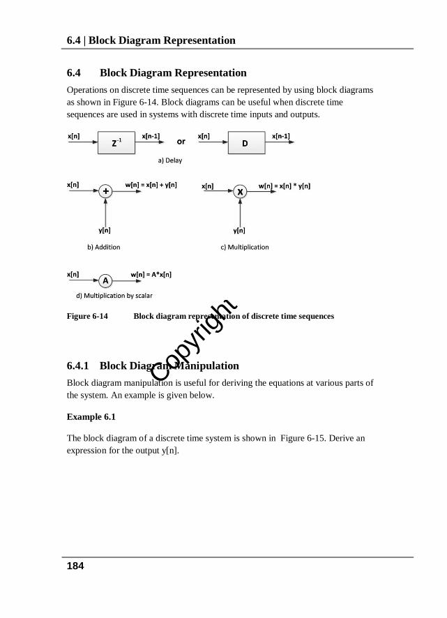
6.4 Block Diagram Representation Operations on discrete time sequences can be represented by using block diagrams as shown in Figure 6-14. Block diagrams can be useful when discrete time sequences are used in systems with discrete time inputs and outputs.
Figure 6-14 Block diagram representation of discrete time sequences
6.4.1 Block Diagram Manipulation Block diagram manipulation is useful for deriving the equations at various parts of the system. An example is given below.
Example 6.1
The block diagram of a discrete time system is shown in Figure 6-15. Derive an expression for the output y[n].

Copyri
ght E
lektor
7.8 | Properties of the z-Transform
202
𝑍[𝑎𝑥(𝑛)] = 𝑎𝑍[𝑥(𝑛)] = 𝑎𝑋[𝑧]
2. Left shift property Suppose that the z-transform of x[n] is X[z] and let y[n] = x(n + m). Then,
𝑌[𝑧] = 𝑧𝑚𝑋[𝑍]− � 𝑥(𝑖)𝑧𝑚−𝑖𝑚−1
𝑖=0
If the initial conditions are all zero, i.e. x(i) = 0, i = 0,1,2,….,m-1, then,
𝑍[𝑥(𝑛 + 𝑚)] = 𝑧𝑚𝑋[𝑧]
3. Right shift property Suppose that the z-transform of x[n] is X[z] and let y[n] = x(n - m). Then,
𝑌[𝑧] = 𝑧−𝑚𝑋[𝑍]− � 𝑥(𝑖 − 𝑚)𝑧−𝑖𝑚−1
𝑖=0
If the initial conditions are all zero, i.e. x(i) = 0, i = 0,1,2,….,m-1, then,
𝑍[𝑥(𝑛 − 𝑚)] = 𝑧 −𝑚 𝑋[𝑧]
4. Attenuation property Suppose that the z-transform of x[n] is X[z], then,
𝑍[𝑒−𝑎𝑛𝑥(𝑛)] = 𝑋[𝑧𝑒𝑎]
This result states that if a function is multiplied by the exponential 𝑒−𝑎𝑛 then in the z-transform of this function z is replaced by 𝑧𝑒𝑎.
5. Initial value theorem Suppose that the z-transform of x[n] is X[z], then the initial value of the time response is given by: lim𝑛→0
𝑥(𝑛) = lim𝑧→∞
𝑋[𝑧]
6. Final value theorem Suppose that the z-transform of x[n] is X[z], then the initial value of the time response is given by: lim𝑛→∞
𝑥(𝑛) = lim𝑧→1
𝑋[1− 𝑧−1]𝑋[𝑧]

Copyri
ght E
lektor
Chapter 10 - | Design of FIR Digital Filters
249
Figure 10-2 shows a graph of the impulse response of the filter.
Figure 10-2 Impulse response of the filter
In practice, it is impossible to realize a filter with the ideal characteristics of Figure 10-1, as the impulse response is not causal and is of infinite length. In order to develop stable and realizable filters, the frequency response is relaxed and the sharp edges are removed and replaced with a transition band, and small ripple is allowed in the pass-band and stop band.
As seen from Figure 10-2, the impulse response decays to either side of the vertical axis, but is never 0. This is because we have defined the frequency response with very sharp edges. To realize the ideal filter we would need infinite number of impulse response coefficients which is not practical. In practice, the small sample values at the tails of the response are ignored and then h[n] is set to begin from n = 0, so that we have a causal, realizable, linear phase filter. Typically depending upon the applications between 10 and 100 coefficients are taken in practical applications.
10.2 Truncation and Windowing As we have seen in Example 10.1, the impulse response of an ideal filter has infinite number of coefficients and is not realizable. A finite length filter is obtained from the ideal response by setting all its coefficients to zero outside the range of
MnM ≤≤− , thus giving a filter with a length of 12 += MN . If we then

Copyri
ght E
lektor
Chapter 13 - | Design of IIR Digital Filters using Microcontrollers
325
There are basically two methods that we can implement a second-order section in cascade and these are described below.
In the first method the filter transfer function is assumed to be as follows:
22
11
22
110
1)( −−
−−
++++
=zazazbzbb
zH (13.1)
Using equation (13.1), the second order section is implemented as shown in Figure 13-4, requiring 2 delays, 5 multiplications, and 2 summations.
Figure 13-4 Implementing a second order section
In the second method, the transfer function is written as in equation (13.2) below.
22
11
22
110
1)(
)( −−
−−
++++
=zaza
zbzbbGzH (13.2)
Where G is the gain and b0 = 1 and equation (13.2) reduces to
22
11
22
11
1)1()( −−
−−
++++
=zazazbzbGzH (13.3)
Figure 13-5 shows a second order filter implemented using the second method. The ScopeIIR digital filter design program gives the filter parameters as shown in Figure 13-5.

Copyri
ght E
lektor
Index
423
Index
8 8-Bit Mode, 384
A A/D converter, 21, 387 A/D converters, 23 Adding Binary Numbers, 42 ADSP-21469 DSP Processor, 344 ADSP-21469 EZ, 80 ADSP-21469 EZ-Board, 347 Analog Filter, 18 Analog-to-digital converters, 173 Anti-aliasing, 18 Aperiodic Digital Signals, 232 Arithmetic format, 66 Arrays, 97 ASCII characters
Extended, 59 Standard, 59
ASCII Table, 58 Audio Blackfin, 78
B Band-Pass Filter, 310 band-pass filters, 237 BCD numbers, 57 Bessel, 19, 271 Bilinear transformation, 275 Binary Number System, 28 Bit Fields, 104 bit Type, 97 Blackman Window, 256 Bode plotter, 300 Bode Plotter, 301 Bookmarks, 125 Built-in Functions, 122
Butterworth, 19, 271, 365 Butterworth Filters, 273 Butterworth Polynomials, 275
C C language, 87 Cascade FIR, 269 Cascade Implementation, 324 Cascade Structure, 290 Causal, 186 CCS C compiler, 88 Character Arrays, 99 Character Constants, 95 Chebyshev, 19, 271, 371 Chebyshev Filters, 282 Code Assistant, 125 Code Composer, 86 Code Editor Window, 125 Code Explorer Window, 126 Code Template, 125, 126 Comment lines, 139 Comments, 90 Complex Exponential Signal, 177 Connector locations, 350 const, 95 Constant Strings, 100 Constants, 95 Converting Binary, 30, 33, 40 Converting Decimal, 31, 36, 38 Converting Hexadecimal, 34, 35 Converting Octal, 37, 39 Convolution Process, 187 Cost and system complexity, 68 CrossCore, 85
D D/A Converter, 24

Copyri
ght E
lektor
424
Data Memory, 381 Data width, 67 DDSP processor, 66 Debug Agent, 359 Decimal equivalent, 31 Decimal Number System, 28 Dedicated DSP, 85 Dedicated DSP processors, 66 Dedicated DSPs, 343 Development time, 67 DFT
Differentiation, 232 Linearity, 231 Parseval's Relation, 232 Periodicity, 231 Real Sequences, 231 Time delay, 232
Diagram Manipulation, 184 Digital Filters, 237
frequency spectrum, 237 Digital Signal Processing, 17 Digital Signal Processors, 65 Digital-to-analog converter, 173 Direct FIR Structures, 268 Direct Structure, 290 Discrete Fourier Transform, 217 Discrete Impulse Function, 199 Discrete time signals, 173 disp Command, 137 Distinct real roots, 211 Division of Binary Numbers, 45 do – while Statements, 115 DS1843, 21 DSP, 24 DSP algorithms, 56 DSP Application, 18 DSP applications, 195 DSP Hardware, 68 DSP-Enhanced Processor, 75 DSP-enhanced processors, 66 dsPIC33E Starter Kit, 77
E EasyPIC 7, 295, 296 EasyPIC Fusion V7 Development Board,
76 EasyPIC V7 Development Board, 74 Elliptic Filters, 286 Escape Sequences, 96 Even Order IIR Filter, 335 EXOR, 53 Exponential Function, 197 Exponential signal, 177 Extended ASCII characters, 59 EZ-Kit Lite, 79
F FFT implementations, 343 Filter Algorithm, 326 Filter Coefficients, 301, 326 Filter order, 241, 273, 283 Filter Program, 328 Filter response, 239 Filter Specifications, 315 Filter type, 241 FilterLab, 20 Finite Impulse Response filter, 238 FIR Digital Filters, 245 FIR Filter Loop, 320 FIR Filters, 238 Fixed Point, 27 Fixed Point Numbers, 27 float, double, 94 Floating Point, 27, 49 Floating Point Constants, 95 for Statements, 115 format Command, 138 Fourier Series, 217 Fourier Transform, 232 Fourier Transform Method, 245 Fraction Expansion, 211
Copyri
ght E
lektor
Index
425
Fractional Fixed Point Numbers, 47 function declaration, 118
G General purpose processors, 66 goto Statement, 118 Graphics Plotting, 157
H Hamming Window, 252 Hanning Window, 256 Hexadecimal equivalent, 34 Hexadecimal Number System, 29 High-Pass Filter, 331 high-pass filters, 237 HS2420, 21
I I/O Ports, 383 IDE, 88 IEEE 754, 27 IIR Digital Filters, 271 IIR Filter Loop, 341 IIR Filter Structures, 289 IIR filters, 371 IIR Filters, 238, 337 Illegal names, 92 Impulse function, 175 Infinite Impulse Response filters, 238 input Command, 139 Integer Constants, 95 Interrupt Processing, 121 Interrupts, 395 Inverse z-Transforms, 204
L Laplace transform, 195, 200
LED connections, 361 LEDs, 361 LF398, 21 Library Manager Window, 127 Linear, 186 Linear Time-invariant, 187 Low-Pass Filter, 295, 323, 332
M mantissa, 55 MATLAB, 135 matrix operations, 154 MCP4921, 299 Memory, 67 Message Window, 126 Microcontroller, 173, 377 Microcontrollers, 295, 323 mikroC PRO, 83, 84 MPLAB C18, 84 MSC8156ADS StarCore DSP, 82 MT090, 21 Multi-channel, 23 Multi-dimensional array, 99 Multiple order roots, 212 Multiplication of Binary Numbers, 43
N Negative Numbers, 40 New project window, 128 Non-causal, 186 Non-linear, 186 non-recursive filters, 238 Normalizing, 51 Number Systems, 27
O Octal equivalent, 38 Octal Number System, 29

Copyri
ght E
lektor
426
Offset Binary, 46 Operators, 105
Arithmetic Operators, 105 Bitwise, 107 Conditional, 107 Logical, 107 Preprocessor, 108 Relational, 107
Oscillator Configurations, 382
P Parallel converters, 24 Parameter Assistant, 125 Passing Arrays, 120 Passing Parameters, 119 PCSGU250, 300 Periodic Signals, 217 PIC Compiler, 124 PIC IDE, 125 PIC Libraries, 123 PIC Program, 89 PIC variable types, 93 PIC18 Explorer Board, 69 PIC18F45K22, 295, 297 PIC18F45K22 Development Kit, 72 PIC18F4XK20 Starter Kit, 70 PICDEM 4 Demo Board, 71 PIC-USB-STK Development Board, 73 Pointer Arithmetic, 101 Pointers, 100 Power consumption, 68 Program Memory, 380 Project Hardware, 295 Project Manager Window, 127
Q Q-Format, 47 quantization error, 23
R random noise, 23 Rectangular Window, 250 Remez Exchange, 260 Repetition Statements, 113 Reserved names, 92 Reserved Names, 92 Reset, 382
S Sampling frequency, 243 Sampling Process, 173 sbit Type, 97 Scalar addition, 182 Scalar division, 182 Scalar multiplication, 182 Scalar subtraction, 182 ScopeFIR, 260 ScopeIIR Filter, 288 Selection Statements, 109 Shannon sampling theorem, 18 Shannon theorem, 174 SHARC family, 345 signed char, 94 signed long int, 94 Signed Magnitude, 45 Sine Function, 198 Sinusoidal Decay, 178 Sinusoidal function, 175 Special Matrices, 156 Speed, 67 Stable, 187 Standard ASCII characters, 59 String Constants, 96 String Operations, 101 Strings, 99 Structures, 102 Subtracting Binary Numbers, 43 Switch Selection Statements, 110

Copyri
ght E
lektor
Index
427
Symphony Studio, 86 Syntax, 89 System Classification, 186
T Time-invariant, 186 Timer Modules, 384 Time-variant, 186 TMS320C5416 DSP, 81 Transfer Function, 271 Truncation, 249 Types
Derived, 93 Fundamental types, 93
U Unit Ramp Function, 196 Unit step function, 174 Unit Step Function, 195 unsigned int, 94 unsigned long int, 94 Unstable, 187
V Variable Names, 92 Variable Types, 93
Vector Addition, 181 Vector arithmetic operators, 153 Vector division, 183 Vector multiplication, 183 Vector Subtraction, 181 Vectors in MATLAB, 149 Velleman PCSGU250, 295 VisualDSP++, 356 void, 90 void Functions, 119
W while Statement, 113 White spaces, 91 Windowing, 249
Z z-Transform
Attentuation property, 202 Final value theorem, 202 Initial value theorem, 202 iztrans, 204 Left shift property, 202 Linearity property, 201 Right shift property, 202
Z-transform, 195 Z-transforms tables, 199