Practical Approach to DWC Design & Optimization -...
16
Global Leader Practical Approach to Practical Approach to Practical Approach to Practical Approach to DWC Design & Optimization DWC Design & Optimization DWC Design & Optimization DWC Design & Optimization Plant Basic Engineering Team Plant Basic Engineering Team Plant Basic Engineering Team Plant Basic Engineering Team Sang-il Park Oct 06. 2015
Transcript of Practical Approach to DWC Design & Optimization -...

Global Leader
1111 / 15/ 15/ 15/ 15
Practical Approach toPractical Approach toPractical Approach toPractical Approach to
DWC Design & OptimizationDWC Design & OptimizationDWC Design & OptimizationDWC Design & OptimizationPlant Basic Engineering TeamPlant Basic Engineering TeamPlant Basic Engineering TeamPlant Basic Engineering Team
Sang-il Park
Oct 06. 2015

Global Leader
2222 / 15/ 15/ 15/ 15
CONTENTSCONTENTSCONTENTSCONTENTS
1. Introduction to DWC
- Benefits
- Application
2. DWC simulation
- Comparison of Design Variables (conventional vs. DWC)
- Vapor & liquid split
3. B-Split
- Definition
- An optimal B-Split (case study)
- An optimal B-Split (Theoretical)
4. Design procedure
- 3 steps
- Case Study Result

Global Leader
3333 / 15/ 15/ 15/ 15
1. Introduction To DWC
▶ Dividing Wall Column (DWC)Fractionation Column that executes two different separations in one column
Graphics from Montz Catalogue <Montz Dividing Wall Column>

Global Leader
4444 / 15/ 15/ 15/ 15
1. Introduction To DWC
▶ Benefits of DWC1. Low Capital Investment (20~30%)
2. Low Operation Cost (20~30%)
- Remove Re-mixing
Graphics from CEP Journal “Reduce Costs with Dividing Wall Column”,
by Michael A. Schultz (UOP)
Global Leader
5555 / 15/ 15/ 15/ 15
1. Introduction To DWC
▶ Application of DWC3 product Separation
1. High purity is required for middle boiling point component
2. Middle product is in excess and lights and heavies are in fairly equal
3. Separation of A/B is as difficult as B/CTREATEDNAPHTHATREATEDNAPHTHA Stabilizer(DeC4)Stabilizer(DeC4) NaphthaSplitterNaphthaSplitter IsomerizationIsomerization15 bar15 bar1.5 bar1.5 bar
C4-C4-CCR ReformerCCR Reformer CCR ReformerCCR ReformerFEED C4-C4-IsomerizationIsomerizationBenzeneBenzene
Other Applications
1. Extractive Distillation (BASF BD process, Ude Morphylane)
2. Absorption + Distillation (GTC LPG Max)
Global Leader
6666 / 15/ 15/ 15/ 15
2. DWC simulation
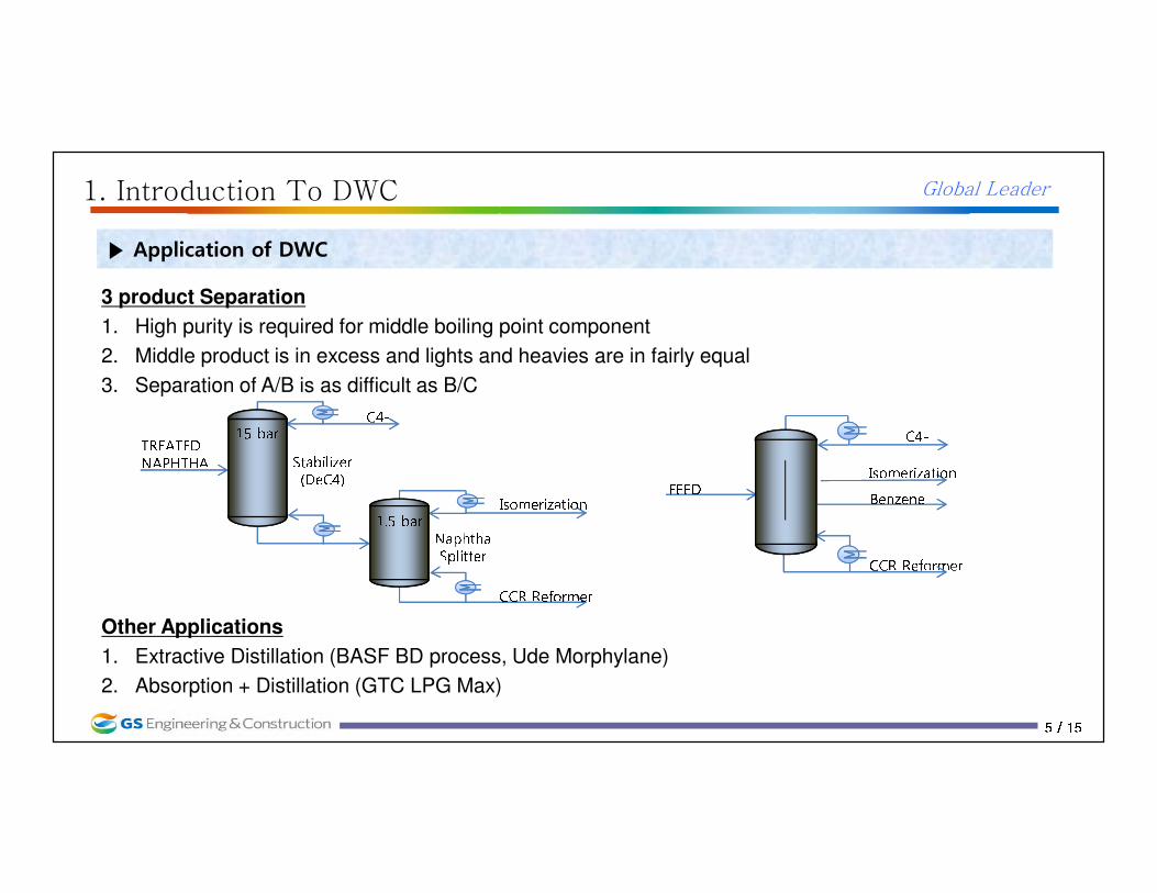
▶ Design Variables in Conventional Column
1520253035
17 18 19 20 21 22 23 24 25 26 27 28 29 30 31 32 33 34 35 36 37 38 39 40
1.No. of stages
2.Feed Location
3.Draw Location
2. Feed location 3. Side Draw location
1. No of Stages Duty
No. Stages

Global Leader
7777 / 15/ 15/ 15/ 15
2. DWC simulation
▶ Design Variables in DWC- DWC structure
6. Main Lin
8. Main Lout(Liquid split ratio)
7. Main Vout(Vapor split ratio)
5. Main Vin
3. Feed location
4. Side Draw location
2. Prefractionator Tray No.
1. Main columnTray No.
1.No. of stages in main column
2.No. of stages in prefractionator
3.Feed location of prefractionator
4.Side draw location
5.Feed location of main column vapor in
6.Feed location of main column liquid in
7.Main column vapor out rate
8.Main column liquid out rate

Global Leader
8888 / 15/ 15/ 15/ 15
2. DWC simulation
▶ Vapor & Liquid Split in DWC
Liquid out Vapor out
Duty
Liquid out Vapor out
Duty
Optimal operating regions at a certain vapor & Liquid Split
The range and stable optimal regions depend on the feed composition and DWC structure
Graphics from Chem. Eng. “Study of structural characteristics of a dividing wall column using the sloppy distillation arrangement by
Moonyong LEE (Yongnam Univ.)

Global Leader
9999 / 15/ 15/ 15/ 15
2. DWC simulation
▶ Design Variables in DWC – Interaction No. of trays No. of trays No. of trays No. of trays at each at each at each at each sectionsectionsectionsection Liquid splitLiquid splitLiquid splitLiquid splitVapor SplitVapor SplitVapor SplitVapor SplitReboilerReboilerReboilerReboiler DutyDutyDutyDuty
Condenser Condenser Condenser Condenser DutyDutyDutyDuty
An easy and powerful design procedure of DWC is required
Global Leader
10101010 / 15/ 15/ 15/ 15
3. B-Split
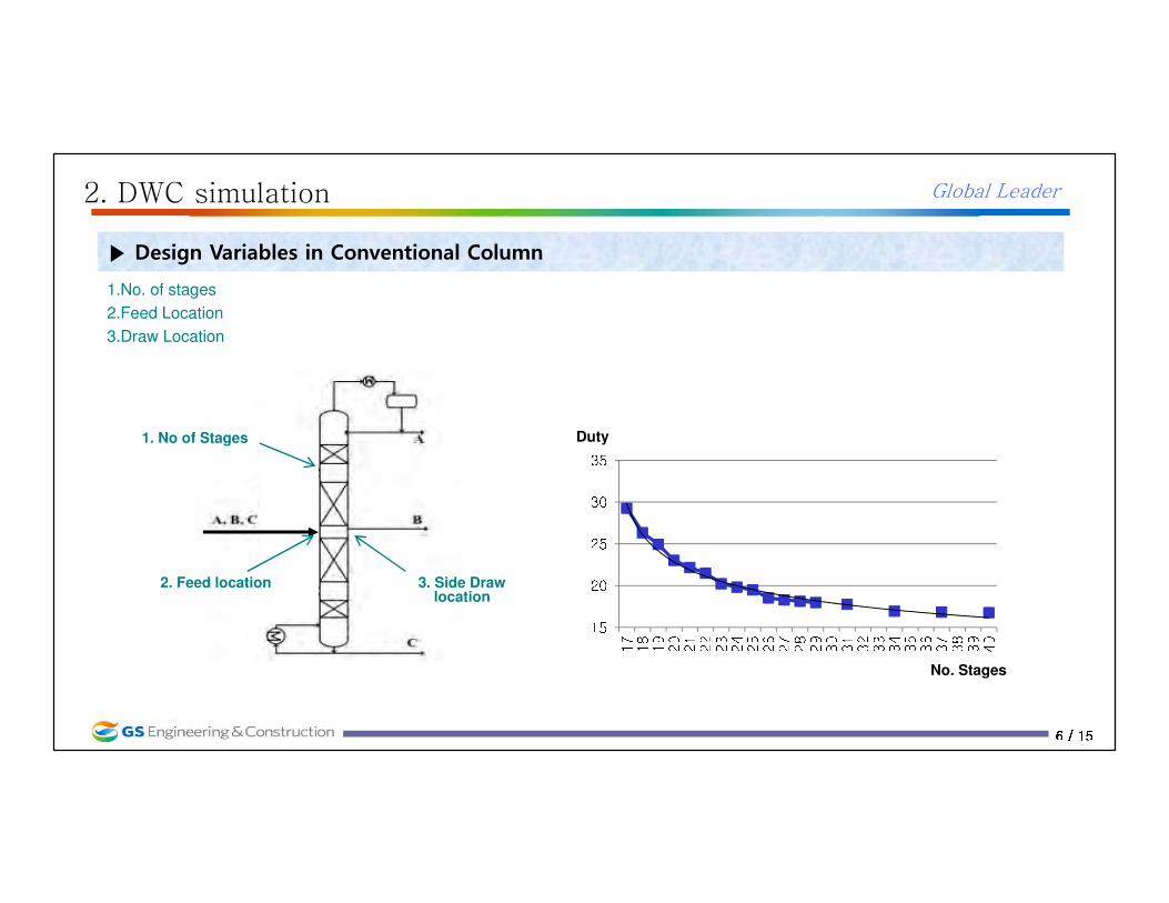
▶ B – Split (β) ; DefinitionThe fraction of component B that goes to the top of pre-fractionator out of total B flow
feed
After pre-fractionator
Final Product
Btop
Bbtm
Trying to find an optimal B-Split
Global Leader
11111111 / 15/ 15/ 15/ 15
3. B-Split
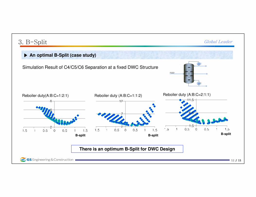
▶ An optimal B-Split (case study)
Simulation Result of C4/C5/C6 Separation at a fixed DWC Structure
2468
-1.5 -1 -0.5 0 0.5 1 1.5Reboiler duty(A:B:C=1:2:1)
2712
-1.5 -1 -0.5 0 0.5 1 1.5Reboiler duty (A:B:C=1:1:2)
1.56.511.5-1.5 -1 -0.5 0 0.5 1 1.5Reboiler duty (A:B:C=2:1:1)
There is an optimum B-Split for DWC Design
B-split B-split B-split
Global Leader
12121212 / 15/ 15/ 15/ 15
3. B-Split
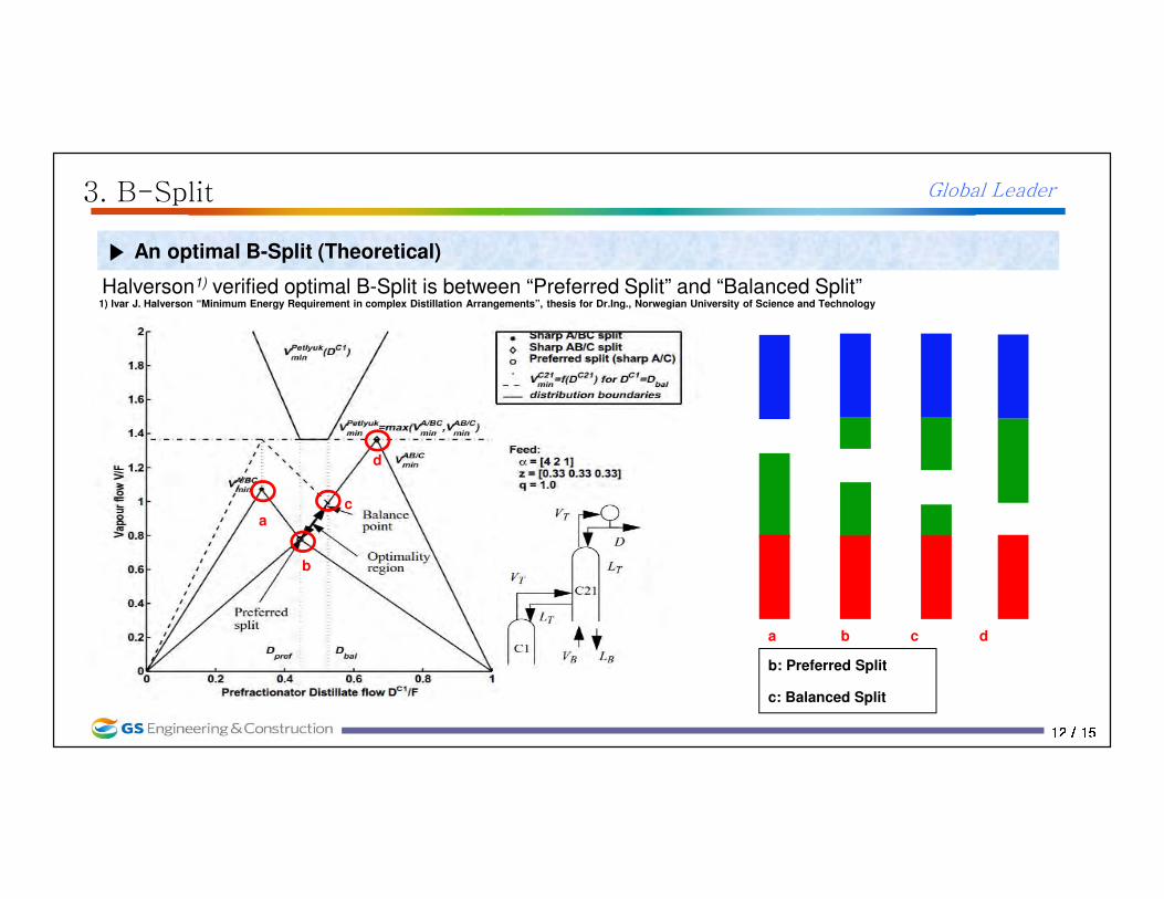
▶ An optimal B-Split (Theoretical)
Halverson1) verified optimal B-Split is between “Preferred Split” and “Balanced Split”
a b c d
b: Preferred Split
c: Balanced Split
a
b
c
d
1) Ivar J. Halverson “Minimum Energy Requirement in complex Distillation Arrangements”, thesis for Dr.Ing., Norwegian University of Science and Technology

Global Leader
13131313 / 15/ 15/ 15/ 15
3. B-Split
▶ An optimal B-Split (Theoretical)
The graph of Preferred / Balanced Split vs. ESI (ease of separability index, αAB/αBC)
00.10.20.30.40.50.60.70.80.910.5 0.7 0.9 1.1 1.3 1.500.10.20.30.40.50.60.70.80.91
0.5 0.7 0.9 1.1 1.3 1.5 00.10.20.30.40.50.60.70.80.910.5 0.7 0.9 1.1 1.3 1.5
Preferred splitBalanced splitInitial splitA:B:C=1:3:1 A:B:C=3:1:1 A:B:C=1:1:3
ESI
B-split
B/C cut hard
ESI increase
More B/C to bottom Large duty for Main-frac
Preferred Split dec. Blanced Split inc.
Global Leader
14141414 / 15/ 15/ 15/ 15
4. Design Procedure
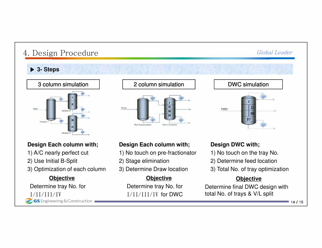
▶ 3- Steps
3 column simulation3 column simulation 2 column simulation2 column simulation DWC simulationDWC simulation
Design Each column with;
1) A/C nearly perfect cut
2) Use Initial B-Split
3) Optimization of each column
Design Each column with;
1) No touch on pre-fractionator
2) Stage elimination
3) Determine Draw location
Design DWC with;
1) No touch on the tray No.
2) Determine feed location
3) Total No. of tray optimization
Objective
Determine tray No. for
I/II/III/IV
Objective
Determine tray No. for
I/II/III/IV for DWC
Objective
Determine final DWC design with total No. of trays & V/L split
Global Leader
15151515 / 15/ 15/ 15/ 15
4. Design Procedure
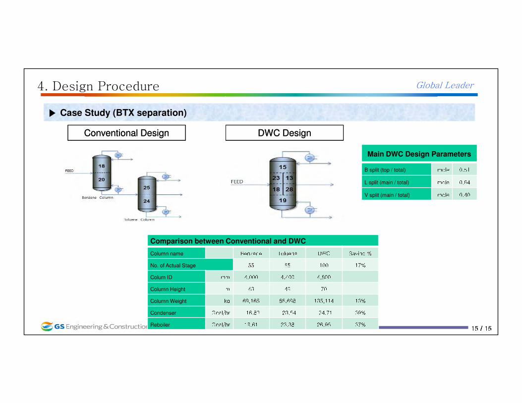
▶ Case Study (BTX separation)
Main DWC Design Parameters
B split (top / total) mole 0.51 L split (main / total) mole 0.64 V split (main / total) mole 0.40
Comparison between Conventional and DWC
Column name Benzene Toluene DWC Saving %No. of Actual Stage 55 65 100 17%Colum ID mm 4,000 4,400 4,800 Column Height m 43 49 70Column Weight kg 69,165 86,698 135,114 13%Condenser Gcal/hr -16.83 -23.54 -24.71 39%Reboiler Gcal/hr 19.61 23.38 26.95 37%
DWC DesignDWC DesignConventional DesignConventional Design

Global Leader
16161616 / 15/ 15/ 15/ 15