
PRACTICAL APPLICATION OF MULTIPLE PULSE IN AIR … · PRACTICAL APPLICATION OF MULTIPLE PULSE IN...
6
PRACTICAL APPLICATION OF MULTIPLE PULSE IN AIR (MPIA) LIDAR IN LARGE-AREA SURVEYS R. B. Roth a, *, J. Thompson b a Leica Geosystems, 13 Park Drive, Westford, MA 01886, USA – [email protected] b Northwest Group, Suite 212, 5438 – 11 th Street NE, Calgary, Alberta, Canada T2E 7E9 – [email protected] Commission I, WG I/2 KEY WORDS: LIDAR, Surveying, Technology, Acquisition, Calibration, Accuracy, Project ABSTRACT: Multiple Pulses in Air Technology, or MPiA, is a new technology allowing airborne LIDAR systems to be used at higher pulse rates than previously possible. By allowing the airborne LIDAR system to fire a second laser pulse prior to receipt of the previous pulse’s reflection, the pulse rate at any given altitude can be effectively doubled. Getting past the limitations imposed by the speed of light and conventional single-pulse-in-air LIDAR technology allows the airborne LIDAR system to achieve the desired point density at twice the coverage rate or, conversely, for twice the point density to be achieved at conventional coverage rates. Though announced publicly in 2006, it was not until well into 2007 that commercially-available MPiA-equipped systems were fielded. The technology can now be considered “mainstream”, and is actively being used on a variety of airborne LIDAR data acquisition projects. This study will present an overview of MPiA technology in the context of a large area survey project in Alberta, Canada. In addition to the consideration of MPiA technology in this project, implications on other facets of project organization will be presented. Overall results will be given, proving the ability of MPiA-equipped systems to achieve a nominal 2:1 productivity increase over that of conventional systems * Corresponding author. 1. INTRODUCTION 1.1 Introduction to Multiple Pulses in Air (MPiA) Technology Multiple Pulses in Air Technology, or MPiA, is a new technology allowing airborne LIDAR systems to be used at higher pulse rates than previously possible. By allowing the airborne LIDAR system to fire a second laser pulse prior to receipt of the previous pulse’s reflection, the pulse rate at any given flying height can be effectively doubled. Getting past the limitations imposed by the speed of light and conventional single-pulse-in-air LIDAR technology allows the airborne LIDAR system to achieve the desired point density to be achieved at twice the conventional coverage rate or, conversely, for twice the point density to be achieved at conventional coverage rates. Though announced publicly in 2006, it was not until well into 2007 that commercially available MPiA- equipped systems were fielded. The technology can now be considered “mainstream”, and is actively being used on a variety of airborne LIDAR data acquisition projects. Although the application of MPiA technology at very low altitudes can be limited by maximum achievable laser pulse rates, the use of this technology at higher altitudes presents few limitations. This makes the use of MPiA technology particularly applicable to large area surveying. Large area surveying is typically done for a variety of applications, including national mapping programs and regional flood zone or coastal mapping. In these applications, it is important to achieve a significant level of detail, with post spacing in the region of 2 meters. Although this level of detail can be readily achieved with conventional LIDAR systems, the typical flying heights used (2000 – 3000 m AGL) would normally result in laser pulse rates that limit maximum coverage rates. MPiA technology allows coverage rates to be effectively doubled thus lowering the data acquisition (i.e., flying) costs. This can be an important factor in the economic viability of large area mapping projects. In addition to simply increasing the possible laser pulse rates of the LIDAR system, MPiA also allows the user other benefits. Since the aircraft can fly substantially higher, the effects of terrain height variation on swath width are minimized, thus requiring less side overlap to assure complete area coverage. In addition, a narrower Field of View (FoV) can be used, resulting in better forest floor penetration in areas covered by vegetation. Finally, the generally higher flying altitudes used result in a less turbulent, more comfortable flight and less flight crew fatigue. This is particularly important given the high “duty cycle” of flying crews on large-area missions. In the example shown, multiple long-duration (up to 7 hours) missions are possible each day. 1.2 Operating Envelope of Single-Pulse versus MPiA Systems Figure 1 gives a comparison of the performance envelopes for a single-pulse versus MPiA versions of the ALS50-II. 183
Transcript of PRACTICAL APPLICATION OF MULTIPLE PULSE IN AIR … · PRACTICAL APPLICATION OF MULTIPLE PULSE IN...
PRACTICAL APPLICATION OF MULTIPLE PULSE IN AIR (MPIA) LIDAR IN LARGE-AREA SURVEYS
R. B. Roth a, *, J. Thompson b
a Leica Geosystems, 13 Park Drive, Westford, MA 01886, USA – [email protected]
b Northwest Group, Suite 212, 5438 – 11th Street NE, Calgary, Alberta, Canada T2E 7E9 – [email protected]
Commission I, WG I/2
KEY WORDS: LIDAR, Surveying, Technology, Acquisition, Calibration, Accuracy, Project ABSTRACT: Multiple Pulses in Air Technology, or MPiA, is a new technology allowing airborne LIDAR systems to be used at higher pulse rates than previously possible. By allowing the airborne LIDAR system to fire a second laser pulse prior to receipt of the previous pulse’s reflection, the pulse rate at any given altitude can be effectively doubled. Getting past the limitations imposed by the speed of light and conventional single-pulse-in-air LIDAR technology allows the airborne LIDAR system to achieve the desired point density at twice the coverage rate or, conversely, for twice the point density to be achieved at conventional coverage rates. Though announced publicly in 2006, it was not until well into 2007 that commercially-available MPiA-equipped systems were fielded. The technology can now be considered “mainstream”, and is actively being used on a variety of airborne LIDAR data acquisition projects. This study will present an overview of MPiA technology in the context of a large area survey project in Alberta, Canada. In addition to the consideration of MPiA technology in this project, implications on other facets of project organization will be presented. Overall results will be given, proving the ability of MPiA-equipped systems to achieve a nominal 2:1 productivity increase over that of conventional systems
* Corresponding author.
1. INTRODUCTION
1.1 Introduction to Multiple Pulses in Air (MPiA) Technology
Multiple Pulses in Air Technology, or MPiA, is a new technology allowing airborne LIDAR systems to be used at higher pulse rates than previously possible. By allowing the airborne LIDAR system to fire a second laser pulse prior to receipt of the previous pulse’s reflection, the pulse rate at any given flying height can be effectively doubled. Getting past the limitations imposed by the speed of light and conventional single-pulse-in-air LIDAR technology allows the airborne LIDAR system to achieve the desired point density to be achieved at twice the conventional coverage rate or, conversely, for twice the point density to be achieved at conventional coverage rates. Though announced publicly in 2006, it was not until well into 2007 that commercially available MPiA-equipped systems were fielded. The technology can now be considered “mainstream”, and is actively being used on a variety of airborne LIDAR data acquisition projects. Although the application of MPiA technology at very low altitudes can be limited by maximum achievable laser pulse rates, the use of this technology at higher altitudes presents few limitations. This makes the use of MPiA technology particularly applicable to large area surveying. Large area surveying is typically done for a variety of applications, including national mapping programs and regional flood zone or coastal mapping. In these applications, it is important to achieve a significant level of detail, with post spacing in the region of 2 meters. Although this level of detail can be readily
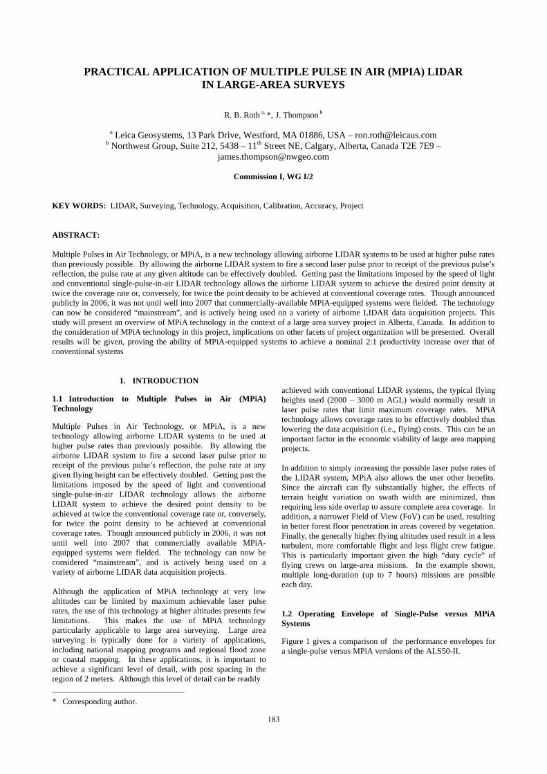
achieved with conventional LIDAR systems, the typical flying heights used (2000 – 3000 m AGL) would normally result in laser pulse rates that limit maximum coverage rates. MPiA technology allows coverage rates to be effectively doubled thus lowering the data acquisition (i.e., flying) costs. This can be an important factor in the economic viability of large area mapping projects. In addition to simply increasing the possible laser pulse rates of the LIDAR system, MPiA also allows the user other benefits. Since the aircraft can fly substantially higher, the effects of terrain height variation on swath width are minimized, thus requiring less side overlap to assure complete area coverage. In addition, a narrower Field of View (FoV) can be used, resulting in better forest floor penetration in areas covered by vegetation. Finally, the generally higher flying altitudes used result in a less turbulent, more comfortable flight and less flight crew fatigue. This is particularly important given the high “duty cycle” of flying crews on large-area missions. In the example shown, multiple long-duration (up to 7 hours) missions are possible each day. 1.2 Operating Envelope of Single-Pulse versus MPiA Systems
Figure 1 gives a comparison of the performance envelopes for a single-pulse versus MPiA versions of the ALS50-II.
183

Figure 1. Comparison of conventional and MPiA operating envelope
2. PROJECT OVERVIEW
2.1 Project Location and Coverage Area
The project area consists of the entire Alberta province (~640000 km2), along with adjacent parts of British Columbia and Saskatchewan provinces. In total, the project area encompasses 750,000 km2. In addition to its sheer size, this project is distinguished by the fact that it is largely an “on-spec” project. Although some portions of the collected data was flown for specific clients, the remainder of the area is being flown without a specific client. A small portion of the data (~5%) had been previously flown and processed, and was therefore available from archive. The progress toward acquisition and processing of the remaining portions of this project are the subject of this investigation. 2.2 Project Duration
The project was started in May 2007 and is multi-year in nature, owing to its large size and restrictions in operating season. The data being collected covers both mountainous and prairie areas. For the mountainous areas, the flying season is limited to July and August in order to maximize the area uncovered by snowpack. Despite this limited flying season, some areas flown are permanently covered with snow and/or ice. For prairie areas, the flying season is substantially longer, starting in May. Permanent seasonal snow cover begins in October, at which point operations are suspended for the year. In each flying season, roughly one-third of the project is completed. 260 flights were completed in 2007. 200 of these flights were made using a single aircraft. The remaining 60 flights were made using aircraft and LIDAR systems from a subcontractor. These additional flight were made primarily to ensure a full supply of data to be processed over the non-flying season.
2.3 Project Specifications
Since the project is being done primarily “on spec”, there is some freedom to determine specifications for point density and accuracy. However, the specifications selected are fairly typical for medium or large-area jobs. The objective is to create a bare-earth DEM with a point spacing of 1 to 1.5 meters. Accuracy objectives are RMS values of 20 cm Z and 50 cm XY. 2.4 Aircraft Used
The aircraft used for the majority of the data acquisition was a Cessna 335. This is an unpressurized aircraft with twin piston engines and propeller propulsion. The was no optical window through which the LIDAR system had to fire, and thus refraction corrections for an air/glass/air interface was not needed. Other similar aircraft were also used at points in the project.
Figure 2. Cessna 335 survey aircraft 2.5 LIDAR System Used
Figure 3. Leica Geosystems ALS50-II LIDAR system The LIDAR system employed was a Leica geosystems ALS50-II, and was equipped for MPiA operation. The ALS50-II system is capable of pulse rates up to 150 kHz in both conventional and MPiA modes. In MPiA mode, the system
184
The International Archives of the Photogrammetry, Remote Sensing and Spatial Information Sciences. Vol. XXXVII. Part B1. Beijing 2008

achieves 150 kHz pulse rates at up to approximately 1200 m AGL. However, in order to minimize the effect of terrain reducing swath covered, it was decided to fly at a slightly higher altitude, where the maximum pulse rate was typically 110-120 kHz. Although designed to collect up to 4 returns from each outbound laser pulse (first, second, third and last), the nature of the vegetation cover typically resulted in a single or double return only. 2.6 Mission Planning and System Settings
Mission planning was accomplished using Leica Geosystems FPES software with an a priori DEM input. The use of an a priori DEM helps to minimize the number of flight lines by allowing adjustment of flight elevations and/or direction and reducing the total terrain relief over any given flight line. In the prairie areas, where there is little terrain relief and reliable DEM information is available, planning could be fully automated. In some areas, the accuracy or resolution of the available a priori DEM data was in question. This was particularly true in more mountainous regions. Therefore, in many cases, some manual planning was done to allow grouping of flight lines together a one altitude, while adjacent groups of flight lines could be flown at a higher or lower altitude as needed. These “altitude groups” could then be submitted for automated flight line layout. This process also minimizes the number of different altitudes to be flown in each flight, saving the time required for altitude changes. Furthermore, some of the mountainous areas had to be flown from altitudes as high as 19,000 feet AMSL. The twin-engine piston-propeller aircraft used on this project can take a full hour to reach that altitude. The planning process used minimizes the number of high-altitude flights required and also helps to minimize the duration for which the flight crew would require supplemental oxygen. 2.6.1 Typical flight line layout: The remote nature of much of the area flown dictated a unique approach to project layout. The overall project is broken down into 80 km x 80 km blocks. Each block consists of a number of parallel 80-km-long flight lines, oriented in a north-south direction. In some unusual cases flight lines might be oriented parallel to geographic features, but most are oriented north-south. An east-west cross strip is flown over the north and south ends of the block, extending slightly beyond the ends and into the adjacent blocks. In this manner, a single cross-strip comes into contact with up to 6 blocks, thus minimizing the number of cross strips required. Within each cross strip, there are a minimum of two ground control points. These ground control points are used both as an accuracy check as well as for setting the XYZ reference. In addition to the flight lines and cross strips, a “cloverleaf” boresight flight pattern was performed at the beginning of each flight. This additional data is used later for confirmation and/or adjustment of IMU boresight calibration. 2.6.2 Typical flight profile and LIDAR system settings: Typical missions were flown at 1600 m AGL with a speed over ground of approximately 130 knots (~67 m/s). This results in a typical “on-line” duration of 20 minutes to cover the 80 km line length. It is important to note that 20 minutes is the maximum
straight-line flight duration recommended to prevent accumulation of IMU drift beyond the specified accuracy of the GNSS/IMU subsystem. The Leica IPAS CUS6 IMU was chosen for all LIDAR systems used on this project in order to minimize drift and maximize accuracy. At this nominal flying height, turbulence was typically minimal over the prairie areas. However, turbulence was sometimes excessive over the more mountainous areas. At the higher absolute elevations required over mountainous terrain (which are near the service ceiling of the aircraft), aircraft handling is less precise. This resulted in postponement of some acquisition areas pending better flight conditions. System settings varied slightly across the project area, depending on the amount of terrain relief within the flight lines. In general, flight plans put the system near the lower end of the MPiA operating envelope for a particular pulse rate. This was done to maximize accuracy. Typical pulse rates were between 110 and 120 kHz, though sometimes as low as 100 kHz if large terrain relief was expected. Field of view was typically planned for 35-40 degrees, maximizing canopy penetration in any forested areas. Typical side overlap was 20% of the raw swath width, and all systems used employed active roll compensation. This provided more than adequate overlap, given the typical 30-40 meter accuracy with which the pilot can navigate the planned flight line, and leaving additional margin for aircraft yaw due to crosswinds. The system settings and resulting net swath width under varying terrain relief is shown below in Table 1 for both MPiA operation as well as conventional 1PiA operation. In all cases, liberal allowances for flight navigation tolerances were used; +/-50 m in the vertical direction and +/-70 meters in the horizontal direction. A maximum FOV of 40 degrees was specified in order to maximize foliage penetration and minimize height error at the FOV edge. Flying heights were adjusted in each mode (MPiA or 1PiA) so that the same point spacing could be obtained in both operating modes. At the planned flying heights for the project, the maximum pulse rate attainable in 1PiA mode is not vastly lower than that of MPiA operation. However, the real advantage is apparent as the amount of terrain relief within any flight line increases. As terrain elevation under the aircraft increases over parts of the flight line, the net swath width (after removing allowances for navigation error) decreases. The effect is greater when using 1PiA operation. Furthermore, the effect is magnified as the amount of terrain relief increases. Therefore, it is clear that MPiA offers quantifiable advantages even beyond the theoretical 2:1 advantage provided under zero-terrain-relief conditions.
Terrain relief (m) None 300 600
Mode MPiA 1PiA MPiA 1PiA MPiA 1PiAPulse rate (kHz) 120 89.3 120 89.3 120 89.3
Flight height (m above terrain)
1600 1100 1300-1600
800-1100
1000-1600
500-1100
185
The International Archives of the Photogrammetry, Remote Sensing and Spatial Information Sciences. Vol. XXXVII. Part B1. Beijing 2008

Side overlap required
20 27 38 53 56 79
Net swath width 927 583 721 376 514 170
MPiA advantage
1.59:1 1.92:1 3.02:1
Table 1. Comparison of planned swath width for MPiA and
conventional operation with varying terrain relief.
3. DATA PROCESSING SOFTWARE
3.1 Initial Processing
Initial processing of the LIDAR data accomplished using standard software. Standard tools included Waypoint GrafNav for DGPS processing, Leica Geosystems IPAS Pro for GNSS/IMU processing, and Leica Geosystems ALS Post Processor for point cloud generation.
3.2 Boresight Calibration
Boresight calibration was performed using a combination of standard and in-house software. Factory boresight calibration is set using Leica Geosystems Attune software. Additional boresight adjustments were made if needed. Any additional adjustment were made using project data from one flight and either Terrasolid’s TerraMatch software or other in-house software tools in order to maximize accuracy. 3.3 Filtering for Bare-Earth Model
Filtering prior to final “delivery” to archive is performed using Terrasolid’s TerraScan and TerraModeler software. All point clouds are processed to delete redundant data in the overlap regions. All points are classified (e.g., bare earth vegetation, etc.) and all remaining points after redundant data removal are retained for archiving. No thinning of point data is performed prior to final storage. In that manner, end customers can order data products at a variety of spatial resolutions and still be able to access embedded classification information. 3.4 Finished Product Storage
After completion of filtering and final data QC, all data is ultimately backed up to tape devices.
4. LOGISTICS AND STAFFING REQUIREMENTS
Logistics and staffing are both important considerations on a project of this magnitude. Equipment availability, personnel skill sets and utilization, processing workflow and, of course, weather are all significant constraints 4.1 Mission Planning Staffing
Mission planning consumes roughly 1.5 full-time-equivalent staff members. Although this sounds significant, it is in line with typical estimates of 10-20% of total job labor.
4.2 Data Acquisition Staffing
For each aircraft, two flight crews were used. Each flight crew consisted of a pilot and a system operator. Off-duty flight crew were used for placement and monitoring of GNSS base stations, as well as for copying mission data to backup/transport media. Consistent GNSS base station monitoring was considered essential, due to the remote locations required. Although equipped with large battery supplies capable of up to 4 days’ operation, base stations were usually monitored continuously by the off-duty flight crew. In addition to the 2 flight crew travelling with each aircraft, an aircraft mechanic was constantly on-call. Aircraft inspections, which occurred every 50 flight hours, might take place at nearly any day of the week or time of day, depending on weather conditions. Inspections would occur every 5 days if good weather prevailed, and the inspection would essentially take the place of one flight. Most inspections were performed at the field location. This staffing level was adequate to support a continuous duty cycle of two 5-6 hour missions per day, providing acceptable weather conditions. Mission durations as long as 7 hours were attained and. in some instances, 3 mission per day were accommodated. It should be noted that this “burst mode” could only be accommodated for a very short time without introducing excessive fatigue in the flight crew. Though most of the acquisition was performed with a single aircraft, additional aircraft were deployed late in the season to maximize data collection for off-season processing. Similar staffing was employed for each additional aircraft. 4.3 Data Logistics
At the conclusion of each flight, mission data from the ALS50-II removable hard drive was copies to two independent stand-alone 1 TB USB or Firewire drives. Each of these drives could accommodate mission data from several flights. Once several days’ data was accumulated on these derives, one drive would be sent to the processing center. The other would be retained at the job site. Due to the remote location of some of the acquisition areas, express mail services were not always available. As an alternative small-package delivery services by bus transport lines was sometimes used. A maximum time interval of 3-4 days between data shipments was targeted. When a backup drive was received at the processing center, data would be immediately checked for proper GNSS/IMU and point cloud processing. This process runs approximately in a 1:1 ratio with flight time given a single workstation. As soon as point cloud processing was complete and initial data QC performed, the field crew was notified and the duplicate backup drive retained at the field site was then freed to be overwritten with new data. It is interesting to note that incoming data QC was initially performed using point clouds that were subsampled 2:1 prior to evaluation. However, the additional processing time required for non-subsampled point cloud processing was not too significant and provided much better insight into the overall quality of the incoming data. Therefore, the incoming inspection process was modified to include 1:1 processing of all data.
186
The International Archives of the Photogrammetry, Remote Sensing and Spatial Information Sciences. Vol. XXXVII. Part B1. Beijing 2008

4.4 Additional Equipment Used
In addition to the aircraft and installed systems, a number of additional equipment items were needed. 4.4.1 Transfer/backup dives used were 1 TB “Firewire” drives, and an minimum of 5 were required for each aircraft (one drive being filled with the current 4-6 mission, one backup of the previous 4-6 mission retained in the field pending data verification at the processing center, one in transit to the processing center, one at the processing center being verified and one in transit back to the field). 4.4.2 GNSS base stations, of which at least five were required. One used at the airport field base, plus a minimum of two for each east-west cross-strip at the northern and southern ends of the block. 4.4.3 Large-capacity batteries for GNSS base stations were used. Each battery could power a base station for up to 4 days. 4.4.4 Four-wheel-drive trucks, of which two were used. Many of the GNSS base station locations were located on unimproved rural by-ways, where use of a traditional rental car would be impractical. In addition, the trucks were equipped with “camper caps” that could be used as a sleeping area in the event the ground crew monitoring the GNSS base station needed to stay overnight.
5. CHARACTERISTICS OF RESULTING DATA
To date, approximately 3.29 x 10¹¹ points have been acquired to date, assuming only a single return from each outgoing laswer pulse. Of those, approximately 2.64 x 10¹¹ points have been retain for archiving. The following section summarizes various attributes of the acquired data. 5.1 Comparison with 1PiA Data
As mentioned previously, some of the data within the project area was collected at an earlier date using a conventional (i.e., 1PiA) system. Data from the MPiA system used in this project provide accuracies at least as good as those from the previous 1PiA system. 5.2 Comparison with Advertized System Specifications
Data collections are consistently meeting the targeted RMSE accuracy specifications of 20 cm Z and 50 cm XY. Typical estimated accuracies for ALS50-II systems, expressed as standard deviation, are 13 cm Z and 20 cm XY, assuming 10 cm GNSS error. 10-15 cm GNSS error was typically achieved by using a minimum of 5 base stations for each flight, one located at the airport and 2 on each operating cross strip at the job site. Factoring in the slightly higher GNSS error than used on the ALS50-II accuracy estimates, the remaining difference between ALS50-II estimated accuracy and the achieved accuracy is accounted for by the fact that final accuracy achieved is quoted in RMSE terms, as opposed to standard deviation. It should be noted that, though some of the data is collected at northern latitudes, there was not noticeable degradation in GPS accuracy due to this. No particular effort was made to optimize
flying times to maximize GNSS satellite coverage. Instead, flights were performed any time there was good weather. Despite this, there was minimal, if any, problem with poor PDOP. 5.3 Forest Floor Penetration
The project areas consisted of both prairie and forested mountain areas. The nature of the northern Canadian forest is such that there was little, if any need to “over-collect” in order to meet the desired ground point density targets. Adequate space between tree stems and minimal undergrowth meant that nearly all laser shots resulted in a return from the forest floor. 5.4 Relative Match Between Adjacent Flight Lines
In areas of rugged terrain, the target point density was low enough compared to the terrain feature size such that any slight mismatch between data from adjacent flightlines was not discernable. However, the prairie areas where there is little terrain relief, small elevation difference where adjacent flight lines meet are more readily noticed. Even elevation differences that were well within both predicted and specification values were easily observed in prairie area. For these areas, additional effort was put into refining boresight calibration so that any difference could be kept small enough to be unnoticeable. In these areas, it was not uncommon to refine calibration values until any height were less than 3-4 cm.
6. CONCLUSIONS
From the extensive use of 3 MPiA-equipped ALS50-II systems on the project, it can be concluded that MPiA technology is well suited to improving the acquisition rate of LIDAR point cloud data. It is clearly demonstrated that significant reductions in data acquisition time can be realized. It can also be concluded that the use of MPiA technology does not sacrifice data quality. Data obtained using MPiA technology compared favourably with data acquired over similar terrain and operating conditions with conventional single-pulse-in-air systems. Finally, the use of MPiA technology provides additional benefits that are not directly quantifiable including reduced flight crew fatigue. This is mainly due to reduced turbulence at the higher flying heights allowed when using MPiA. From the foregoing it is readily seen that MPiA technology fully realizes predicted benefits and is capable of delivering and even exceeding the theoretical 2:1 benefit in terms of data acquisition cost over attempting to acquire similar density data using non-MPiA technology, especially were there is any significant terrain relief. It can therefore be recommended as the preferred alternative to conventional single-pulse-in-air systems. From the standpoint of acquiring massive terrain data sets at medium spatial resolution, it can be concluded that flight planning, mission execution and data processing logistics all benefit from some level of optimization. Given adequate weather conditions, very large projects of this type are feasible, even with a single aircraft, although there are some additional benefits of multiple aircraft operations. In particular, multiple aircraft could be flying in the same or adjacent project block,
187
The International Archives of the Photogrammetry, Remote Sensing and Spatial Information Sciences. Vol. XXXVII. Part B1. Beijing 2008

The International Archives of the Photogrammetry, Remote Sensing and Spatial Information Sciences. Vol. XXXVII. Part B1. Beijing 2008
minimizing the total time needed for monitoring GNSS base stations in comparison to area covered. From the standpoint of potential for reflights, the size of the project area relative to the mobilization distance was small. In the event of any need to re-fly, the aircraft was usually still at the same base when any need was determine, and any additional flight lines could be readily added before mobilizing to a new base.
ACKNOWLEDGEMENTS
The authors wish to acknowledge the support of staff members at both Leica Geosystems and Northwest Group in the production of this paper. In particular the authors thank Russell Carr at Northwest Group for the effort in relating the various challenges in the subject project from planning, acquisition and processing perspectives.
188