Practical Application of a New Advanced Dynamic Based Hull ...
16
@ THE SOCIETY OF NAVAL ARCHITECTS AND MARINE ENGINEERS ~ ,m! 7{.,. o @ “1 and 3 THE SHIP STRUCTURE COMMITTEE ,“, .“$* Paper presented at the Ship Structures Symposum ’93 Sheraton National Hotel, Arlington,Virginia, November lE-17,1993 Practical Application of a New Advanced Dynamic Based Hull Structural Strength Design and Evaluation Criteria Todd W. Grovel, William G. Coulter2 ‘Technical Coordinator, American Bureau of Shipping, New York 2Principal Engineer, American Bureau of Shipping, New York Abstract A presentation is offered summarizing the technical fea- tures of a new dynamic based hull structural strength design and evaluation criteria for tankers developed by the American Bureau Shipping as the most significant update of the traditional classification strength criteria in decades. The paper focuses on how this new criteria, utilizing engineering fwst principles, can be applied in a practical day-to-day design setting. This is in the form of a dedi- cated software applications system for use on IBM-comp- atible personal computers and engineering workstations. The procedures involved in applying the software system to the design and evaluation of tanker structures is dis- cussed. Introduction The criteria typically employed by industry to design the hull structure of large commercial vessels are those pub- lished by the major international classification societies. Representatively, criteria, as offered by the American Bureau of Shipping, are essentially semi-empirical, expe- rience-based standards reflecting over 130 years of suc- cessful practical application [1]. Over the past 20 years the indushy has experienced dramatic changes in vessel design, particularly in terms of vessel size and arrange- ment, optimization of structure based on computer aided design, and material usage. Many of these design features fall outside the experience base of the existing strength criteria. As a result the traditional primary structural failure mode of concern, yielding, has expanded to include the modes of buckling and fatigue, which may control the design. Hence, buckling and fatigue can no longer be assumed to be accounted for via implied safety margins of the existing critmia. As there is no consistent and rational basis for extending the existing criteria into these new areas a new basis must be established. In recognition of these concerns, in 1990 ABS undertook a major research and development effo~ as part of its overall RULES 2000 initiative, to completely recast its hull structure criteria based on a first principles engineer- ing approach. This work has been facilitated by many of the new methods and tools that have also been developed over the last 20 years, and is based in large part on the design by analysis approach that has been of increasing interest in recent years. Once ddveloped these criteria have berm tested, calibrated and verified against the wealth of experience embodied in the traditional strength criteria. ABS has now completed the first phase of this proj6ct by issuing to industry for trial use its strength and fatigue guides for tankers [2,3] as the ABS SafeHull System for Tankers. The theoretical development of the criteria em- bodied in the SafeHull System has been well documented in recent publications to industry [4]. Having developed the technical basis for such criteria the focus now must be on how such criteria can effectively be applied in a prac- tical design situation. Because of the relative complexity of the criteria to that of the traditional criteria a software system has been specially developed to complement and facilitate the application of the criteria. This paper will center on the procedures involved in the day-to-day use of these new criteria through the software applications sys- tem. By way of introduction a summary of the criteria itself will frost be offered along with an example of the validity of the criteria. Strength Criteria Basic Principles The objective of this R&D effort has been to develop a new engineering fmt principles based hull structural strength criteria. This criteria has been designed to allow a more realistic, comprehensive, technically consistent, integrated and yet flexible approach to quantify the loads K-1
Transcript of Practical Application of a New Advanced Dynamic Based Hull ...
@
THE SOCIETY OF NAVAL ARCHITECTS AND MARINE ENGINEERS~,m!7{.,.
o@ “1 and
3 THE SHIP STRUCTURE COMMITTEE,“,.“$*
Paper presentedat the Ship StructuresSymposum ’93
Sheraton NationalHotel,Arlington,Virginia, November lE-17,1993
Practical Application of a New Advanced DynamicBased Hull Structural Strength Design and EvaluationCriteriaTodd W. Grovel, William G. Coulter2
‘Technical Coordinator, American Bureau of Shipping, New York2Principal Engineer, American Bureau of Shipping, New York
Abstract
A presentation is offered summarizing the technical fea-tures of a new dynamic based hull structural strengthdesign and evaluation criteria for tankers developed by theAmerican Bureau Shipping as the most significant update
of the traditional classification strength criteria in decades.The paper focuses on how this new criteria, utilizingengineering fwst principles, can be applied in a practical
day-to-day design setting. This is in the form of a dedi-cated software applications system for use on IBM-comp-
atible personal computers and engineering workstations.The procedures involved in applying the software systemto the design and evaluation of tanker structures is dis-cussed.
Introduction
The criteria typically employed by industry to design the
hull structure of large commercial vessels are those pub-lished by the major international classification societies.Representatively, criteria, as offered by the AmericanBureau of Shipping, are essentially semi-empirical, expe-rience-based standards reflecting over 130 years of suc-cessful practical application [1]. Over the past 20 yearsthe indushy has experienced dramatic changes in vesseldesign, particularly in terms of vessel size and arrange-ment, optimization of structure based on computer aideddesign, and material usage. Many of these design features
fall outside the experience base of the existing strengthcriteria. As a result the traditional primary structuralfailure mode of concern, yielding, has expanded to includethe modes of buckling and fatigue, which may control thedesign. Hence, buckling and fatigue can no longer beassumed to be accounted for via implied safety margins
of the existing critmia. As there is no consistent andrational basis for extending the existing criteria into thesenew areas a new basis must be established.
In recognition of these concerns, in 1990 ABS undertooka major research and development effo~ as part of its
overall RULES 2000 initiative, to completely recast itshull structure criteria based on a first principles engineer-ing approach. This work has been facilitated by many ofthe new methods and tools that have also been developedover the last 20 years, and is based in large part on thedesign by analysis approach that has been of increasinginterest in recent years. Once ddveloped these criteria
have berm tested, calibrated and verified against thewealth of experience embodied in the traditional strength
criteria.
ABS has now completed the first phase of this proj6ct byissuing to industry for trial use its strength and fatigueguides for tankers [2,3] as the ABS SafeHull System for
Tankers. The theoretical development of the criteria em-
bodied in the SafeHull System has been well documentedin recent publications to industry [4]. Having developedthe technical basis for such criteria the focus now must be
on how such criteria can effectively be applied in a prac-tical design situation. Because of the relative complexityof the criteria to that of the traditional criteria a softwaresystem has been specially developed to complement and
facilitate the application of the criteria. This paper willcenter on the procedures involved in the day-to-day use ofthese new criteria through the software applications sys-tem. By way of introduction a summary of the criteriaitself will frost be offered along with an example of thevalidity of the criteria.
Strength Criteria
Basic PrinciplesTheobjective of this R&D effort has been to develop anew engineering fmt principles based hull structuralstrength criteria. This criteria has been designed to allowa more realistic, comprehensive, technically consistent,integrated and yet flexible approach to quantify the loads
K-1
Ship Structures Symposium ’93
and stresses in a ship’s structure as well as the require-
ments of the structure to resist these loads. The criteriahas also been formulated and fully documented to easilyaccommodate future research findings and adjustments
warranted from actual service experience. The short-termgoal has been to provide industry with a design tool as wellas one for assessing structures throughout their service
lives. In the long-term the fkxibility of the current deter-ministic format provides an intermediate step and sound
foundation towards a reliability-based strength criteria.
A few of the more novel features of the criteria am:
Dynamic Loads: The fundamental basis to
the new criteria is the determination of realis-tic dynamic loads including hydrodynamic, in-ertial and sloshing loads. Additionally, the
criteria provides the unique solution to the re-alistic combination of these component loadsin a complete and integrated manner.
Net Ship: Traditionally, hull strength hasbeen assessed based on the uncorroded condi-
tion of the structure. The impact of corrosionon strength over the life of the vessel has beenignored. IrI the new criteria the nominal corro-
sion margins expected over the life of the ves-sel are removed and the strength requirementsare based on this reduced condition. Thus,the criteria helps ensure safer structures
throughout a vessel’s life, not just in its as-built condition.
MkJE: Through extensivewlication of de-tailed spectral fatigue analyses on ships ABShas established a thorough experience basefrom which criteria have been derived to al-low accurate screening of the fatigue life chm-acteristics of structural details. Based on thecumulative damagm theory in conjunctionwith appropriate S-N data this is an original
and unique tool for the industry.
Intemated Approach: The new criteria em-ploy an approach to assure the systematic andintegrated development of a vessel designthrough determination of the realistic dy-namic loads, establishment of minimum in-itial scantlings (strength criteria) forindividual stmctural elements, followed by athorough assmsment of the primary failuremodes of concern: yielding, buckling and fa-tigue (stmngtb assessment) for the overallstructural system. The loads are all fully inte-grated into both the strength criteria and as-sessment. All necessary information, data
and equations are provided both in the
strength and fatigue guides as well as in thesoftware application system. Explicit guide-lines ,are provided for all necessary analysesto ensure consistent application.
As noted in the previous item the criteria is essentiallydivided into three key elements: generation of realisticloads, strength criteria, and strength assessment. These
areas are briefly elaborated upon in the following.
Load Criteria
The load components considered in the new criteria are:
1) global hull-girder loads including both
static still water and wave induced dynamicloads,
2) static and dynamic components of theinternal pressures of liquid in the tanks, and
3) external hydrodynamic pressure and its
distribution over the ship length and girth.
The magnitude of each load component is defined as the
“nominal design load”. In order to obtain the combinedload effects, a set of design load cases is derived, wherethe dominant load component and simultaneously occur-ring load components are combined in the appropriate
manner. See Section 3 of [2].
Strength Criteria
The strength criteria is to allow the derivation of initialscantlings during the preliminary design phase in terms of
both local and hull girder requirements established inconjunction with the specified load and failure criteria.This differs from traditional criteria in that much greateremphasis is placed on the treatment of local structure inaddition to overall hull-girder strength. This is to accountfor the increased use of high tensile steels and thus therelated concerns of local buckling and fatigue comparedto tlm traditional use and characteristics of mild steel.
The initial design scantling selection criteria are applica-ble to double hull tankers ranging from 190 to 500 metersin length having a length-to-beam ratio not less than 5 anda breadth-to-depth ratio equal to or less than 2.5. Thecriteria development focus has been on double hull con-figurations considering the ongoing industry trend in thisarea. However, explicit guidance for single hull configu-rations is also included along with basic guidance onmid-deck configurations. The criteria include require-ments for plating, longitudinal and other stiffeners, longi-tudinal girders and floors in the double bottom, and the
main supporting members.
K-2
Grove and Coulter on Design Criteria
The initial scantlings obtained using the strength criteria
are considered initial design minimum values. Theseneed to be verified via a detailed stress analysis andassessment as described below. See Section 4 of [2] for
details of the initial scantling strength criteria.
Strength AssessmentAs noted above the initial scantlings must be vmified via
detailed stress analyses and assessment of the sh-ucture asan integrated system. The stress analyses provide not onlyan added degree of assurance of the vessel’s safety but theanalyses also provide useful insight that may help to
monitor the condition of the as-built structure. Thestrength assessment of the structure covers the failuremodes of yielding, buckling and fatigue. Additionally, theultimate hull-girder stiength in the intact and assumeddarnaged condition is also considered. The results of these
stress analyses and strength assessment serve as a basis forthe judicious and rationalized increase in scantlings abovethe initial minimum values as needed.
The stiess analyses are carried out using finite elementanalyses (EEA) for both 3-D global and 2-D fine-mesh
models. Detailed modeling guidelines have been devel-oped to maintain a uniform level of quality in the analysesthat is required to arrive at a meaningful comparison ofresults. Much of the FEA has been automated through the
software system. This will be further described below.
Details of the failure criteria and strength assessment can
be found in Section 5 of [2].
Comparison with Existing Designs andCriteria
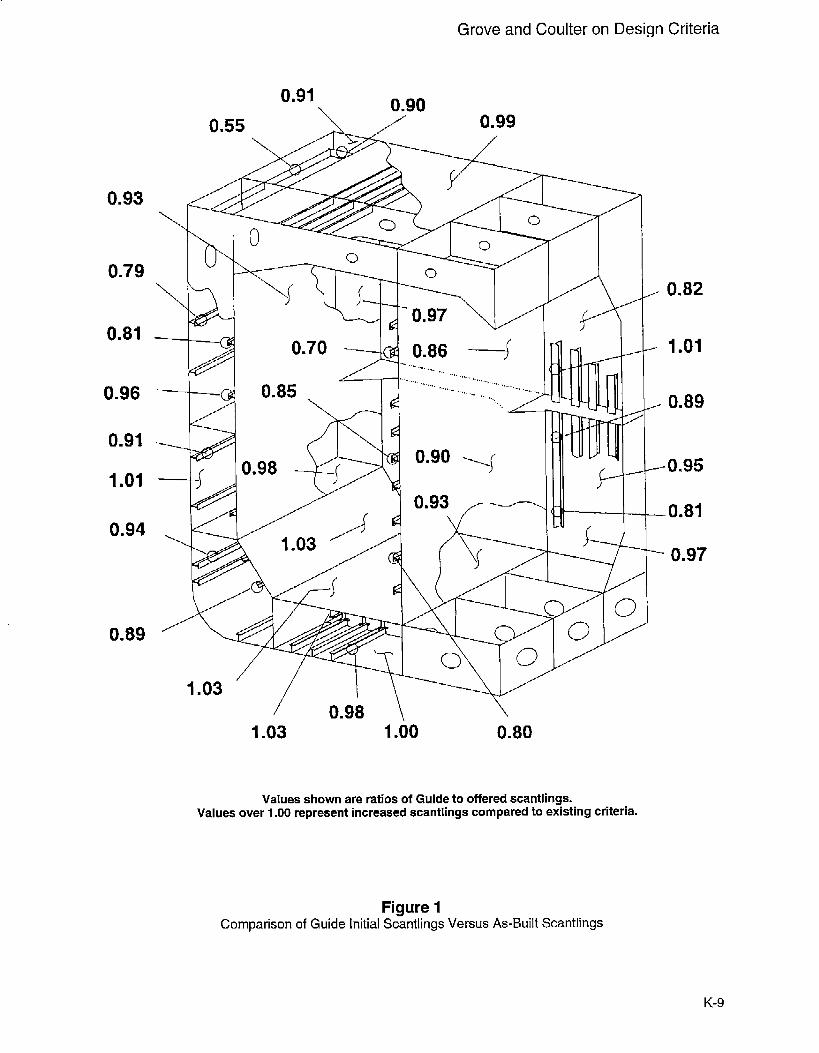
In introducing any new stiengtb criteria it is important todemonstrate that the criteria has been appropriately cali-brated and verified against current criteria and practica. Adetailed comparison is offered in [4]. In summary, acomparison of tlm initial minimum scantlings of the new
criteria versus those of the m-built vessel are illustrated inFigure 1. The comparison shows that Guide values areessentially comparable to those required by the present1993 ABS Rules. The variations reflect the redistributionof material in the hull girder as found in applying the newcriteria. Some of these values would be expected toincrease as a result of the subsequent stiength assessment.A similar comparison of fatigue lives is offered in [5].
necessary component of the overall ABS SafeHull System
because of the first principles format of the new criteria.As the criteria is no longer in the traditional form of
simplified formulas and tables the software is needed tomake the criteria a practical tool for use in day-to-daydesign situations. While this is a significant departurefrom conventional application of classification criteria it
is in keeping with modern technology commonly in useby the industry worldwide.
The design loads, for example, am given as distributedfunctions over the hull structure in terms of the locationof interest as well as th~ principal geometry of the vessel.Similarly the formulas used to assess strength involvemany more variables than the old format.
The software system is available to industry as part of the
overall SafeHull System. This provides greater consis-tency in the application of the criteria and will greatlyfacilitate both the design and.evaluation processes. Both
of these attibutes should also enhance the safety of thestructure by eliminating the guess work related to judgingthe quality and consistency of the software and analysis
methods used by the designer in the design and evaluationprocesses.
Software Platforms
The software is designed to run on IBM personal comput-ers (PC’s) and compatibles running version 5.0 or higher
of the industry standard DOS operating system. PC’susing 386-based CPU’s are considered the minimum ac-ceptable platform for the development of initial scantlings
(See PhaseA analysis, below). A math coprocessor is alsooptional for this phase of the analysis. For the Phase Banalysis, which involves performance of finite elementanalyses, a 486-based PC is recommended and a mathcoprocessor is required.
The PC was selected as the development platform for a
number of reasons, among which is the ready worldwideavailability and affordability of these machines. The PC
platform also allows many of the advancements in per-sonal computer technology to be utilized in enhancing thecapabilities of the software. Recognizing that the engi-neering workstation is also a standard design tool, ABS iscurrently working on the migration of the SafeHull Sys-tem applications software to the workstation envirorunent.
In addition to the criteria itself [2] a comprehensive over- System Architectureview of the new strength criteria is presented in [4]. The software applications system is comprised of a suite
of interactive programs for the design and analysis of
Description of Software tanker structures. In addition to the engineering analysis
Applications System programs, routines are also provided expressly for thestreamlining of the voluminous input data required for the
The software applications system that has been developed detailed analytical modeling of ‘a vessel. - With user-
in parallel with the Strength and Fatigue Guides is a friendliness a key issue in the development, these input
K-3
Ship Structures Symposium ’93
data preparation programs have been developed to makeextensive use of interactive on+.creen color VGA graph-ics, graphical HPGL format reports, and active mouse andcursor key control among others. The goal of this inputapproach has been to make the data input as straightfor-
ward and intuitive as possible, minimizing the need forcompanion user’s manuals. This emphasis on streamlin-
ing of the input is in large part due to the issue of produc-tivity. With the computational ability of today’s PC’s theactual calculation time for many of the engineering mod-
ules can be quite short. Thus, most of the time for theanalysis is found to be associated with the human inter-
face. Therefore, every effort has been placed on reducingthis time.
The system features a pull-down menu system that is
organized to lead the user through the analyses in a sys-tematic step-by-step manner. The options availabla in thetop level menu include capabilities for the user to setup aspecific system configuration for their site. The input and
output files are created automatically based on the projectand vessel names specified by the user. This internal file
management helps enhance the integrity of the vessel+pe-cific files, which is important considering the number of
data files can grow quite large.
To enhance the flexibility of the system a more traditional“batch” type input scheme using a text editor is alsobuilt-in as an alternative option for users more comfort-able with this input approach.
Integration
The software system can be installed and utilized as a fully
integrated, stand-alone system. This includes all of thedata- preparation and analyses for determination of theinitial scantlings as well as the analyses for the strengthassessment. The one exception is the execution of theFEA calculation itself. The FEA solver provided with theSafeHull System is the PC-based GIFTS FEA package.While this is a separate system the execution of the FEAcalculation can be called directly from the SafeHull Sys-tem software, streamlining the overall flow of the analy-ses.
Alternatively, the software system has been structured ina modular fashion with the intention of permitting usersto integrate the SafeHull System software into their exist-
ing applications. This is primarily in terms of FEA sys-tems that a designer may already have establishedin-house. ABS can provide appropriate neutral data filesfor modeling, loading of the structure and post-processingto assist users in integrating the SafeHull System softwarewith their FEA system. The format of these files has been
generated to be consistent with requirements for NAS-TRAN. Other FEA systems can be used with the SafeHull
system. However, the important common element in any
SafeHull related ,analysis is the use of ABS specified
loads. These loads are required to ensure the accuracy ofanalysis results.
Methods of Applications
The primary use of the software, and the new criteria ingeneral, focuses on tl-m design and evaluation of newtanker designs. Therefore, the system can be applied by
designers in developing the initial scantlings for a tankerthrough the full strength assessment of the hull structure
leading into the detailed design stage. Subsequent to thisstage the design is submitted for ABS review for classifi-cation. ABS employs the SafeHull System criteria and
software to perform an evaluation of the design. The factthat the designer has this tool available that ABS will alsoemploy in the review process obviously helps the designerin knowing early in the process whether there could be
problems in compliance of the structure with class require-ments. This prior knowledge will also aid in stiearnliningthe class review process by minimizing the number of
amendments required to the submitted design.
In addition to the application of the software system to thedesign and evaluation of new designs, ABS is continuing
to develop the services employing the system for theassessment of existing vessels. The criteria will enable asound technical basis for the assessment of existing tanker
structures and provide users with detailed information
such as critical areas that should be monitored in the hull.
For system description purposes the application of the
system to new vessel design and evaluation is focussed on
in the following sections.
Flow of Analysis
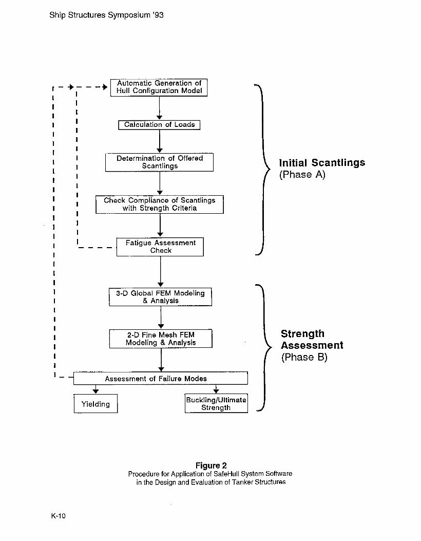
The overall flow of the SafeHull System applicationssoftware is shown in Figure 2. The analysis can be dividedinto two major phases: Phase A - determination of initial
minimum scantlings and assessment of fatigue, and PhaseB - strength assessment of the primary failure modes ofconcern. These two phases are structured to be followedin an iterative manner. Phase A is performed and repeatedas necessary to develop initial scantlings that meet therequirements of the criteria. Once these requirements aresatisfied the strength assessment is performed iterative yuntil the overall structural system meets the failure criteriafor yielding, buckling and ultimate sbength specified inth~ Stiengt.h Guide,
The flow of the system has been developed to follow that
of the classic design spiral for ships. While each designerhas their own unique design process, it is felt that the
details of the system described below will dernonshate itsutility in individual situations.
K-4
Grove and Coulter on Design Criteria
Analysis Procedure: Phase A - Initial$cantlings
This phase of the SafeHull System software allows per.formance of the calculations necessmy to determine thehull structural scantlings required to satisfy Section 3-“Load Criteria”, Section 4- “Strength Criteria”, and thefirst level of strength assessment, fatigue, from Section 5
- “Strength Assessment” of the Strength Guide [2]. Thescantlings from Phase A are considered “initial” scant-lings as they must still pass the strength assessment of
Phase B, described below. It is estimated that experiencedusers of the software can perform a complete iteration of
the Phase A analysis in a 2 to 3 day period. With the ease
of use and speed of this analysis it is expected that thisanalysis will be a very useful tool during bidding andpreliminary design phases.
The following describes the individual steps of the analy-
sis for Phase A as shown in Figure 2.
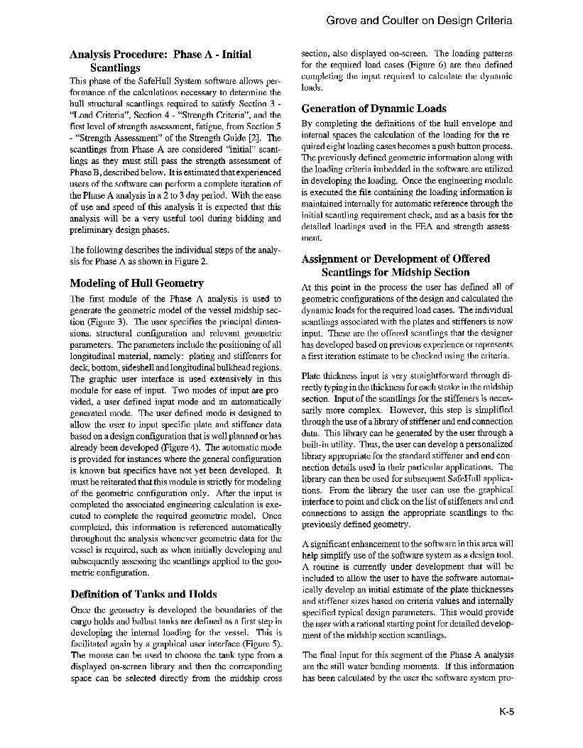
Modeling of Hull Geometry
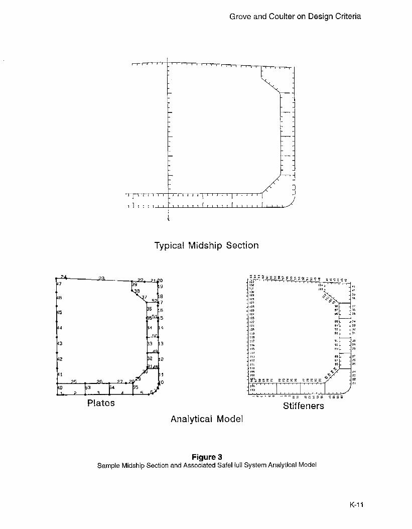
The fust module of the Phase A analysis is used togenerate the geometric model of the vessel midship sec-
tion (Figure 3). The user specifies the principal dimen-sions, structural configuration and relevant geometric
parameters. The parameters include the positioning of alllongitudinal material, namely: plating and stiffeners for
deck, bottom, sidw.hell and longitudinal bulkhead regions.The graphic user interface is used extensivdy in thismodule for ease of input. Two modes of input are pro-vided, a user defined input mode and an automaticallygenerated mode. The user defined mode is designed to
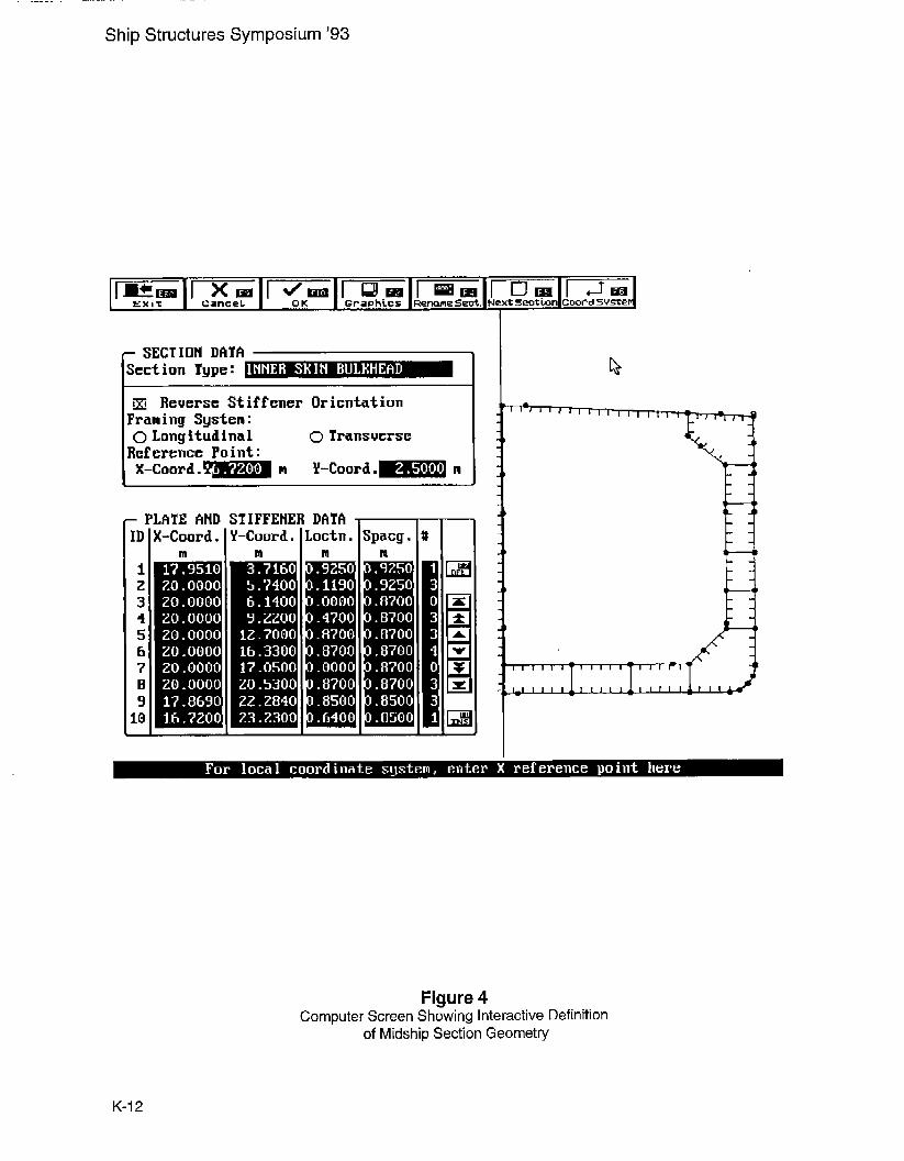
allow the user to input specific plate and stiffener databased on a design configuration that is well planned or hasalready been developed (Figure 4). The automatic mode
is provided for instances where the general configurationis known but specifics have not yet been developed. Itmust be reiterated that this module is strictly for modelingof the geometric configuration only. After the input iscompleted the associated engineering calculation is exe-cuted to complete the required geometric model. Oncecompleted, this information is referenced automaticallythroughout the analysis whenever geometric data for thevessel is required, such as when initially developing andsubsequently assessing the scantlings applied to the geo-metric configuration.
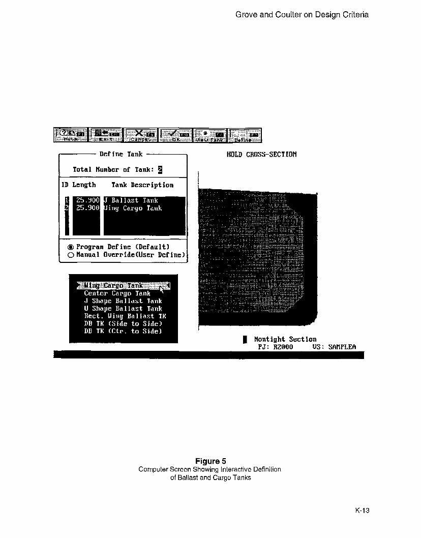
Definition of Tanks and Holds
Once the geometry is developed tlm boundaries of thecargo holds and ballast tanks are defined as a first stap indeveloping the internal loading for th~ vessel. This isfacilitated again by a graphical user interface (Figure 5).The mouse can be used to choose the tank type from a
displayed on-screen library and then the correspondingspace can be selected directly from the midship cross
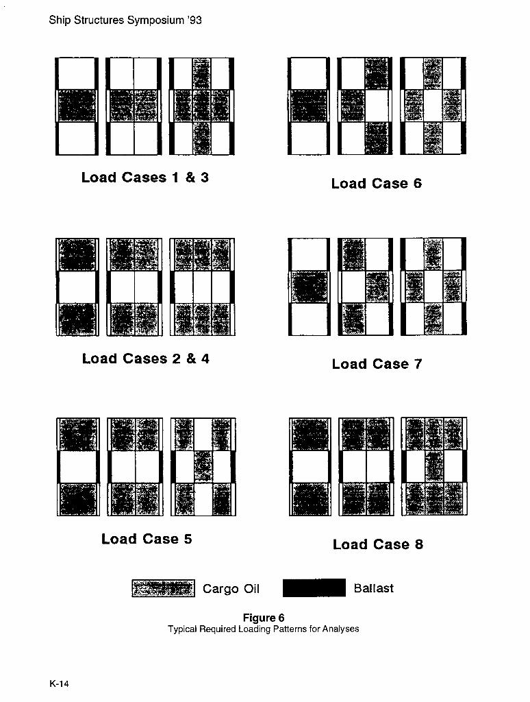
section, also displayed on-screen. The loading patterns
for the required load cases (Figure 6) are then definedcompleting the input required to calculate the dynamicloads.
Generation of Dynamic LoadsBy completing the definitions of the hull envelope andinternal spaces the calculation of the loading for the re-quired eight loading cases becomes a push button process.
The previously defined geometric information along withthe loading criteria imbedded in the software are utilizedin developing the loading. Once the engineering module
is executed the file containing the loading information ismaintained internally for automatic reference through theinitial scantling requirement check, and as a basis for thedetailed loadings used in the FEA and strength assess-ment.
Assignment or Development of OfferedScantlings for Midship Section
At this point in the process the user has defined all ofgeometric configurations of the design and calculated thedynamic loads for the required load cases. The individual
scantlings associated with the plates and stiffeners is nowinput. These are the offered scantlings that the designer
has developed based on previous experience or representsa first iteration estimate to be checked using the criteria.
Plate thickness input is very straightforward through di-rectly typing in the thickness for each strake in the midship
section. Input of the scantlings for the stiffeners is neces-sarily more complex. However, this step is simplifiedthrough the use of a library of stiffener and end connection
data. This library can be generated by the user through abuilt-in utility. Thus, the user can develop a personalizedlibrary appropriate for the standard stiffener and end con-nection details used in their particular applications. The
library can then be used for subsequent SafeHull applica-tions. From the library the user can use the graphicalinterfacE to point and click on the list of stiffeners and endconnections to assign the appropriate scantlings to thepreviously defined geometry.
A significant enhancement to the software in this area will
help simplify use of the software system as a design tool.A routine is currently under development that will beincluded to allow the user to have the software automat-ically develop an initial estimate of the plate thicknessesand stiffener sizes based on criteria values and internally
specified typical design parameters. This would providethe user with a rational starting point for detailed develop-ment of the midship section scantlings.
The final input for this segment of the Phase A analysisare the still water bending moments. If this information
has been calculated by the user the software system pro-
K-5
Ship Structures Symposium ’93
vides for this information to be input and employed in the
analysis. If the values for the hogging and sagging still
water bending moments are unknown the amdysis willemploy appropriate criteria-defined default values.
An interim step provided to the user at this juncture in theanalysis is the calculation of the offered section modulus
properties. This is another push button operation uponcompletion of the above input. In addition to the necessity
of this information for the overall SafeHull analysis this
calculation is seen as a simplified section modulus calcu-
lator for general use beyond the direct application of thesoftware for SafeHull purposes.
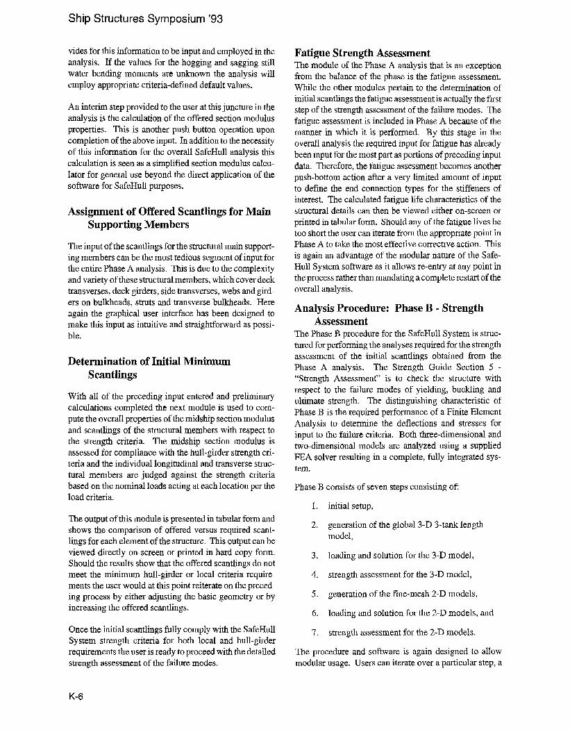
Assignment of Offered Scantlings for MainSupporting Members
The input of the scantlings for the structural main support.
ing members can be the most tedious segment of input forthe entire Phase A analysis. This is due to the complexityand variety of these structural members, which cover decktransverses, deck girders, side transverses, webs and gird-
ers on bulkheads, struts and transverse bulkheads. Here
again the graphical user interfacE has been designed tomake this input as intuitive and straightforward as possi-
ble.
Determination of Initial MinimumScantlings
With all of the preceding input entered and preliminarycalculations completed the next module is used to com-
pute the overall properties of the midship section modulus
and scantlings of the structural members with respect tothe strength criteria. The midship section modulus is
assessed for compliance with the hull-girder strength cri-teria and the individual longitudinal and transverse struc-tural members are judged against the strength criteriabased on the nominal loads acting at each location per the
load criteria.
The output of this module is presented in tabular form and
shows the comparison of offered versus required scant-lings for each element of the structure. This output can be
viewed directly on-screen or printed in hard copy form.Should the results show that the offered scantlings do not
meet the minimum hull-girder or local criteria require-ments the user would at this point reiterate on the preced-ing process by either adjusting the basic geometry or byincreasing the offered scantlings.
Once the initial scantlings fully comply with the SafeHullSystem strength criteria for both local and hull-girder
requirements the user is ready to proceed with the detailedstrength assessment of the failure modes.
Fatigue Strength AssessmentThemodule of the Phase A analysis that is an exceptionfrom the balance of the phase is the fatigu~ assessment.
While the other modules pertain to the determination ofinitial scantlings the fatigue assessment is actually the firststep of the strength assessment of the failure modes. Thefatigue assessment is included in Phase A because of themanner in which it is performed. By this stage in the
overall analysis the required input for fatigue has alreadybeen input for the most part as portions of preceding input
data. Therefore, the fatigue assessment becomes anotherpush-bottom action after a very limited amount of input
to define the end connection types for the stiffeners ofinterest. The calculated fatigue life characteristics of the
structural details can then be viewed either on-screen orprinted in tabular form. Should any of the fatigue lives betoo short the user can iterate from the appropriate point inPhase A to take the most effective corrective action. This
is again an advantage of the modular nature of the Safe-
Hull System software as it allows re-entry at any point inthe process rather than mandating a complete restart of theoverall analysis.
Analysis Procedure: Phase B - StrengthAssessment
ThePhaw B procedure for the SafeHull System is struc-
tured for performing the analyses required for the strength
assessment of the initial scantlings obtained from thePhase A analysis. The Strength Guide Section 5 -
“Strength Assessment” is to check the structure with
respect to the failure modes of yielding, buckling and
ultimate strength. The distinguishing characteristic ofPhase B is the required performance of a Finite Element
Analysis to determine the deflections and srrmses forinput to the failure criteria. Both three-dimensional andtwo-dimensional models are analyzed using a supplied
FEA solver resulting in a complete, fully integrated sys-tem.
Phase B consists of sewm steps consisting ofi
1,
2.
3.
4.
5.
6.
7.
initial setup,
generation of the global 3-D 3-tank lengthmodel,
loading and solution for the 3-D model,
strength assessment for the 3-D model,
generation of the fine-mesh 2-D models,
loading and solution for the 2-D models, and
sk-ength assessment for the 2-D models.
The procedure and software is again designed to allow
modular usage. Users can iterate over a particuku step, a
K-6
Grove and Coulter on Design Criteria
group of steps or the entire Phase B process. To providea uniform and consistent method of analysis for thestrength assessment FEA detailed guidance is provided in
[6]. The precepts in this guidance are automated in thesoftware system to streamline the procedure and execu-tion time. It is estimated that experienced users of thesoftware can perform a complete iteration of the Phase B
analysis in a period on the order of 2 to 3 weeks. Thisanalysis is seen as an effective tool for use in contract anddetailed design phases.
The following provides an overview of the key elements
of the Phase B process as shown in Figure 2.
Initial SetupThe initial setup step is effectively the link between the
data generated in Phase A and the passage of the pertinentportions of this data to the analyses of Phase B. Thenecessary data is that needed to calculate loads accordingto the criteria. This includes principal dimmsions, web
frame spacing, tank descriptions and tank arrangements.This step is currently being streamlined with the objective
of making this link transparent to the user.
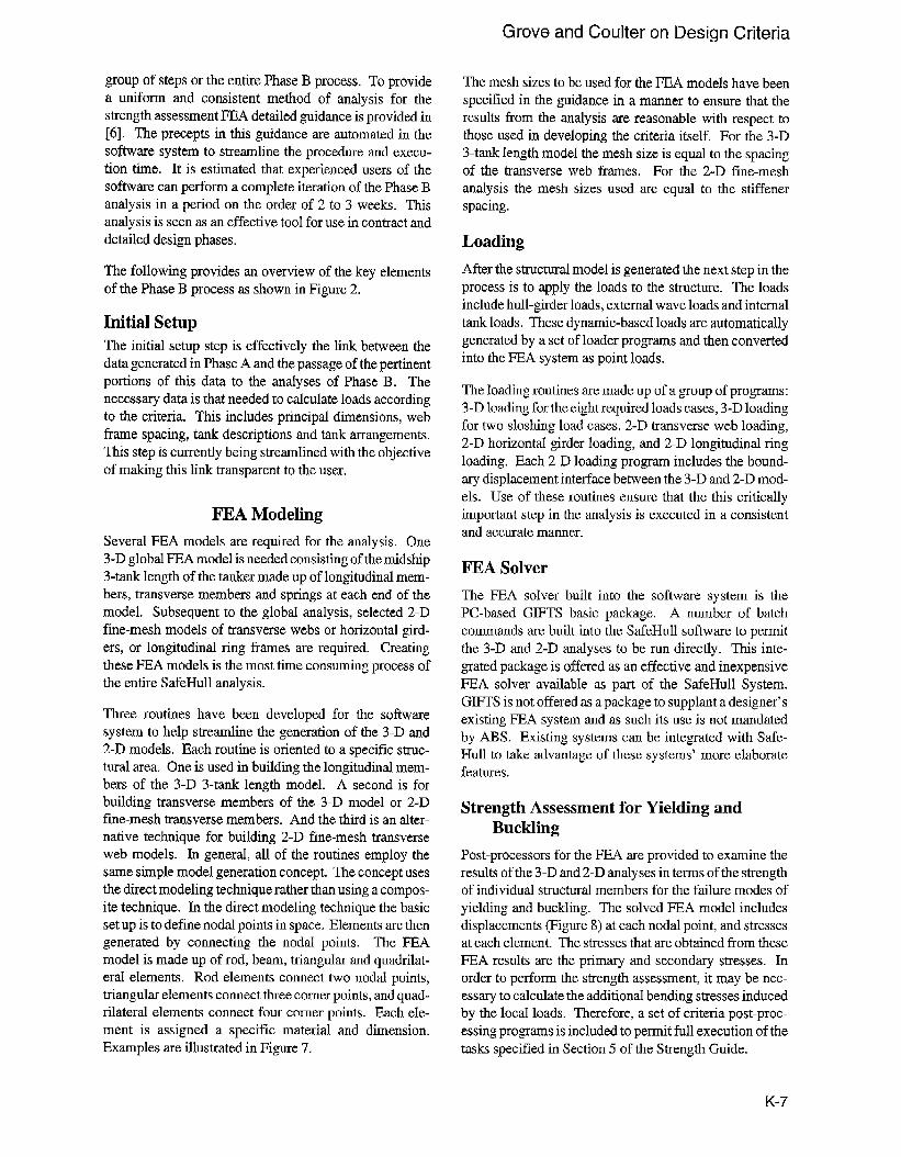
FEA Modeling
Several FEA models are required for the analysis. One3-D global FEA model is needed consisting of the midship3-tank length of the tanker made up of longitudinal mem-bers, transverse members and springs at each end of the
model. Subsequent to the global analysis, selected 2-Dfine-mesh models of transverse webs or horizontal gird-ers, or longitudinal ring fi-ames are required. Creating
these FEA models is the most time consuming process ofthe entire SafeHull analysis.
Three routines have been developed for the software
system to help streamline the generation of the 3-D and2-D models. Each routine is oriented to a specific struc-
tural area. One is used in building the longitudinal mem-bers of the 3-D 3-tank length model. A second is forbuilding transverse members of the 3-D model or 2-Dfine-mesh transverse members. And the third is an alter-native technique for building 2-D fine-mesh transverseweb models. In general, all of the routines employ the
same simple model generation concept. The concept uststhe direct modeling technique rather than using a compos-
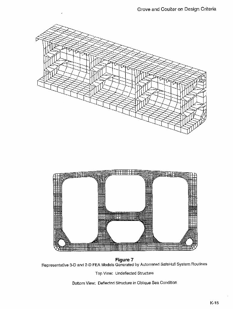
ite technique. In the direct modeling technique the basicset up is to define nodal points in space. Elements are thengenerated by connecting the nodal points. The FEAmodel is made up of rod, beam, triangular and quadrilat-eral elements. Rod elements connect two nodal points,triangular elements connect three corner points, and quad-rilateral elements connect four comer points. Each ele-ment is assigned a specific material and dimension.Examples are illustrated in Figure 7.
The mesh sizes to be used for the FEA models have beenspecified in the guidance in a manner to ensure that theresults from the analysis are reasonable with respect tothose used in developing the crite~ia itself. For the 3-D3-tank length model the mesh sizo is equal to the spacing
of the transverse web frames. For the 2--D fine-meshanalysis the mesh sizm used are equal to the stiffenerspacing.
Loading
After the structural model is generated the next step in theprocess is to apply the loads to the structure. The loadsinclude hull-girder loads, external wave loads and internal
tank loads. These dynamic-based loads are automaticallygenerated by a set of loader programs and then convertedinto the FEA system as point loads.
The loading routines are made up of a group of programs:
3-D loading for the eight required loads cases, 3-D loadingfor two sloshing load cases, 2-D transverse web loading,2-D horizontal girder loading, and 2-D longitudinal ring
loading. Each 2-D loading program includes the bound-ary displacement interface between the 3-D and 2-D mod-els. Use of these routines ensure that the this critically
important step in the analysis is executed in a consistentand accurate manner.
FEA Solver
The FEA solver built into the software system is thePC-based GIFTS basic package. A number of batch
comands are built into the SafeHull software to permitthe 3-D and 2-D analyses to be run directly. This inte-grated package is offered as an effective and inexpensive
FEA solver available as part of the SafeHull System.GIFTS is not offered as a package to supplant a designer’sexisting FEA syst~m and as such its use is not mandated
by ABS. Existing systems can be integrated with Safe-Hull to ta!-w advantage of these systems’ more elaborate
features.
Strength Assessment for Yielding andBuckling
Post-processors for the EEA are provided to examine the
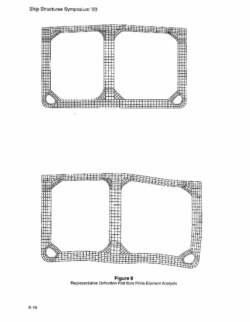
results of the 3-D and 2-D analyses in terms of the strengthof individual structural members for the failure modes ofyielding and buckling. The solved FEA model includesdisplacements (Figure 8) at each nodal point, and stressesat each element. The stresses that are obtained from theseFEA results are the primary and secondary simsses. Inorder to perform the strength assessment, it may be nec-Essary to calculate the additional bending stresses inducedby the local loads. Therefore, a set of criteria post-proc-essing programs is included to permit full execution of the
tasks specified in Section 5 of the Strength Guide.
KH7
Ship Structures Symposium ’93
The results of the strength assessment are presented in
tabular form for review to judge the viability of the scant-lings. If inadequacies are found at each step of the strengthassessment the process must be rep~ated to adjust th~structure and scantlings appropriately to meet the failure
criteria requirements specified in the Strength Guide.
Conclusion
ABS views the SafeHull System for Tankers as a signifi-
cant technological breakthrough relative to the rational,comprehensive, consistent and integrated nature of the
new strength criteria and supporting software system. Thesystem has been designed to be incorporated into theday-to-day design process of designers to allow them tomore thoroughly and rapidly assess a variety of designs.
Thus a design can be more completely developed resultingin more efficient production of the structure. Since thesoftware applications system will also be employed byABS in the review of designs for classification, structures
developed by designers using the SafeHull software canexpect virtually pre-approved scantlings, which will
streamline the classification review process. Using thenew first principles-based criteria more durable vessels
can be produced. Ones that have an improved margin ofsafety and more effective use of material. Steel weight isexpected to be nearly the same as that required by the
existing criteria, however, that steel will be more appro-priately distributed through the hull girder into the most
critically stressed areas. Identification and subsequentmonitoring of these critical areas will permit more effi-cient maintenance planning through the vessel’s life.
ABS is continuing to enhance the software system andcontinuing developments are ongoing for the overall Safe-Hull System. The SafeHull System for Bulk Carriers isscheduled to be released to industry in the near fiture.Follow-orI developments are also planned for otlmr major
vessel types such as containerships and gas carriers. Asthe current release for tankers is being offered to industryin a trial use mode comments and feedback from applica-tion of the system to practical situations is particulw
valuable and welcomed by AIM to ensure a useful tool for
industry.
Acknowledgment
Theauthors would like to thank the Ship Structures Corn.mittee and SNAME for inviting ABS to present this paper.We would also like to recognize the many engineers inABS who have contributed so much effort to the develop-ment of the new strength criteria over the last three yearsand also the engineers who have developed the softwareapplications system. We would particularly like to thank
Ping Liao for his contributions on the Phase B portion ofthis presentation. Additionally, we would like to thank theprojEct management for their support of and contributionsto this presentation, namely: Don Liu, John Conlon, Hsao
Chen and Faith Lee.
1.
2.
3.
4.
5.
6.
References
“Rules for Building and Classing Steel Vessels”,American Bureau of Shipping, 1993.
“Guide for Dynamic Based Design and Evaluation of
Tanker Structures”, American Bureau of Shipping,September 1993.
“Guide for Fatigue Strength Assessment of Tankers”,American Bureau of Shipping, September 1993.
Chen, H. H., Jan, H. Y., Conlon, J.F., Liu, D., “NewApproach for the Design and Evaluation of DoubleHull Tanker Structures”, Centennial Meeting of theSociety of Naval Architects and Marine Engineers,Septemb~r 1993.
Cordon, J.F., “The Role of Ship Design and Evalu-ation Criteria in Improving Hull Structural Safety”,International Conference on Tankers and Bulk Car-riers - The Way Ahead, 10-11 December 1992,
RINA, London, 1992.
“Guidance for the FinitE Element Analysis of TankerStructures for the ABS SafeHull System”, Ameri-can Bureau of Shipping, September 1993.
K-8
0.93
0.79
0.81
0.96
0.91
1.01
0.94
Grove and Coulter on Design Criteria
0.89
1.03 1.00 0.80
Values shown are ratios of Guide to offered scantlings.Values over 1.00 represent increased scantiings compared to existing criteria.
/ 0.82
# 1.01
, 0.89
-0.95
—--0.81
-0.97
Figure 1Comparison of Guide Initial Scantlings Versus As-Built Scantlings
K-9
Ship Structures Symposium ’93
I
I
I
I
I
I
1
I
I
I
I
1
I
1
‘1
I
I
I
I
1
I
1
1
1
I
I
I
I
I
[
I
I
1
I
I
I
I
I
I
1
I
I
1
I
I
I
I
-+--”+Automatic Generation of
r Hull Configuration Model
.TDetermination of Offered
Scantlings
+
?
Check Compliance of Scantlings
IFatigue Assessment----Check I
+
3-D Global FEM Modeling& Analysis
1
v
I_Assessment of Failure Modes 1
E&l&
Initial Scantlings(Phase A)
StrengthAssessment(Phase B)
Figure 2Procedure for Application of SafeHull System Software
in the Design and Evaluation of Tanker Structures
K-1 O
Grove and Coulter on Design Criteria
Typical Midship Section
Plates
Analytical Model
Stiffeners
Figure 3Sample Midship Section and Associated SafeHull System Analytical Model
K-1 1
Ship Structures Symposium ’93
EImlmlmllm[mlmExit CanoeL OK GPa phics ReMPW Scot. Next 5ect ion Coord 5V<te
-SECTION III+TASection Type: ~ : “1 h
~ Reverse Stiffener llrientutionFraming Systm:O Longitudinal O TrimsverseReference Point:X–Cored._ m Y-Coord._ m J
-PLRTE AND STIFFENER IMM ~
IX-Coord. Y-Coord.m PI
Figure 4Computer Screen Showing Interactive Definition
ofMidship Section Geometry
K-1 2
Grove and Coulter on Design Criteria
IJd ine Tnnk
Total Number of Tunk: ~
ID Length Tank Description
,1-
OFrogram Define [Default]~tlanual Oucrride[llserI)efincl
HOLD CllOSS-SECTItlti
!I
~ ticmtight SectionPJ: RZ@30 US: SMPLEfi
Figure 5ComputerScreen Showing Interactive Definition
of Ballast and Cargo Tanks
K-1 3
Ship Structures Symposium ’93
Load Cases 1 & 3 Load Case 6
Load Cases 2 & 4 Load Case 7
Load Case 5 Load Case 8
Cargo Oil - ‘allas’
Figure 6Typical Required Loading Patterns for Analyses
Grove and Coulter on Design Criteria
Figure 7Representative 3-D and 2HD FEA Models Generated by Automated SafeHull System Routines
Top View: Unreflected Structure
Bottom View: Deflected Structure in Oblique Sea Condition
K-1 5
Ship Structures Symposium ’93
Figure 8Representative Deflection Plot from Finite Element Analysis
K-1 6