
Practical 13 Steelwork Design - nguyen.hong.hai.free.frnguyen.hong.hai.free.fr/EBOOKS/SCIENCE...
18
This page has been reformatted by Knovel to provide easier navigation. 13 Practical Steelwork Design F H Needham BSc(Eng), ACGI, FIStructE, FICE and A L Randall CEng, FIStructE Contents 13.1 Standards for the design of structural steelwork 13/3 13.1.1 British Standards and codes of practice 13/3 13.1.2 European and international standards and codes of practice 13/4 13.2 Steel as a structural material 13/4 13.2.1 Fundamentals of the steelmaking process 13/4 13.2.2 Fundamental properties of structural steel 13/8 13.2.3 Notch ductility 13/9 13.2.4 Fatigue 13/10 13.2.5 Engineering judgment 13/11 13.3 Available structural steel material 13/11 13.3.1 British material standards for structural steels 13/11 13.3.2 European and international material standards for structural steels 13/11 13.3.3 Economic considerations 13/12 13.4 Available structural steel shapes 13/12 13.4.1 British Standards for structural shapes 13/12 13.4.2 Euronorms for structural shapes 13/13 13.4.3 International standards for structural shapes 13/13 13.5 Types of steel structure 13/13 13.5.1 Light industrial buildings 13/14 13.5.2 Heavy industrial buildings 13/14 13.5.3 Multistorey buildings 13/15 13.5.4 Industrial plant 13/16 13.5.5 Single-storey institutional and commercial buildings 13/16 13.5.6 Pressure vessels 13/16 13.5.7 Short-and medium-span bridges 13/16 13.5.8 Major bridges 13/17 13.5.9 Other miscellaneous structures 13/17 13.5.10 Use of profiled metal decking in some of the types of structure noted in sections 13.5.1 to 13.5.9 13/18 13.6 Overall structural behaviour 13/19 13.7 Design of structural components 13/19 13.7.1 Importance of correct loading assessment 13/19 13.7.2 Determination of structural layout 13/20 13.7.3 Calculations 13/20 13.7.4 Consideration of individual members 13/20 13.8 Methods of design 13/24 13.9 Partial load factors 13/25 13.10 Limit-state design 13/25 13.11 Corrosion protection 13/26 13.12 Detailed design 13/26 13.13 Connections 13/27 13.13.1 Welding 13/27 13.13.2 Bolting 13/27 13.14 Inspection of structural steelworks during construction 13/28 References 13/28
-
Upload
duongthuan -
Category
Documents
-
view
213 -
download
1
Transcript of Practical 13 Steelwork Design - nguyen.hong.hai.free.frnguyen.hong.hai.free.fr/EBOOKS/SCIENCE...

This page has been reformatted by Knovel to provide easier navigation.
13PracticalSteelworkDesign
F H Needham BSc(Eng), ACGI,FIStructE, FICEand
A L Randall CEng, FIStructE
Contents
13.1 Standards for the design of structural steelwork 13/313.1.1 British Standards and codes of practice 13/313.1.2 European and international standards
and codes of practice 13/4
13.2 Steel as a structural material 13/413.2.1 Fundamentals of the steelmaking process 13/413.2.2 Fundamental properties of structural
steel 13/813.2.3 Notch ductility 13/913.2.4 Fatigue 13/1013.2.5 Engineering judgment 13/11
13.3 Available structural steel material 13/1113.3.1 British material standards for structural
steels 13/1113.3.2 European and international material
standards for structural steels 13/1113.3.3 Economic considerations 13/12
13.4 Available structural steel shapes 13/1213.4.1 British Standards for structural shapes 13/1213.4.2 Euronorms for structural shapes 13/1313.4.3 International standards for structural
shapes 13/13
13.5 Types of steel structure 13/1313.5.1 Light industrial buildings 13/1413.5.2 Heavy industrial buildings 13/1413.5.3 Multistorey buildings 13/1513.5.4 Industrial plant 13/1613.5.5 Single-storey institutional and
commercial buildings 13/1613.5.6 Pressure vessels 13/1613.5.7 Short-and medium-span bridges 13/16
13.5.8 Major bridges 13/1713.5.9 Other miscellaneous structures 13/1713.5.10 Use of profiled metal decking in some
of the types of structure noted insections 13.5.1 to 13.5.9 13/18
13.6 Overall structural behaviour 13/19
13.7 Design of structural components 13/1913.7.1 Importance of correct loading
assessment 13/1913.7.2 Determination of structural layout 13/2013.7.3 Calculations 13/2013.7.4 Consideration of individual members 13/20
13.8 Methods of design 13/24
13.9 Partial load factors 13/25
13.10 Limit-state design 13/25
13.11 Corrosion protection 13/26
13.12 Detailed design 13/26
13.13 Connections 13/2713.13.1 Welding 13/2713.13.2 Bolting 13/27
13.14 Inspection of structural steelworks duringconstruction 13/28
References 13/28

13.1 Standards for the design ofstructural steelwork
13.1.1 British Standards and codes of practice
The British Standards and codes of practice for the design ofstructural steelwork have been reviewed over the past twodecades and new codes, based on limit-state philosophy, havebeen developed. Some of the new codes have been publishedsince 1980 and others are due to be issued after the publicationof this book.
The earlier standards, which have served the industry well fora considerable number of years, are based on elastic analysis.Before being withdrawn they will continue to be available for atransition period of some years from the date of issue of the newcodes.
It should be noted that, whereas many current British Stan-dard (BS) codes of practice have the prefix CP in front of thenumber, more recent issues have BS numbers which the BritishStandards Institution (BSI) intends to adopt for all future codes.The use of the separate CP numerical series will thereforegradually disappear.
The philosophies behind the new steelwork documents differconsiderably from those which have gone before. In particularthey will require limit-state design to be used, entailing predic-tions of collapse loads and limits of serviceability and theadoption of partial load factors for different classes of loadingtaking into account, perhaps somewhat crudely, the statisticalprobabilities of different classes of loading occurring simulta-neously.
The reader may wonder what the difference is between astandard specification and a code of practice. According to theBSI (see the 1981 BS guide A standard for standards), aspecification is a detailed set of requirements to be supplied by aproduct, material or process indicating, wherever appropriate,procedures for checking compliance with these requirements.The function of a specification is to provide a basis for under-standing between the purchaser and supplier, and the text isusually written with this interface in mind.
The main function of a code of practice is to recommend goodaccepted practice as followed by competent practitioners. Codesbring together the results of practical experience and research ina form that enables immediate use to be made of provendevelopments and practices. Codes tend to be complex docu-ments, in many cases almost resembling textbooks - not only dothey recommend good practice but some also indicate practicesto be avoided.
Specifications may be looked upon as mandatory documentsand codes as only advisory ones. In the UK, however, the coderequirements ultimately become mandatory too, since manystructural codes are called up, or referred to, in the nationalBuilding Regulations.
The following lists some of the more important standardspecifications and codes of practice currently in use (1988) forthe design of steelwork for structural applications.
(1) BS 153:1972 Steel girder bridges:Part 1, 'Materials and workmanship'.Part 2, 'Weighing, shipping and erection'.Part 3A, 'Loads'.Part 3B, 'Stresses'.Part 4, 'Design and construction'.
It should be noted that this standard is no longer cleared for usein the UK by the British Department of Transport, and BSIhave withdrawn it; however, it must be recognized that someoverseas countries may still refer to it.(2) British Standard 449 The use of structural steel in building:
Part 1, 1970: 'Imperial units'PD 3343, Supplement No. 1 to BS 449:1970, Part 1,'Recommendations for design'.PD 4064, Addendum No. 1 (1961) to BS 449:1970, Part 1,'The use of cold-formed steel sections in building'.Part 2, 1969: 'Metric units': Addendum No. 1 (1975) to BS449:1969, Part 2, 'The use of cold-formed steel sections inbuilding'.
Part 1 of this standard is, according to BSI, obsolete although itis still referred to both in the UK and, particularly, in overseascountries still using imperial units.
The Supplement No. 1, being an extract from the final reportof the Steel Structures Research Committee in 1936, is now arather dated document that is rarely referred to in present-daydesigns.
The Addendum No. 1 (1961) to BS 449:1970, Part 1, coverscold-formed sections and is another obsolescent imperial docu-ment which the BSI have not yet withdrawn.
Addendum No. 1 (1975) to BS 449:1969, Part 2 is simply themetricated equivalent of the imperial version. Ultimately, BS5950, Part 5, when published, will supersede it.
British Standard BS 449:1969, Part 2 is a metricated versionof Part 1 of 1970. This will ultimately be superseded by BS 5950,Parts 1 and 2; meanwhile the BSI have indicated that thereshould be a transition period prior to its withdrawal.(3) Code of Practice 117 'Composite construction in structural
steel and concrete'.
Part 1, 1965: 'Simply supported beams in building'.Part 2, 1967: 'Beams for bridges'.
Both parts of this code of practice are in imperial units. Part 1will ultimately be superseded by BS 5950, Part 3. Part 2 has beensuperseded by BS 5400:1979, Part 5, and has therefore beenwithdrawn by the BSI.(4) British Standard 5400 Steel, concrete and composite bridges.
Part 1, 1978: 'General statement'.Part 2, 1978: 'Specification for loads'.Part 3, 1982: 'Code of practice for design of steel bridges'.Part 5, 1979: 'Code of practice for design of compositebridges'.Part 6, 1980: 'Specification for materials and workmanship:steel'.Part 9, 1983: 'Bridge bearings': Section 9.1, 1983 'Code ofpractice for design of bridge bearings', and Section 9.2, 1983'Specification for materials, manufacture and installation ofbridge bearings'.Part 10, 1980: 'Code of practice for fatigue'.Part 1OC, 1980: 'Charts for classification of details forfatigue (these are large wall charts of the details presented inPart 10)'.
This standard, which has been written in metric units, generallyhas the approval of the British Department of Transport. Part 5,as written, is not entirely acceptable and modifications to therequirements are to be published shortly. It supersedes BS 153(all parts) and CP 117, Part 2.
In order to assess the effectiveness and soundness of the newlydrafted standard, the Department of Transport financed anextensive calibration exercise from which much valuable ex-perience was gained. These standards were therefore 'tried andtested' before publication.(5) British Standard 5950 The structural use of steelwork in
building.Part 1, 1985: 'Code of practice for design in simple andcontinuous construction: hot-rolled sections'.Part 2, 1985: 'Specification for materials, fabrication anderection: hot-rolled sections'.
Part 3, 'Code of practice for design in composite construc-tion'.Part 4, 1982: 'Code of practice for design of floors withprofiled steel sheeting'.Part 5, 'Code of practice for design in cold-formed sections'.Part 6, 'Code of practice for design in light gauge sheeting,decking and cladding'.Part 7, 'Specification for materials and workmanship: cold-formed sections'.Part 8, 'Code of practice for design of fire protection forstructural steelwork'.Part 9, 'Code of practice for stressed skin design'.
Most parts of this standard are in the drafting stage. Only Parts1, 2, 4 and 5 had been published by 1988.
British Standard 5950 is being written in metric units and willbe based on limit-state philosophy where appropriate. Parts 1and 2 will eventually supersede BS 449, Part 2. With a view to'debugging' the newly drafted Parts 1 and 2, the UK Depart-ment of the Environment financed a large-scale calibrationexercise to verify its suitability prior to finalization and publica-tion.
Part 3 will supersede CP 117, Part 1, and Part 5 will replaceAddendum No. 1 to BS 449:1969.
Parts 4, 6, 7, 8 and 9 cover subjects which have not previouslybeen included in British Standards.
In the field of structures for agricultural purposes, the rele-vant standard is BS 5502:1978-86, Parts 1, 2 and 3 'Code ofpractice for the design of buildings and structures for agricul-ture'. Each part is published in a number of separate sectionscovering, for example, materials, design, fire protection, insula-tion, etc.
On the subject of overhead runway beams, the current standard,namely BS 2853:1957 The design and testing of overhead runwaybeams, is a very outdated document, written in imperial termsand containing information on steel material and some steelbeam sizes long-since withdrawn from production. It does notinclude details of the parallel flanged universal I-shaped sectionsspecified in BS 4, which present certain design problems that donot arise with the older tapered flange joist sections. Apart fromthe general design philosophy contained therein, only the sec-tion dealing with testing requirements is currently pertinent. Formore detailed information on this subject, it is recommendedthat the reader refers to runway manufacturers' publications.
13.1.2 European and international standards andcodes of practice
Eurocode 1: Basic principles.Eurocode 3: Steel structures.Eurocode 4: Composite steel and concrete structures.International Organization for Standardization (ISO): Steel andaluminium structures.
Part 1: 'Steel - material and design'.Part 2: 'Steel - fabrication and erection'.
These standards and codes have been published only in draftform. In many respects they will be similar to BS 5400 and 5950.As they are currently at the drafting stage, considerable commit-tee work is still anticipated before the documents are finallyissued. It is well known how long it takes and how difficult it isto reach agreement on the contents of standards and codeswithin any one country. The reader will readily appreciate,therefore, how much more difficult drafting will be, and how itwill be extended over longer periods, before agreement isreached both within Europe and internationally.
The reader may be interested to know why the UK is soconcerned with the drafting of Eurocodes and internationalstandards for structural steelwork. Basically, they become har-monization documents for each country's national standardsand regulations governing the construction industry both inEurope and worldwide. In the case of Europe it is anticipatedthat, once published, Eurocodes will be called up in EECframework directives and thus override national standards.
13.2 Steel as a structural material
13.2.1 Fundamentals of the steelmaking process
It is axiomatic that the designer of any engineering undertakingought to have a fair understanding of the nature of the materialhe proposes to use. This ideal does not always obtain insteelwork or other building materials. To provide some grasp ofthe varying characteristics of steel and the origin and nature ofpossible defects, it is necessary to consider the manufacturingprocesses by which steel plates and sectional shapes are made.
The production of structural plates and sections is a three-stage process, namely: ironmaking, steelmaking and rolling.Ironmaking is performed in a blast furnace and consists ofchemically reducing iron ore, using coke and crushed limestone.It is essentially a continuous process. The resulting material,cast iron, is high in carbon, sulphur and phosphorus. Steelmak-ing, on the other hand, is a batch process and consists of refiningthe iron to reduce and control carbon, sulphur and phosphorusand also to add controlled proportions of manganese, chro-mium, nickel, vanadium, niobium, etc. where necessary,depending on the grade of material to be produced. During thiscentury, the technique of steelmaking has undergone vastchanges in scale and new processes have been developed con-tinually to meet the demands of speed, quantity and quality.Today, however, there are only two major steelmaking pro-cesses: (1) electric arc; and (2) basic oxygen (BOS). The lattermethod is really an enlarged and refined development of the oldbasic Bessemer process, now generally obsolete, and is some 15times faster than the open hearth process, which is also obsoles-cent.
Comparatively little iron is allowed to solidify, the metalmostly being tapped and transferred directly, in the liquid state,to the steelmaking furnace. The 'melt', so called, in a steelfurnace may well be several hundred tonnes, economy derivingfrom bulk production. This in large measure explains why smallquantities of specially alloyed steels are expensive.
The steelmaking process may last an hour or more, duringwhich chemical change is taking place. Samples are taken atintervals and analysed for composition in a laboratory. Duringthe minutes which this takes the chemical process continues, andit remains a matter of nice judgement when to stop it by cuttingthe oxygen and tapping the melt into a teeming ladle. Oncetapped into the ladle, a further sample analysis is made, the'ladle analysis', which is taken as a record of the whole melt;however, it must be recognized that there may be some varia-bility in the dispersion throughout the melt, which explains whysamples of a part of the product may show slight variationsfrom the ladle analysis. At this stage most of the slag, beinglighter than the steel, rises to the surface of the ladle or is leftbehind in the furnace.
Next, the steel is poured, or 'teemed', from the ladle intomoulds to form ingots (Figure 13.1) into specially shapedcastings, or directly into slabs, blooms or billets by the conti-nuous casting process (Figure 13.2)

13.2.Ll Ingots
Not so long ago, a 10 t ingot was considered big; today, one of4Ot is common. Defects that concern the structural engineermay occur at this stage. In the first place, the steel may bepoured from as high as 6 or 9 m into the bottom of the mould,splashing up the sides. Some drops, which 'freeze' instantly oncontact with the relatively cold mould, may not remelt when thesurface level rises to encompass them, and may even not fullyforge into the body of the steel on rolling. This results in surfaceimperfections, which are mostly of little importance, apart fromappearance. More seriously, oxidation inevitably occurs at thefree surface of liquid metal, and some slag may still remain inthe melt.
Most of this nonmetallic material floats to the surface of theingot before solidification, but some may remain in the body ofthe steel, leading to internal laminations after rolling (Figure13.3).
Ingots free of slag inclusions can be produced by specialprocesses, such as uphill teeming (Figure 13.4) but inevitably aremore expensive. For the bulk of heavy-engineering purposes,therefore, one must expect a small amount of laminations. As
Teeming ladle
Molten steel
Tundish
Water-cooled mould
Spray cooling chamber
Withdrawal rolls
Straightener rollsTorch cutter Bending roller
Figure 13.2 Continuous casting
Figure 13.1 Teeming

Figure 13.4 Uphill teeming
with knots in wood, what matters is where they are, how bigthey are and whether they render the material unfit for itsintended purpose.
After the ingot has solidified and the mould has been strippedoff, the ingot is transferred to a soaking pit, in which other hotingots are stacked, to ensure even distribution of heat. After aperiod of time the red-hot ingot is removed from the pit andpassed to the primary rolling mill. Here, the top end containingthe slag puddle is cropped. The amount to be cropped is amatter of nice judgement on the part of the mill operator, theingot passing towards him top end first. If he crops too much,the yield (i.e. the proportion of reliable product) is reduced; iftoo little, end piping or lamination will be present. Naturally, heerrs on the safe side, but mistakes can occur sometimes leadingto laminations in the end bar or two of a rolling. The ingot isnow rolled down in a primary cogging or blooming mill by aseries of passes to and fro between the rolls, which are closedslightly between each pass, reducing the girth of the metal andelongating it (Figure 13.5). The hot semi-finished blooms maybe allowed to cool at this stage or be further rolled down tobillets or narrow slabs. Some of these products may then be soldunder the description of 'semi-finished products' for subsequentreheating and finish-rolling.
13.2.1.2 Special castings
Steel castings of various shapes for structural purposes vary in
size and are usually required for special applications, such asbridge bearings, crane hooks, rope saddles, rope sockets andspecial jointing components for structural frames, etc. Themolten steel is teemed into sand moulds which are broken up,when the steel has solidified, to remove the castings.
13.2.1.3 Continuous casting
Hitherto, before molten steel could be rolled or formed intoplates, sheets, sectional shapes, bars, etc., it had to be cast intoingots which were then reheated in furnaces (or soaking pits) tobring them to a uniform temperature suitable for rolling semi-finished products in a primary mill.
In the continuous-casting process, the liquid metal is teemeddirect into a casting machine (Figure 13.2 shows the processdiagrammatically) which produces billets, blooms, slabs anddog-bone blooms for sectional shapes, instead of going throughthe ingot casting stage before being reheated and rolled in aprimary mill.
The development of continuous casting has therefore elimi-nated much of the primary process and, whilst it has not yetsuperseded all steel-product making, it is used for a largeproportion of the production of structural-steel products. Someof the larger-sized shapes, however, are still produced by theingot route. A further economy of the continuous-castingprocess is the increased yield of usable product from a givenweight of steel.
13.2.1.4 Finishing process
The semi-finished product, produced by either the conventionalingot route or the modern continuous-casting process, is thenpassed to a finishing mill, a universal beam mill, plate mill, etc.where it is further reduced in size by rolling through a series ofreversals until it reaches its final shape which can, for example,be plate, sheet, joist, channel, universal beam, universal column,angle, square or round. Plate is rolled in a two-stand reversingmill which uses two rollers (Figure 13.5) and in which the gapbetween the rolls can be reduced progressively, the final gapdetermining the finished thickness. For very heavy work or forwide plates, two further back-up rollers may be incorporated toprevent the working rollers from bending (Figure 13.6). Themaximum width available clearly depends upon the width of thewidest mill which, in the UK, is currently 3.9m.
Joists, channels and angles are also rolled in two-standreversing mills similar to those for plates except, of course, thatthe desired shape is achieved by machined grooves in the rolls(Figure 13.7 shows the roll shape for forming channel sections).The sections are obtained by being passed through a successionof grooves, whose shapes change progressively from the billet
Figure 13.5 Two-stand reversing mill
Teeming ladle
Molten steel
Ingot mouldTrumpet runner
Figure 13.3 Inclusions
Slagpuddle

Figure 13.7 Roll shapes and forming sequence for channelsections
shape to that of the final section. Clearly, different sets of rollsare needed for each different sectional shape and size. Formaximum economy, roll-changing must, however, be kept to aminimum and the tonnage output of any one rolling kept ashigh as possible.
Universal beams and columns are rolled in a different kind ofmill, known as a universal mill, so called because for any oneserial size of a sectional shape, it can roll a variety of finalweights. Roll-changing is only necessary when the serial sizeneeds to be changed. Figure 13.8 shows the principle of this typeof mill from which it will be seen that different sizes within aserial range can be produced by varying the spacings betweenboth the vertical and horizontal rolls. It is particularly import-ant to note that for universal sections the dimension between theinside faces of the flanges is constant for any one serial size andnot the overall dimensions as with rolled joists and channels.The web thicknesses, flange widths and thicknesses can all bevaried.
Irrespective of the type of rolling mill employed, the totalnumber of passes depends upon the final required thickness ofproduct, and the cooling rate increases as the thickness isreduced. Thin sections, therefore, go through their final passmuch cooler than thick sections, and in so doing take up adegree of work-hardening not evident in thick sections. Since,for any grade of steel, it is desirable to have as little variation inyield strength with thickness as possible, and as alloying ele-ments are expensive, the steelmaker aims to keep additions to a
minimum if thin sections are being rolled. Likewise, thicksections are likely to contain alloying elements near to themaximum for the particular specification. Consequently, thematerial of which thin sections are made is inherently easier toweld than thick sections, apart from thermal problems whichare likely to arise with thick material.
After rolling, the hot bars or plates are sawn to length andtransferred to a cooling bank. (It is to be noted that at this stagethe steel is most unlikely to be straight or flat.) The rate ofcooling of different parts of the plate or section will vary,depending upon its exposure. For instance, the toes of flangesand the centre portion of a deep thin web of an !-section willcool faster than the thicker material at the junction of the weband flanges, and it is this which creates the pattern of residualstresses (Figure 13.9a). The residual stress patterns for channels,angles and plates are shown in Figure 13.9(b)-(d). When thecold material is cold-straightened, sometimes by rolling andsometimes by pressing, dependent on the shape, this affects thelevel and distribution of residual stresses. The straighteningprocess has a stress-relieving effect and so a bar which needsextensive treatment will finish with a low level of residual stress,while the rare bar which remains straight when cooled will havethe highest level. The presence of residual stresses is most clearlyseen when a member is cut longitudinally, as when an I-memberis slit into two Ts, which curve noticeably on division owing toredistribution of longitudinal stresses. Plate material also showssimilar behaviour to a smaller extent.
Figure 13.8 Universal mill
Figure 13.6 Use of back-up rollers

Figure 13.9 Residual stress patterns, (a) Universal sections andjoists; (b) channels; (c) angles; (d) flats and plates
13.2.2 Fundamental properties of structural steel
Figure 13.10 indicates the familiar tensile stress-strain curve forsteel. The properties of usual concern to the the design engineerare the value of the yield strength (R6) and the gradient of theelastic portion, i.e. the modulus of elasticity, the value of whichmay be taken as between 200 and 210 kN/mm2. Fortunately orotherwise (some think otherwise) the second property varieslittle from one grade of steel to another and cannot be con-trolled. It is to be noted that the finite value of the tensile
strength (Rm) sometimes incorrectly referred to as the ultimatetensile strength (UTS) is of little significance in structuraldesign, since a structure can have manifestly failed at a stressmuch lower than yield stress. The gradient of the line im-mediately after yield (i.e. the strain-hardening modulus) can beof significance in plastic design as it can affect moment/rotationbehaviour. But the property which is at least as significant froma structural point of view as the yield strength is the ductility,expressed by the length of the horizontal portion of the curve. It
Compression
Tension
Compression
Tension
Tension
Compression
Compression
Tension

is this plateau of ductility which enables the steel to relieve andredistribute residual stresses arising from cooling and welding.
Another factor to be recognized is that the yield and tensilestrength values quoted in standards usually refers to a specimencut in the rolling direction. A similar specimen cut transverselyto the direction of rolling would show lower characteristics and,for thick plate, through-thickness strength can be markedly less.
Having referred to residual welding stresses some remarksconcerning their mode of origin and magnitude seem appropri-ate. During welding, the heat put into the heat affected zone(HAZ) causes the zone to try to expand, but this expansion isprevented by the surrounding cold material. The HAZ thereforeyields in compression and becomes effectively shorter and, whencooled, attempts to contract further causing stress reversal. Theweld and the HAZ is then in a state of residual tensile stress,with a corresponding residual compressive stress in the mainbulk of the material maintaining equilibrium. It can be assumedthat, as welded, all weld metal and HAZ material is in a state oftensile stress equal to the yield stress. These residual stresses canbe relieved, by heating in a stress-relieving furnace or by localheating with electric mats or by proof loading to a degreegreater than that anticipated in service. It is here that theproperty of ductility comes into play. For the majority ofstructural purposes, stress-relieving is too expensive and occursfortuitously on the first application of severe load, during whichthe 'peaks' of the residuals are cut off, so to speak. This explainsthe partly inelastic initial deflection of a heavily welded member.Recoveries of initial deflection of 80 to 90% have been observed,after which behaviour is fully elastic.
The foregoing underlines the necessity for achieving adequateductility in the weld metal. The attainment of strength usuallypresents no problem, owing to the quenching effect of fairlyrapid cooling. This quenching effect can be too severe tending toproduce brittleness as, for example, in multipass welds in thickmaterial. Therefore, preheating and, in extreme cases, postheat-ing, are needed in order to slow the cooling rate in the interestsof achieving ductility.
ductility accompanies this increased tensile strength. We thenhave the situation where a material demonstrably ductile canbehave in a brittle fashion under certain stress conditions. Thematerial itself does not distinguish between the origins ofdifferent stresses, so that the situation where residual stresses intwo mutually perpendicular directions exist together with ap-plied stress in the third is to be avoided. This situation occurs inpositions such as joints, where three-dimensional continuity isaccompanied by restraint against contraction.
Stresses at the tip of a crack subjected to tension perpendicu-lar to the plane of the crack are essentially triaxial which, as wehave seen, leads to brittleness. The property of notch ductility ortoughness is the ability to resist the propagation of such cracksunder tensile stress.
One must recognize that, even with the closest of control overan industrial process, some defects will occur. It thereforefollows that no weld can ever be perfect and may contain slaginclusions, porosity and cracking, and so for design purposesone must assume that welds contain cracks which are undetec-table. We have therefore to face the fact that adequate notchductility is vital in any welded structure. The problem, however,is one of measurement.
The generally accepted measure of notch ductility is given bythe Charpy impact test in which a 10mm square notched testpiece 100 mm long is struck and broken by a pendulum and theloss of kinetic energy measured. The specimen is supported atboth ends and struck in the centre opposite the notch, puttingthe notch tip into tension. The radius at the notch tip is 0.25 mmwhich is very much greater than that at a crack tip. Thespecimen is also quite small relative to actual structures and, ofcourse, not subject to residual stresses.
If, however, standard material is tested over a range oftemperatures, and energy value is plotted against temperature, acurve of the form shown in Figure 13.11 results. Steel shows thecharacteristic of high notch ductility at high temperatures and amarked fall in notch ductility at low temperatures. The tempera-ture, or rather range of temperature, over which this transitiontakes place is known as the 'transition temperature'. Thetransition temperature can be altered by heat treatment of thesteel, quenching tending to raise the level, and annealing, ornormalizing, tending to lower it. For a given steel, strength canbe increased at the expense of notch ductility and transitiontemperature, and vice versa. For any particular requirement abalance has to be struck.
It is important to recognize, though, that the Charpy test hasits limitations. Firstly, the specimen is small and does not revealthe inherent increase of brittleness with thickness due to triaxial
Plateau of ductilityUTS.
Fracture
StrainFigure 13.10 Tensile stress-strain diagram (mild steel)
13.2.3 Notch ductility
Let us now consider the mechanism of ductility. We recognizethat uniaxial extension is accompanied by transverse contrac-tion. If biaxial tensions are present, only one dimension remainsto provide elongation, i.e. a reduction in thickness. If triaxialtensions are present, no distortions are possible, and apparentstrength is much greater than the yield strength shown by auniaxial tensile test piece. (This is the converse effect of triaxialcompressions in soils or concrete.) However, a marked loss of
TemperatureFigure 13.11 Impact-transition temperature curve
Transition tempera urerange
Stre
ss
Yield
stre
ss
Impa
ct en
ergy
valu
e at
fractu
re

effects. Secondly, the notch tip is relatively blunt and, finally, thestrain rate is high. High strain rate leads to loss of ductility, sothe combination of these effects means that a finite value of aCharpy test does not give any accurate guide as to the actual in-service behaviour of a particular structure or detail. What itdoes provide is a quality control standard at the steelworks bywhich a batch of steel can be compared with another of knownperformance.
Other tests giving much closer correlation to in-service per-formance have been evolved, notably the Wells wide plate test,the crack opening displacement test and the Pellini drop weighttear test.
Factors leading to possible brittleness, as stated in the firstparagraph of this section, include three-dimensional continuityor restraint, such as is usually present in welded components ofthick material, coupled with loading giving high strain rates. Butin addition to these, three features are essential for a brittlefracture to occur, namely: (1) a notch or severe stress concen-tration; (2) a tensile stress; and (3) a service temperature belowthe transition temperature. If any one of these three features isabsent, brittle fracture cannot occur. The task of the designer,therefore, is to make a careful assessment of the particularsituation in order to determine the degree of risk. In themajority of structural configurations, the risk is slight but whereit is not, such factors as are under the designer's control, namelythe detailed design and the material quality, in that order, mustbe modified. It is true to say that, of the failures that haveoccurred, more could have been prevented by good detaileddesign than by varying the steel quality.
For a fuller treatment of the subject of brittle fracture andtesting procedures the reader should refer to material preparedby Richards1 at the Welding Institute.
13.2.4 Fatigue
Failure from brittle fracture is sudden and temperature-depen-dent and can occur at any time in the life of a structure (thoughusually early owing to the effect of in-service stress relieving).Failure due to fatigue, however, is quite different. It arisesprincipally due to the cumulative effect of pulsating or alternat-ing stresses, and propagates slowly, often over a period of years.As one would expect, initiation occurs at a stress raiser - such asa sharp notch or crack - and its rate of growth is dependent bothon the magnitude of the stress variation and the total number ofcycles of stress. Whilst fatigue crack propagation occurs slowlyit must be appreciated that it is nonductile in nature, i.e. nosignificant deformation takes place, and therefore detection ofcracking can be difficult.
In considering the design of a structural element, thedesigner's first task must be to assess whether the live loading isessentially static or dynamic. In the majority of cases of buildingsteelwork (with the notable exception of gantry girders andother lifting gear) the loading is essentially static and thereforefatigue presents no problems. Design may, therefore, proceedon the usual working stress basis. However, in bridgework,crane structures and their supports, and other structures subjectto dynamic loading such as wind-induced vibrations, preventionof fatigue failure may determine the design.
As indicated earlier, stresses can be fluctuating above acertain minimum level or alternating or somewhere between thetwo. What matters is the stress range, or amplitude and themean stress. It has been established that if one does a series oftests on identical specimens, varying the stress range S andrecording the number N of cycles to failure and the results areplotted of S against log N9 a straight line results as shown inFigure 13.12. This shows that, as the stress range is reduced, sothe number of cycles to failure is increased. A family of curvescan be derived for different levels of mean stress. If the proposed
Cycles to failure A/Figure 13.12 Fatigue curve
life is known, then a permissible stress range can be found andcompared with that permitted under static conditions.
If we now study the effect of varying the form of specimen toinclude on the one hand plain rolled plate and on the other aplate with discontinuities, such as holes, notches or weldedattachments, another phenomenon presents itself, i.e. that thepresence of discontinuities significantly reduces the fatigue life -the more severe the discontinuity, the greater the effect. A plain-rolled plate at a stress of 250 N/mm2 will give a fatigue life of2 x 106 cycles in pulsating tension, i.e. at 2 x 10⁶ cycles, plaingrade 43 steel plate has a strength equal to the yield stress. (Notethat there is no particular magic about 2 x IQ6 cycles. It may be amore than adequate life or it may be grossly insufficient in anyparticular case.)
A detail with a marked discontinuity can show a strength at2 x 106 cycles, as low as 30 or 40 N/mm2. As a result of extensiveexperimental work at the Welding Institute it has been possibleto classify various structural details in terms of their severity asregards fatigue. These are clearly presented in the fatigue clausesof BS 5400:1980, Part 10, to which reference should be made.
For crane structures designed to BS 2573 Rules for the designof cranes (Part I, 1983 and Part 2, 1980), it should be noted thatthe fatigue rules are still based on BS 153 rules, not those in thenew BS 5400, Part 10.
It may seem curious that fatigue can be a consideration whenthe applied loading is wholly compressive. This is because, asexplained earlier, the presence of high residual stress due towelding can cause local reversals. Thus, a fatigue crack in a zoneof high residual tensile stress, not overcome by the appliedcompressive stress, will propagate until it reaches a zone wherethe total stress is wholly compressive. Care must also be taken tosee that zones of high local stress are not overlooked as, forexample, the severe stress occurring in the top flange-to-webjoint in a gantry girder immediately below a local wheel load.
In considering fatigue one recognizes that, in practice, stressvariations are mostly random in nature and rarely of a uniformamplitude. If a picture of the stress spectrum can be arrived at,either by prediction or by measurement, cumulative damage canbe assessed by applying Miner's rule, which states that thefatigue damage at any particular stress level is directly propor-tional to the number of cycles of that stress applied andaccumulates linearly until failure occurs. This leads to therelation:
v n _ «, n2 , n3 nr _ m n
LN~ W1 + W2* W,+ ••• + H ( '
Stre
ss ra
nge S
Failure is predicted in terms of nr the number of cycles of a givenmagnitude and type actually occurring during a given period,and Nr the number of cycles of that type required to producefailure in a constant amplitude test. Failure is assumed to occurfor k different types of loading when the summation:
- = 1-̂ = 1 (132)r l ( N r ) [ (U'Z)
Full details are given in a publication by the Welding Institute2
and by Gray and Spence.3
It should also be emphasized that fatigue behaviour cannot beassessed with any great accuracy, there being a wide scatterevident in test results. This arises partly because the degree ofseverity at a discontinuity, such as a butt weld or fillet weld,depends upon the weld shape and the presence or otherwise ofweld undercutting. Thus the skill of the individual welder entersinto the picture, which is, of course, a variable.
The Welding Institute also publish a valuable booklet editedby Richards4 which is worthy of study if fuller information isneeded.
13.2.5 Engineering judgement
In the matter of fatigue and brittle fracture, it should beappreciated that in practice these factors are not dominant inthe majority of structural configurations. When they are, how-ever, they can be absolutely critical. The safety and life of thestructure thus depends on the engineering judgement of thedesigner in his assessment of the various factors involved. Thiscannot be divorced from considerations of the consequences offailure, which may vary from simple inconvenience to cata-strophic failure. Accordingly, the designer must therefore err onthe optimistic or pessimistic side.
Published Document PD 6493:1980 Guidance on some meth-ods for the derivation of acceptance levels for defects in fusionwelded joints - provides guidance concerning the present state ofknowledge on specifying acceptance levels for welds by makinguse of fracture mechanics methods. It covers brittle fracture,fatigue, yielding, corrosion fatigue, stress corrosion, creep, etc.and includes details on the simplified treatment of the use offracture mechanics methods to establish acceptance levels basedon fitness for purpose. The BSI issued the document as apublished document rather than a British Standard becausefurther research is required before the available information canbe codified. Feedback on the published document is thereforeencouraged to further such information.
13.3 Available structural steel material
13.3.1 British material standards for structural steels
In 1968 a new British Standard, BS 4360, Weldable structuralsteels was published, which superseded all the previous stan-dards for structural steels. So important had welding become asa fabricating technique that it became necessary for all steelsmarketed for structural purposes to be of weldable quality. Atthe same time a new classification system was introducedwhereby steels were graded according to their tensile strengthand new higher-strength steels were introduced. Since 1968, BS4360 had been revised on three occasions in 1972, 1979 and1986; these revisions have not only incorporated changes result-ing from developments in steelmaking practice but take cogni-zance of users' latest design requirements.
Tbe current version of BS 4360 is the 1986 edition. It presentscompositions, tensile strengths, yield strengths and notch duc-tility (or Charpy impact) properties for five principal grades,
namely 40, 43, 50, 55 and WR 50 (these numbers roughlycorresponding to the tensile strengths expressed in kilogramsforce per square centimetre) for plates, rolled sections andhollow sections. It also shows the nearest equivalent Euronorm25 and ISO 630 grades where applicable (see section 13.3.2).
The WR 50 group covers seven grades of weather-resistantweldable structural steels, generally based on the familiar 'Cor-ten' steels, whose properties fall close to the grade 50 group aspresent specified.
The dimensional tolerances, i.e. rolling margins, for plate andflat material are given, and for all products details of all millstests and their frequencies. These include tensile tests, bendtests, flattening tests for hollow sections and, where the specifiedproperties require, Charpy impact tests. Other matters dealtwith include identification, marking, provision of test certifi-cates and inspection.
The three principal documents are:
(1) BS 4360:1986 Specification for weldable structural steels.(2) BS 1449:1983 Steel plate, sheet and strip.
Part 1: 'Specification for carbon and carbon manganeseplate, sheet and strip'.
(3) BS 2989:1982 Specification for continuously hot-dip zinccoated and iron-zinc coated steel: wide strip, sheet/plate andslit wide strip.
The latter specification is used primarily for light-gauge cold-formed sectional shapes such as profiled metal decking andcold-formed channel purlins and side rails. See sections 13.5.1and 13.5.10 for further details.
13.3.2 European and international material standardsfor structural steels
13.3.2.1 European standards
Euronorm EU 25-72 Structural steels for generalpurposes.
EU 113-72 Special-quality weldable struc-tural steels grades and quality.General provisions
Both EU 25 and EU 113 are now being reviewed by the relevantEEC working group to produce a single European standard(EN).
EU 130-77 Cold-rolled noncoated mild un-alloyed steel flat products forcold forming - Quality stan-dard.
EU 131-77 Cold-rolled noncoated mild un-alloyed steel flat products forcold-forming. Tolerances on di-mensions and shape.
EU 137-83 Plates and wide flats made ofweldable fine-grained structuralsteels in the quenched and tem-pered condition. Part 1, Tech-nical delivery conditions -General requirements'.
EU 139-81 Cold-rolled uncoated nonalloymild steel narrow strip for cold-forming. Quality standard.
EU 140-81 Cold-rolled uncoated steel nar-row strip. Dimensions, toler-ances on dimensions, shape andmass.

EU 142-79 Continuous hot-dip zinc-coatedunalloyed mild steel sheet andcoil for cold-forming. Qualitystandard.
EU 143-79 Continuous hot-dip zinc-coatedunalloyed mild-steel sheet andcoil for cold-forming. Toler-ances on dimensions and shape.
EU 147-79 Continuous hot-dip zinc-coatedunalloyed steel sheet and coilwith specified minimum yieldstrengths for structural pur-poses. Quality standard.
EU 148-80 Continuous hot-dip zinc-coatedunalloyed steel sheet and coilwith specified minimum yieldstrengths for structural pur-poses. Tolerances on dimensionsand shape.
EU 155-80 Weathering steels for structuralpurposes. Quality standards.
13.3.2.2 International standards
ISO 630:1980 Structural steels.ISO 1035/1:1980 Hot-rolled steel bars - dimensions. Part 1,
'Dimensions of round bars'.ISO 1035/2:1980 Hot-rolled steel bars. Part 2, 'Dimensions
of square bars'.ISO 1035/3:1980 Hot-rolled steel bars. Part 3, 'Dimensions
of flat bars'.ISO 1035/4:1982 Hot-rolled steel bars. Part 4, Tolerances'.ISO 1052:1982 Steels for general engineering purposes.ISO 4950/1:1981 High-yield strength flat steel products.
Part 1, 'General requirements'.ISO 4950/2:1981 High-yield strength flat steel products.
Part 2, 'Products supplied in the normal-ized or controlled-rolled condition'.
ISO 4950/3:1981 High-yield strength flat steel products.Part 3, 'Products supplied in the heat-treated (quenched and tempered) con-dition.
ISO 4951:1979 High-yield strength steel bars and sections.ISO 4952:1981 Structural steels with improved atmos-
pheric corrosion resistance.ISO 4995:1978 Hot-rolled steel sheet of structural quality.ISO 4996:1978 Hot-rolled steel sheet of high-yield stress
structural quality.ISO 4997:1978 Cold-reduced steel sheet of structural qua-
lity.ISO 4998:1977 Continuous hot-dip zinc-coated carbon
steel sheet of structural quality.ISO 5951:1980 Hot-rolled steel sheet of higher yield
strength with improved formability.ISO 5952:1983 Continuously hot-rolled steel sheet of
structural quality with improved atmos-pheric corrosion resistance.
ISO 6316:1982 Hot-rolled steel strip of structural quality.ISO 6930:1983 High-yield strength flat steel products for
cold-forming.ISO 7778:1983 Steel plate with specified through-thickness
characteristics.
13.3.3 Economic considerations
One of the principal concerns of the designer is the matter ofeconomy, and this must be considered when specifying the gradeof steel to be used. Clear guidance on this issue is somewhatsparse. Not only is the pricing structure of the various gradescomplex and subject to periodic change but even if materialcosts are known, no clear-cut answer can be given in mostinstances. This is largely because more than half the cost of afinished steel structure derives from fabrication and erectioncosts. A paper by Needham5 sets out in qualitative termsguidance for engineers in achieving the economic use of struc-tural steelwork. The higher grades of steel require more care-fully controlled, and therefore more costly, welding procedures,applied to a reduced total tonnage. Therefore, estimated ratesper tonne can be misleading, total costs being the criteria. Inparticular, fabricators tend to load tender rates when steels withwhich they are not familiar are specified. Suffice it to say that inmany structural applications the high-tensile steels possesspotential which has not as yet been fully exploited.
Over the years, numerous attempts have been made to drawrealistic cost comparisons between components and structuresbuilt from the various forms of structural material available. Ithas long been accepted that many steel-framed structures showconsiderable advantages over other forms of building both ineconomy and speed of construction. One of the most recentcomparisons6 is worthy of study.
If an engineer needs rather special properties outside those inthe published standards, and the bulk tonnage required is likelyto warrant the making of a special cast (say 2501 and upwards),he should explore the possibilities with the steelmakers.
Also worthy of mention is the possibility of supplying, forstructural purposes, quenched and tempered (QT) steels oftensile properties much higher than grade 55. Such QT steels areonly on the fringe of the structural market and are expensivebut, for particular requirements, such as for offshore oil and gasplatforms, these steels are available against a special order.
13.4 Available structural steel shapes
13.4.1 British Standards for structural shapes
As already mentioned in section 13.3, only the dimensionalrolling tolerances for plates, wide flats, universal wide flats andflat, round and square bars are specified in BS 4360. Forsectional shapes the sizes, sectional properties and dimensionalrolling tolerances are specified in the standards published for thedifferent profiles. These are BS 4 Structural steel sections, andBS 4848, Specification for hot-rolled structural steel sections,each of which is published in several parts.
BS 4:1980, Part 1 'Specification for hot-rolled sections' (asamended subsequently) covers universal sections (beams andcolumns), joists, structural Ts cut from universal beams andcolumn sections, rolled Ts and channels.
BS 4:1969, Part 2, 'Hot-rolled hollow sections' was withdrawnin 1979 and replaced by BS 4848:1975. The sizes given in BS 4,Part 1, although in metric terms, are based on the old imperialsizes which have been in existence for many years. This range ofsections is known as a 'soft' metric series. On the other hand a'hard' metric series produced in true metric sizes (not simply bymetricating imperial sizes) has been under consideration by theISO for some 25 years, but to date agreement has not beenreached between the world's numerous steelmaking companies.It seems, therefore, that the current ranges will be with us forsome considerable time to come.
In the case of hollow sections, angles and bulb flats, thesehave been metricated, their sizes and properties have been

published under BS 4848 Hot-rolled structural steel sections. Theonly parts issued so far are:
Part 2, 1975 'Hollow sections'.Part 4, 1972 (1986) 'Equal and unequal angles'.Part 5, 1980 'Bulb flats'.
These three parts are based on, and generally in accordancewith, the equivalent international standards, namely ISO/R 657/14 for hollow sections, and ISO/R 657/1 and 657/2 for equal andunequal angles and Euronorms, namely EU 56-77 for hot-rolledequal angles, EU 57-78 for hot-rolled unequal angles and EU67-78 for bulb flats. Although the ISO range of angles wasrevised in 1983, the UK steelmakers do not intend amending therange of sizes currently given in BS 4848: 1986, Part 4.
It should be noted that considerable variation in tolerancelevels exists between the various national specifications withregard to cross-section length and area/mass tolerances of steelsections. For example, BS 4 and BS 4848 call for a ±2.5%tolerance on the specified mass per unit length, whereas on thecontinent of Europe and worldwide (see the equivalent Euro-norms and international standards) the mass/area tolerance isusually not only greater (or wider) but is based on a total barlength, not a unit 'metre' length as in the UK. Generally, Britishsteel plates and sections have tighter tolerances than mostforeign products!
In the field of structural cold-formed steel products the twomain uses are channel shapes for purlins and side rails, andprofiled sheets for cladding, roofing and flooring. This type ofproduct lends itself to many different shapes and sizes and,whilst standard ranges are produced by numerous cold-formingcompanies, individual 'one off' shapes can be obtained (at acost!) if especially required for a project.
British Standard 2994:1976 Specification for cold-rolled steelsections, gives dimensions, properties and dimensional toler-ances of a basic range of shapes, namely angles, channels, Ts,Zs, etc.
Euronorm 162-81 Cold-rolled steel sections produced onmachines for cold-forming sections gives details of some sixshapes available in Europe.
No standards are yet available on metal decking profileshapes.
Various hot-rolled structural shapes are available in accord-ance with the national standards of many countries throughoutthe world and the details of some of these are also covered inrelevant Euronorms (for the ECSC) and international standards(worldwide). As an aid to identifying appropriate nationalstructural steelwork specifications and to assist in the deter-mination of equivalent sections where conditions dictate thatsections other than those specified may be used, the BritishConstructional Steelwork Association published a summary7 ofvarious national steelwork design codes, steel material specifica-tions and dimensions and properties of sections. This publica-tion is currently under review for revision.
13.4.2 Euronorms for structural shapes
Euronorms are not yet widely used but the following lists therelevant documents.
EU 19:57 IPE joists with parallel flanges. Dimen-sions.
EU 24:62 Standard beams and channels. Rollingtolerances.
EU 29:81 Hot-rolled plates 3 mm thick and above.Tolerances on dimensions, shape andmass.
EU 34:62 Broad beams with parallel sides. Rollingtolerances.
EU 44:63 Hot-rolled IPE joists. Rolling tolerances.EU 53:62 Broad flanged beams with parallel sides.
Dimensions.EU 54:80 Small hot-rolled steel channels.EU 55:80 Hot-rolled equal flange Ts with radiused
root and toes in steel.EU 56:77 Hot-rolled equal angles (with radiused
root and toes).EU 57:78 Hot-rolled unequal angles (with radiused
root and toes).EU 58:78 Hot-rolled flats for general purposes.EU 59:78 Hot-rolled square bars for general pur-
poses.EU 60:77 Hot-rolled round bars for general pur-
poses.EU 67:78 Hot-rolled bulb flats.EU 162:81 Cold-rolled steel sections (produced on
machines for cold-forming). Technicalconditions of delivery.
13.4.3 International standards for structural shapes
A limited range of sizes from these ISO standards have beenadopted in the UK and form the basis for the structural shapesgiven in BS 4 and BS 4848.
ISO/R 657/1:1968 Dimensions of hot-rolled steel sections.Part 1, 'Equal-leg angles - metric series -dimensions and sectional properties'.
ISO/R 657/2:1968 Dimensions of hot-rolled steel sections.Part 2, 'Unequal-leg angles - metric ser-ies - dimensions and sectional proper-ties'.
ISO 657/5:1976 Hot-rolled steel sections, Part 5, 'Equal-leg angles and unequal-leg angles toler-ances for metric and inch series'.
ISO 657/11:1980 Hot-rolled steel sections. Part 11, 'Slopingflange channel sections (metric series) -dimensions and sectional properties'.
ISO 657/13:1981 Hot-rolled steel sections. Part 13, Toler-ances on sloping flange beam, columnand channel sections'.
ISO 657/14:1982 Hot-rolled steel sections. Part 14, 'Hot-finished structural hollow sections -dimensions and sectional properties'.
ISO 657/15:1980 Hot-rolled steel sections. Part 15, 'Slopingflange beam sections (metric series) -dimensions and sectional properties'.
ISO 657/16:1980 Hot-rolled steel sections. Part 16, 'Slopingflange column sections (metric series) -dimensions and sectional properties'.
ISO 657/19:1980 Hot-rolled steel sections. Part 19, 4BuIbflats (metric series) - dimensions, sec-tional properties and tolerances'.
ISO 657/21:1983 Hot-rolled steel sections. Part 21, T-sec-tions with equal depth and flange width -dimensions'.
13.5 Types of steel structure
It is helpful in this section to review the classes of structure inwhich structural steelwork finds its principal applications.Accurate statistics of use are elusive, the best available beingrecorded by the British Steel Corporation (BSC). However, therolling mills produce a much greater tonnage of plates andsections than are revealed in construction statistics. Much of
this difference is accounted for by sales to stockholders, theultimate destiny being obscure, the motor industry for truck andtrailer bodies, crane manufacturers, pressure vessels, scaffold-ing, etc. There remains, though, an inexplicable discrepancy inthe figures.
Below is given a schedule of types of structure, followed byguidance on some of them which it is hoped will prove ofassistance in the early stages of design.
(1) Light industrial buildings, e.g. factories, warehouses, etc.which are mostly single-storey structures.
(2) Heavy industrial buildings, e.g. power stations, steelworks,mill buildings, etc.
(3) Multistorey buildings, e.g. offices, hotels, fiats and indus-trial structures.
(4) Industrial plant, e.g. bunkers, hoppers, conveyor struc-tures, tanks, petrochemical plant, etc.
(5) Single-storey institutional and commercial buildings, e.g.hypermarkets, sports stadia, etc.
(6) Pressure vessels.(7) Short- and medium-span bridges.(8) Major bridges.(9) Other miscellaneous structures, e.g. electricity transmis-
sion towers, television masts, railway electrification struc-tures, temporary bridges, space frame roofs, offshore andmaritime structures, including oil and gas platforms, etc.
(10) Use of profiled metal decking in some of the types ofstructure noted above.
It is to be noted that tubular structures have not been shown as aseparate category since circular and rectangular hollow sections(CHS and RHS) have been widely used alongside more trad-itional sectional shapes for many years. Indeed, these shapes arenow accepted throughout the industry as one of the arrows inthe quiver, and their full versatility is being exploited more andmore. The same principle applies to sectional shapes cold-rolledfrom strip.
13.5.1 Light industrial buildings
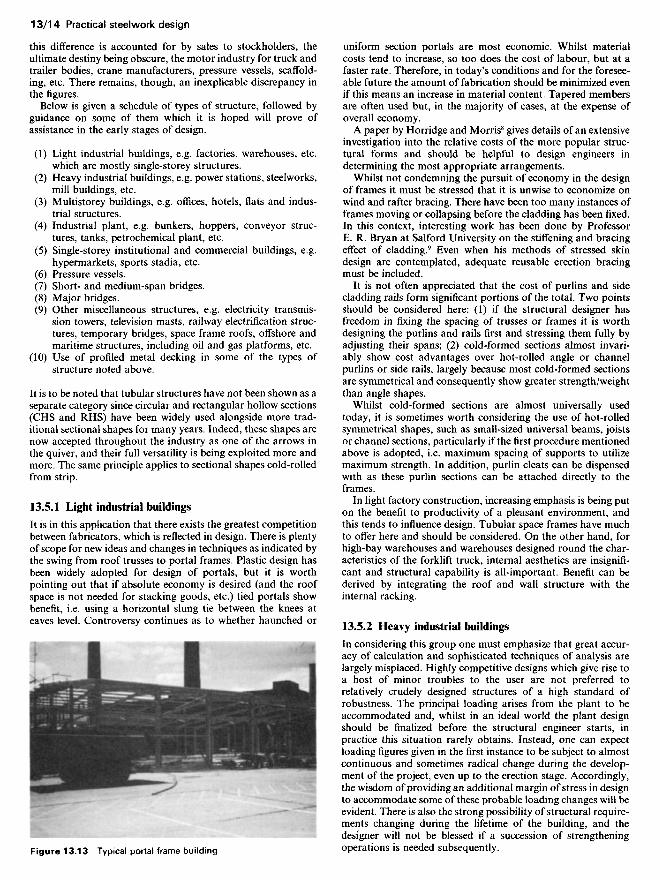
It is in this application that there exists the greatest competitionbetween fabricators, which is reflected in design. There is plentyof scope for new ideas and changes in techniques as indicated bythe swing from roof trusses to portal frames. Plastic design hasbeen widely adopted for design of portals, but it is worthpointing out that if absolute economy is desired (and the roofspace is not needed for stacking goods, etc.) tied portals showbenefit, i.e. using a horizontal slung tie between the knees ateaves level. Controversy continues as to whether haunched or
uniform section portals are most economic. Whilst materialcosts tend to increase, so too does the cost of labour, but at afaster rate. Therefore, in today's conditions and for the foresee-able future the amount of fabrication should be minimized evenif this means an increase in material content. Tapered membersare often used but, in the majority of cases, at the expense ofoverall economy.
A paper by Horridge and Morris8 gives details of an extensiveinvestigation into the relative costs of the more popular struc-tural forms and should be helpful to design engineers indetermining the most appropriate arrangements.
Whilst not condemning the pursuit of economy in the designof frames it must be stressed that it is unwise to economize onwind and rafter bracing. There have been too many instances offrames moving or collapsing before the cladding has been fixed.In this context, interesting work has been done by ProfessorE. R. Bryan at Salford University on the stiffening and bracingeffect of cladding.9 Even when his methods of stressed skindesign are contemplated, adequate reusable erection bracingmust be included.
It is not often appreciated that the cost of purlins and sidecladding rails form significant portions of the total. Two pointsshould be considered here: (1) if the structural designer hasfreedom in fixing the spacing of trusses or frames it is worthdesigning the purlins and rails first and stressing them fully byadjusting their spans; (2) cold-formed sections almost invari-ably show cost advantages over hot-rolled angle or channelpurlins or side rails, largely because most cold-formed sectionsare symmetrical and consequently show greater strength/weightthan angle shapes.
Whilst cold-formed sections are almost universally usedtoday, it is sometimes worth considering the use of hot-rolledsymmetrical shapes, such as small-sized universal beams, joistsor channel sections, particularly if the first procedure mentionedabove is adopted, i.e. maximum spacing of supports to utilizemaximum strength. In addition, purlin cleats can be dispensedwith as these purlin sections can be attached directly to theframes.
In light factory construction, increasing emphasis is being puton the benefit to productivity of a pleasant environment, andthis tends to influence design. Tubular space frames have muchto offer here and should be considered. On the other hand, forhigh-bay warehouses and warehouses designed round the char-acteristics of the forklift truck, internal aesthetics are insignifi-cant and structural capability is all-important. Benefit can bederived by integrating the roof and wall structure with theinternal racking.
13.5.2 Heavy industrial buildings
In considering this group one must emphasize that great accur-acy of calculation and sophisticated techniques of analysis arelargely misplaced. Highly competitive designs which give rise toa host of minor troubles to the user are not preferred torelatively crudely designed structures of a high standard ofrobustness. The principal loading arises from the plant to beaccommodated and, whilst in an ideal world the plant designshould be finalized before the structural engineer starts, inpractice this situation rarely obtains. Instead, one can expectloading figures given in the first instance to be subject to almostcontinuous and sometimes radical change during the develop-ment of the project, even up to the erection stage. Accordingly,the wisdom of providing an additional margin of stress in designto accommodate some of these probable loading changes will beevident. There is also the strong possibility of structural require-ments changing during the lifetime of the building, and thedesigner will not be blessed if a succession of strengtheningoperations is needed subsequently.Figure 13.13 Typical portal frame building

Figure 13.14 Anchor steelworks, Scunthorpe
13.5.3 Multistorey buildings
Steelwork for this application faces the severest competitionfrom concrete, so much so that a decade or so ago it seemed as ifit had almost been ousted from the scene, except for a few veryspecial applications. This had largely come about as a result offire regulations. There are signs, however, which indicate thatwith some of the newer concepts, particularly for very high-riseprestige office buildings, steelwork offers economic and practicalsolutions. Two factors have brought about this situation.Firstly, the fire regulations require the lift and stair well enclos-ures to be separated and protected from the spread of fire fromthe occupancy floors. Secondly, the current wind code CP3:1972,Part II, Chapter V requires larger transverse forces to be takenby the building than pertained a decade ago. What bettersolution could there be than to have a reinforced concrete corecontaining the lifts and services which is itself capable ofresisting transverse forces and surrounding it with a simple steelframe supporting only vertical forces? In certain cases, theheight and plan form of the core may require vertical post-tensioning to enable lateral forces to be resisted. This post-tensioning can be provided by the surrounding omce floors ifthese are suspended from the top of the core. Several examplesof such structures have been constructed; these have the addedadvantage, in city centre developments, of keeping all thefoundation work within the plan area of the building.
Two developments have taken place in multistorey buildingsin recent years. Firstly, the gas explosion at Ronan Point in 1968has led to the general recognition that structures need to haveadequate three-dimensional coherence if they are to be suffi-ciently resistant to accidental damage. This philosophy is nowembodied in section A3 of the Building Regulations,10 whichstates that in the event of misuse or accident, damage should notbe disproportionate to the cause. In truth, with very few
Figure 13.15 National Westminster Bank
Secondly, partly arising from the wide acceptance of sheetsteel composite floors (treated in detail in section 13.5.10) andthe savings in construction times thus brought about has come awider recognition of the economic savings accruing from rapidconstruction generally. Given that immediate occupation isanticipated, high interest rates dictate that the fastest method is,in the long run, the cheapest. This recognition has led to someincrease in the use of steelwork for multistorey buildings.
Having dealt shortly with the latest developments one muststate that now, and in the future, the bulk of multistorey steelframes will be discontinuous column and beam frames designedon simple methods. That is to say that beams are assumed to besimply supported and columns are assumed to carry only suchbending moments as arise from the end reaction of the beamsacting at a given eccentricity from the column centreline. Thismethod is easy and quick to apply and has stood the test of timein that failures in such structures are extremely rare indeed, andif they do occur it is usually due to instability during erection.However, it is important to realize that the stress values arrivedat in calculations bear little relationship to those actuallyexperienced by the frame. This is due primarily to the omissionof any consideration of joint stiffness between beam and col-umn. In practice a true simple support is very rare and, evenwith the simplest connection, some moment transference willtake place between them. In the event of both beams andcolumns being encased in concrete, the degree of joint stiffnesswill be considerable. Thus, the simple design method tends tooverestimate beam moments and underestimate column mo-ments.
This does not matter, certainly so far as internal columnssupporting beams of approximately equal span and loading are
In this class of structure there is not a great deal of scope fororiginality on the part of the designer. For the most part, plantrequirements dominate and the structural layout is not decided- it occurs. It is important, nonetheless, to ensure adequateeconomy by studying actual needs. For example, a steel meltingshop and a power station turbine house may demand cranes ofsimilar capacity but, whereas the ladle crane may make a dozenpasses a day at maximum load, the turbine house crane onlyneeds its full capacity for the replacement of a turbo-alternatorevery few years. Clearly, different levels of fatigue are present inthese instances, which results in quite different standards forstructural adequacy.
exceptions, any normal well-designed steel-framed multistoreybuilding will be found, on analysis, to comply automaticallywith the statutory requirements for peripheral and transversetying forces, although in design it is now necessary to check this.If difficulty is found in compliance, it should be taken as anindication that the basic structural anatomy is capable ofimprovement.

concerned, but outer columns (particularly corner columns)carrying asymmetrical moments deserve some thought, cer-tainly if uncased. Therefore, in a highly competitive design it isquite safe to trim the design of beams and internal columns tothe bone, even to accepting some degree of overstress, butleaving the face and corner columns conservatively designed.
The results of tests on full-scale structures (apart from testson isolated elements) have indicated a very considerable marginof strength in the columns, well in excess of any predictionsmade by elastic design. Clearly, further research is neededbefore this can be codified into a simple design method.
13.5.4 Industrial plant
In many respects this group is a speciality and indeed has itsown trade association. Design problems are likely to arise inmany respects, notably in connection with working stresses andwhether those specified in BS 449 and BS 5950 are applicableand appropriate. Judgement is required, particularly in respectof the possibility of overloading, accidental or deliberate.Clearly, tanks cannot be overloaded, and a slender load factormay be appropriate, whereas in some other applications normalload factors will result in structures insufficiently robust for theirpurpose.
In design, fatigue may be a consideration in dynamicallyloaded structures such as conveyor frames, gantry structures,etc. Reference to the BS 153, Part B or BS 5400, Part 10 ruleswill indicate whether this is a governing factor.
13.5.5 Single-storey institutional and commercialbuildings
In recent years a considerable increase in steel use has occurredin such buildings as leisure centres, swimming baths, cash andcarry warehouses, sports stadia, hypermarkets, exhibition halls,etc. to the extent of becoming a new classification. A studyreveals a very wide variety of different structural forms, includ-ing columns and beams, column and truss, arches, domes, spaceframes, etc. and it is clear that potential exists for the use ofimagination and inventiveness. However, they mostly share twocharacteristics: (1) that they are single-storey; and (2) requirethe roofing of large areas, mostly uninterrupted by internalcolumns. As such, the latter presents common problems, includ-ing the disposal of large quantities of rainwater, the provision ofservices of considerable total weight often within the roofstructure and, not least, the accommodation of temperaturemovements. This last is known to have caused problems in theplumbing of columns, when cladding sensitive to such move-ment was adopted. Provision must be made for movement jointsin the cladding of both roofs and walls, and also possibly in thestructure itself. In the absence of the latter in a large building itis futile to call for accuracy in plumb which is less than theanticipated total expansion.
Agreement as to total tolerance must be obtained at thedesign stage or disputes may subsequently arise. Further, liningand levelling of the final structure, before fixing the cladding, isbest done at night, when the structure has settled to an eventemperature with no differential between the shaded side andthat exposed to strong sunlight.
13.5.6 Pressure vessels
The design of pressure vessels forms the subject of a separateBritish Standard BS 5500:1985 Specification for unfired fusionwelded pressure vessels. The requirements laid down therein areconsiderably more stringent than for normal steelwork, both asregards material quality and fabrication, and inspection pro-cedures are correspondingly more severe. That this is right isundeniable, having regard to the catastrophic consequences ofpossible failure, but it does lead to fabrication costs greatly inexcess of the usual. Specialist plant is needed, such as thatnecessary to bend thick plates and spin dished ends.
In addition to the basic BS 5500 standard, the BSI alsopublish a series of Enquiry cases under the same number, whichare supplied free of charge to subscribers of the BS 5500updating service. These documents, which are numerous, pro-vide information on a wide variety of pressure vessel problems.
In 1982, the Pressure Vessels Quality Assurance Board(PVQAB) came into being; its prime purpose is to provide thepressure vessel industry with a means of recognition, bothnationally and internationally, of the quality of their products.The Board was originally set up under the aegis of the Institu-tion of Mechanical Engineers with the object of providing acentral UK authority capable of approving and certifying thequality assurance systems of pressure-vessel manufacturers,their products, and the material suppliers. It has now been takenover and is being run by Lloyd's. It is a similar scheme to thatoperated for many years by The American Society of Mechani-cal Engineers (ASME).
13.5.7 Short- and medium-span bridges
Competition with concrete is very severe. It will frequently befound that the most economic solution is arrived at by usingsteel beams or girders acting compositely with a reinforcedconcrete deck. In design it is no longer adequate to considerstatical transverse distribution. An analysis in accordance with
Figure 13.16 Plate girder for British Steel Corporation project,Scunthorpe, being welded
In such work, maintenance costs to prevent corrosion can beheavy. It is not sufficient to design and detail a steel structureand then ask oneself what means of protection should beapplied. It may by then be too late since moisture traps mayhave been built in and certain areas may be inaccessible forpainting after erection, e.g. back-to-back angles. Care must betaken in detailing to ensure that water cannot collect in puddles.If this situation is unavoidable, drain holes should be provided.The BSC publish two useful booklets11-12 which give simpleguidance. Chandler and Bayliss13 provide a practical guide tocurrent knowledge on coatings and processes involved inachieving sound protection of steelwork. It should be borne inmind that hot-dip zinc coating gives excellent protection atmodest cost and that the trend is for longer baths enablinggreater lengths and larger areas of steel to be treated.

Figure 13.17 Clunie Bridge, Pitlochry
In one such test which the authors witnessed, an ultimate loadfactor of 7 was achieved with a system in which the transversetop slab steel was discontinuous, i.e. over the beams only,calling into question the necessity for continuous top steel.
Girders may be rolled universal beams, or purpose-built plategirders, either with equal flanges or with a top flange smaller andnarrower than the bottom. In the latter case, the intermediatedesign stage must be examined when the laterally unrestrainedbeam is supporting the weight of the wet concrete. It is rare forsuch systems to be designed as propped, and thus compositeaction is assumed for live load only.
The theoretical advantage of unequal flanges giving minimumweight of steel will prove largely illusory if a rolled beam couldhave been used as an alternative. Minimum fabrication leads tominimum total cost. A steel bridge design guide by Nash16
illustrates the application of the new steel bridge code, BS5400:1982, Part3.
It is in the kind of bridge discussed, where the girders arelargely protected from driving rain, that the 'Cor-ten' or weath-ering steels are becoming popular. At small extra cost, bridgescan be built which will be effectively maintenance-free duringtheir life. Depending on the corrosion environment, the Depart-ment of Transport require a sacrificial 'skin' of either 1 or 2 mmon the exposed surfaces. To facilitate the use of rolled beams,modified tables of properties, omitting this 'skin' have beenpublished by Constrado.17
13.5.8 Major bridges
It is here that the designer has greatest scope for imaginationand inventiveness, as is illustrated by the wide variety of elegantstructures which have been built in recent years throughout theworld. Steel dominates the scene here, largely due to itsstrength .-weight ratio, since the greater part of the load sus-tained by a large-span bridge is its own self-weight. It is,unfortunately, given to few of us to have a hand in the design of
such works but, with increasing complexity, design becomes amatter of teamwork, and no one name can any longer beattached to one structure. On the other hand, the hazards aregreat, as events over the years have shown.
The considerable effort put into box-girder research follow-ing the collapse of four box-girder bridges in the early 1970shas been distilled into the new steel bridge code, BS5400:1982,Part 3.
13.5.9 Other miscellaneous structures
Within this group one should include electricity transmissiontowers (themselves something of a speciality), lighting masts,television masts, railway electrification structures, temporarybridges, footbridges, offshore structures, etc.
Structures frequently are evolved which could not be visual-ized by the drafting committees responsible for British Stan-dards, e.g. railway electrification structures supported only onone side of the track, gallows style. In this instance, tension inthe conductor wires can produce considerable torsion in thecolumn and severe moments arise when the track is on a curve.Accordingly, strict application of codes of practice for designneeds to be tempered by engineering judgement, and it isarguable whether the existing British Standards are really appli-cable in such cases.
Likewise, difficulties have been known to arise in transmissiontowers. Even greater line voltages have necessitated taller andtaller towers. Some years ago, 30 m was a tall tower; today, 75 mis not uncommon and for long river crossings even greaterheights are needed. It is not sufficient for the designer merely toextrapolate from existing designs. There will always be a tend-ency for the designer to assume that what is flat on his drawing,will also be planar when erected. This may be a reasonableassumption up to a certain size, but ceases to be accurate to alarger scale. Self-weight deflections of long members of latticestructures can become significant, particularly if the member isintended to act as a strut.
There was an obvious need for a rational approach to thedesign of lattice towers and masts which led the BSI to set up asteering committee in 1970 with the task of preparing a code ofpractice. The result of the drafting committee's deliberation isthe recently published BS 8100:1986 Lattice towers and masts,which interestingly does not supersede any current standard. Itis published in two parts, namely:
Part 1, 'Code of practice for loading'.Part 2, 'Guide to background and use of Part 1'.
This standard defines procedures for the determination ofloading for the design or appraisal of free-standing towers oflattice construction up to 300 m in height.
Part 2 includes two worked examples cross-referenced to therelevant clauses of the code. Also available is a draft fordevelopment DD 133:1986, Code of practice for strength assess-ment of members of lattice towers and masts which has beenissued in this form to enable industry to provide practicalfeedback in the light of experience so that ultimately a BritishStandard code under BS 5950 can be published.
Developments in the North Sea opened up a vast potentialmarket for steel structures. The sizes of many of those built sofar beggar description, and the limit has by no means beenreached. Again, it was arguable whether BS 449 really appliedand the design engineer was in many ways out on a limb and hadto work from first principles. To start with, the assessment ofloading was far from straightforward and much had to belearned about the effect of wave forces on structures of variousshapes. Temperature also had to be considered and the princi-ples of notch ductility and fatigue mentioned in sections 13.2.3
the theories of Hendry and Jaeger14 or Morice and Little,15 or afinite-element grillage analysis will demonstrate great economyin the sizes of beams at the expense of a minimum addition tothe transverse reinforcement in the slab. If full transversedistribution is assumed it is usual to provide continuous trans-verse top steel in the slab.
A number of model tests have been carried out on compositebridges designed to these principles (see also section 13.7.4.5).Departure from strict linearity occurs at around twice workingload, which indicates reasonable economy with adequate safety.Destructive tests, however, give enormous margins of strengthat collapse, ultimate load factors of 10 being common.

Figure 13.18 Electricity transmission tower. (Courtesy: CentralElectricity Generating Board)
Actual failure of some offshore structures has provided much-needed information and, having spelt out some fundamentallessons, one hopes that the experience gained will result in saferstructures in the future, although no doubt there are other trapsawaiting the unwary. As designers tend to overlook stabilityquestions on landbased structures in the part-erected condition,so also is there a danger of failing to recognize the situationwhen an offshore structure is being towed, usually on its side, toits final location. Buoyancy considerations arise which warrantmore than cursory attention.
13.5.10 Use of profiled metal decking in some of thetypes of structure noted in sections 13.5.1 to 13.5.9
In 1983, the first part of the new BS 5950 The use of structuralsteelwork in building was published; it was, in fact, numberedPart 4, 'Code of practice for the design of floors with profiledsteel sheeting'. This code is intended to assist both structuraldesigners and the construction industry in general in the selec-tion of steel deck floors for the most appropriate applications,and it is based on a recommendation made in 1970 by Commit-tee 11 of the European Convention for Constructional Steel-work (ECCS). In North America, floors of the type described inBS 5950, Part 4 have been incorporated in the construction ofmultistorey buildings since the early 1930s. In the early 1960sthis kind of floor was introduced into Western Europe wherethey are now widely used. Various interim recommendations
have been produced in North America and Europe coveringtheir analysis and design, but no standard specifications orcodes of practice have yet been published, although in the US astandard has been in the drafting stage for some years.
Profiled decking can be used noncompositely in the form ofpermanent shuttering or, more usually, compositely with con-crete for roof and floor slabs. This type of construction is beingspecified and used more each year because of its economic andperformance advantages over other more traditional forms offloor construction. The deck provides the positive reinforcementfor the slab and at the same time replaces the temporaryshuttering usually associated with reinforced concrete construc-tion. Once placed, the decking provides both an immediateworking platform for subsequent trades on the level on which itis laid and cover for the operatives working on the floors below.Thus, construction can proceed on several levels simultaneouslywhilst conforming more readily to the requirements of theHealth and Safety at Work Act 1974.
and 13.2.4 had to be observed. From this it follows that astructure satisfactorily designed for use in a tropical sea may notbe suitable, indeed may be downright dangerous, in Arcticconditions. The problems, therefore, required a conservativeapproach, tempered in the light of experience.
Figure 13.19 Metal decking
The use of this type of floor is not limited to steel structuresonly, since it is equally suitable for use in structures of rein-forced and precast concrete, timber or masonry.
The designer should appreciate that it is misleading simply tocompare costs of floors using profiled steel sheeting with othermore conventional forms of floor construction, since changes inoverall weight, stiffness and stability, composite action, speed ofconstruction, etc. will influence the cost relating to other parts ofthe supporting structure and foundations.
Recent building projects have shown quite clearly that theoverall building costs of structures using steel deck floors areconsiderably lower than those of structures utilizing other formsof construction. The reasons for these cost reductions have been

investigated in depth and confirmed in the findings of a reportby Walker and Gray.6
The advantages of using profiled steel decking may thereforebe summarized for both composite and noncomposite floors asfollows:
(1) Steel decks provide permanent formwork and do not nor-mally require the use of additional temporary formwork orpropping.
(2) The low weight of the steel deck unit means they can bemanhandled with comparative ease, thus reducing or elimi-nating mechanical handling costs.
(3) Faster construction times are obtained with improvedsafety.
(4) Maximum efficiency and cost-effectiveness is obtainedwhere regular grids are adopted, although the designer hasfreedom to arrange the structural support framing to ac-commodate irregular shapes.
(5) For floors acting compositely there is an efficient use of thetwo basic construction materials of steel and concrete, sincethe steel deck acts as both formwork and tensile reinforce-ment.
13.6 Overall structural behaviour
Having referred frequently to British Standards for design, i.e.BS 449, BS 153, BS 5400, BS 5500 and BS 5950, a word ofcaution is warranted. These documents, as all British Standards,are drafted by committees of experienced people drawn from allquarters, charged with the task of formulating design rules inthe light of the state of knowledge at the time, incorporating thebest modern practice and exploiting the latest research. This isno easy task. They recognize that many of those who would usethe documents would not understand, indeed would not want tounderstand, the background theory behind many of the require-ments. Inevitably, many areas of doubt and uncertainty areencountered and differences of opinion expressed. At the end ofthe day, they rightly tend on the conservative side in suchsituations though, in one or two instances, subsequent researchhas indicated that their rules were not sufficiently cautious in theearlier standards. However, these documents have stood the testof time and, by and large, when properly interpreted result instructures in which safety and economy are reasonably inbalance. But they tended to lay undue emphasis on the determi-nation of exact values of permissible stresses and insufficientattention (certainly in the case of BS 449) to questions of overallstructural behaviour and stability, particularly during erection.
The young designer can be forgiven for supposing that, if allmembers and connections in a structure are assessed anddesigned strictly in accordance with the British Standard, thenthe complete structure will be adequate for its task. In the greatmajority of cases this will be so, but in rare instances it has beenfound to be a fatal error. In a number of cases the designer has,unconsciously perhaps, relied on the stiffening effect of thecladding to provide overall stability and a collapse has occurred,sometimes under the weight of an erection crane before thecladding has been fixed. What one does not know, and cannotassess, is how many structures are satisfactorily in service whichwere within a hair's breadth of collapse at some stage duringerection. As an illustration, it may seem an economic solution inthe design of a frame for a multistorey building to have anumber of load-carrying plane frames, interconnected with lightties. In the absence of temporary bracing, such a structure reliesfor stability on the stiffness of the joints at the ends of the tiebeams. Such joints, being on nominally unloaded or lightmembers, are often regarded as being unimportant and aresometimes detailed as simple connections, instead of joints
which have some moment capacity. Thus, in the unclad state theframe possesses insufficient longitudinal stability. This illustra-tion is but one of many which could have been quoted but it ishoped that the point has been driven home. Overall supervisionof the design of both members and connections by a competentengineer, and the intelligent assessment of the problems by theerection supervisor, should be sufficient to prevent such mis-haps.
The stiffening effect of cladding, which has been referred to, isvery great indeed but, except in the case of very simple struc-tures, it is likely to remain impossible to assess in the foreseeablefuture. Because of this and because of the accidental andunquantifiable composite action which occurs between steelmembers and other materials, the actual stresses experienced inservice are likely to be very different and usually much lowerthan those calculated. This fact, coupled with the fact thatloadings which are specified, particularly wind loadings, are atbest only general estimates, means that great nicety of calcula-tion is largely misplaced. Thus, the pursuit of notional absoluteeconomy is a cardinal error if it means that under pressure oftime the consideration of overall behaviour is omitted.
A related problem frequently encountered and on which littleguidance is available, concerns the amount of sway or hori-zontal deflection permitted at the top of a tall multistoreybuilding under wind loading. It has been common to limit suchsway to 1/500 of the height, calculated on the stiffness of thebare steel frame. This largely begs the question, since most ofthe wind force would be absent without cladding. With it inplace, the deflection must be considerably reduced in conse-quence of its stiffening effect. What is being considered here isnot structural safety - that is not in question - but serviceability.In the absence of any knowledge at all of cases where discomforthas been caused to occupants or damage to finishes throughexcessive sway, the authors conclude that the above notionallimit is conservative. Clearly, long-term observations are calledfor which may take years to yield worthwhile data. Meanwhile,it is suggested that if the above limitation is deemed acceptablefor dwellings with curtain walling, then relaxation of the limi-tation would seem appropriate in respect of two factors:(1) other uses; and (2) stiffer cladding. Again, in city centres,the sheltering effect of neighbouring buildings may be taken intoaccount in assessing wind forces. Is one to take into account thepossibility of some, or all, of them being demolished some timein the future? Such considerations need careful assessment, andauthoritative advice.
13.7 Design of structural components
There would seem little point in including worked examples inthis section, in view of the fact that the old design standards areunlikely to be used for most new projects, whilst designs to thenew standards are doubtless covered in numerous recent publi-cations such as that by the Steel Construction Institute.
13.7.1 Importance of correct loading assessment
Great care should be taken in the assessment of dead and liveloading, as mistakes at this stage can make all subsequentcalculations abortive and, in extreme cases, result in completedmembers being scrapped. This has been known to happen andunfortunately not all that infrequently. Some common causes ofmistakes in this matter are: (1) failing to make adequate allow-ances for finishes as, for instance, in providing screeding to fallsin a roof slab to provide adequate drainage; (2) failure to makeproper allowance for surges in gantry structures; (3) incorrectinterpretation of wind loading requirements; and (4) effect onpressure of flow in granular materials, etc. Safety requires that a


![Untitled-1 [] · 2018. 11. 6. · SANS 10162 — Structural Steelwork SANS 10162 Part 2 — Limit States design of Cold Formed Structural Steelwork SANS 14713 — Protection against](https://static.fdocuments.in/doc/165x107/60bfca9edf84f3163d3d55fb/untitled-1-2018-11-6-sans-10162-a-structural-steelwork-sans-10162-part.jpg)


