PR-312S-PQ · PR-312S-PQ Indoor Proximity Card Reader Manual Stand-alone operation Status LEDs for...
16
PR-312S-PQ Indoor Proximity Card Reader Manual Stand-alone operation Status LEDs for operations and programming Solid-state lock relay for longer life, lower power consumption, and shock/vibration resistance Up to 500 user cards Up to 5 super user cards, plus 1 master card 10 Cards included (additional cards available – sold separately in packs of 10) Integrated doorbell button
Transcript of PR-312S-PQ · PR-312S-PQ Indoor Proximity Card Reader Manual Stand-alone operation Status LEDs for...

PR-312S-PQ
Indoor Proximity Card Reader
Manual
Stand-alone operation
Status LEDs for operations and programming
Solid-state lock relay for longer life, lower power consumption, and shock/vibration resistance
Up to 500 user cards
Up to 5 super user cards, plus 1 master card
10 Cards included (additional cards available – sold separately in packs of 10)
Integrated doorbell button
ENFORCER Indoor Proximity Card Reader
2 SECO-LARM U.S.A., Inc.
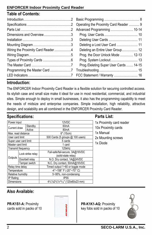
Power input 12VDC
Current draw Standby 60mA
Active 80mA
Max. read distance 6" (15cm)
User card limit 500 Cards (5 groups @ 100 users)
Super user card limit 5 cards
Master card limit 1 card
Transmit frequency 125kHz
Outputs
Lock strike relay Fail-safe/fail-secure, 3A@16VDC
(solid-state relay)
Doorbell relay N.O. Dry contact, 1A@24VDC
Tamper switch N.C. Dry contact, 50mA@16VDC
Relay time delay Timed output 1~60 or toggle mode
Temperature -4°~158° F (-20°~70° C)
Relative humidity 5~95%, non-condensing
IP Rating IP55
Dimensions 43/4"x23/8"x15/16" (120x60x23 mm)
Table of Contents: Introduction ...................................................... 2
Specifications .................................................. 2
Parts List ......................................................... 2
Dimensions and Overview ............................... 3
Installation ....................................................... 3
Mounting Diagram ........................................... 3
Wiring the Proximity Card Reader ................... 4
Wiring Diagram ................................................ 5
Types of Proximity Cards ................................ 6
The Master Card ............................................. 7
Programming the Master Card ........................ 7
LED Indicators ................................................. 7
Introduction: The ENFORCER Indoor Proximity Card Reader is a flexible solution for securing controlled access.
Its stylish case and small size make it ideal for use in most residential, commercial, and industrial
sites. Simple enough to deploy in small businesses, it also has the programming capability to meet
the needs of midsize and enterprise companies. Simple installation, high reliability, attractive
design, and scalability are all combined in the ENFORCER Proximity Card Reader.
Specifications: Parts List: 1x Proximity card reader
10x Proximity cards
1x Manual
2x Mounting screws
1x Diode
Basic Programming ........................................ 8
Operating the Proximity Card Reader ............ 9
Advanced Programming .......................... 10-14
Prog. User Cards ...................................... 10
Deleting User Cards ................................. 11
Deleting a Lost User Card ........................ 11
Deleting an Entire User Group .................. 12
Prog. the Door Unlock Mode ............... 12-13
Prog. System Lockout............................... 13
Prog./Deleting Super User Cards ........ 14-15
Troubleshooting ............................................ 15
FCC Statement / Warranty ........................... 16
Also Available:
PR-K1K1-AQ: Proximity key fobs sold in packs of 10
PR-K1S1-A: Proximity
cards sold in packs of 10

ENFORCER Indoor Proximity Card Reader
SECO-LARM U.S.A., Inc. 3
Dimensions and Overview:
Installation: 1. Unpack the unit and familiarize yourself
with the proximity card reader.
2. Test the mounting location of the proximity
card reader for fit.
3. Using a Philips screwdriver, remove the
screw from the bottom of the proximity card
reader and separate the outside case from
the base.
4. Place the base on the mounting location
and then mark the locations of the two
mounting holes and two wire holes.
5. Drill a 1/2” hole in the mounting location
through which wires can be run to the
proximity card reader.
6. Permanently screw the base to the
mounting location.
7. Run the wires from the power supply,
egress button, door unlocking device, and
other accessories as needed through the
hole to connect to the terminal block.
8. Connect the appropriate wires to the
proximity card reader’s terminal block.
9. Reattach the proximity card reader’s
outside case to the base.
10. The preliminary installation is done. The
proximity card reader is ready to power up
and program.
Mounting Diagram:
Front view Back view (cover removed)
Operation
indicator LEDs
Status LED
(blue)
Card reader
window Doorbell
button
Door lock
selection jumper
Terminal
block
Tamper
switch
CMC
Jumper
23/8” (60mm)
43 /4"
(12
0mm
)
7/8” (23mm)
Front View Side View
11/16” (27mm)
35/16 " (84m
m)
Base
Proximity card reader
Mounting screw
Wire holes Mounting
screw

ENFORCER Indoor Proximity Card Reader
4 SECO-LARM U.S.A., Inc.
Wiring the Proximity Card Reader:
Terminals 1 & 2 – 12VDC Power input: 1. Connect terminal 1 (+) to the positive output of a 12VDC power supply.
2. Connect terminal 2 (–) to the negative output of the power supply. Terminal 2 is also the
grounding point of the egress button.
NOTE: The 12VDC power supply must supply enough amperage to also power the door
lock/unlock device.
Terminals 3 & 4 – 12VDC Power output for the door lock/unlock device: 1. These terminals provide a max of 3A to power the door lock/unlock device.
2. Connect terminal 3 (+) to the positive input of the 12VDC door lock/unlock device.
3. Connect terminal 4 (–) to the negative input of the 12VDC door lock/unlock device.
NOTE: The door lock/unlock output is programmable for fail-safe or fail-secure operation via the
door lock selection jumper. See below to program for fail-safe or fail-secure operation.
a. Fail-safe electric locks – power ON to lock, OFF to unlock.
b. Fail-secure electric locks – power OFF to lock, ON to unlock.
Terminal 5 – EG IN (Egress input for a N.O. pushbutton egress button): 1. Mount one or more N.O. pushbuttons inside the protected premises as a way for someone
without a proximity card to easily unlock the electronic door lock and leave the room.
2. Connect one terminal of the N.O. pushbutton to terminal 5, and the other to the negative input
of the 12VDC power supply (terminal 2).
3. Multiple buttons can be connected in parallel.
Terminal 6 – Data I/O port: Reserved for future use. Terminals 7 & 8 – Doorbell relay output: 1. Connect to an optional N.O. doorbell or buzzer with a maximum draw of 1A@24VDC.
2. The doorbell sounds for as long as the bell button on the proximity card reader is held.
Terminals 9 & 10 – Tamper switch output: 1. N.C. Output, closed while the proximity card reader is properly attached to its base plate.
2. Connect to the tamper circuit of an optional alarm system.
3. If the proximity card reader is taken off its base, the tamper switch will trigger the alarm system.
1 2 3 4 5 6 7 8 9 10
(+) (–) (+) (–) EG
IN DATA
I/O DOOR BELL
N.O. TAMPER
N.C. 12VDC DOOR LOCK
Door Lock Selection Jumper: 1. SAFE (For fail-safe operation) 2. SECURE (For fail-secure operation)
ENFORCER Indoor Proximity Card Reader
SECO-LARM U.S.A., Inc. 5
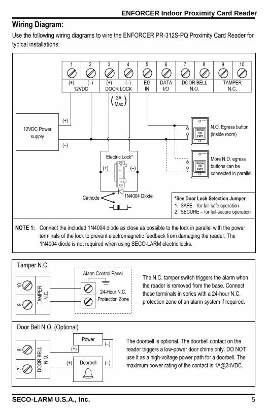
Wiring Diagram: Use the following wiring diagrams to wire the ENFORCER PR-312S-PQ Proximity Card Reader for
typical installations:
1 2 3 4 5 6 7 8 9 10
(+) (–) (+) (–) EG
IN DATA
I/O DOOR BELL
N.O. TAMPER
N.C. 12VDC DOOR LOCK
12VDC Power
supply
N.O. Egress button
(inside room)
More N.O. egress
buttons can be
connected in parallel
Electric Lock*
(+) (–)
(+)
(–)
*See Door Lock Selection Jumper 1. SAFE – for fail-safe operation 2. SECURE – for fail-secure operation
Cathode 1N4004 Diode
NOTE 1: Connect the included 1N4004 diode as close as possible to the lock in parallel with the power
terminals of the lock to prevent electromagnetic feedback from damaging the reader. The
1N4004 diode is not required when using SECO-LARM electric locks.
Tamper N.C.
Door Bell N.O. (Optional)
9 10
TA
MP
ER
N.C
.
7 8
DO
OR
BE
LL
N.O
.
The N.C. tamper switch triggers the alarm when
the reader is removed from the base. Connect
these terminals in series with a 24-hour N.C.
protection zone of an alarm system if required.
Alarm Control Panel
24-Hour N.C.
Protection Zone
The doorbell is optional. The doorbell contact on the
reader triggers a low-power door chime only. DO NOT
use it as a high-voltage power path for a doorbell. The
maximum power rating of the contact is 1A@24VDC. Doorbell
PUSH TO
EXIT
PUSH TO
EXIT
Power
(+) (–)
(–) (+)
3A Max ( )
ENFORCER Indoor Proximity Card Reader
6 SECO-LARM U.S.A., Inc.
Types of Proximity Cards: The proximity cards included with the proximity card reader, as well as additional blank proximity
cards and keyfobs, can be programmed for use in one of three ways (see pg. 3 for ordering
information):
Master Card Used to program features of the proximity card reader or to add/delete user and super user
cards. The master card will not unlock the door lock device.
When the PR-312S-PQ Proximity Card Reader is first installed, or if the existing master card is
lost, a new master card must first be configured before any programming can be done.
See page 7 to configure the master card.
User Cards Unlocks the door lock device by tapping or swiping the card near the proximity card reader.
Up to 100 user cards can be programmed per each group of users. There are five user groups,
for a maximum of 500 unique user cards.
Program or delete user cards by using the master card.
The user groups allow an entire group of user cards to be deleted at once.
For most simple implementations, it is easiest to put all the users (maximum of 100) into the
default user group, group #1.
Super User Cards Unlocks the door lock device like a user card, except that the card must be tapped or swiped
twice near the proximity card reader.
Allows trusted executives to disable the proximity card reader to prevent users from unlocking
the door with their user cards, and re-enable the proximity card reader to resume normal
operation. This function is useful for locking the proximity card reader at night or on the
weekend to prevent users from entering the protected premises.
Up to five super user cards: one for each user group.
“Tapping” vs. “Swiping” the Cards In the following programming section, the administrator is instructed to “tap” the master or user
cards one or more times. Instead of tapping the card on the reader, one could also pass or swipe
the card near the reader. However, from a programming point of view, tapping the card ensures the
signal was clearly given to the card reader, and makes it easier to count how many times the card
was used.

ENFORCER Indoor Proximity Card Reader
SECO-LARM U.S.A., Inc. 7
The Master Card: The master card is necessary to do any programming of the ENFORCER Proximity Card Reader.
It will be necessary to configure a master card if:
The proximity card reader is being installed for the first time, OR
The most recently configured master card is lost
Only one card can be programmed as the master card. Programming a new master card will
automatically delete the old one.
Programming the Master Card: To program the master card:
Step Action Reaction 1 Cut power to the proximity card reader
2 Move the CMC jumper from OFF to ON
(see “Overview” on page 3)
3 Restore power to the proximity card
reader
Reader starts beeping, and blue status LED
flashes to signal the start of a 1-minute
countdown for configuring the master card
4 Move the CMC jumper from ON to OFF Reader stops beeping
5 Tap a currently unused proximity card 2 Beeps
6
Press the “Bell” button to save the
master card code and exit the master
card configuration mode
2 Beeps
7 Label the card as “Master Card” and put
in a secure location
NOTE 1: If the master card is not correctly programmed within the 1-minute countdown period, the
blue status LED will turn off. In this case, repeat the above procedure.
NOTE 2: If the master card is lost, program a new master card by repeating the above procedure.
LED Indicators: 1. Status indicator (blue LED) – a steady ON during normal
operation, or flashes while the proximity card reader is in the
programming mode or in the lock-down mode.
2. Operation indicators (LEDs numbered 1~5) – show the status
of the proximity card reader while in the operation mode or in
the programming mode.
While the proximity card reader is in the operation mode
and it reads a programmed card, the LED corresponding
to that card’s user group turns to a steady ON.
While the proximity card reader is in the programming
mode, the LEDs show the status of the feature settings
(see “Programming” on page 8 for details). Front View
Status
indicator
Operation
indicators
Card reader
window
Doorbell
button

ENFORCER Indoor Proximity Card Reader
8 SECO-LARM U.S.A., Inc.
Basic Programming: Most businesses will require basic programming of a super user card and a limited number of user
cards. Follow the programming instructions on this page if the owning company fits these
requirements:
Max. 100 user cards
Max. 1 super user card
No need to change the default settings of the proximity card reader
NOTE: If more advanced programming is required, see “Advanced Programming” on page 10.
1. Program the master card (see page 7).
2. Program the user cards:
Step Action Reaction
1 Tap the master card 1 time Blue status LED flashes, and LED 1 flashes once
2 Wait 2 seconds 2 Beeps, then LEDs 1 through 5 flash
3 Press the “Bell” button once LED 1 turns to a steady ON
4 Wait 2 seconds 2 Beeps
5 Tap a blank user card 1 time 2 Beeps
6 For multiple user cards, repeat step 5 2 Beeps for each card confirms that the card was programmed into the reader
7 Exit programming by tapping the master card once
2 Beeps
NOTE: Do not program the same card twice. Once a card has been programmed, attempts to
program that card will be rejected with a single long beep of the proximity card reader.
3. Program the super user card:
Step Action Reaction
1 Tap the master card 5 times Blue status LED flashes, and LED 5 flashes once
2 Wait 2 seconds 2 Beeps, then LEDs 1 and 2 flash
3 Press the “Bell” button once LED 1 flashes once
4 Wait 2 seconds 2 Beeps, then LEDs 1 through 5 flash
5 Press the “Bell” button once LED 1 turns to a steady ON
6 Wait 2 seconds 2 Beeps
7 Tap a blank user card 1 time 2 Beeps
8 Exit programming by tapping the master card once
2 Beeps
The ENFORCER Indoor Proximity Card Reader is now ready for use.
ENFORCER Indoor Proximity Card Reader
SECO-LARM U.S.A., Inc. 9
Operating the Proximity Card Reader: Unlocking the door with a user card: 1. Tap the user card once.
2. Two beeps confirm that a valid user card was read. The LED corresponding to the user group
(1 through 5) flashes once while the door strike is opened.
3. Five beeps indicate that the user card was not programmed and is invalid.
Unlocking the door with a super user card: 1. Tap the super user card twice within 3 seconds.
2. Two beeps confirm that a valid super user card was read. The LED corresponding to the user
group (1 through 5) flashes once while the door strike is opened.
3. Five beeps indicate that the super user card was not programmed and is invalid.
Temporarily disable the proximity card reader with a super user card: 1. Tap the super user card on the reader once, and then press the “Bell” button within 3
seconds. 2. Two beeps confirm that the card reader is disabled. The blue status LED will flash slowly
(0.5 sec ON, 1 sec OFF) while the reader is disabled. 3. Five beeps indicate that the super user card was not programmed and is invalid.
NOTE 1: While the card reader is disabled, the blue status LED will flash slowly. The card reader
will reject all user cards during this time.
NOTE 2: While the card reader is disabled, the door can be opened using a super user card or by
pressing the egress button.
NOTE 3: The doorbell button works as normal whether the card reader is disabled or not.
Re-enable the proximity card reader with a super user card: 1. Tap the super user card on the reader once, and then press the “Bell” button within three
seconds. 2. Two beeps confirm that the card reader is now enabled. The card reader returns to normal
operation, and the blue status LED flashes turn to a steady ON. 3. Five beeps indicate that the super user card was not programmed and is invalid.
NOTE: Using the master card to program the card reader while it is disabled will automatically
re-enable the reader upon exiting the programming mode. This allows the master card
user to retain control of the system even if the super user card is lost.

ENFORCER Indoor Proximity Card Reader
10 SECO-LARM U.S.A., Inc.
Advanced Programming: This section includes complete programming information. For a typical installation that does not
need full programming, see Basic Programming (page 8).
Adding User Cards: The ENFORCER Proximity Card Reader can learn up to 500 user cards. This memory is divided
into five user card groups, each of which holds a maximum of 100 user cards.
For a simple installation, all of a company’s users (up to 100) can be put into the same user card
group. Alternately, they can be split between two or more groups to make it easier to delete an
entire group’s user cards at once. For instance, user cards given to a group of temporary workers
could be programmed into their own user card group. All the cards in that group can then be
deleted once the workers leave.
Step Action Reaction
1 Tap the master card 1 time Blue status LED flashes, and LED 1 flashes once
2 Wait 2 seconds 2 Beeps, then LEDs 1 through 5 flash
3 Press the “Bell” button one or more times to choose a user card group from 1 to 5
The LED corresponding to the chosen user groups turns to a steady ON to indicate that the user group is ready to receive user card codes; if the LED flashes, that user card group is full and cannot accept new cards
4 Wait 2 seconds 2 Beeps
5 Tap a blank user card 1 time 2 Beeps
6 To add multiple user cards, repeat step 5, or steps 3-5 to add to other groups
2 Beeps for each card confirms that the card was programmed into the reader
7 Exit programming by tapping the master card once
2 Beeps
NOTE: Once a user card has been programmed into the reader, it cannot be added to the same or
another user card group. A long beep indicates that the user card is in use and will not be
added a second time.
ENFORCER Indoor Proximity Card Reader
SECO-LARM U.S.A., Inc. 11
Advanced Programming (continued): Deleting User Cards: There are three ways to delete user cards:
1. Delete a single user card.
2. Delete a lost user card.
3. Delete a group of user cards.
Step Action Reaction
1 Tap the master card 2 times Blue status LED flashes, and LED 2 flashes once
2 Wait 2 seconds 2 Beeps, then LEDs 1, 2, and 3 flash
3 Press the “Bell” button once LED 1 turns to a steady ON
4 Wait 2 seconds 2 Beeps
5 Tap the user card to be deleted once The card’s user group LED flashes once for 1 second; 2 Beeps
6 To delete multiple user cards, repeat step 5
The card’s user group LED flashes once for 1 second; 2 Beeps
7 Exit programming by tapping the master card once
2 Beeps
Deleting a Lost User Card: A specific lost user card can only be deleted if the owner of the proximity card reader has kept
careful records of each user card number and the user of that card. Deleting a particular user card
requires the use of the user card which was programmed immediately prior to the lost user card.
For example, if user card 7 in user group 3 was lost, to delete it, the administrator would need
access to user card 6 in user group 3.
Step Action Reaction
1 Tap the master card 2 times Blue status LED flashes, and LED 2 flashes once
2 Wait 2 seconds 2 Beeps, then LEDs 1, 2, and 3 flash
3 Press the “Bell” button twice LED 2 turns to a steady ON
4 Wait 2 seconds 2 Beeps
5 Tap the user card which was programmed immediately before the lost user card once
The lost card’s user group LED flashes once for 1 second; 2 Beeps
6 To delete multiple user cards, repeat step 5
The lost card’s user group LED flashes once for 1 second; 2 Beeps
7 Exit programming by tapping the master card once
2 Beeps
NOTE 1: If user card 1 in a particular user group is lost, it can be deleted by using the super user
card for that group.
NOTE 2: Any new user cards programmed into the reader will automatically fill any empty spots.
For example, if user card 7 in user group 3 was deleted, the next new user card added to
user group 3 will be the new user card 7.
Deleting a Single User Card:
ENFORCER Indoor Proximity Card Reader
12 SECO-LARM U.S.A., Inc.
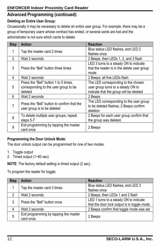
Advanced Programming (continued): Deleting an Entire User Group: Occasionally it may be necessary to delete an entire user group. For example, there may be a
group of temporary users whose contract has ended, or several cards are lost and the
administrator is not sure which cards to delete.
Step Action Reaction
1 Tap the master card 2 times Blue status LED flashes, and LED 2 flashes once
2 Wait 2 seconds 2 Beeps, then LEDs 1, 2, and 3 flash
3 Press the “Bell” button three times LED 3 turns to a steady ON to indicate that the reader is in the delete user group mode
4 Wait 2 seconds 2 Beeps; all five LEDs flash
5 Press the “Bell” button 1 to 5 times, corresponding to the user group to be deleted
The LED corresponding to the chosen user group turns to a steady ON to indicate that the group will be deleted
6 Wait 2 seconds 2 Beeps
7 Press the “Bell” button to confirm that the user group is to be deleted
The LED corresponding to the user group to be deleted flashes; 2 Beeps confirm deletion
8 To delete multiple user groups, repeat steps 5-7
2 Beeps for each user group confirm that the group was deleted.
9 Exit programming by tapping the master card once
2 Beeps
Programming the Door Unlock Mode: The door unlock output can be programmed for one of two modes:
1. Toggle output 2. Timed output (1~60 sec)
NOTE: The factory default setting is timed output (2 sec).
To program the reader for toggle:
Step Action Reaction
1 Tap the master card 3 times Blue status LED flashes, and LED 3 flashes once
2 Wait 2 seconds 2 Beeps, then LEDs 1 and 2 flash
3 Press the “Bell” button once LED 1 turns to a steady ON to indicate that the door lock output is in toggle mode
4 Wait 2 seconds 2 Beeps confirm that toggle mode was set
5 Exit programming by tapping the master card once
2 Beeps
ENFORCER Indoor Proximity Card Reader
SECO-LARM U.S.A., Inc. 13
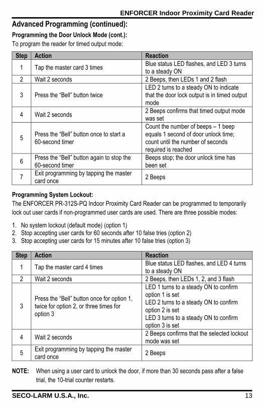
Advanced Programming (continued): Programming the Door Unlock Mode (cont.): To program the reader for timed output mode:
Step Action Reaction
1 Tap the master card 3 times Blue status LED flashes, and LED 3 turns to a steady ON
2 Wait 2 seconds 2 Beeps, then LEDs 1 and 2 flash
3 Press the “Bell” button twice LED 2 turns to a steady ON to indicate that the door lock output is in timed output mode
4 Wait 2 seconds 2 Beeps confirms that timed output mode was set
5 Press the “Bell” button once to start a 60-second timer
Count the number of beeps – 1 beep equals 1 second of door unlock time; count until the number of seconds required is reached
6 Press the “Bell” button again to stop the 60-second timer
Beeps stop; the door unlock time has been set
7 Exit programming by tapping the master card once
2 Beeps
Programming System Lockout: The ENFORCER PR-312S-PQ Indoor Proximity Card Reader can be programmed to temporarily
lock out user cards if non-programmed user cards are used. There are three possible modes:
1. No system lockout (default mode) (option 1) 2. Stop accepting user cards for 60 seconds after 10 false tries (option 2) 3. Stop accepting user cards for 15 minutes after 10 false tries (option 3)
Step Action Reaction
1 Tap the master card 4 times Blue status LED flashes, and LED 4 turns to a steady ON
2 Wait 2 seconds 2 Beeps, then LEDs 1, 2, and 3 flash
3 Press the “Bell” button once for option 1, twice for option 2, or three times for option 3
LED 1 turns to a steady ON to confirm option 1 is set LED 2 turns to a steady ON to confirm option 2 is set LED 3 turns to a steady ON to confirm option 3 is set
4 Wait 2 seconds 2 Beeps confirms that the selected lockout mode was set
5 Exit programming by tapping the master card once
2 Beeps
NOTE: When using a user card to unlock the door, if more than 30 seconds pass after a false
trial, the 10-trial counter restarts.
ENFORCER Indoor Proximity Card Reader
14 SECO-LARM U.S.A., Inc.
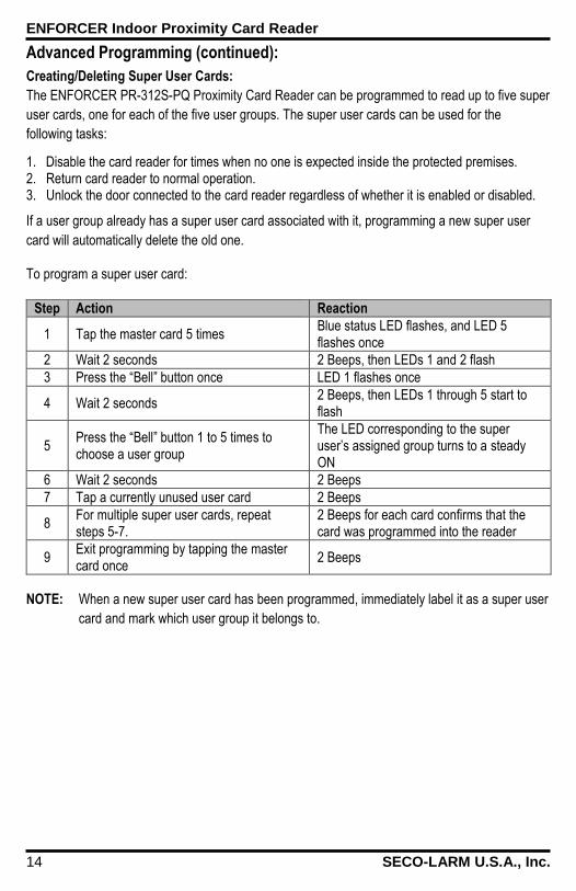
Advanced Programming (continued): Creating/Deleting Super User Cards: The ENFORCER PR-312S-PQ Proximity Card Reader can be programmed to read up to five super
user cards, one for each of the five user groups. The super user cards can be used for the
following tasks:
1. Disable the card reader for times when no one is expected inside the protected premises. 2. Return card reader to normal operation. 3. Unlock the door connected to the card reader regardless of whether it is enabled or disabled.
If a user group already has a super user card associated with it, programming a new super user
card will automatically delete the old one.
To program a super user card:
Step Action Reaction
1 Tap the master card 5 times Blue status LED flashes, and LED 5 flashes once
2 Wait 2 seconds 2 Beeps, then LEDs 1 and 2 flash
3 Press the “Bell” button once LED 1 flashes once
4 Wait 2 seconds 2 Beeps, then LEDs 1 through 5 start to flash
5 Press the “Bell” button 1 to 5 times to choose a user group
The LED corresponding to the super user’s assigned group turns to a steady ON
6 Wait 2 seconds 2 Beeps
7 Tap a currently unused user card 2 Beeps
8 For multiple super user cards, repeat steps 5-7.
2 Beeps for each card confirms that the card was programmed into the reader
9 Exit programming by tapping the master card once
2 Beeps
NOTE: When a new super user card has been programmed, immediately label it as a super user
card and mark which user group it belongs to.
ENFORCER Indoor Proximity Card Reader
SECO-LARM U.S.A., Inc. 15
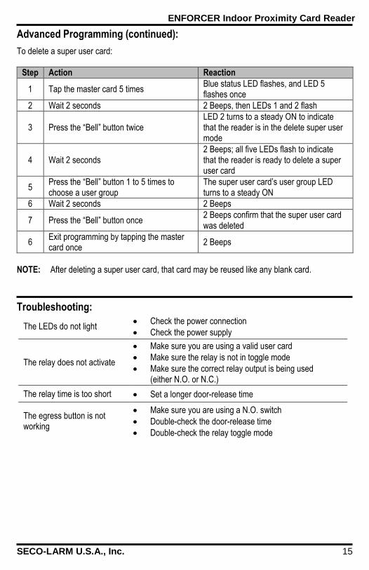
To delete a super user card:
Step Action Reaction
1 Tap the master card 5 times Blue status LED flashes, and LED 5 flashes once
2 Wait 2 seconds 2 Beeps, then LEDs 1 and 2 flash
3 Press the “Bell” button twice LED 2 turns to a steady ON to indicate that the reader is in the delete super user mode
4 Wait 2 seconds 2 Beeps; all five LEDs flash to indicate that the reader is ready to delete a super user card
5 Press the “Bell” button 1 to 5 times to choose a user group
The super user card’s user group LED turns to a steady ON
6 Wait 2 seconds 2 Beeps
7 Press the “Bell” button once 2 Beeps confirm that the super user card was deleted
6 Exit programming by tapping the master card once
2 Beeps
NOTE: After deleting a super user card, that card may be reused like any blank card.
Troubleshooting: The LEDs do not light
Check the power connection
Check the power supply
The relay does not activate
Make sure you are using a valid user card
Make sure the relay is not in toggle mode
Make sure the correct relay output is being used (either N.O. or N.C.)
The relay time is too short Set a longer door-release time
The egress button is not working
Make sure you are using a N.O. switch
Double-check the door-release time
Double-check the relay toggle mode
Advanced Programming (continued):
ENFORCER Indoor Proximity Card Reader
16 SECO-LARM U.S.A., Inc.
NOTICE: The information and specifications printed in this manual are current at the time of publication. However, the
SECO-LARM policy is one of continual development and improvement. For this reason, SECO-LARM reserves the right to change specifications without notice. SECO-LARM is also not responsible for misprints or typographical errors. Copyright © 2014 SECO-LARM U.S.A., Inc. All rights reserved. This material may not be reproduced or copied, in whole or in part, without the written permission of SECO-LARM.
WARRANTY: This SECO-LARM product is warranted against defects in material and workmanship while used in normal
service for one (1) year from the date of sale to the original customer. SECO-LARM’s obligation is limited to the repair or replacement of any defective part if the unit is returned, transportation prepaid, to SECO-LARM. This Warranty is void if damage is caused by or attributed to acts of God, physical or electrical misuse or abuse, neglect, repair or alteration, improper or abnormal usage, or faulty installation, or if for any other reason SECO-LARM determines that such equipment is not operating properly as a result of causes other than defects in material and workmanship. The sole obligation of SECO-LARM and the purchaser’s exclusive remedy, shall be limited to the replacement or repair only, at SECO-LARM’s option. In no event shall SECO-LARM be liable for any special, collateral, incidental, or consequential personal or property damage of any kind to the purchaser or anyone else.
SECO-LARM® U.S.A., Inc.
16842 Millikan Avenue, Irvine, CA, 92606 Website: www.seco-larm.com PIHAK1
Phone: (949) 261-2999 | (800) 662-0800 Email: [email protected] MiPR-312S-PQ_140818.docx
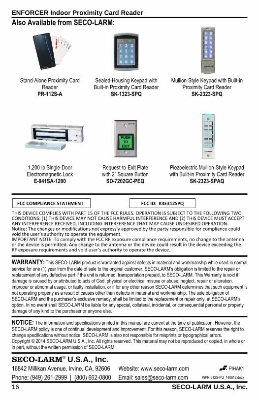
Also Available from SECO-LARM:
Stand-Alone Proximity Card Reader
PR-112S-A
Sealed-Housing Keypad with Built-in Proximity Card Reader
SK-1323-SPQ
Mullion-Style Keypad with Built-in Proximity Card Reader
SK-2323-SPQ
1,200-lb Single-Door Electromagnetic Lock
E-941SA-1200
Request-to-Exit Plate with 2” Square Button
SD-7202GC-PEQ
Piezoelectric Mullion-Style Keypad with Built-in Proximity Card Reader
SK-2323-SPAQ
THIS DEVICE COMPLIES WITH PART 15 OF THE FCC RULES. OPERATION IS SUBJECT TO THE FOLLOWING TWO CONDITIONS: (1) THIS DEVICE MAY NOT CAUSE HARMFUL INTERFERENCE AND (2) THIS DEVICE MUST ACCEPT ANY INTERFERENCE RECEIVED, INCLUDING INTERFERENCE THAT MAY CAUSE UNDESIRED OPERATION. Notice: The changes or modifications not expressly approved by the party responsible for compliance could void the user’s authority to operate the equipment. IMPORTANT NOTE: To comply with the FCC RF exposure compliance requirements, no change to the antenna or the device is permitted. Any change to the antenna or the device could result in the device exceeding the RF exposure requirements and void user’s authority to operate the device.
FCC COMPLIANCE STATEMENT FCC ID: K4E312SPQ


![000’(-...P7 Ł7 O PQ P ƒ7 Q P7 R S7 M12 ƒ[/ 012! P7 Ł7 O PQ? @7 O PQ V ₁12 X,2 / 012 &&" P7 Ł7 O PQ PH uH • MN2 uQ ó PQ è Q í @12 O PQ º ˇ7 u] &(& P7 Ł7 O PQ Y ⁄2](https://static.fdocuments.in/doc/165x107/5f061dee7e708231d4165fd6/000a-p7-7-o-pq-p-7-q-p7-r-s7-m12-012-p7-7-o-pq-7-o-pq-v-a12.jpg)