PPT Thrust Stand - NASA · variable differential transformer (LVDT) measured thrust The LES-8/9 PPT...
14
NASA-TM-107066 NASA Technical Memorandum 107066 / qq6_oOOglSq AIAA-95-2917 PPT Thrust Stand Thomas W. Haag Lewis Research Center Cleveland, Ohio Prepared for the 31st Joint Propulsion Conference and Exhibit cosponsored by AIAA, ASME, SAE, and ASEE San Diego, California, July 10-12, 1995 - e r_ ' NationalAeronauticsand , [[_l_/',tp_t _'lq_r.- " i SpaceAdministration ..... _!/IRGIt/I A i https://ntrs.nasa.gov/search.jsp?R=19960008159 2019-05-29T08:13:00+00:00Z
Transcript of PPT Thrust Stand - NASA · variable differential transformer (LVDT) measured thrust The LES-8/9 PPT...

NASA-TM-107066
NASA Technical Memorandum 107066 /qq6_oOOglSqAIAA-95-2917
PPT Thrust Stand
Thomas W. HaagLewis Research CenterCleveland, Ohio
Prepared for the31st Joint Propulsion Conference and Exhibitcosponsored by AIAA,ASME, SAE, and ASEESan Diego, California, July 10-12, 1995
-
e r_ '
NationalAeronauticsand , [[_l_/',tp_t_'lq_r. - " i
SpaceAdministration ..... _!/IRGIt/I A i
https://ntrs.nasa.gov/search.jsp?R=19960008159 2019-05-29T08:13:00+00:00Z
NASA Technical Library L
3 1176 01423 5098 ,
PPT Thrust Stand
Thomas W. Haag• National Aeronauticsand Space Administration
Lewis Research CenterCleveland, Ohio 44135
Abstract
A torsional-type thrust stand has been designed and built to test Pulsed Plasma Thrusters (PPTs)in both single shot and repetitive operatingmodes. Using this stand, momentum per pulse was determinedstrictly as a function of thrust stand deflection, spring stiffness, and natural frequency. No empiricalcorrections were required. The accuracy of the method was verified using a swinging impact pendulum.Momentum transfer data between the thrust stand and the pendulum were consistent to within 1 percent.Following initial calibrations, the stand was used to test a Lincoln Experimental Satellite (LES-8/9)thruster. The LES-8/9 system had a mass of approximately 7.5 kg, with a nominal thrust to weight ratioof 1.3 x 10⁻⁵. A total of 34 single shot thruster pulses were individually measured. The average impulsebit per pulse was 266 12N-s, which was slightly less than the value of 300 /2 N-s published in previousreports on this device. Repetitive pulse measurements were performed similar to ordinary steady-statethrust measurements. The thruster was operated for 30 minutes at a repetition rate of 132 pulses perminute and yielded an average thrustof 573 12N. Using average thrust, the average impulse bit per pulsewas estimated to be 260 12N-s, which was in agreement with the single shot data. Zero drift during therepetitive pulse test was found to be approximately 1 percent of the measured thrust.
A program to develop advanced PPTs for futuremission applications has been initiated. 4 Goals of this
Pulsed plasma thrusters (PPTs) are electric program are to increasedelivered total impulse by a factor ofpropulsion devices in which the propellant is accelerated two while reducing system mass by the same factor aselectromagnetically. Pulse durations are typically on the compared to state-of-artdevices. New propellant options areorder of one to ten microseconds. PPTs were studiedduring also being explored.5 Direct thrust measurements will bethe 1960's and tested by the US in an orbital flight essential to the success of this program. Impulse bits onexperiment launched in 1968.1 Operational status was the order of 300 12N-s are anticipated from thrusters withreached on board NOVA navigation satellites beginning in several kilograms mass. The average thrust-to-weight ratio1981.2 The NOVA system uses solid fluorinated polymer is significantlybelow that of steady-state electric propulsionas an ablatively dispensed propellant and is fired at a (EP) devicesand a specialized thrustbalance is required.repetition rate of up to 1 pulse per second. The unit has an The most sensitive PPT impulse measurementaverage power input of about 30 wattsand achieves specific capability in the United States was developed by Goddardimpulse values approaching 1000 seconds. The small Space Hight Center during the early 1970s.6 Designated asimpulse bits of each f'wing are used for very fine orbital the Micropound Extended Range Thrust Stand (MERTS),corrections of the NOVA vehicle, and the PPT is currently this device was used to measure both individual pulses andperforming this mission successfully) average repetitive thrust at levels down to 25 12N. A
Recent interest in small satellites has sparked custom-built differential plate capacitance system was usedrenewed interest in PPTs. Available electric power on to measure thrust stand deflections to a resolution of 2.5 xsmall satellites may be limited to less than 0.01 kW, which 10.8 m. Both a null balance method and a calibratedeliminates most steady-state forms of electric propulsion displacement method were implemented. A rotary thrusterfrom consideration. PPT power throttling is managed mount was used to vector the plume at different angles insimply by reducing the pulse repetition rate and does not order to determine asymmetric side forces. Oscillation
, affect performance. The simplified solid propellant damping was accomplished with an electronic feedbackdistribution arrangement of PPTs eliminates the need for circuit acting through an electromagnetic driver. A wirelessvalves, tanks, or precision metering components. Strict system of optical and radio links was used for thruster
• temperature controls often required for pressurized fluid telemetry and control. The thrust stand also had a built-in,propellants are also eliminated. Being a relatively inert variable-position, counterweight arrangement and requiredsolid, fluorinated polymer does not require special handling no special adjustments to operate thrusters of very differentprotection often needed when loading toxic liquid weight or thrust levels. Calibration was performed bypropellants, sending current through an electromagnetic forcing coil.

This method was used for pulsed and steady-state Pulse_tPlasmaThrusterscalibration.
Testing at the MIT Lincoln Laboratory was PPTsareatypeofmagnetoplasmadynamicthrusterperformed with a simple pendulum thrust stand.7 The in that they accelerate propellant predominantly throughthrusterwas fired in synchronismwith the natural frequency electromagnetic forces. With a PPT this occurs during aof the pendulum, resulting in an observable build up of brief but powerful pulse, typically at peak powers in theoscillatory motion. Measuring the changes in amplitude MW range and for durations on the order of microseconds.allowed determination of the average value of impulse per This pulsed mode allows performance and benefitsshot. associated with high power to be attained with low average
A Pulsed Electrothermal Thruster (PET) was tested power systems. While early development of PPTsby GT-Devices in the mid 1980s.s Liquid water flashedto a employed gaseous propellant, a solid fluorinated polymervapor and was heated in an arc discharge to propel the PET. rod has replaced gas in most applications. Solid propellantWater PETs could be operated in single pulse or repetitive is vaporized throughablation, eliminating the need for fastmodes. The thrust stand used to test the PET consisted of a acting gas valves and flow control.linear rail arrangement passing through the vacuum tank, A PPT is prepared for fh-ingby first charging theand sealed with a flexible diaphragm. Typical impulse bit main storage capacitor. The charge rate can be determinedmeasurements were on the order of 5 mN-s. Impulse was by the spacecraft power limitations without affectingdetermined by observing the instantaneous velocity change thruster performance. The electrodes can remain directlyof the thrust stand as a result of thruster firing. An connected to the capacitor during the charging cycle as longinductive proximetry probe provided displacement as there is no conductive path from anode to cathode. Eveninformation, which was then differentiated to obtain at a full charge of 1000 V the thruster is designed not to firevelocity. The system was calibrated by striking the thrust spontaneously. The discharge is commonly triggered usingstand with a solid pendulum. Thrust stand response was a semiconductor spark plug. This device emits a smallcompared with the known momentum delivered by the quantity of free electrons when activated, and brings aboutpendulum, an avalanche breakdown across the main electrodes. As the
A torsional thruststand was developed by Fairchild capacitor is discharged, polymer from the surface isRepublic Co. in the mid 1970s for the purpose of testing vaporized and ionized into a current carrying plasma. ThePPTs.9 Both individual pulse and repetitiveoperation were plasma is ejectedfrom the thruster via Lorentz forces createdperformed at thrust levels down to 200 //N. Leveling by the discharge. Once the discharge is extinguished themotors maintained the correct null position and a linear main capacitor may be recharged for the next pulse.variable differential transformer (LVDT) measured thrust The LES-8/9 PPT was designed to operate at astand deflections. An oil filled fluidic damper was used to nominal average power of 30 watts, and a pulse repetitiondissipate oscillations resulting from the thruster firing. A rate of about 2 Hz. There are two separate discharge portsball calibrator was developed to provide in-situ thrust stand on each thrusterassembly which are vectored at 60 degreescalibrations. Steel ball bearings were conveyed upward and to each other. Each port has a separatepair of electrodes andallowed to accelerate down an inclined plane, where they propellant track, but both sides share the same storageimpacted the thrust stand. Data from the calibration was capacitor and charging system. Each thruster port iscompared directly with that of actual thruster operation to controlled independently through signal wires. The thrusterquantifyperformance, was designed to deliver a nominal 300 /2N-s impulse bit
Following the completion of earlier PPT from either port. It has a mass of about 7.5 kg,development programs, both the Goddard and Fairchild representingan averagethrust to weight ratio of about 1.3 xthruststands were eventually discarded. A new thrust stand 10-5.has recently been built and tested for the purpose ofevaluating the Lincoln Experimental Satellite thruster(LES-8/9) and future generation PPTs. This stand employs Principleof ImpulseMeasurement_a torsional design, similar in size to that used by Goddardand Fairchild,6,9and has been used to measure individual Impulse can be defined as the cumulative effect ofthrust pulses as well as average thrust during times of an applied force over a specific time interval. It can berepetitivepulsed operation. Pivot arm movement is damped shown that the impulse needed to propel a body is simplyelectromechanically through a feedback loop, which can the product of its mass and velocity. According tosmooth the thrust signal at pulse rates down to about 1 Hz. Newton's third law, the mutual reaction force between the
This report discusses the details of the new thrust propellant and the thruster occur at the same magnitude andbalance and gives examples of actual PPT performance, for the same duration of time. The impulse delivered to theThe impulse bits of individual thruster pulses are presented, propellant is identical, but in opposite direction to that ofand these measurements are compared to time averaged the thruster. The thruster, of mass m, recoils in response tothrust values obtained during repetitiveoperation, a dischargesuch that
2
I determined by counting the undamped frequency ofv=--- (1) oscillation of the thrust stand. Using the above measured
m quantities, the unknown impulse bit is calculated as
' where v is the recoil velocity, and I is the impulse delivered, xkUnfortunately, the sinnsoidal movement typical of most 1=- (8)thrust stands makes instantaneous velocity measurements t°n
o difficult. Velocity must be measured the instant after thethruster fires, which introduces possible noise problems dueto electromagnetic interference and structural harmonies.An alternative is to obtain critical signal data after suchdisturbances subside. Conservation of energy makes thistechnique possible. The kinetic energy E delivered to the ThrustStandDesignthruster is
Momentum impulse measurements areconsiderably different from conventional steady-state thrust
E = lmv2 (2) measurements. Pulsed operation imparts highly transient2forces to the thrust stand which require special
If the recoiling thruster collides with an elastic spring such consideration. Also, PPTs typically have very low thrustthat energy is conserved (i.e. frictionless), then all of the to weight ratios which make accurate resolution difficult.kinetic energy will be transformed into strain energy in the Initial attempts at using a modified arcjet thrustspring such that stand were met with marginal success. The arcjet stand
featured a four bar linkage, inverted pendulumconfiguration. 1° While this linkage design maintained
E = lmv2 _ lkx2 (3) constant thrust axis alignment with the facility, its added2 2 complexity resulted in less precise movement than required
and a somewhat jittery response with pulsed thrusterwhere k is the spring stiffness, and x is the spring applications. Because of this, a new torsional thrust standdeformation. By rearranging eq(3), the maximum design was built specifically for testing the PPT. A simpledeformationof the spring becomes torsional thrust stand has only one rotational axis, and is
inherently more stable than an inverted pendulumI-'--
v-I m (4). arrangement. There is much precedent for using a torsionalxarrangement with PPTs, such as the MERTS and FairchildRepublic installations.3,9 A torsional thrust stand basically
Substitutingeq(1) into eq(4) consists of a swinging gate structure which is free to rotateabout a vertical axis. The thruster is mounted on the end of
I the gate or arm, at some radial distance from the center of
x = _ (5). rotation. The thrust axis is aligned to be tangent to thesweepingmotion of the arm, such that when the thruster isfired, the ann responds by rotating about its axis. This
When using a torsional thrust stand, the inertial term m can rotation is opposed by a torsional restoring force whichbe difficult to quantify directly due to the radial distribution returns the arm to a designated neutral position once theof various masses. However, all spring-mass systems have thruster is turned off. With most thrust stand designs, thea characteristicnatural frequency, 09n, determinedby stiffness of the restoring force is very linear and repeatable.
For steady-state operation, measured displacement may be
used as a means of comparison between the unknownton = (6) engine thrust and an established calibration force. Pulsedthrust measurements must be obtained differently since thespring-mass time constant of a thrust stand is often orders
Substitutingfor the mass term in eq(5) yields of magnitude longer than the duration of the actual pulse.Detailed explanations of these issues are included in the
D Icon followingsection.x = _ (7).k The thrust stand described herein was built in three
separate sections (Fig. 1). A torsional ann supported the' When used operationally, x is measured as the maximum PPT and counterweights. The rotational axis of the arm
deflection of the thrust stand after an impulse is applied, k was held vertically by a stationary framework which alsois determined by exerting a known steady force along the served as a reference for displacementmeasurements. Thethrustaxis of the stand and observing the deflection. 0)_ is stationary framework can be leveled in both the x and y
direction through the use of remotely operated motors. A

lower frame served as a foundation for the leveling system polyester fiber approximately 6 12m in diameter was usedand, for the measurements described herein, was bolted to exert a known calibration force coincident with the thrustrigidly to the inside of the vacuum tank. It aligned the axis of the PPT. Three weights of 250 12N each wereleveling screw arrangement with the stationary structure, strung on the fiber and fed overa fluorinatedpolymer pulleyand enabled the entire thrust stand assembly to be relatively topull on the ann. The free end of the fiber could be raisedportable, or lowered to engage each weight in tension underneath the
The torsional arm was constructed from welded 5 pulley.cmx 7.5 cm rectangular aluminum tube sections. This Figure 2 shows a chart recording of the thrust stand 'resulted in a stiff, light weight structure with a high natural response to cycling the calibration weights. The thrustfrequency. As mounted, the PPT exhaust ports were signal began in its equilibrium position until the firstpositioned at 0.59 m radial distance from the rotational axis weight was applied. With the damper active, the thrustand fired tangent to the arm. A stack of stainless steel signal quickly stabilized at a higher level in response to acounterweights were placed on the other end of the torsional 250/.t N weight. This was followed one minute later by anarm, opposite the rotational axis from the thruster. These
additional 250 /2 N weight. After the third weight wasweights were found to be effective at reducing zero drift inthrust measurements. Since the PPT has a thrustto weight applied the process was reversed. As each weight wasratio on the order of 1.3 x 10⁻⁵ the stand was extremely disengaged, the thrust signal dropped to a level nearlysensitive to horizontal misalignment. Minute distortions of identical to the previous value. A small offset indicatedthe vacuum facility caused by cooling irregularities in the hysteresis in the measurement, which was partly due todiffusion pumps initially resulted in excessive thrust signal friction in the pulley. Hysteresis was typically less than 1drift. Counterweights drastically reduced this sensitivity percent. Specialeffort was made to keep frictional forces tobecause gravitational variations resolved onto the thruster an absolute minimum, but pulley friction was unavoidablewere canceled by equal, but opposite, forces from the as long as there was tension in the fiber. This was ofcounterweight. About 95 percent of the thruster weightwas particular concern for single pulse measurements in whichoffset by the counterweight. The remaining 5 percent was kinetic energy must be conserved very accurately. After theretained as a convenient way of manipulating the neutral last calibration weight was disengaged the fiber wentposition with the leveling controls. The rotational axis completely slack and pulley friction was no longerconsistedof two commercially availableflexure pivots, each significant. Any remaining offset was caused by zero drift,13 mm in diameter. Both of the pivots were aligned along which was often observed but usually less than 1 percent.the vertical axis and clamped in position on the torsion arm The second half of Figure 2 shows how the thrust standand stationary frame. The upper flexure was constrainedin natural frequency was determined. With the dampercircuitthe radial direction, but allowed to accommodate axial disengaged,the thruststand was deliberately disturbed to setexpansion within the arm. The lower flexure supported the up an oscillation. Due to a lack of friction, the oscillationentire axial weight of the arm, but both flexures exerted the persisted for many minutes with the LVDT providing antorsional restoring force in the thrust stand, accurate signal by which harmonic motion was observed.
The stationary structure was made from the same As shown in the figure, 31 oscillation cycles were recordedtype of rectangular tube sections as the torsional arm, and in 7 minutes for a 09, of 0.464 radians per second.
was welded throughout. Two inclinometers aremounted on Electrical power was transferredfrom the facility tothis structure and used as inputs to keep the thrust stand the PPT through thrust stand electrical flexures. Tworotational axis in a consistent vertical orientation. Leveling copper wires 0.76 mm in diameter and 250 mm in lengthadjustments were made with motor driven elevating screws were flexed in torsion to power the PPT. Four smaller 0.35underneath the stationary structure to an angular resolution mm diameter copper wires were used to transfer controlof 1.5 x 10⁻⁵ degrees. Deflections of the torsional arm in signals. A small loop was placed at each end of the wire inresponse to PPT thrust were measured with a LVDT. The an effort to accommodate axial expansion and minimizetransformer coils are attached to the stationary structure and thermal drift. A preliminary test was performed underthe iron core is attached to the torsional arm. Deflections vacuum conditions to determine thrust stand sensitivity toup to 5 nun could be measured witha resolution of 5 x 10⁻⁴ PPT input supply current. For this, the input terminal tomm using this setup. The deflection signal was displayed the PPT was jumpered over, allowing current to be senton a digital output and was fed into a strip chart recorder, through the electrical flexure while the thrust stand was atSince the torsional spring-mass system was essentially rest. With the power supply turned on, a current of 3.0 Africtionless,a derivative feedback loopwas used to damp out was sent through the electrical flexures while the thrust tunwanted thrust stand oscillation. The system was signal was monitored. Indicated thrust immediately beganelectromechanically operated and could be switched off in to drift slightly negative until it leveled off at a value oforder to observe single pulse thruster performance. A -3.5 12N 2 minutes after current began flowing. Currentsteady-stateforce calibrationarrangementwas also contained was maintained at 3.0 A for several more minutes with noin the stationary structure. The calibrator determined the significant change. When current was turned off the thrustoverall spring stiffness of the thrust stand and was used as a stand returned to its original zero within 3 minutes. Whilereference by which all measurements were quantified. A a similar drift in thrust signal may be expected as a result of
4

current drawn by the operating PPT, the error representsless The momentum delivered by the pendulum was determinedthan 1percent ofthetotalthrust, by adding the incoming and rebounding velocities,
multiplied by the pendulum mass. In this case the totalmomentum delivered was 299//N-s.
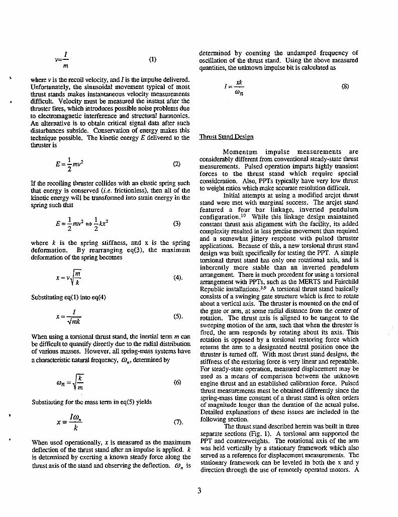
Verification of Impulm Measurements Figure 5 shows a chart recording of the thruststandresponse to the same pendulum strike. Prior to impact, the
The first series of tests with the thrust stand were thrust stand was perfectly at rest in its neutral position.performed to verify that momentum data derived using eq(8) When the impact occurred the thrust stand nearlywere accurately representing actual imparted values. This instantaneously accelerated to a finite velocity proportionalwas done by striking the thrust stand with an impact to the momentum absorbed. Thrust stand displacementpendulum. Momentum delivered by the pendulum was increased against a growing restoring force until acompared directly with the thrust standresponse, maximum amplitude was reached 3.4 seconds following
The impact pendulum consisted of a horizontal impact. At this point the velocity dropped to zero, and thealuminum rod 2.4 mm in diameter and 15 canin length. It restoring force drove the thrust stand in the oppositewas supported at each end by a nylon thread0.5 m in length direction. Since the spring-mass system of the thrust standand was free to swing horizontally in a direction parallel to was essentially frictionless, it continued to oscillate untilthe axis of the rod, as shown in Figure 3a. The suspended the electro-mechanical damper was activated. The thrustmass of the pendulum was determined using a precision stand returned to its neutral position approximately 4analytic balance and found to be 0.626 grams. The seconds after the damper was turned on. As can be seen,pendulum was suspended by a framework which aligned it displacement amplitude was symmetric in the positive andin front of the PPT such that the impact point was dead negative directions, and was repeatable until the dampercenter on the thruster. Since the impact tests were brought the system to rest. The maximum displacementperformed under vacuum conditions, the pendulum was used in eq(8) was measured as half the peak to peakmanipulated by a lever arrangement using a rotary amplitudeshown in the chart recording.feedthrough. The above procedurewas performed with pendulum
The instantaneous speed of the pendulum was strikes at four different magnitude levels, and the results ofmonitored by an optical arrangement, as was done similarly these are shown in Figure 6. This is a plot of impulsewith the PET._ A Ronchi ruling of 20 lines per cm was measured with the thrust stand as a function of momentumattached to the pendulum and oriented perpendicular to the delivered by the impact pendulum. The dotted line has apath of motion, as shown in Figure 3b. A second similar slope of 1, and represents an exact match. As can be seen,Ronchi ruling was positioned to overlap the fast but was the impulse values measured by the thrust stand were nearlyattached to the stationary structure. As the two rulings identical to those delivered by the pendulum, from themoved relative to one another, the adjacent line patterns smallest impulse bit of 85 /.tN-s to a maximum of 412created an optical chopping effect which corresponded with /2N-s. The results presented in Figure 6 suggest thatperiods of exact superposition and staggered overlap. Thischopperfrequency was monitoredby placingan incandescent thrust stand deflection measurements combined with eq(8)should accurately determine individual PPT impulse bitslamp and photo transistor on opposit_ sides of the adjacentrulings. As the pendulum swung down to impact the over the range in which they commonly occur. Noempirical correction factors were required. The largestthruster, it cut through the optical path between the lamp contribution to overall uncertainty resides in the ability toand the photo transistor. The output signal from the photo determine thrust stand displacement. In most cases this istransistor was recorded on a digital oscilloscope throughout within 1 percent of the measured value.the impact. The signal wave length was used to determinethe chopper frequency. This frequency multiplied by theruling line width determined the incoming and rebound PPT Single Shot Onerati0nspeeds of the pendulum
Figure 4 shows an oscilloscope trace of a typical The LES-8/9 thruster was first run in a single shotpendulum impact. The sine wave on the left side of the mode to determine the impulse bit of individual pulses.trace represents the optical interrupt signal of the incoming Tests were performed in a 1.5 m diameter by 5 m longpendulum immediately prior to impact. The frequencywas615 Hz, corresponding to a velocity of 0.312 m/s. At the vacuum facility 1° at an ambient background pressure of
approximately 2 x 10.3 Pa (1.5 x 10-s ton-). All single' center of the trace the pendulum underwenta partially elastic pulse momentum measurements were obtained by observingcollision with the thrust stand. The pendulum changed
direction and retraced its path at a reduced speed. The the thrust stand displacement with the damper disengaged.• rebound frequency of the optical signal was 325 Hz, Proceduresfor operating the thrust standand data acquisition
corresponding to a velocity of 0.165 m/s. The smaller equipment were identical to those used when testing withamplitude of the incoming signal was believed to be caused the impact pendulum. The thruster was provided with 28.0by a poor electrical response of the photo transistor circuit V across the main input terminals using a laboratory powersupply. A single PPT discharge could be obtained byat higher frequenciesand should not affect the velocitydata. applying a momentary ground signal on the control input
5

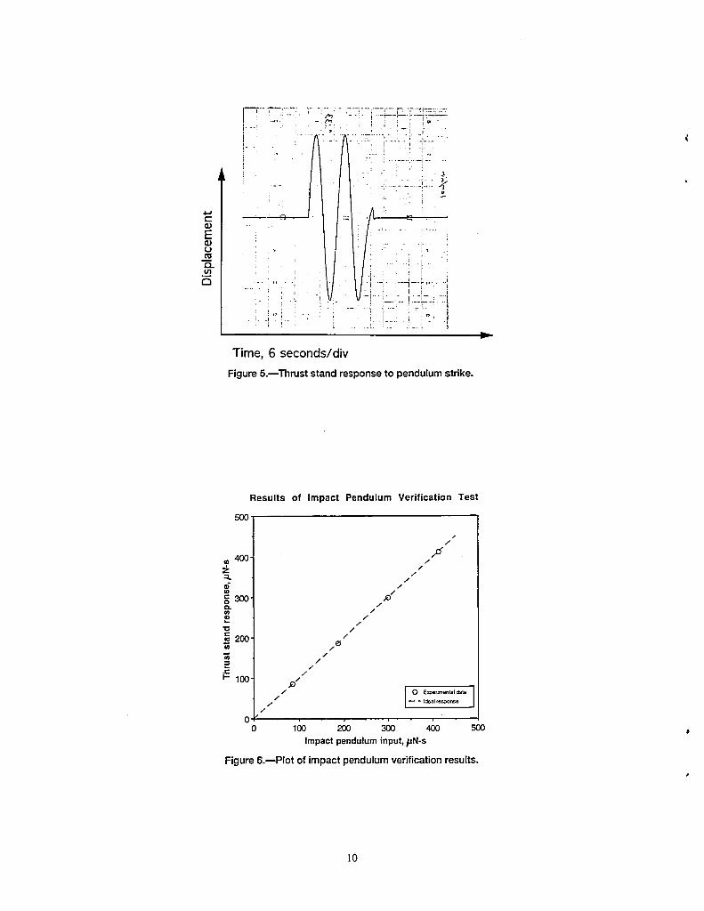
terminal. Figure 7 shows the thrust stand displacement only to velocity and not position, it resisted motion equallysignal resulting from a series of PPT single shot pulses, in both directions. The time average force imposed on thespaced about 45 seconds apart. Each trace began with the thruststand by the damper is zero,and so steady-state forcethrust stand at rest and the damper off. Once the thruster measurementswere not affected.ftred, the thruststand almost instantaneouslyaccelerated to a The LES-8/9 thruster was tested in repetitivefinite velocity determined by the mass of the thruster and mode by maintaining a constant ground signal on thethe impulse bit delivered by the PPT. Displacement control input terminal. When this was done, the thrusterincreased almost linearly with time, then gradually leveled automatically fired at about 2 Hz until the control signalof as the restoring force from the thruststand decelerated the was removed. Figure 9 shows a thrust signal of the PPTthruster. At the point of maximum displacement the during repetitive pulsed operation. Before the thruster wasthrustercame to a complete stop and then reversed direction activated the thrust stand was calibrated by cycling thetowards the thrust stand neutral position. Since there was weights as was done for Figure 2. When turned on, theno frictional damping the thruster overshot the neutral initial thruster pulse pushed the thrust stand in the positiveposition resulting in a sinusoidal oscillation until the directionfollowed by a very brief coasting movement. Eachelectromechanicaldamper was activated. When damped,the successive pulse pushed the thrust stand fartheraway fromthrust stand quickly returned to its neutral position in its neutral position as the restoring force began to pull inpreparation for the next pulse. As with the impact the opposite direction. After a period of time comparable topendulum tests, maximum displacement was measured as the natural time constant of the thrust stand, an equilibriumhalf the peak to peak movement of the thrust stand resulting position was reached. Pulse induced fluctuations of thefrom the pulse. At the end of the trace in Figure 7 is a thrust stand were typically about 1 percent of the steady-calibration resulting from a 250/2 N weight pulling along state value. Pulse frequency was counted at various pointsthe thrust axis. throughout the test run and found to be consistently 132 per
Since the LES-8/9 thruster uses two discharge minute. Irregular performance of the thruster resulted inports fh'ing at 30 degrees to the mounting plane, all sporadic excursions of the thrust signal which wereperformance data was adjusted for the cosine loss resulting typically several seconds in duration. These excursions arefrom an off-axis firing. Figure 8 is a plot of sequentially clearly visible in the thrust signal and result in variations ofmeasured impulse bits obtained from the PPT and corrected as much as 10 percent the average steady-state value.for a 30 degree off axis thrust vector. The apparently Average thrust was measured to be approximately 496/2 Nrandom variation in performance is believed to be real. The during the entire 30 minutes of operation. When taking thefact that the discharge plume was visibly different from thrust vector loss into account, this translated to a thrust ofpulse to pulse provided some evidence of this. The average 573 /2N along the axis of the discharge port. It isimpulse bit obtained in the test sequence was 266 /2 N-s. noteworthy that this value did not increase or decreaseThis value was slightly less than the 300 /2N-s published appreciably over the course of the test. When the thrusteras nominal performance for this device. H At the time of was turned off the thrust signal immediately dropped butinstallation there was noticeable soot on the insulators and was slowed in decent by the damper, resulting in a slightcarbon scale on the electrodes. This may have resulted in overshoot. After several seconds the thrust zero returnedpoor current distribution within the discharge and could very nearly to its original position, with less than 1 percentexplain theperformancedifference, positive drift. It may be noted that the zero drift observed
after actual thruster operation was in the positive directionwhile the drift observed during electrical flexure shunt tests
PPT RepetitiveOr_ration was in the negative direction. The current drawn by the- - PPT duringrepetitive operation averaged 1.75 A, which wasThe thrust stand was used to determine the time less than the 3 A used in the flexure test. Clearly there are
averaged thrust of the PPT operated in repetitive mode. other mechanisms than just input current which influencedThis was possible because the thruster firing repetition rate the drift of the thrust signal. The consequence of zero driftwas about 30 times the natural frequency of the thrust stand, was that it added uncertainty to thrust measurements takenSince the thrust stand response time was very long mid-way through the test run. Measurements taken at thecompared to the pulse repetition rate, it effectively averaged beginningor end were consideredmore accurate because theythe continuous string of impulse bits into a uniform thrust occurredimmediatelyafter or before a recent thrust zero, andforce. The restoring force of the thrust stand increased were easily corrected. Since there was no more than 1linearly with distance from its neutral position, and percent zero drift during the course of this 30 minute test, it feventually balanced the average thrust of the PPT. As with is reasonable to assume that the uncertainty of thrustconventional steady-state thrusters, the thrust stand measurementstaken in the middlewas about 1 percent.displacement was compared with deflections produced by An important quantitative comparison can be made ,free hanging calibration weights as a means of quantifying between the results obtained from the single shot thrusterforce measurements. Further smoothing of the average operation with that obtained in repetitive mode. The totalthrust signal was obtained by using the electromechanical impulse exerted by the thruster during repetitive operationdamper described earlier. Since the damper was sensitive was determined by the average thrust integrated over time.

A thrust of 573 /2N for 30 minutes resulted in a total 3. Ebert, W.L., et aI., "Operational Nova Spacecraftdelivered impulse of 1.03 N-s. During this period, the Teflon Pulsed PlasmaThruster System," AIAA Paper89-thruster fired approximately 3960 times. Thus, the average 2497, July 1989.impulsebit per pulse was approximately 260//N-s. Thiscompares closely with an average single shot value of 266 4. Curran, F.M. and Callahan, L.,"The NASA On-/2N-s measured from individual pulses. A more qualitative board Propulsion Program," AIAA Paper 95-2379, July1995.
• comparison can be made by examining the time dependent
variations in PPT performance. The thrust excursions 5. Myers, R.M., "Electromagnetic Propulsion forobserved in Figure 8 during the repetitive operation were Spacecraft," AIAA Paper 93-1086, February 1993,consistent with the shot to shot variations seen in Figure 8. (NASA CR-191186).While there appeared to be localized patterns during the
excursions rather than pure random variation, a larger 6. Stark, K.W.,et al.,"Design and Development of asample of single shot pulses may be required to identify Micropound Extended Range Thrust Stand (MERTS),"similar statistical groupings. NASA TN D-7029, August 1971.
7. Solbes, A. and Vondra R. J., "Performance StudyConclusions of a Solid Fuel-Pulsed Electric Microthruster," _100rnalof
A torsional type thrust stand has recently been Spacecraft and Rockets, Vol. 10, No. 6, June 1973,built for the purpose of testing PPTs in both single shot pp.406-410.
and repetitive operating modes. Momentum per pulse was 8. Burton, R.L., et al., "Investigation of a Pulseddetermined strictly as a function of thrust stand deflection, Electrothermal Thruster system," Report No. NASA CR-spring stiffness, and natural frequency. No empirical 174768,October 1984.corrections were needed. The accuracy of this method wasverified using a swinging impact pendulum. Momentum 9. Thrust Stand Operatons Manual, Fairchildtransferdata between the thruststandand the pendulumwere Republic Company, November 1976.consistent to within 1 percent.
A LES-8/9 PPT was tested on the thrust stand. It 10. Haag, T.W. and Curran, F.M., "Arcjet Startinghad a mass of approximately 7.5 kg, with a nominal thrust Reliability: A Multistart Test on Hydrogen/Nitrogento weight ratio of 1.3 x 10"5. A total of 34 single shot Mixtures," AIAA Paper 87-1061, May 1987, (NASAthruster pulses were individually measured. The average TM-89867).impulse bit per pulse was 266 12N-s, which was less than
the value of 300 /!N-s published in previous reports on 11. Vondra, R.J. and Thomassen, K.I., "Flightthis device. Qualified PulsedElectric Thruster for Satellite Control,"
Repetitivepulse measurements were performed in a Journal of Spacecraft and Rockets, Vol.11, No.9,way similar to ordinary steady-state thrust measurements. September 1974, pp. 613 - 617.The thrusterwas operated for30 minutes at a repetition rateof 132 pulses per minute and yielded an average thrust of573 ].tN. Based on thrust measurements, the averageimpulse bit per pulse was estimated to be 260/2 N-s. Zerodrift after this time was found to be about 1percent of themeasuredthrust.
References
1. Guman, W.J., "Pulsed Plasma Technology inMicrothrusters," AFAPL-TR-68-132, Fairchild Hiller
' Corp./RepublicAviation Division, November 1968.
2. Brill,Y., et al., "The Flight Application of a, Pulsed Plasma Microthruster; The NOVA Satellite,"
AIAAPaper 82-1956, November 1982.

Figure1.nPhotographof thruststand.
............... _-7_.;._----7_. _ -7L._C$...... _ .........
.o .
a
Time, 60 seconds/div
Figure 2.--Thrust stand displacement duringcalibrationcycle.

_ _. -_ Suspensionthreads_,. __-'_ -- Thruster
t_ _ _J _--Optical " face/ ruling _JJPendulumrod --_
\\
1Impact ,.site _"
(a)
Thruster
12V +r-_ face,_ Incandescent
"" lampPendulum
rod -_ Moving
I' '_ ruling--,
J \_"-Stationary
Phototransistor_,,._ ruling
_ _v_ _ t " _=_>_o_,_,,_,o_o,,,oooo_eFigure 3.mDiagram of impact pendulum.(a)Side view. (b)Top view.
Figure4.----Outputsignalfromphototransistorduringpendulumstrike.Timescale(1.33!_s/div).
i ..... _ _ i : ; I =
i "i.........i
i , • w ,
; i • I l i
!L .............
p.
Time, 6 seconds/div
Figure5.--Thrust standresponseto pendulumstrike.
Results of Impact Pendulum Verification Test
500.
/
400" /=' /s- /
o=30o• H/
Q- /
=-. /"O /
=c 200 ,,_/.q
•£: /
i- 100. j_/
/ / -- - Idealresponse/
0 •
o I_o 2_o _o _ sooImpactpenduluminput,pN-s
Figure 6.--Plot of impact pendulumverificationresults.
]0

........._J_b-fi- I....... r -i- -': " i.... .'--I -[ -fi-_ -: -;-fi..... t -! H-,-l---; - --q......... 4-- __'__rl
." i .... I --t-- -' .... . :....................... ;-:'-,"-,--
:":- -: " ; ......... '.......... ! '• .-r ;_ "i , _-t-;71
'_ hi ; " " -t-" / "_.) i
U " \i ._ _
. J._ __l--a !-..i--". .... L .... _ .t_..
• - t_j-,q .
'-i' i l : ---I- : ,--_-__,! _.s !" ' , r-.-i.z.... • ....... --i--_-
Time, 6 seconds/div
Figure 7.--Thrust stand response to series of PPT pulses.
Individual Pulse Measurements(corrected for thrust vector)
250'
_ 200'
o 15oIZE-- 100
5O
t 00 10 2o 3o 4o
Pulsecount
Figure 8.--Momentum measurements of individual PPT pulses.4
11
I . . I . . , . . . . - . . - . :i ' ! . i.. i , , I
-. . I . . . . . . . . . . . . . . . . . . . . , , .
? I 4 > - ! [ . , : -
.. . . . . . . . -, - -. I . '
, ' . . . . . ; ,.-: , , . ; ., . - , .-
I . m
Time, 60 seconds /div Figure 9.-Average thrust of PPT at 132 pulses/minute.
Form ApprovedREPORT DOCUMENTATION PAGE OMBNo.0704-0188
Public reportingburden for this collectionof informationis estimatedto average 1 hour per response, includingthe time for reviewing instructions,searchingexisting data sources,gathering and maintainingthe data needed, and completing and reviewingthe conectionof information. Send commentsregardingthis burdenestimateof any other aspect of thiscollectionof information,includingsuggestionsfor reducingthis burden,to Washington HeadquartersServices,Directoratefor InformationOperationsand Reports, 1215 JeffersonDavis Highway, Suite 1204, Arlington,VA 22202-4302. and to the Office of Managementand Budget, PaperworkReduction Project(0704-0188), Washington,DC 20503.
1. AGENCY USE ONLY (Leave blank) 2. REPORT DATE 3. REPORT TYPE AND DATES COVEREDNovember 1995 Technical Memorandum
4. TITLE AND SUBTITLE 5. FUNDING NUMBERSL
PPT Thrust Stand
WU-242-70--026. AUTHOR(S) v
Thomas W. Haag
7. PERFORMING ORGANIZATION NAME(S) AND ADDRESS(ES) 8. PERFORMING ORGANIZATIONREPORT NUMBER
National Aeronautics and Space AdministrationLewis Research Center E-9927Cleveland, Ohio 44135-3191
9. SPONSORING/MONITORING AGENCY NAME(S) AND ADDRESS(ES) 10. SPONSORING/MONITORINGAGENCY REPORT NUMBER
National Aeronautics and SpaceAdministration NASA TM-107066Washington,D.C. 20546-0001 AIAA-95-2917
11. SUPPLEMENTARY NOTES
Prepared for the 31st Joint Propulsion Conferenceand Exhibit cosponsored by AIAA, ASME, SAE, and ASEE, SanDiego, California, July 10-12, 1995. Responsible person, Thomas W.Haag, organizationcode 5330, (216) 977-7423.
12a. DISTRIBUTION/AVAILABILITY STATEMENT 12b. DISTRIBUTION CODE
Unclassified-Unlimited
Subject Category 20
This publication is available from the NASA Center for Aerospace Information, (301) 621-0390.13. ABSTRACT (Maximum 200 words)
Atorsional-type thrust stand has been designed and built to test Pulsed PlasmaThrusters (PPTs)in both single shot andrepetitive operatingmodes. Using this stand, momentum per pulse was determined strictly as a function of thrust standdeflection, springconstant, and natural frequency. No empirical corrections were required. The accuracy of the methodwas verified using a swinging impact pendulum. Momentum transfer data between the thrust stand and the pendulumwere consistent to within 1 percent. Following initial calibrations, the stand was used to test a Lincoln ExperimentalSatellite (LES-8/9) thruster. The LES-8/9 systemhad a mass of approximately7.5 kg, witha nominal thrust to weightratio of 1.3x10⁻⁵. A total of 34 single shot thruster pulses were individually measured. The average impulse bit per pulsewas 266 AtN-s, which was slightly less than the value of 300 AtN-s published in previous reports on this device. Repeti-tive pulse measurements were performed similar to ordinary steady-state thrust measurements. The thruster was operatedfor 30 minutes at a repetition rate of 132pulses per minuteand yielded an average thrust of 573AtN. Using averagethrust, the average impulse bit per pulse was estimated to be 260 AtN-s, which was in ageement with the single shot data.Zero drift during the repetitive pulse test was found to be approximately 1 percent of the measuredthrust.
14. SUBJECT TERMS 15. NUMBER OF PAGES14
Pulsed plasma; Electromagnetic; Propulsion is. PRICECODEA03
17. SECURITY CLASSIFICATION 18. SECURITY CLASSIFICATION 19. SECURITYCLASSIFICATION 20. LIMITATION OF AB_5/HACTOF REPORT OF THIS PAGE OF ABSTRACT
Unclassified Unclassified Unclassified
NSN 7540-01-280-5500 Standard Form 298 (Rev. 2-89)Prescribed by ANSI Std. Z39-18298-102