Powerware Energy Management System (EMS) Upgrade Kit (208
72
Powerware Energy Management System (EMS) Upgrade Kit (208/120V, 380/220V, 400/230V, 415/240V) User’s Guide ®
Transcript of Powerware Energy Management System (EMS) Upgrade Kit (208
Powerware Energy Management System (EMS)Upgrade Kit (208/120V, 380/220V, 400/230V, 415/240V)User’s Guide
®

Requesting a Declaration of ConformityUnits that are labeled with a CE mark comply with the following harmonized standards and EU directives:
� Harmonized Standard: IEC 61010−1:2001−02
� EU Directives: 2006/95/EC, Council Directive on equipment designed for use within certain voltage limits
2004/108/EC, Council Directive relating to electromagnetic compatibility
The EC Declaration of Conformity is available upon request for products with a CE mark. For copies of the EC
Declaration of Conformity, contact:
Eaton Power Quality Oy
Koskelontie 13
FIN−02920 Espoo
Finland
Phone: +358−9−452 661
Fax: +358−9−452 665 68
Eaton, Powerware, Power Xpert, and X−Slot are registered trademarks of Eaton Corporation or its subsidiaries and
affiliates. HyperTerminal is a registered trademark of Hilgraeve. Kirk is a registered trademark of the Kirk Key
Interlock Company. Microsoft and Windows are registered trademarks of Microsoft Corporation in the United States
and/or other countries. Modbus is a registered trademark of Schneider Electric. National Electrical Code and NEC are
registered trademarks of National Fire Protection Association, Inc. Phillips is a registered trademark of Phillips Screw
Company. All other trademarks are property of their respective companies.
�Copyright 2008 Eaton Corporation, Raleigh, NC, USA. All rights reserved. No part of this document may be
reproduced in any way without the express written approval of Eaton Corporation.
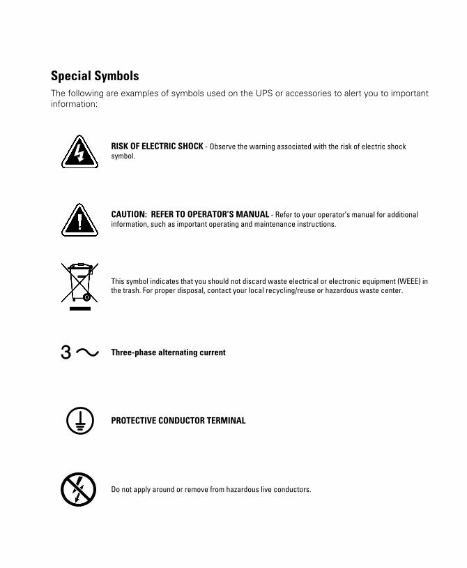
Special SymbolsThe following are examples of symbols used on the UPS or accessories to alert you to important
information:
RISK OF ELECTRIC SHOCK − Observe the warning associated with the risk of electric shock
symbol.
CAUTION: REFER TO OPERATOR’S MANUAL − Refer to your operator’s manual for additional
information, such as important operating and maintenance instructions.
This symbol indicates that you should not discard waste electrical or electronic equipment (WEEE) inthe trash. For proper disposal, contact your local recycling/reuse or hazardous waste center.
Three−phase alternating current
PROTECTIVE CONDUCTOR TERMINAL
Do not apply around or remove from hazardous live conductors.

EATON Powerware® Energy Management System (EMS) Upgrade Kit User’s Guide � 164201724 Rev 1 www.powerware.com i
Table of Contents
1 Introduction 1. . . . . . . . . . . . . . . . . . . . . . . . . . . . . . . . . . . . . . . . . . . . . . . . . . . . . . . . .
Safety Warnings 3. . . . . . . . . . . . . . . . . . . . . . . . . . . . . . . . . . . . . . . . . . . . . . . . . . . . . . . . . . . . . . . . . . . . .
2 Installation 7. . . . . . . . . . . . . . . . . . . . . . . . . . . . . . . . . . . . . . . . . . . . . . . . . . . . . . . . . .
Inspecting the Equipment 7. . . . . . . . . . . . . . . . . . . . . . . . . . . . . . . . . . . . . . . . . . . . . . . . . . . . . . . . . . . . . . .
Unpacking the Cabinet 7. . . . . . . . . . . . . . . . . . . . . . . . . . . . . . . . . . . . . . . . . . . . . . . . . . . . . . . . . . . . . . . . .
Checking the Parts List 8. . . . . . . . . . . . . . . . . . . . . . . . . . . . . . . . . . . . . . . . . . . . . . . . . . . . . . . . . . . . . . . . .
Tools Required 9. . . . . . . . . . . . . . . . . . . . . . . . . . . . . . . . . . . . . . . . . . . . . . . . . . . . . . . . . . . . . . . . . . . . . .
Installing the Hardware 10. . . . . . . . . . . . . . . . . . . . . . . . . . . . . . . . . . . . . . . . . . . . . . . . . . . . . . . . . . . . . . . .
Electrical Connections 13. . . . . . . . . . . . . . . . . . . . . . . . . . . . . . . . . . . . . . . . . . . . . . . . . . . . . . . . . . . . . . . . .
Initial Configuration 25. . . . . . . . . . . . . . . . . . . . . . . . . . . . . . . . . . . . . . . . . . . . . . . . . . . . . . . . . . . . . . . . . . .
Installing the Software Configuration Tool 25. . . . . . . . . . . . . . . . . . . . . . . . . . . . . . . . . . . . . . . . . . . . . . . .
Initial System Configuration 26. . . . . . . . . . . . . . . . . . . . . . . . . . . . . . . . . . . . . . . . . . . . . . . . . . . . . . . . . .
Initial Panel and Breaker Configuration (Using the Software Configuration Tool) 31. . . . . . . . . . . . . . . . . . . . . .
Initial Panel and Breaker Configuration (Using the Display) 34. . . . . . . . . . . . . . . . . . . . . . . . . . . . . . . . . . . . .
Advanced Metering Installation 36. . . . . . . . . . . . . . . . . . . . . . . . . . . . . . . . . . . . . . . . . . . . . . . . . . . . . . . . . .
3 Operation 37. . . . . . . . . . . . . . . . . . . . . . . . . . . . . . . . . . . . . . . . . . . . . . . . . . . . . . . . . . .
Reset Function 37. . . . . . . . . . . . . . . . . . . . . . . . . . . . . . . . . . . . . . . . . . . . . . . . . . . . . . . . . . . . . . . . . . . . . .
Breaker Numbering 37. . . . . . . . . . . . . . . . . . . . . . . . . . . . . . . . . . . . . . . . . . . . . . . . . . . . . . . . . . . . . . . . . . .
Control Panel Functions 38. . . . . . . . . . . . . . . . . . . . . . . . . . . . . . . . . . . . . . . . . . . . . . . . . . . . . . . . . . . . . . . .
Display Functions 39. . . . . . . . . . . . . . . . . . . . . . . . . . . . . . . . . . . . . . . . . . . . . . . . . . . . . . . . . . . . . . . . . .
Menu Map 40. . . . . . . . . . . . . . . . . . . . . . . . . . . . . . . . . . . . . . . . . . . . . . . . . . . . . . . . . . . . . . . . . . . . . .
Setup Options 42. . . . . . . . . . . . . . . . . . . . . . . . . . . . . . . . . . . . . . . . . . . . . . . . . . . . . . . . . . . . . . . . . . . .
Control Panel Configuration 43. . . . . . . . . . . . . . . . . . . . . . . . . . . . . . . . . . . . . . . . . . . . . . . . . . . . . . . . . . . . .
Accessing Configuration 43. . . . . . . . . . . . . . . . . . . . . . . . . . . . . . . . . . . . . . . . . . . . . . . . . . . . . . . . . . . . .
Configuring Panels Containing Branch Circuit Breakers 43. . . . . . . . . . . . . . . . . . . . . . . . . . . . . . . . . . . . . . .
Configuring Panels Containing Subfeed Breakers 44. . . . . . . . . . . . . . . . . . . . . . . . . . . . . . . . . . . . . . . . . . . .
Configuring Branch Circuit Breakers 46. . . . . . . . . . . . . . . . . . . . . . . . . . . . . . . . . . . . . . . . . . . . . . . . . . . . .
Viewing Panel Meters 48. . . . . . . . . . . . . . . . . . . . . . . . . . . . . . . . . . . . . . . . . . . . . . . . . . . . . . . . . . . . . . . . .
Viewing Breaker Meters 48. . . . . . . . . . . . . . . . . . . . . . . . . . . . . . . . . . . . . . . . . . . . . . . . . . . . . . . . . . . . . . . .
TABLE OF CONTENTS
EATON Powerware® Energy Management System (EMS) Upgrade Kit User’s Guide � 164201724 Rev 1 www.powerware.comii
4 Communication 49. . . . . . . . . . . . . . . . . . . . . . . . . . . . . . . . . . . . . . . . . . . . . . . . . . . . . .
Installing Communication Features 50. . . . . . . . . . . . . . . . . . . . . . . . . . . . . . . . . . . . . . . . . . . . . . . . . . . . . . . .
Communication Options 50. . . . . . . . . . . . . . . . . . . . . . . . . . . . . . . . . . . . . . . . . . . . . . . . . . . . . . . . . . . . . . . .
Serial Port (Service) 50. . . . . . . . . . . . . . . . . . . . . . . . . . . . . . . . . . . . . . . . . . . . . . . . . . . . . . . . . . . . . . . .
X−Slot Card 51. . . . . . . . . . . . . . . . . . . . . . . . . . . . . . . . . . . . . . . . . . . . . . . . . . . . . . . . . . . . . . . . . . . . . .
Control Terminals 52. . . . . . . . . . . . . . . . . . . . . . . . . . . . . . . . . . . . . . . . . . . . . . . . . . . . . . . . . . . . . . . . . . . .
Relay Output Contacts (Alarm Relay) 53. . . . . . . . . . . . . . . . . . . . . . . . . . . . . . . . . . . . . . . . . . . . . . . . . . . .
Programmable Signal Inputs (Building Alarms) 53. . . . . . . . . . . . . . . . . . . . . . . . . . . . . . . . . . . . . . . . . . . . .
5 Maintenance 55. . . . . . . . . . . . . . . . . . . . . . . . . . . . . . . . . . . . . . . . . . . . . . . . . . . . . . . .
Recycling the Used Equipment 55. . . . . . . . . . . . . . . . . . . . . . . . . . . . . . . . . . . . . . . . . . . . . . . . . . . . . . . . . . .
Updating the Firmware 55. . . . . . . . . . . . . . . . . . . . . . . . . . . . . . . . . . . . . . . . . . . . . . . . . . . . . . . . . . . . . . . . .
Replacing the Power Xpert Gateway Series 1000 Card 55. . . . . . . . . . . . . . . . . . . . . . . . . . . . . . . . . . . . . . . . . .
Rewiring and Reconfiguring the Installation 56. . . . . . . . . . . . . . . . . . . . . . . . . . . . . . . . . . . . . . . . . . . . . . . . . .
6 Specifications 57. . . . . . . . . . . . . . . . . . . . . . . . . . . . . . . . . . . . . . . . . . . . . . . . . . . . . . .
7 Troubleshooting 61. . . . . . . . . . . . . . . . . . . . . . . . . . . . . . . . . . . . . . . . . . . . . . . . . . . . . .
Typical Alarms and Conditions 61. . . . . . . . . . . . . . . . . . . . . . . . . . . . . . . . . . . . . . . . . . . . . . . . . . . . . . . . . . .
Service and Support 61. . . . . . . . . . . . . . . . . . . . . . . . . . . . . . . . . . . . . . . . . . . . . . . . . . . . . . . . . . . . . . . . . . .
8 Warranty 63. . . . . . . . . . . . . . . . . . . . . . . . . . . . . . . . . . . . . . . . . . . . . . . . . . . . . . . . . . .
Limited Factory Warranty 63. . . . . . . . . . . . . . . . . . . . . . . . . . . . . . . . . . . . . . . . . . . . . . . . . . . . . . . . . . . . . . .

EATON Powerware® Energy Management System (EMS) Upgrade Kit User’s Guide � 164201724 Rev 1 www.powerware.com 1
Chapter 1 Introduction
Eaton’s Powerware® Energy Management System (EMS) Upgrade Kit
(EMS−UGK) is designed to monitor energy usage of existing power
distribution panelboards, remote power panels, or power distribution
units. Providing outstanding performance and reliability, the EMS−UGK’s
unique benefits include the following:
� Monitors up to 42 (single panel) or 84 (dual panel) circuits in a
standard three−phase panelboard. Measures and stores energy
parameters for each of the individual monitored circuits, letting you
manage power with greater precision.
� Functions in a wide variety of applications supporting various data
center loads that may require a power distribution monitoring
solution, especially where power needs are changing and backup
architecture must be scalable.
� Can be mounted on a wall with the included mounting bracket and
customer−supplied fasteners appropriate for the type of wall.
� Choice of voltage sensing installation: connection to an unoccupied
circuit breaker using included transition harnesses or connection to an
occupied circuit breaker using included wire taps.
� Includes a software tool for easy configuring of settings and options.
� All harnesses supplied except for optional external ground.
� No preventive maintenance required other than verifying the
hardware and wiring are clear of debris. The EMS−UGK does not
require an annual calibration.
� Advanced Metering monitoring system, providing communication
options such as network connectivity through the Power Xpert®
Gateway Card installed in the X−Slot® communication bay.
� Intended for continuous duty operation.
� Backed by worldwide agency approvals.

INTRODUCTION
EATON Powerware® Energy Management System (EMS) Upgrade Kit User’s Guide � 164201724 Rev 1 www.powerware.com2
The following options for the EMS−UGK are available:
� Single panel (42 circuits) or dual panel (84 circuits)
� 208/120V or 380/220V, 400/230V, 415/240V rating
� Liquid crystal display (LCD) for local indication of energy usage
� Conduit box for enhanced harness protection
� Main input monitoring (three phases and one neutral rated to
measure currents up to 400A; up to 100A for input ground)
The following accessories for the EMS−UGK are available:
� Subfeed breaker monitoring, rated to measure currents up to 400A
� 100A branch circuit breaker monitoring
� Temperature and humidity monitoring with the optional
Environmental Monitoring Probe (EMP) that is used with the
Power Xpert Gateway Series 1000 Card installed in the EMS−UGK
The EMS−UGK includes an externally−mounted enclosure with an
optional display. Current transformers (CTs) provide branch circuit
monitoring of installed panelboards. Figure 1 shows an example
installation of an EMS−UGK.
Figure 1. Typical EMS−UGK Installation (Dual Panel Shown with Optional Display)

INTRODUCTION
EATON Powerware® Energy Management System (EMS) Upgrade Kit User’s Guide � 164201724 Rev 1 www.powerware.com 3
Safety Warnings
IMPORTANT SAFETY INSTRUCTIONSSAVE THESE INSTRUCTIONS
This manual contains important instructions that you should follow during installation andoperation of the EMS−UGK. Please read all instructions before operating the equipment andsave this manual for future reference.
D A N G E RThis EMS−UGK contains LETHAL VOLTAGES. All repairs and service should be performedby AUTHORIZED SERVICE PERSONNEL ONLY. There are NO USER SERVICEABLEPARTS inside the EMS−UGK.
C A U T I O N� To reduce the risk of fire or electric shock, install this EMS−UGK in a temperature and
humidity controlled, indoor environment, free of conductive contaminants. Ambienttemperature must not exceed 40°C (104°F). Do not operate near water or excessivehumidity (95% maximum).
� Use the branch circuit breakers to disconnect hazardous voltage from the EMS−UGK. Turnoff the breaker before disconnecting the voltage measuring circuit cables, or hazardousvoltage may be present at the exposed end of the cable.
� Installation or use of the equipment in a manner not specified by the manufacturer mayimpair the protection provided by the equipment.
INTRODUCTION
EATON Powerware® Energy Management System (EMS) Upgrade Kit User’s Guide � 164201724 Rev 1 www.powerware.com4
Consignes de sécurité
CONSIGNES DE SÉCURITÉ IMPORTANTESCONSERVER CES INSTRUCTIONS
Ce manuel contient des instructions importantes que vous êtes invité à suivre lors de touteprocédure d’installation et de fonctionnement de EMS−UGK. Veuillez consulter entièrementces instructions avant de faire fonctionner l’équipement et conserver ce manuel afin depouvoir vous y reporter ultérieurement.
D A N G E R !Cet EMS−UGK contient des TENSIONS MORTELLES. Toute opération d’entretien et deréparation doit être EXCLUSIVEMENT CONFIÉE A UN PERSONNEL QUALIFIÉ AGRÉÉ.AUCUNE PIÈCE RÉPARABLE PAR L’UTILISATEUR ne se trouve dans la EMS−UGK.
A T T E N T I O N !� Pour réduire les risques d’incendie et de décharge électrique, installer la EMS−UGK
uniquement à l’intérieur, dans un lieu dépourvu de matériaux conducteurs, où latempérature et l’humidité ambiantes sont contrôlées. La température ambiante ne doitpas dépasser 40 °C. Ne pas utiliser à proximité d’eau ou dans une atmosphèreexcessivement humide (95 % maximum).
INTRODUCTION
EATON Powerware® Energy Management System (EMS) Upgrade Kit User’s Guide � 164201724 Rev 1 www.powerware.com 5
Sicherheitswarnungen
WICHTIGE SICHERHEITSANWEISUNGENAUFBEWAREN
Dieses Handbuch enthält wichtige Hinweise, welche Sie bei der Installation und Wartungdes EMS−UGK beachten sollten. Bitte lesen Sie alle Anweisungen des Handbuches bevor siemit dem Gerät arbeiten. Bewaren Sie das Handbuch zum Nachlesen auf.
W A R N U N GDie EMS−UGK führt lebensgefährliche Spannungen. Alle Reparatur− und Wartungsarbeitensollten nur von Kundendienstfachleuten durchgeführt werden. Die EMS−UGK enthält keinevom Benutzer zu wartenden Komponenten.
A C H T U N G� Um die Brand- oder Elektroschockgefahr zu verringern, diese EMS−UGK nur in Gebäuden
mit kontrollierter Temperatur und Luftfeuchtigkeit installieren, in denen keine leitendenSchmutzstoffen vorhanden sind. Die Umgebungstemperatur darf 40°C nicht übersteigen.Die EMS−UGK nicht in der Nähe von Wasser oder in extrem hoher Luftfeuchtigkeit (max.95 %) betreiben.
INTRODUCTION
EATON Powerware® Energy Management System (EMS) Upgrade Kit User’s Guide � 164201724 Rev 1 www.powerware.com6
Advertencias de Seguridad
INSTRUCCIONES DE SEGURIDAD IMPORTANTESGUARDE ESTAS INSTRUCCIONES
Este manual contiene instrucciones importantes que debe seguir durante la instalación y elfuncionamiento de la EMS−UGK. Por favor, lea todas las instrucciones antes de poner enfuncionamiento el equipo y guarde este manual para referencia en el futuro.
P E L I G R OEste EMS−UGK contiene VOLTAJES MORTALES. Todas las reparaciones y el servicio técnicodeben ser efectuados SOLAMENTE POR PERSONAL DE SERVICIO TÉCNICO AUTORIZADO.No hay NINGUNA PARTE QUE EL USUARIO PUEDA REPARAR dentro de la EMS−UGK.
P R E C A U C I Ó N� Para reducir el riesgo de incendio o de choque eléctrico, instale este EMS−UGK en un
lugar cubierto, con temperatura y humedad controladas, libre de contaminantesconductores. La temperatura ambiente no debe exceder los 40°C. No trabaje cerca delagua o con humedad excesiva (95% máximo).

EATON Powerware® Energy Management System (EMS) Upgrade Kit User’s Guide � 164201724 Rev 1 www.powerware.com 7
Chapter 2 Installation
This section explains:
� Equipment inspection
� Unpacking
� Parts list
� Required tools
� Installation and wiring
� Initial configuration
� Advanced Metering installation
Inspecting the Equipment
If any equipment has been damaged during shipment, keep the shipping
cartons and packing materials for the carrier or place of purchase and file
a claim for shipping damage. If you discover damage after acceptance,
file a claim for concealed damage.
To file a claim for shipping damage or concealed damage: 1) File with
the carrier within 15 days of receipt of the equipment; 2) Send a copy of
the damage claim within 15 days to your service representative.
Unpacking the Cabinet
Use care when moving and opening the carton. Leave the components
packaged until ready to install.
To unpack the cabinet:
1. Open the outer carton and remove the items packaged with the
cabinet.
2. Carefully lift the cabinet out of the outer carton.
3. Discard or recycle the packaging in a responsible manner, or store it
for future use.
Place the cabinet in a protected area that has adequate airflow and is
free of humidity, flammable gas, and corrosion.
INSTALLATION
EATON Powerware® Energy Management System (EMS) Upgrade Kit User’s Guide � 164201724 Rev 1 www.powerware.com8
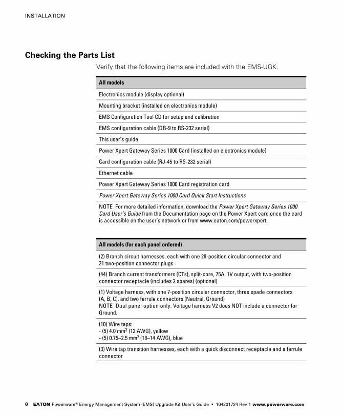
Checking the Parts List
Verify that the following items are included with the EMS−UGK.
All models
Electronics module (display optional)
Mounting bracket (installed on electronics module)
EMS Configuration Tool CD for setup and calibration
EMS configuration cable (DB−9 to RS−232 serial)
This user’s guide
Power Xpert Gateway Series 1000 Card (installed on electronics module)
Card configuration cable (RJ−45 to RS−232 serial)
Ethernet cable
Power Xpert Gateway Series 1000 Card registration card
Power Xpert Gateway Series 1000 Card Quick Start Instructions
NOTE For more detailed information, download the Power Xpert Gateway Series 1000
Card User’s Guide from the Documentation page on the Power Xpert card once the card
is accessible on the user’s network or from www.eaton.com/powerxpert.
All models (for each panel ordered)
(2) Branch circuit harnesses, each with one 28−position circular connector and
21 two−position connector plugs
(44) Branch current transformers (CTs), split−core, 75A, 1V output, with two−position
connector receptacle (includes 2 spares) (optional)
(1) Voltage harness, with one 7−position circular connector, three spade connectors
(A, B, C), and two ferrule connectors (Neutral, Ground)
NOTE Dual panel option only. Voltage harness V2 does NOT include a connector for
Ground.
(10) Wire taps:
− (5) 4.0 mm2 (12 AWG), yellow
− (5) 0.75–2.5 mm2 (18–14 AWG), blue
(3) Wire tap transition harnesses, each with a quick disconnect receptacle and a ferrule
connector
INSTALLATION
EATON Powerware® Energy Management System (EMS) Upgrade Kit User’s Guide � 164201724 Rev 1 www.powerware.com 9
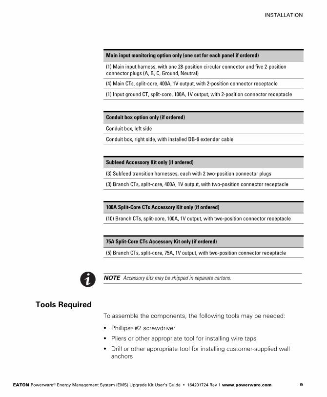
Main input monitoring option only (one set for each panel if ordered)
(1) Main input harness, with one 28−position circular connector and five 2−position
connector plugs (A, B, C, Ground, Neutral)
(4) Main CTs, split−core, 400A, 1V output, with 2−position connector receptacle
(1) Input ground CT, split−core, 100A, 1V output, with 2−position connector receptacle
Conduit box option only (if ordered)
Conduit box, left side
Conduit box, right side, with installed DB−9 extender cable
Subfeed Accessory Kit only (if ordered)
(3) Subfeed transition harnesses, each with 2 two−position connector plugs
(3) Branch CTs, split−core, 400A, 1V output, with two−position connector receptacle
100A Split−Core CTs Accessory Kit only (if ordered)
(10) Branch CTs, split−core, 100A, 1V output, with two−position connector receptacle
75A Split−Core CTs Accessory Kit only (if ordered)
(5) Branch CTs, split−core, 75A, 1V output, with two−position connector receptacle
NOTE Accessory kits may be shipped in separate cartons.
Tools Required
To assemble the components, the following tools may be needed:
� Phillips® #2 screwdriver
� Pliers or other appropriate tool for installing wire taps
� Drill or other appropriate tool for installing customer−supplied wall
anchors

INSTALLATION
EATON Powerware® Energy Management System (EMS) Upgrade Kit User’s Guide � 164201724 Rev 1 www.powerware.com10
Installing the Hardware
NOTE Review the wiring planning requirements in Step 3 on page 14 as an aid to locating
an appropriate site for the EMS−UGK.
To install the EMS−UGK on a wall:
1. Verify that the wall on which the EMS−UGK is to be mounted meets
the recommendations listed in Table 1.
Table 1. Wall Specifications (Customer−Supplied Components)
Component Specification
Wall surface and
wall anchors
Sufficient to support the weight of the EMS−UGK and installed
cables (see Table 12 on page 57 for weight specifications)
Clearance around
electronics module
Above: 102 mm (4") [152 mm (6") recommended]
Below: 102 mm (4")
Sides: 152 mm (6")
2. Loosen the four front screws, and remove the four rear screws.
Remove the mounting bracket from the electronics module. Retain
the bracket and four removed screws. See Figure 2.
M4�10 screws(8 places)
Figure 2. Mounting Bracket and Electronics Module (with Optional Display)
INSTALLATION
EATON Powerware® Energy Management System (EMS) Upgrade Kit User’s Guide � 164201724 Rev 1 www.powerware.com 11
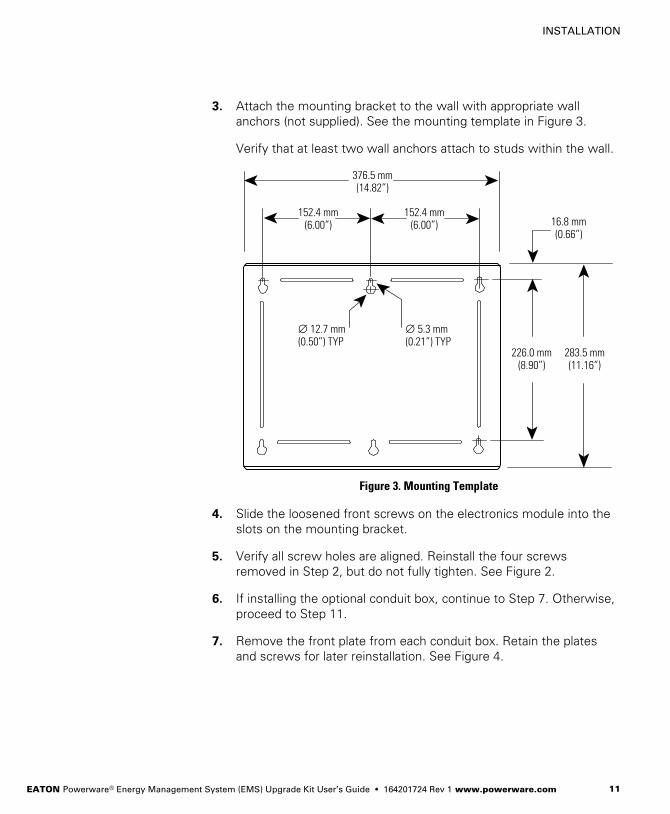
3. Attach the mounting bracket to the wall with appropriate wall
anchors (not supplied). See the mounting template in Figure 3.
Verify that at least two wall anchors attach to studs within the wall.
376.5 mm(14.82")
152.4 mm(6.00")
152.4 mm(6.00")
226.0 mm(8.90")
283.5 mm(11.16")
16.8 mm(0.66")
∅ 12.7 mm(0.50") TYP
∅ 5.3 mm(0.21") TYP
Figure 3. Mounting Template
4. Slide the loosened front screws on the electronics module into the
slots on the mounting bracket.
5. Verify all screw holes are aligned. Reinstall the four screws
removed in Step 2, but do not fully tighten. See Figure 2.
6. If installing the optional conduit box, continue to Step 7. Otherwise,
proceed to Step 11.
7. Remove the front plate from each conduit box. Retain the plates
and screws for later reinstallation. See Figure 4.
INSTALLATION
EATON Powerware® Energy Management System (EMS) Upgrade Kit User’s Guide � 164201724 Rev 1 www.powerware.com12
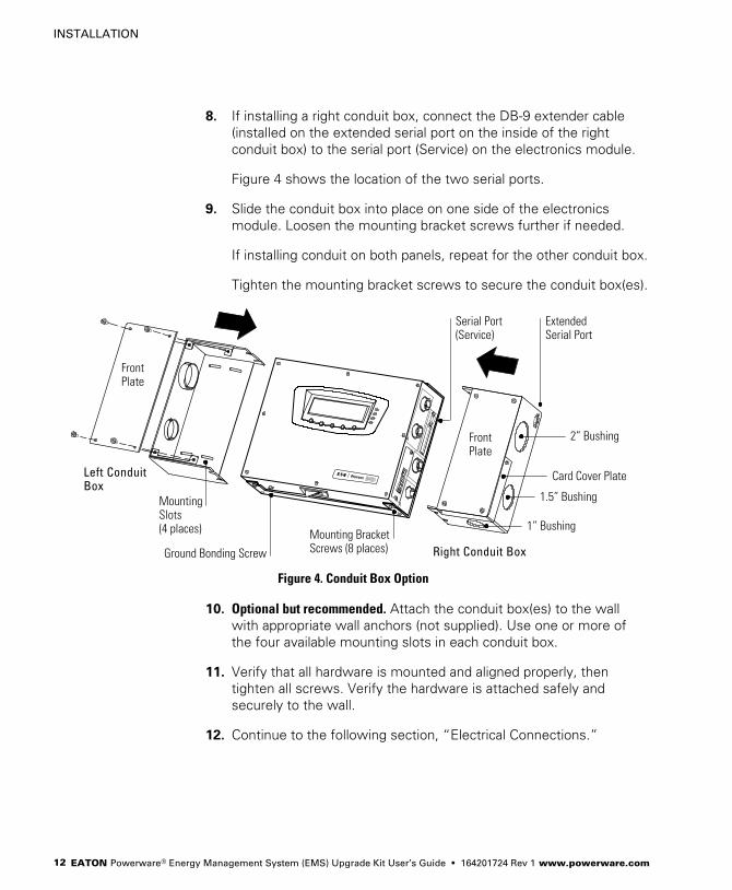
8. If installing a right conduit box, connect the DB−9 extender cable
(installed on the extended serial port on the inside of the right
conduit box) to the serial port (Service) on the electronics module.
Figure 4 shows the location of the two serial ports.
9. Slide the conduit box into place on one side of the electronics
module. Loosen the mounting bracket screws further if needed.
If installing conduit on both panels, repeat for the other conduit box.
Tighten the mounting bracket screws to secure the conduit box(es).
Left ConduitBox
FrontPlate
FrontPlate
MountingSlots(4 places)
Serial Port(Service)
ExtendedSerial Port
Card Cover Plate
Mounting BracketScrews (8 places)Ground Bonding Screw
2" Bushing
1.5" Bushing
1" Bushing
Right Conduit Box
Figure 4. Conduit Box Option
10. Optional but recommended. Attach the conduit box(es) to the wall
with appropriate wall anchors (not supplied). Use one or more of
the four available mounting slots in each conduit box.
11. Verify that all hardware is mounted and aligned properly, then
tighten all screws. Verify the hardware is attached safely and
securely to the wall.
12. Continue to the following section, �Electrical Connections."

INSTALLATION
EATON Powerware® Energy Management System (EMS) Upgrade Kit User’s Guide � 164201724 Rev 1 www.powerware.com 13
Electrical Connections
W A R N I N G� Only qualified service personnel (such as a licensed electrician) shall perform the
electrical installation. Risk of electrical shock.
� Always follow all personal protective equipment (PPE) and other safety rules whenworking around electricity.
C A U T I O N� Use the branch circuit breakers to disconnect hazardous voltage from the EMS−UGK. Turn
off the breaker before disconnecting the voltage measuring circuit cables, or hazardousvoltage may be present at the exposed end of the cable.
� To prevent mechanical damage, coil and secure any excess cable away from the floor.
The EMS−UGK is designed for quick and easy installation. Labels on the
harnesses describe where to connect the CTs and wire taps. Keyed
circular connectors provide a quick and secure installation to the
electronics module.
To connect the wiring for the EMS−UGK:
C A U T I O NBefore wiring the EMS−UGK, disconnect the load and shut down the host equipment. Referto the user’s guide for the host equipment for shutdown instructions.
1. Verify that no circuits on which the EMS−UGK will be installed are
energized. Be absolutely sure there is no power.
2. Optional. Connect the ground cable (not supplied) from the host
equipment to the M5 ground bonding screw on the bottom of the
electronics module. Figure 4 shows the location of the ground
bonding screw.
INSTALLATION
EATON Powerware® Energy Management System (EMS) Upgrade Kit User’s Guide � 164201724 Rev 1 www.powerware.com14
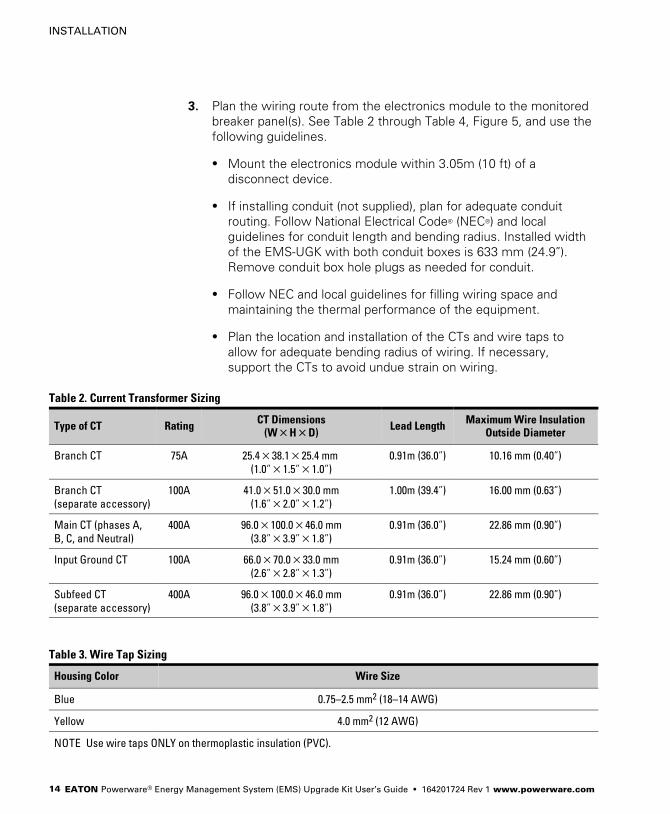
3. Plan the wiring route from the electronics module to the monitored
breaker panel(s). See Table 2 through Table 4, Figure 5, and use the
following guidelines.
� Mount the electronics module within 3.05m (10 ft) of a
disconnect device.
� If installing conduit (not supplied), plan for adequate conduit
routing. Follow National Electrical Code® (NEC®) and local
guidelines for conduit length and bending radius. Installed width
of the EMS−UGK with both conduit boxes is 633 mm (24.9").Remove conduit box hole plugs as needed for conduit.
� Follow NEC and local guidelines for filling wiring space and
maintaining the thermal performance of the equipment.
� Plan the location and installation of the CTs and wire taps to
allow for adequate bending radius of wiring. If necessary,
support the CTs to avoid undue strain on wiring.
Table 2. Current Transformer Sizing
Type of CT Rating CT Dimensions(W�H�D)
Lead Length Maximum Wire InsulationOutside Diameter
Branch CT 75A 25.4�38.1�25.4 mm
(1.0"�1.5"�1.0")
0.91m (36.0") 10.16 mm (0.40")
Branch CT
(separate accessory)
100A 41.0�51.0�30.0 mm
(1.6"�2.0"�1.2")
1.00m (39.4") 16.00 mm (0.63")
Main CT (phases A,
B, C, and Neutral)
400A 96.0�100.0�46.0 mm
(3.8"�3.9"�1.8")
0.91m (36.0") 22.86 mm (0.90")
Input Ground CT 100A 66.0�70.0�33.0 mm
(2.6"�2.8"�1.3")
0.91m (36.0") 15.24 mm (0.60")
Subfeed CT
(separate accessory)
400A 96.0�100.0�46.0 mm
(3.8"�3.9"�1.8")
0.91m (36.0") 22.86 mm (0.90")
Table 3. Wire Tap Sizing
Housing Color Wire Size
Blue 0.75–2.5 mm2 (18–14 AWG)
Yellow 4.0 mm2 (12 AWG)
NOTE Use wire taps ONLY on thermoplastic insulation (PVC).
INSTALLATION
EATON Powerware® Energy Management System (EMS) Upgrade Kit User’s Guide � 164201724 Rev 1 www.powerware.com 15
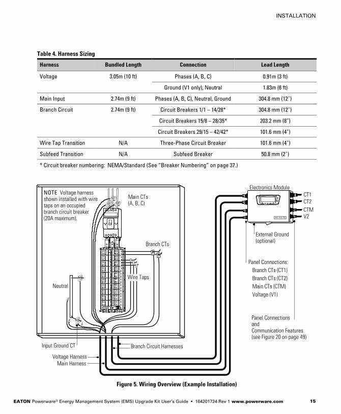
Table 4. Harness Sizing
Harness Bundled Length Connection Lead Length
Voltage 3.05m (10 ft) Phases (A, B, C) 0.91m (3 ft)
Ground (V1 only), Neutral 1.83m (6 ft)
Main Input 2.74m (9 ft) Phases (A, B, C), Neutral, Ground 304.8 mm (12")
Branch Circuit 2.74m (9 ft) Circuit Breakers 1/1 – 14/28* 304.8 mm (12")
Circuit Breakers 15/8 – 28/35* 203.2 mm (8")
Circuit Breakers 29/15 – 42/42* 101.6 mm (4")
Wire Tap Transition N/A Three−Phase Circuit Breaker 101.6 mm (4")
Subfeed Transition N/A Subfeed Breaker 50.8 mm (2")
* Circuit breaker numbering: NEMA/Standard (See �Breaker Numbering" on page 37.)
NOTE Voltage harnessshown installed with wiretaps on an occupiedbranch circuit breaker(20A maximum).
Voltage (V1)
Main CTs (CTM)
Branch CTs (CT2)
Branch CTs (CT1)
Panel Connections:
Panel ConnectionsandCommunication Features(see Figure 20 on page 49)
Electronics Module
Branch Circuit Harnesses
Voltage HarnessMain Harness
Main CTs(A, B, C)
Wire Taps
Branch CTs
Neutral
Input Ground CT
CT1CT2
CTMV2
External Ground(optional)
Figure 5. Wiring Overview (Example Installation)
INSTALLATION
EATON Powerware® Energy Management System (EMS) Upgrade Kit User’s Guide � 164201724 Rev 1 www.powerware.com16
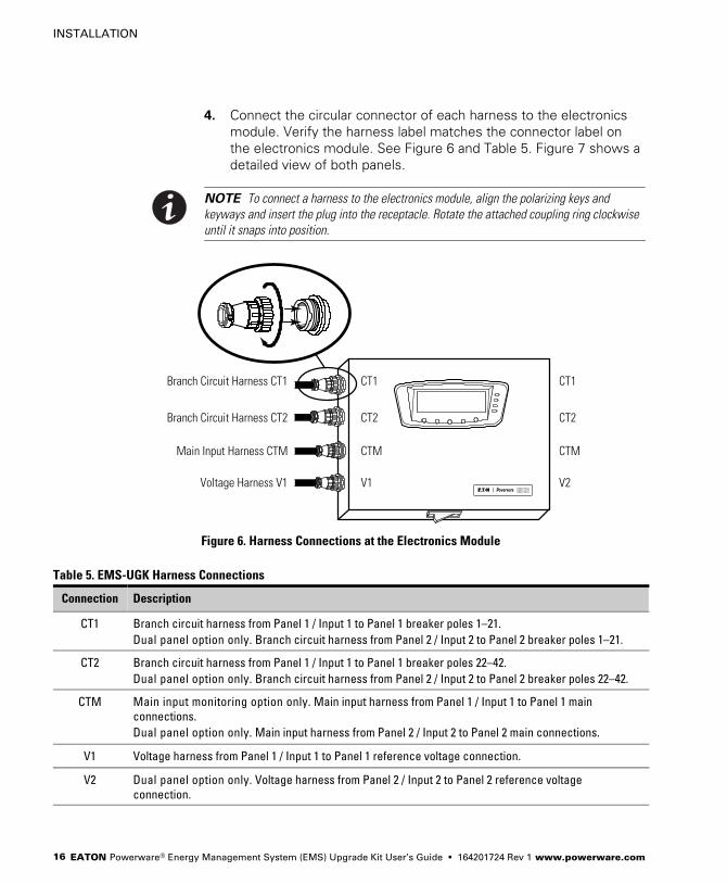
4. Connect the circular connector of each harness to the electronics
module. Verify the harness label matches the connector label on
the electronics module. See Figure 6 and Table 5. Figure 7 shows a
detailed view of both panels.
NOTE To connect a harness to the electronics module, align the polarizing keys and
keyways and insert the plug into the receptacle. Rotate the attached coupling ring clockwise
until it snaps into position.
CT1
CT2
CTM
V1
CT1
CT2
CTM
V2
Branch Circuit Harness CT1
Branch Circuit Harness CT2
Main Input Harness CTM
Voltage Harness V1
Figure 6. Harness Connections at the Electronics Module
Table 5. EMS−UGK Harness Connections
Connection Description
CT1 Branch circuit harness from Panel 1 / Input 1 to Panel 1 breaker poles 1–21.
Dual panel option only. Branch circuit harness from Panel 2 / Input 2 to Panel 2 breaker poles 1–21.
CT2 Branch circuit harness from Panel 1 / Input 1 to Panel 1 breaker poles 22–42.
Dual panel option only. Branch circuit harness from Panel 2 / Input 2 to Panel 2 breaker poles 22–42.
CTM Main input monitoring option only. Main input harness from Panel 1 / Input 1 to Panel 1 main
connections.
Dual panel option only. Main input harness from Panel 2 / Input 2 to Panel 2 main connections.
V1 Voltage harness from Panel 1 / Input 1 to Panel 1 reference voltage connection.
V2 Dual panel option only. Voltage harness from Panel 2 / Input 2 to Panel 2 reference voltage
connection.
INSTALLATION
EATON Powerware® Energy Management System (EMS) Upgrade Kit User’s Guide � 164201724 Rev 1 www.powerware.com 17
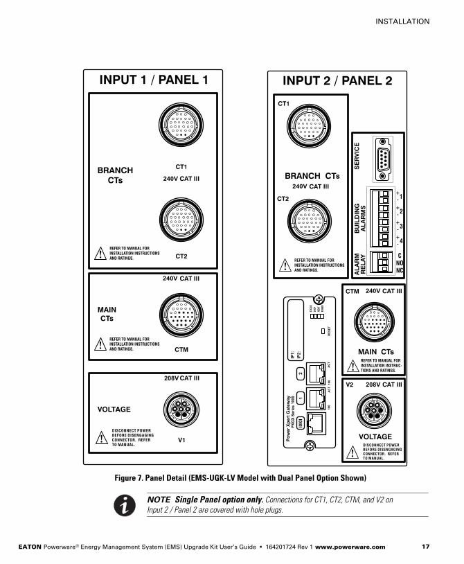
Figure 7. Panel Detail (EMS−UGK−LV Model with Dual Panel Option Shown)
NOTE Single Panel option only. Connections for CT1, CT2, CTM, and V2 on
Input 2 / Panel 2 are covered with hole plugs.
INSTALLATION
EATON Powerware® Energy Management System (EMS) Upgrade Kit User’s Guide � 164201724 Rev 1 www.powerware.com18
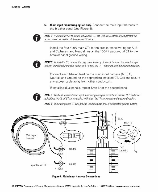
5. Main input monitoring option only. Connect the main input harness to
the breaker panel (see Figure 8):
NOTE If you prefer not to install the Neutral CT, the EMS−UGK software can perform an
approximate calculation of the Neutral CT values.
Install the four 400A main CTs to the breaker panel wiring for A, B,
and C phases, and Neutral. Install the 100A input ground CT to the
breaker panel ground wiring.
NOTE To install a CT, remove the cap, open the body of the CT to insert the wire through
the slit, and reinstall the cap. Install all CTs with the �H1" lettering facing the same direction.
Connect each labeled lead on the main input harness (A, B, C,
Neutral, and Ground) to the appropriate installed CT. Coil and secure
any excess cable away from other conductors.
If installing dual panels, repeat Step 5 for the second panel.
NOTE Verify all installed main input monitoring wiring is correct and follows NEC and local
guidelines. Verify all CTs are installed with their �H1" lettering facing the same direction.
NOTE The input ground CT will provide valid readings only in an isolated ground system.
C
C
B
A
Neutral
Ground
100A
400A
400A
Main InputHarness
�H1"Lettering
Input Ground CT
Main CT
Cap
Figure 8. Main Input Harness Connections
INSTALLATION
EATON Powerware® Energy Management System (EMS) Upgrade Kit User’s Guide � 164201724 Rev 1 www.powerware.com 19
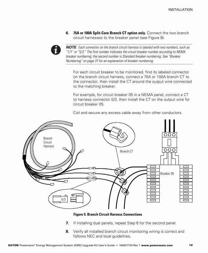
6. 75A or 100A Split−Core Branch CT option only. Connect the two branch
circuit harnesses to the breaker panel (see Figure 9):
NOTE Each connector on the branch circuit harness is labeled with two numbers, such as
�1/1" or �5/3." The first number indicates the circuit breaker number according to NEMA
breaker numbering; the second number is Standard breaker numbering. See �Breaker
Numbering" on page 37 for an explanation of breaker numbering.
For each circuit breaker to be monitored, find its labeled connector
on the branch circuit harness, connect a 75A or 100A branch CT to
the connector, then install the CT around the output wire connected
to the matching breaker.
For example, for circuit breaker 05 in a NEMA panel, connect a CT
to harness connector 5/3, then install the CT on the output wire for
circuit breaker 05.
Coil and secure any excess cable away from other conductors.
5/3
Breaker 05
BranchCircuitHarness
Branch CT
Figure 9. Branch Circuit Harness Connections
7. If installing dual panels, repeat Step 6 for the second panel.
8. Verify all installed branch circuit monitoring wiring is correct and
follows NEC and local guidelines.
INSTALLATION
EATON Powerware® Energy Management System (EMS) Upgrade Kit User’s Guide � 164201724 Rev 1 www.powerware.com20
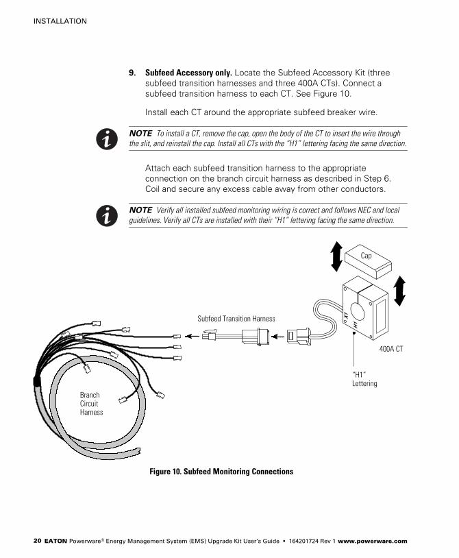
9. Subfeed Accessory only. Locate the Subfeed Accessory Kit (three
subfeed transition harnesses and three 400A CTs). Connect a
subfeed transition harness to each CT. See Figure 10.
Install each CT around the appropriate subfeed breaker wire.
NOTE To install a CT, remove the cap, open the body of the CT to insert the wire through
the slit, and reinstall the cap. Install all CTs with the �H1" lettering facing the same direction.
Attach each subfeed transition harness to the appropriate
connection on the branch circuit harness as described in Step 6.
Coil and secure any excess cable away from other conductors.
NOTE Verify all installed subfeed monitoring wiring is correct and follows NEC and local
guidelines. Verify all CTs are installed with their �H1" lettering facing the same direction.
Subfeed Transition Harness
400A CT
BranchCircuitHarness
�H1"Lettering
Cap
Figure 10. Subfeed Monitoring Connections

INSTALLATION
EATON Powerware® Energy Management System (EMS) Upgrade Kit User’s Guide � 164201724 Rev 1 www.powerware.com 21
C A U T I O N� Panel 1 voltage sensing includes a ground wire, but Panel 2 voltage sensing does not. If
installing dual panels, connect the voltage harness V1 for Panel 1 first. Whendisconnecting dual panels, disconnect the voltage harness V2 for Panel 2 first.
� Use the branch circuit breakers to disconnect hazardous voltage from the EMS−UGK. Turnoff the breaker before disconnecting the voltage measuring circuit cables, or hazardousvoltage may be present at the exposed end of the cable.
10. On the voltage harness V1 for Panel 1, locate the green and yellow
Ground wire. Attach the Ground ferrule to a ground point within the
panel. See Figure 5 on page 15.
11. Attach the Neutral wire to the Neutral bar in the panel. See Figure 5
on page 15.
C A U T I O NBefore connecting the voltage harness to a branch circuit breaker, shut down the branchcircuit breaker. Risk of electric shock.
12. Choose an option for connecting the phases for voltage sensing:
NOTE Maximum branch circuit breaker size where the voltage sensing is located is 20A.
� Use the supplied wire tap transition harnesses to connect the
voltage harness to an unoccupied three−phase branch circuit
breaker (continue to Step 13).
� Use the supplied wire taps to connect the voltage harness to an
occupied three−phase branch circuit breaker (proceed to Step 14
on page 23).
INSTALLATION
EATON Powerware® Energy Management System (EMS) Upgrade Kit User’s Guide � 164201724 Rev 1 www.powerware.com22
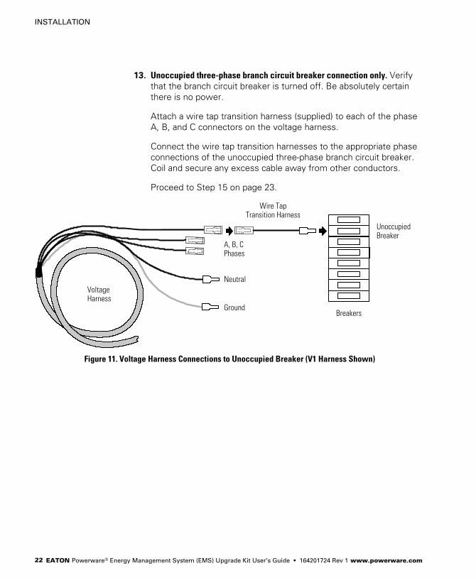
13. Unoccupied three−phase branch circuit breaker connection only. Verify
that the branch circuit breaker is turned off. Be absolutely certain
there is no power.
Attach a wire tap transition harness (supplied) to each of the phase
A, B, and C connectors on the voltage harness.
Connect the wire tap transition harnesses to the appropriate phase
connections of the unoccupied three−phase branch circuit breaker.
Coil and secure any excess cable away from other conductors.
Proceed to Step 15 on page 23.
Breakers
A, B, CPhases
Ground
NeutralVoltageHarness
UnoccupiedBreaker
Wire TapTransition Harness
Figure 11. Voltage Harness Connections to Unoccupied Breaker (V1 Harness Shown)

INSTALLATION
EATON Powerware® Energy Management System (EMS) Upgrade Kit User’s Guide � 164201724 Rev 1 www.powerware.com 23
NOTE Use wire taps ONLY on thermoplastic insulation (PVC).
14. Occupied three−phase branch circuit breaker connection only. Verify that
the branch circuit breaker is turned off. Be absolutely certain there
is no power.
Use pliers to carefully install the appropriate size wire taps
(supplied) to phase A, B, and C wiring on the occupied circuit
breaker. See Figure 12. For sizing, see Table 3 on page 14.
Verify the wire taps are completely closed around the wires.
Connect the phase A, B, and C connectors on the voltage harness
to the appropriate installed wire taps. Coil and secure any excess
cable away from other conductors.
Wire Tap
A, B, CPhases
Ground
NeutralVoltageHarness
Wiring to Occupied Breaker
Figure 12. Voltage Harness Connections to Occupied Breaker (V1 Harness Shown)
15. If installing dual panels, repeat Steps 11 through 14 for the voltage
harness V2 and Panel 2 for Neutral, A, B, and C phase connections.
Panel 2 does not have a Ground connection.
16. Verify all installed voltage monitoring wiring is correct and follows
NEC and local guidelines.
INSTALLATION
EATON Powerware® Energy Management System (EMS) Upgrade Kit User’s Guide � 164201724 Rev 1 www.powerware.com24
17. If installing communication functions, install the wiring for the Alarm
Relay and Building Alarms connections. For more information, see
�Communication" on page 49.
18. Start up the host equipment. Refer to the user’s guide for the host
equipment for startup instructions.
19. Activate the reset switch on the bottom of the electronics module:
hold the switch for 10 seconds or until the display (if installed) turns
off, then release the switch.
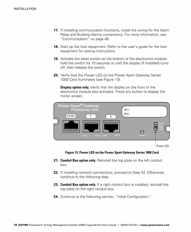
20. Verify that the Power LED on the Power Xpert Gateway Series
1000 Card illuminates (see Figure 13).
Display option only. Verify that the display on the front of the
electronics module also activates. Press any button to display the
mimic screen.
Power LED
Figure 13. Power LED on the Power Xpert Gateway Series 1000 Card
21. Conduit Box option only. Reinstall the top plate on the left conduit
box.
22. If installing network connections, proceed to Step 24. Otherwise,
continue to the following step.
23. Conduit Box option only. If a right conduit box is installed, reinstall the
top plate on the right conduit box.
24. Continue to the following section, �Initial Configuration."
INSTALLATION
EATON Powerware® Energy Management System (EMS) Upgrade Kit User’s Guide � 164201724 Rev 1 www.powerware.com 25
Initial Configuration
This section describes how to use the supplied software configuration
tool to perform initial configuration and calibration. You can use either
the tool or the optional display (if installed) to configure the panels and
breakers.
After initial configuration, interface with the EMS−UGK using a Web page
interface, the Advanced Metering monitoring system, or (if the optional
display is installed) directly through the display.
Installing the Software Configuration Tool
NOTE For best results, install the software configuration tool on a computer running the
Microsoft® Windows® XP or Windows 2000 operating system.
To install the software configuration tool:
1. Connect a computer to the service port on the electronics module
using the supplied DB−9 to RS−232 serial cable.
2. Set the computer’s COM port settings to COM1, 19200 baud.
3. Verify that the computer’s settings for the date and time are
correct. The configuration tool uses the computer’s settings to
automatically set the date and time for the EMS−UGK. You can
disable this feature later if needed.
4. Insert the EMS Configuration Tool CD into the computer’s CD drive.
The installation program begins automatically within 10 seconds.
If the installation program does not begin automatically, run the
CD_Menu.exe program on the CD.
5. Follow the installation program instructions to install the tool.
6. Continue to the following section, �Initial System Configuration."
INSTALLATION
EATON Powerware® Energy Management System (EMS) Upgrade Kit User’s Guide � 164201724 Rev 1 www.powerware.com26
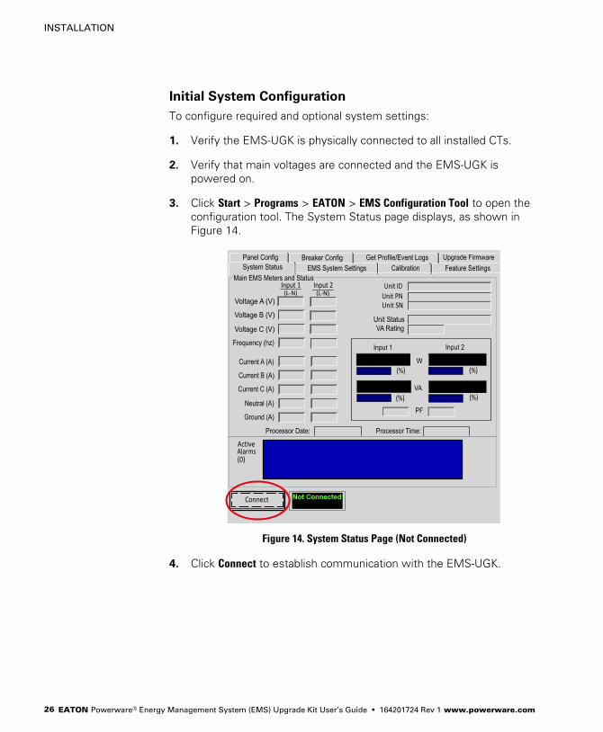
Initial System Configuration
To configure required and optional system settings:
1. Verify the EMS−UGK is physically connected to all installed CTs.
2. Verify that main voltages are connected and the EMS−UGK is
powered on.
3. Click Start > Programs > EATON > EMS Configuration Tool to open the
configuration tool. The System Status page displays, as shown in
Figure 14.
Figure 14. System Status Page (Not Connected)
4. Click Connect to establish communication with the EMS−UGK.
INSTALLATION
EATON Powerware® Energy Management System (EMS) Upgrade Kit User’s Guide � 164201724 Rev 1 www.powerware.com 27
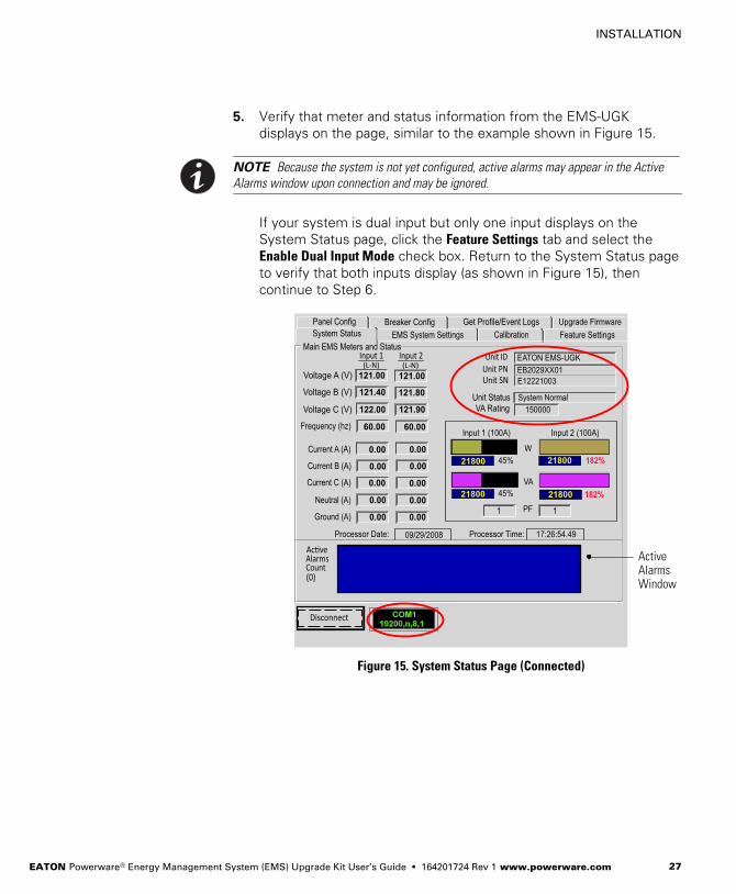
5. Verify that meter and status information from the EMS−UGK
displays on the page, similar to the example shown in Figure 15.
NOTE Because the system is not yet configured, active alarms may appear in the Active
Alarms window upon connection and may be ignored.
If your system is dual input but only one input displays on the
System Status page, click the Feature Settings tab and select the
Enable Dual Input Mode check box. Return to the System Status page
to verify that both inputs display (as shown in Figure 15), then
continue to Step 6.
ActiveAlarmsWindow
Figure 15. System Status Page (Connected)
INSTALLATION
EATON Powerware® Energy Management System (EMS) Upgrade Kit User’s Guide � 164201724 Rev 1 www.powerware.com28
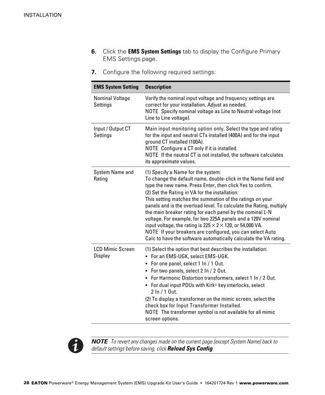
6. Click the EMS System Settings tab to display the Configure Primary
EMS Settings page.
7. Configure the following required settings:
EMS System Setting Description
Nominal Voltage
Settings
Verify the nominal input voltage and frequency settings are
correct for your installation. Adjust as needed.
NOTE Specify nominal voltage as Line to Neutral voltage (not
Line to Line voltage).
Input / Output CT
Settings
Main input monitoring option only. Select the type and rating
for the input and neutral CTs installed (400A) and for the input
ground CT installed (100A).
NOTE Configure a CT only if it is installed.
NOTE If the neutral CT is not installed, the software calculates
its approximate values.
System Name and
Rating
(1) Specify a Name for the system:
To change the default name, double−click in the Name field and
type the new name. Press Enter, then click Yes to confirm.
(2) Set the Rating in VA for the installation:
This setting matches the summation of the ratings on your
panels and is the overload level. To calculate the Rating, multiply
the main breaker rating for each panel by the nominal L−N
voltage. For example, for two 225A panels and a 120V nominal
input voltage, the rating is 225�2�120, or 54,000 VA.
NOTE If your breakers are configured, you can select Auto
Calc to have the software automatically calculate the VA rating.
LCD Mimic Screen
Display
(1) Select the option that best describes the installation:
� For an EMS−UGK, select EMS−UGK.
� For one panel, select 1 In / 1 Out.
� For two panels, select 2 In / 2 Out.
� For Harmonic Distortion transformers, select 1 In / 2 Out.
� For dual input PDUs with Kirk® key interlocks, select
2 In / 1 Out.
(2) To display a transformer on the mimic screen, select the
check box for Input Transformer Installed.
NOTE The transformer symbol is not available for all mimic
screen options.
NOTE To revert any changes made on the current page (except System Name) back to
default settings before saving, click Reload Sys Config.

INSTALLATION
EATON Powerware® Energy Management System (EMS) Upgrade Kit User’s Guide � 164201724 Rev 1 www.powerware.com 29
8. Optional. To prevent the software configuration tool from
synchronizing with the PC date and time, select Don’t auto update.
9. Click Save Sys Config to save the settings to the EMS−UGK.
Depending on communication speed, updates take effect within
15–20 seconds.
10. Optional. Voltage and current calibration is performed at the factory.
The EMS−UGK does not require calibration. If you choose to
recalibrate, the original calibrated values will be lost.
To recalibrate the settings, click the Calibration tab to display the
EMS System Calibration page.
NOTE For optimal results, verify that the circuits are loaded to nominal load levels prior to
starting calibration. Have qualified service personnel (such as a licensed electrician) obtain
the physical measurements using a multimeter and RMS current probe. For calibration,
measure the L−N voltage (not L−L voltage).
Enter the voltage and current measurements from the installed
panel(s) on the EMS System Calibration page. Blank fields will not
be calibrated.
NOTE To revert any changes made on the current page back to default settings before
saving, click Reload Cal Data.
Click Save Cal Data to update the voltage calibration data and save
the settings to the EMS−UGK. Depending on communication speed,
updates take effect within 15–20 seconds.
INSTALLATION
EATON Powerware® Energy Management System (EMS) Upgrade Kit User’s Guide � 164201724 Rev 1 www.powerware.com30
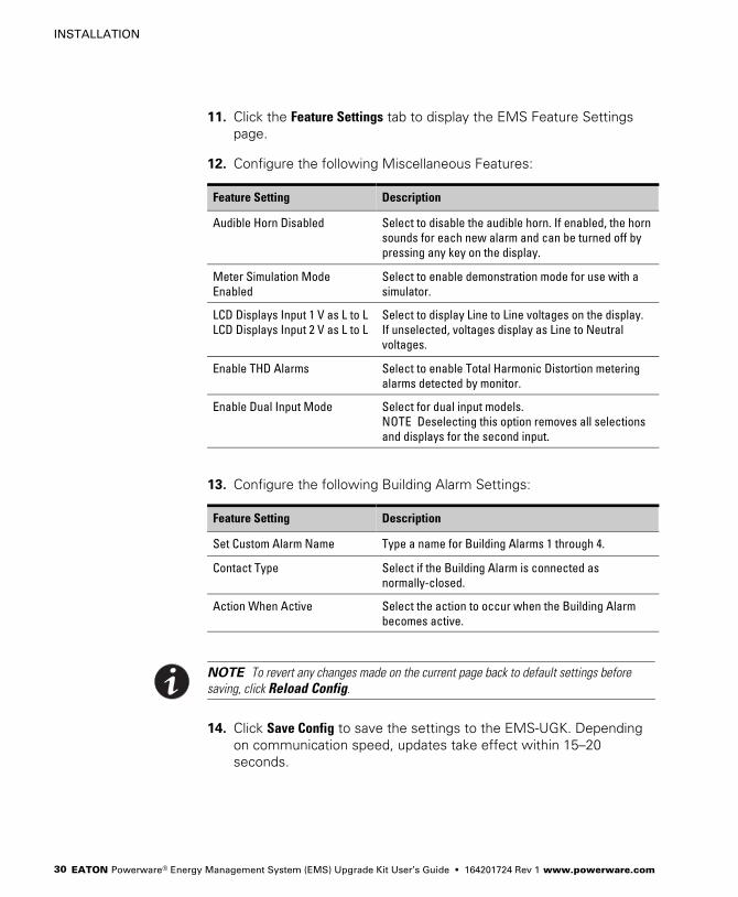
11. Click the Feature Settings tab to display the EMS Feature Settings
page.
12. Configure the following Miscellaneous Features:
Feature Setting Description
Audible Horn Disabled Select to disable the audible horn. If enabled, the horn
sounds for each new alarm and can be turned off by
pressing any key on the display.
Meter Simulation Mode
Enabled
Select to enable demonstration mode for use with a
simulator.
LCD Displays Input 1 V as L to L
LCD Displays Input 2 V as L to L
Select to display Line to Line voltages on the display.
If unselected, voltages display as Line to Neutral
voltages.
Enable THD Alarms Select to enable Total Harmonic Distortion metering
alarms detected by monitor.
Enable Dual Input Mode Select for dual input models.
NOTE Deselecting this option removes all selections
and displays for the second input.
13. Configure the following Building Alarm Settings:
Feature Setting Description
Set Custom Alarm Name Type a name for Building Alarms 1 through 4.
Contact Type Select if the Building Alarm is connected as
normally−closed.
Action When Active Select the action to occur when the Building Alarm
becomes active.
NOTE To revert any changes made on the current page back to default settings before
saving, click Reload Config.
14. Click Save Config to save the settings to the EMS−UGK. Depending
on communication speed, updates take effect within 15–20
seconds.

INSTALLATION
EATON Powerware® Energy Management System (EMS) Upgrade Kit User’s Guide � 164201724 Rev 1 www.powerware.com 31
15. To configure panels and breakers using the software configuration
tool, continue to the following section, �Initial Panel and Breaker
Configuration (Using the Software Configuration Tool)."
To configure panels and breakers using the optional display,
continue to Step 16.
16. Click Disconnect to disconnect from the EMS−UGK. Verify that �Not
Connected" displays at the bottom of the page.
17. Close the software configuration tool and remove the configuration
cable.
18. Activate the reset switch on the bottom of the electronics module:
hold the switch for 10 seconds or until the display (if installed) turns
off, then release the switch.
19. Continue to �Initial Panel and Breaker Configuration (Using the
Display)" on page 34.
Initial Panel and Breaker Configuration (Using the
Software Configuration Tool)
To configure the panels and breakers:
1. Click the Panel Config tab to display the EMS Panel Settings page.
2. Verify that the Number of BCM Panels Installed is correct for your
installation.
If you change the value, click Save Panel Config to save the setting to
the EMS−UGK. Depending on communication speed, updates take
effect within 15–20 seconds.
3. Select the panel number to configure (Panel Selected).

INSTALLATION
EATON Powerware® Energy Management System (EMS) Upgrade Kit User’s Guide � 164201724 Rev 1 www.powerware.com32
4. Configure the following settings for the selected panel:
Panel Setting Description
Panel Rating Specify the panel breaker rating (in amps).
NOTE Setting the panel breaker rating to 0 silences all
main panel breaker alarms and zeroes the panel percent
current levels.
Panel Warn (%) Specify the warning threshold level (in percent load).
Panel Alarm (%) Specify the alarm threshold level (in percent load).
Num Brkr Positions Specify the number of breakers in the panel.
Panel Name Specify a panel name (up to 19 characters).
Panel Serial Number Specify the panel’s serial number (up to 19 characters).
Panel Layout Specify the panel numbering style.
NOTE Changing panel layout erases all branch circuit
breaker configurations.
NOTE To revert any changes made on the current page back to default settings before
saving, click Reload Panel Config.
5. Click Save Panel Config to save the settings to the EMS−UGK.
Depending on communication speed, updates take effect within
15–20 seconds.
6. Repeat Steps 3 through 5 to configure the remaining panels.
7. Click the Breaker Config tab to display the Breaker Settings page.
The tool automatically updates the default breaker schedule with
the latest information from the EMS−UGK. Depending on
communication speed, updates take effect within 15–20 seconds.
8. Select the Panel Number of the panel containing the breakers to
configure. The tool automatically updates the selected breaker
schedule with the latest information from the EMS−UGK.
Depending on communication speed, updates take effect within
15–20 seconds.

INSTALLATION
EATON Powerware® Energy Management System (EMS) Upgrade Kit User’s Guide � 164201724 Rev 1 www.powerware.com 33
9. The selected breaker is highlighted in bold in the schedule. The
breaker’s configuration details display in the right half of the page.
Click the breaker to configure. The breaker number highlights and
its details display at right.
10. Configure the following settings for the selected breaker:
Breaker Setting Description
Num Phases Specify the number of phases (1–3).
Breaker Rating Specify the branch breaker rating (in amps).
Warning Level Specify the warning threshold level (in percent load).
Alarm Level Specify the alarm threshold level (in percent load).
CT Ratio Specify the current transformer ratio (75A).
NOTE The selected ratio converts to the value 71.9.
NOTE To revert any changes made on the current page back to default settings before
saving, click Reload Breaker Config.
11. Repeat Steps 9 and 10 to configure the remaining breakers in the
panel.
12. Click Save Breaker Config to save the settings to the EMS−UGK.
13. Repeat Steps 8 through 12 to configure the breakers in the
remaining panels.
14. Click Disconnect to disconnect from the EMS−UGK. Verify that �Not
Connected" displays at the bottom of the page.
15. Close the software configuration tool and remove the configuration
cable.
16. Activate the reset switch on the bottom of the electronics module:
hold the switch for 10 seconds or until the display (if installed) turns
off, then release the switch.
17. Continue to �Advanced Metering Installation" on page 36.

INSTALLATION
EATON Powerware® Energy Management System (EMS) Upgrade Kit User’s Guide � 164201724 Rev 1 www.powerware.com34
Initial Panel and Breaker Configuration (Using the Display)
NOTE Use this section only if the optional display is installed.
Configure the panel and breaker data. You can use the following
abbreviated instructions or follow the more detailed steps in �Control
Panel Configuration" on page 43.
1. From the setup screen, enter the Level 1 access password (default
password is L1).
2. Select Meters then Panel, highlight the panel to configure, then
select Config.
3. Set the Reset value to Yes and select OK to clear any breaker
configuration settings for the panel.
4. Configure the following settings to match the physical panel:
Phases (always three−phase)
Breakers (the number of breakers in the panel)
Rating (the rating in Amps of the main panel breaker)
Panel Layout (panel numbering style)
5. Highlight the panel number and select Schedule.
6. Highlight the breaker to configure and select Config.
7. Configure the following settings to match the physical breaker:
Phases (number of phases for the breaker)
Rating (breaker rating in Amps)
Warning (alarm warning level in %)
Overload (alarm overload level in %)
CT (the CT ratio – specify 71.9)
8. Configure each installed breaker in the panel.
9. If a second panel is installed, repeat the panel and breaker
configuration for the second panel.
10. Activate the reset switch on the bottom of the electronics module:
hold the switch for 10 seconds or until the display (if installed) turns
off, then release the switch.

INSTALLATION
EATON Powerware® Energy Management System (EMS) Upgrade Kit User’s Guide � 164201724 Rev 1 www.powerware.com 35
11. From the setup screen, clear the History Log and Load Profile. For
detailed instructions, see �Setup Options� on page 42.
12. Continue to the following section, �Advanced Metering
Installation."
INSTALLATION
EATON Powerware® Energy Management System (EMS) Upgrade Kit User’s Guide � 164201724 Rev 1 www.powerware.com36
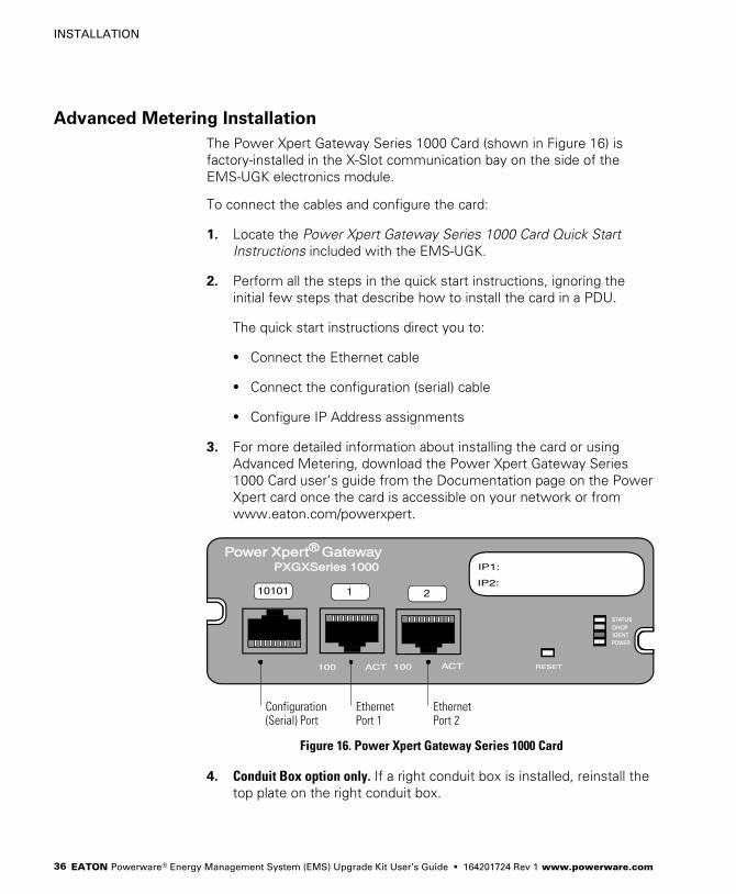
Advanced Metering Installation
The Power Xpert Gateway Series 1000 Card (shown in Figure 16) is
factory−installed in the X−Slot communication bay on the side of the
EMS−UGK electronics module.
To connect the cables and configure the card:
1. Locate the Power Xpert Gateway Series 1000 Card Quick Start
Instructions included with the EMS−UGK.
2. Perform all the steps in the quick start instructions, ignoring the
initial few steps that describe how to install the card in a PDU.
The quick start instructions direct you to:
� Connect the Ethernet cable
� Connect the configuration (serial) cable
� Configure IP Address assignments
3. For more detailed information about installing the card or using
Advanced Metering, download the Power Xpert Gateway Series
1000 Card user’s guide from the Documentation page on the Power
Xpert card once the card is accessible on your network or from
www.eaton.com/powerxpert.
EthernetPort 2
EthernetPort 1
Configuration(Serial) Port
Figure 16. Power Xpert Gateway Series 1000 Card
4. Conduit Box option only. If a right conduit box is installed, reinstall the
top plate on the right conduit box.

EATON Powerware® Energy Management System (EMS) Upgrade Kit User’s Guide � 164201724 Rev 1 www.powerware.com 37
Chapter 3 Operation
This chapter describes how to use the Energy Management System
(EMS) Upgrade Kit (EMS−UGK) interface.
Reset Function
The EMS−UGK is intended for continuous duty operation. Cycle power
for the EMS−UGK using the reset switch at the base of the electronics
module: hold the switch for 10 seconds or until the display (if installed)
turns off, then release the switch. The switch is intended for use as a
programming reset function.
NOTE The reset switch controls power to the transformer inside the electronics module.
The reset switch does not remove three−phase sensing voltage from the Universal Control
Board (UCB).
Breaker Numbering
NEMA numbering is left to right in a two−column panel. Odd−numbered
breakers are on the left and even−numbered breakers are on the right.
Standard numbering is top to bottom down the left side of the panel,
then top to bottom down the right side of the panel.
See Figure 17.
050301 02
0406 03
0201
242322
NEMAPanel
StandardPanel
04 25
Figure 17. Breaker Numbering
OPERATION
EATON Powerware® Energy Management System (EMS) Upgrade Kit User’s Guide � 164201724 Rev 1 www.powerware.com38
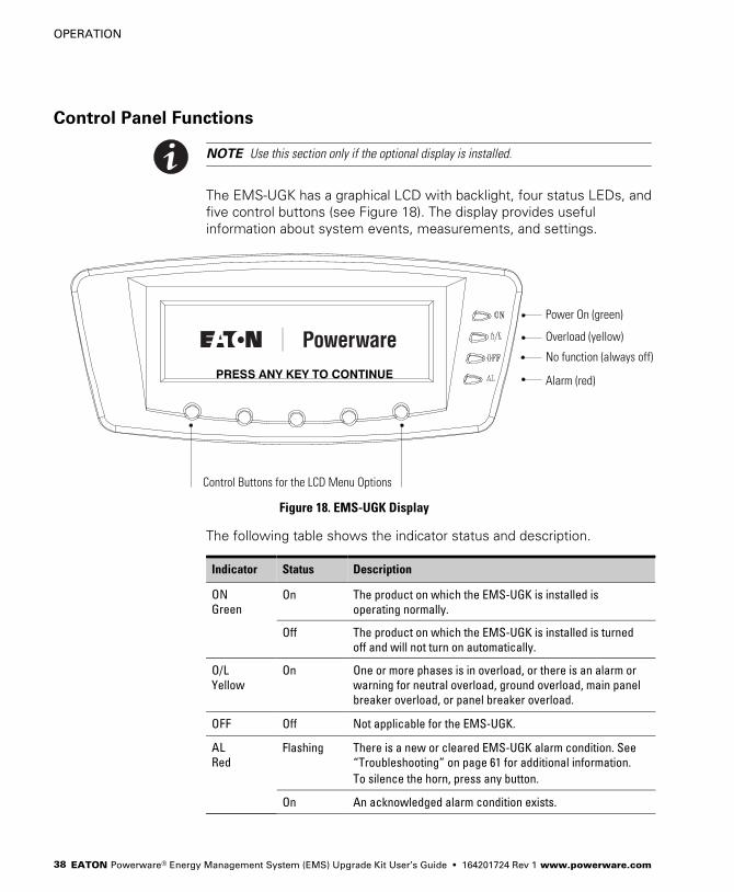
Control Panel Functions
NOTE Use this section only if the optional display is installed.
The EMS−UGK has a graphical LCD with backlight, four status LEDs, and
five control buttons (see Figure 18). The display provides useful
information about system events, measurements, and settings.
PRESS ANY KEY TO CONTINUE
Power On (green)
Overload (yellow)
No function (always off)
Alarm (red)
Control Buttons for the LCD Menu Options
Figure 18. EMS−UGK Display
The following table shows the indicator status and description.
Indicator Status Description
ON
GreenOn The product on which the EMS−UGK is installed is
operating normally.
Off The product on which the EMS−UGK is installed is turned
off and will not turn on automatically.
O/L
Yellow
On One or more phases is in overload, or there is an alarm or
warning for neutral overload, ground overload, main panel
breaker overload, or panel breaker overload.
OFF Off Not applicable for the EMS−UGK.
AL
RedFlashing There is a new or cleared EMS−UGK alarm condition. See
�Troubleshooting" on page 61 for additional information.
To silence the horn, press any button.
On An acknowledged alarm condition exists.

OPERATION
EATON Powerware® Energy Management System (EMS) Upgrade Kit User’s Guide � 164201724 Rev 1 www.powerware.com 39
Display Functions
The LCD displays the Eaton Powerware logo. Press any button to
activate the mimic screen and menu options (see Figure 19). The mimic
screen shows a real−time graphical representation of the operating
status of the system. At the top of the screen, an information line cycles
through displays of information such as the date and time and any active
alarms or events.
To select a menu option, press the button below the option name.
When available:
� Use the and buttons to scroll through a listing of information.
� Use the and buttons to select another item on the screen to
view or change.
� Use the + or — button to increase or decrease a selected value.
� Press the button to return to the previous menu.
NOTE After making configuration changes, you can save your changes immediately by
pressing the Reset button on the Power Xpert Gateway Card installed in the X−Slot
communication bay. The card resets automatically after five minutes.
The backlit LCD automatically dims after a long period of inactivity. Press
any button to restore the screen.
EATON EMS−UGK
PROFILE
ME-
TER
EVENT
S
SET-
UP
000.0000.0000.0
000.0000.0000.0
Input 2 / Panel 2Input 1 / Panel 1 Unit Name
EMS
PROFILEMETEREVENTS SETUP
Figure 19. EMS−UGK Mimic Screen and Main Menu

OPERATION
EATON Powerware® Energy Management System (EMS) Upgrade Kit User’s Guide � 164201724 Rev 1 www.powerware.com40
Menu Map
The following tables show the basic menu structure.
Table 6. Menu Map for Display Functions
Main Menu Submenu Display Information or Menu Function
Events Active Events Displays list of active system events. As events clear, they are removed from the list.
History Displays historical log of system events. The log stores the most recent 127 events
and alarms.
Meter* Input 2 Displays Input 2 / Panel 2 performance meters for the system or critical load:
RMS / % / THD / Crest / KWH
Select PANEL to configure or view panel meters (see Table 7 for detail).**
Select PANEL then SCHEDULE to configure or view breaker meters (see Table 8 for
detail).**
Input 1 Displays Input 1 / Panel 1 performance meters for the system or critical load:
RMS / % / THD / Crest / KWH
Select PANEL to configure or view panel meters (see Table 7 for detail).**
Select PANEL then SCHEDULE to configure or view breaker meters (see Table 8 for
detail).**
Profile* Displays load profile for the most recent 24 months. Profile includes highest and
lowest input and output currents, frequencies, power levels, power factors,
AC undervoltage, THD, and exact time each reading occurred. Current month’s profile
reflects real−time values.
Setup* Displays setup options. See Table 9 on page 42 for detail.
* Information displayed depends on product configuration.
** Configuration options are password−protected.
OPERATION
EATON Powerware® Energy Management System (EMS) Upgrade Kit User’s Guide � 164201724 Rev 1 www.powerware.com 41
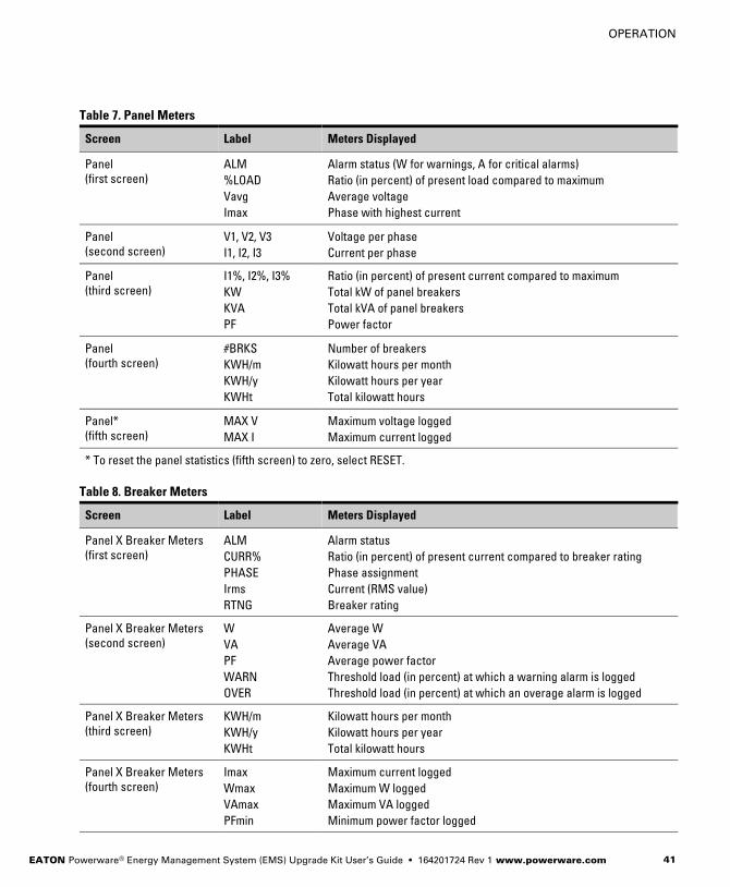
Table 7. Panel Meters
Screen Label Meters Displayed
Panel
(first screen)
ALM
%LOAD
Vavg
Imax
Alarm status (W for warnings, A for critical alarms)
Ratio (in percent) of present load compared to maximum
Average voltage
Phase with highest current
Panel
(second screen)
V1, V2, V3
I1, I2, I3
Voltage per phase
Current per phase
Panel
(third screen)
I1%, I2%, I3%
KW
KVA
PF
Ratio (in percent) of present current compared to maximum
Total kW of panel breakers
Total kVA of panel breakers
Power factor
Panel
(fourth screen)
#BRKS
KWH/m
KWH/y
KWHt
Number of breakers
Kilowatt hours per month
Kilowatt hours per year
Total kilowatt hours
Panel*
(fifth screen)
MAX V
MAX I
Maximum voltage logged
Maximum current logged
* To reset the panel statistics (fifth screen) to zero, select RESET.
Table 8. Breaker Meters
Screen Label Meters Displayed
Panel X Breaker Meters
(first screen)
ALM
CURR%
PHASE
Irms
RTNG
Alarm status
Ratio (in percent) of present current compared to breaker rating
Phase assignment
Current (RMS value)
Breaker rating
Panel X Breaker Meters
(second screen)
W
VA
PF
WARN
OVER
Average W
Average VA
Average power factor
Threshold load (in percent) at which a warning alarm is logged
Threshold load (in percent) at which an overage alarm is logged
Panel X Breaker Meters
(third screen)
KWH/m
KWH/y
KWHt
Kilowatt hours per month
Kilowatt hours per year
Total kilowatt hours
Panel X Breaker Meters
(fourth screen)
Imax
Wmax
VAmax
PFmin
Maximum current logged
Maximum W logged
Maximum VA logged
Minimum power factor logged

OPERATION
EATON Powerware® Energy Management System (EMS) Upgrade Kit User’s Guide � 164201724 Rev 1 www.powerware.com42
Setup Options
Access to setup options is restricted to three System Setup Levels: 0, 1,
or 2. The higher the level, the more setup options are available. Options
on System Setup Level 0 do not require password access.
Table 9. Setup Options
MinimumLevel*
Description Available Settings Default Setting
0 Enter Password Use the arrow keys to enter the password for the level you
want to access, then select DONE to display the options for
the setup level
Level 1: L1
Level 2: Contact your
service representative
0 Versions Read only Current firmware
versions installed
0 Contrast Adjust Adjust screen contrast with left/right arrow buttons 10%
1 Log Out Exit the Level 1 or Level 2 setup options and display the
Level 0 setup options
None
1 Change Access
Level Password
Change the password for the current setup level
Use the arrow keys to enter the new password (A–Z, 0–9, –,
blank,), then select DONE to save the new password.
None
1 Set Date and Time Set Month, Date, Year (mm/dd/yyyy)
Set Hour, Minute (Time is a 24−hour clock.)
00/00/0000
00:00
1 Clear History Clear the History Log None
1 Clear Load Profile Clear the Load Profile None
1 Building Alarm
Setup
(see page 53)
For Building Alarm 1 through Building Alarm 4:
Name String [up to 19 characters (A–Z, 0–9, –, blank)]
Settings: Contact Normally Open or Closed
Building Alarm Type (REPO, EPO, TVSS/SPD,
Custom)
Notice Level (Log and Alarm options)
Enabled/Disabled
BUILDING ALARM [X]
Open
1 and 2: Custom;
3: REPO; 4: EPO
Log Only
Enabled
1 THD Alarm Level Set the voltage and current Total Harmonic Distortion for
Input 1 and Input 2, and enable or disable this feature:
THD settings
Enabled/Disabled
5.0
Disabled
2 Unit Type Read only: Model / CTO / Serial Factory−set identifiers
2 Unit Name Up to 19 characters (A–Z, 0–9, –, blank) EATON EMS−UGK
2 Reset All Lower
Level Passwords
Reset the Level 1 password to the default setting None
* Minimum System Setup Level required to access the setup option.

OPERATION
EATON Powerware® Energy Management System (EMS) Upgrade Kit User’s Guide � 164201724 Rev 1 www.powerware.com 43
Control Panel Configuration
NOTE Use this section only if the optional display is installed.
To set up branch circuit monitoring on your product, configure the panels
and branch circuit breakers. Configuration requires System Setup
Level 1 password access.
Accessing Configuration
To access the configuration options at System Setup Level 1:
1. In the Setup menu, select ENTER PASSWORD.
2. Use the arrow keys to enter the password (default password is L1
for Level 1).
3. Select DONE. The screen displays the setup options.
To change the default password while logged into System Setup Level 1
access:
1. In the Setup menu, select CHANGE ACCESS LEVEL PASSWORD.
2. Use the arrow keys to enter the new password (A–Z, 0–9, –, blank).
3. Select DONE.
Configuring Panels Containing Branch Circuit Breakers
To configure panels containing branch circuit breakers:
1. If not already obtained, access the System Setup Level 1 password
level. See the previous section, �Accessing Configuration."
2. From the main menu, select METER then PANEL.
3. On the PANEL screen, select the panel number (PNL) to configure,
and then select CONFIG.

OPERATION
EATON Powerware® Energy Management System (EMS) Upgrade Kit User’s Guide � 164201724 Rev 1 www.powerware.com44
4. On the PANEL CONFIG screen, set the panel’s meter settings:
Default Range Meter Setting Description
3 3 PHASES Number of phases
42 0–42
(even numbers)
BREAKERS Number of branch circuit
breakers in the panel
100 0–1200 RATING Panel breaker rating (in amps)
(see Note 1)
STANDARD STANDARD
COLUMN
PNL LAYOUT Panel layout
(see Note 2)
NOTE 1 Setting the panel breaker rating to 0 silences all main panel breaker
alarms and zeroes the panel percent current levels.
NOTE 2 Changing panel layout erases all branch circuit breaker configurations.
To reset all values on the screen to defaults, set the RESET value to
YES.
5. Select OK.
6. Repeat Steps 3 to 5 for each panel containing branch circuit
breakers to configure.
7. When all panel configuration is complete, select the button
repeatedly to reach the main menu.
8. If all configuration is complete, save your changes by pressing the
Reset button on the Power Xpert Gateway Card in the X−Slot
communication bay. (The card automatically resets after five
minutes.) Otherwise, continue to �Configuring Branch Circuit
Breakers" on page 46.
Configuring Panels Containing Subfeed Breakers
To configure panels containing subfeed breakers (up to 12 per panel):
1. If not already obtained, access the System Setup Level 1 password
level. See �Accessing Configuration" on page 43.
2. From the main menu, select METER then PANEL.
3. On the PANEL screen, select the panel number (PNL) to configure,
and then select CONFIG.

OPERATION
EATON Powerware® Energy Management System (EMS) Upgrade Kit User’s Guide � 164201724 Rev 1 www.powerware.com 45
4. On the PANEL CONFIG screen, set the panel’s meter settings:
Default Range Meter Setting Description
3 3 PHASES Number of phases
42 0–42
(even numbers)
BREAKERS* Number of subfeed breakers in
the panel, times 3
100 0–1200 RATING Subfeed breaker rating (in amps)
(see Note 1)
STANDARD STANDARD
COLUMN
PNL LAYOUT Panel layout
(see Note 2)
* For example, if the panel has 6 subfeed breakers, set the BREAKERS value to 18.
NOTE 1 Setting the panel breaker rating to 0 silences all main panel breaker
alarms and zeroes the panel percent current levels.
NOTE 2 Changing panel layout erases all branch circuit breaker configurations.
To reset all values on the screen to defaults, set the RESET value to
YES.
5. Select OK, the panel number (PNL), then SCHEDULE.
On the PANEL SCHEDULE screen, each subfeed breaker displays
as a group of three phases.
6. Select the button to return to the PANEL screen.
7. Repeat Steps 3 to 6 for each panel containing subfeed breakers to
configure.
8. When all panel configuration is complete, select the button
repeatedly to reach the main menu.
9. If all configuration is complete, save your changes by pressing the
Reset button on the Power Xpert Gateway Card in the X−Slot
communication bay. (The card automatically resets after five
minutes.) Otherwise, continue to the following section,
�Configuring Branch Circuit Breakers."
OPERATION
EATON Powerware® Energy Management System (EMS) Upgrade Kit User’s Guide � 164201724 Rev 1 www.powerware.com46
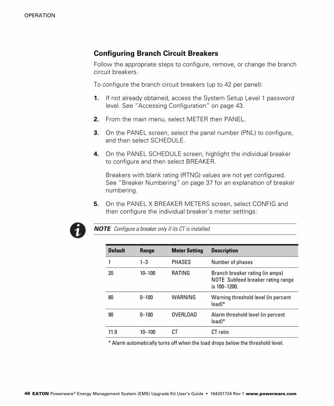
Configuring Branch Circuit Breakers
Follow the appropriate steps to configure, remove, or change the branch
circuit breakers.
To configure the branch circuit breakers (up to 42 per panel):
1. If not already obtained, access the System Setup Level 1 password
level. See �Accessing Configuration" on page 43.
2. From the main menu, select METER then PANEL.
3. On the PANEL screen, select the panel number (PNL) to configure,
and then select SCHEDULE.
4. On the PANEL SCHEDULE screen, highlight the individual breaker
to configure and then select BREAKER.
Breakers with blank rating (RTNG) values are not yet configured.
See �Breaker Numbering" on page 37 for an explanation of breaker
numbering.
5. On the PANEL X BREAKER METERS screen, select CONFIG and
then configure the individual breaker’s meter settings:
NOTE Configure a breaker only if its CT is installed.
Default Range Meter Setting Description
1 1–3 PHASES Number of phases
20 10–100 RATING Branch breaker rating (in amps)
NOTE Subfeed breaker rating range
is 100–1200.
80 0–100 WARNING Warning threshold level (in percent
load)*
90 0–100 OVERLOAD Alarm threshold level (in percent
load)*
71.9 10–100 CT CT ratio
* Alarm automatically turns off when the load drops below the threshold level.

OPERATION
EATON Powerware® Energy Management System (EMS) Upgrade Kit User’s Guide � 164201724 Rev 1 www.powerware.com 47
6. When the individual circuit configuration is complete, select OK to
return to the PANEL SCHEDULE screen to configure the next
breaker.
7. When all branch circuit configuration is complete, select the
button repeatedly to reach the main menu.
8. If all configuration is complete, save your changes by pressing the
Reset button on the Power Xpert Gateway Card in the X−Slot
communication bay. (The card automatically resets after five
minutes.)
To remove a breaker from the panel:
1. If not already obtained, access the System Setup Level 1 password
level. See �Accessing Configuration" on page 43.
2. From the main menu, select METER then PANEL.
3. Highlight the panel number (PNL), and then select SCHEDULE.
4. Highlight the breaker to remove, and then select BREAKER and
DELETE.
5. Select the button repeatedly to reach the main menu.
6. If all configuration is complete, save your changes by pressing the
Reset button on the Power Xpert Gateway Card in the X−Slot
communication bay. (The card automatically resets after five
minutes.)
To change a breaker’s settings:
1. If not already obtained, access the System Setup Level 1 password
level. See �Accessing Configuration" on page 43.
2. Follow the steps to remove a breaker from the panel.
3. Follow the steps to configure a breaker.

OPERATION
EATON Powerware® Energy Management System (EMS) Upgrade Kit User’s Guide � 164201724 Rev 1 www.powerware.com48
Viewing Panel Meters
NOTE Use this section only if the optional display is installed.
To view the meters for the panels:
1. From the main menu, select METER then PANEL.
2. Use the arrow keys to scroll through the panel meters (listed in
Table 7 on page 41).
To reset a panel’s meter statistics, scroll to the last panel screen,
highlight the panel number, and select RESET.
3. When viewing is complete, select the button repeatedly to reach
the main menu.
Viewing Breaker Meters
NOTE Use this section only if the optional display is installed.
To view the meters for the breakers:
1. From the main menu, select METER then PANEL.
2. On the PANEL screen, select the panel number (PNL) to view, and
then select SCHEDULE.
3. The PANEL SCHEDULE screen shows each breaker’s alarm status
and rating. Use the up and down arrow keys to scroll through the
list of breakers.
4. To view the meters for an individual breaker, highlight the breaker
number, and then select BREAKER.
The PANEL X BREAKER METERS screens show meters for the
selected breaker (listed in Table 8 on page 41). Use the left and
right arrow keys to scroll through the meters.
5. When viewing is complete, select the button repeatedly to reach
the main menu.
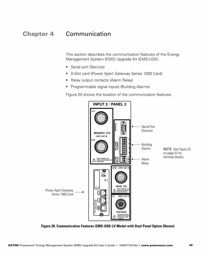
EATON Powerware® Energy Management System (EMS) Upgrade Kit User’s Guide � 164201724 Rev 1 www.powerware.com 49
Chapter 4 Communication
This section describes the communication features of the Energy
Management System (EMS) Upgrade Kit (EMS−UGK):
� Serial port (Service)
� X−Slot card (Power Xpert Gateway Series 1000 Card)
� Relay output contacts (Alarm Relay)
� Programmable signal inputs (Building Alarms)
Figure 20 shows the location of the communication features.
Serial Port(Service)
NOTE See Figure 22on page 52 forterminal details.
BuildingAlarms
AlarmRelay
Power Xpert GatewaySeries 1000 Card
Figure 20. Communication Features (EMS−UGK−LV Model with Dual Panel Option Shown)
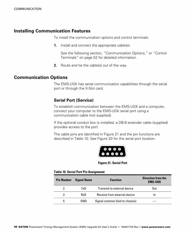
COMMUNICATION
EATON Powerware® Energy Management System (EMS) Upgrade Kit User’s Guide � 164201724 Rev 1 www.powerware.com50
Installing Communication Features
To install the communication options and control terminals:
1. Install and connect the appropriate cable(s).
See the following section, �Communication Options," or �Control
Terminals" on page 52 for detailed information.
2. Route and tie the cable(s) out of the way.
Communication Options
The EMS−UGK has serial communication capabilities through the serial
port or through the X−Slot card.
Serial Port (Service)
To establish communication between the EMS−UGK and a computer,
connect your computer to the EMS−UGK serial port using a
communication cable (not supplied).
If the optional conduit box is installed, a DB−9 extender cable (supplied)
provides access to the port.
The cable pins are identified in Figure 21 and the pin functions are
described in Table 10. See Figure 20 for the serial port location.
3
87 9
1
6
2 4 5
Figure 21. Serial Port
Table 10. Serial Port Pin Assignment
Pin Number Signal Name Function Direction from theEMS−UGK
2 TxD Transmit to external device Out
3 RxD Receive from external device In
5 GND Signal common (tied to chassis) �

COMMUNICATION
EATON Powerware® Energy Management System (EMS) Upgrade Kit User’s Guide � 164201724 Rev 1 www.powerware.com 51
Use the computer’s HyperTerminal® (or equivalent) application to access
Terminal mode. Table 11 lists available keystroke combinations for using
Terminal mode through the EMS−UGK communication port.
Table 11. Terminal Mode
Key Combination* Display Comment
[ESC] [A] Active Events Displays a list of active events.
[ESC] [H] History Log Prints the History Log with a firmware version header, beginning with the
oldest entry. Alarms that occur while the log is printing are included in
chronological order.
System events are continually logged through the serial port to the device
connected to the port.
[ESC] [P] Profile Log Prints the Profile Log, beginning with the oldest entries.
[ESC] [V] All screens
(video mode)
Navigate the screens just as on the EMS−UGK’s display, substituting the
keyboard keys 1, 2, 3, 4, and 5 for the five pushbuttons on the EMS−UGK
display. The indicators display as text to the right of the main screen.
* Hold down the [ESC] key and press the letter key.
X−Slot Card
The Power Xpert Gateway Series 1000 Card installed in the X−Slot
communication bay provides remote monitoring through a Web browser
interface, e−mail, and a network managment system using SNMP;
connects to a twisted−pair Ethernet (10/100BaseT) network. Modbus®
TCP support provides direct integration of a monitored panel’s
parameters to a Building Management System (BMS). It has a built−in
switching hub that allows one additional network device to be
connected to the network without the requirement of an additional
network drop.
NOTE LAN drops for use with the X−Slot card must be provided by the customer.
See Figure 20 on page 49 for the location of the X−Slot communication
bay.
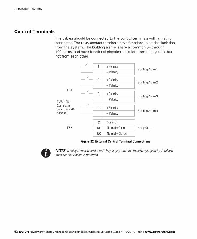
COMMUNICATION
EATON Powerware® Energy Management System (EMS) Upgrade Kit User’s Guide � 164201724 Rev 1 www.powerware.com52
Control Terminals
The cables should be connected to the control terminals with a mating
connector. The relay contact terminals have functional electrical isolation
from the system. The building alarms share a common (–) through
100 ohms, and have functional electrical isolation from the system, but
not from each other.
+ Polarity
– Polarity
1
+ Polarity
– Polarity
2
Building Alarm 1
Building Alarm 2
Normally Closed
Normally Open
NC
NO
CommonC
Relay Output
EMS−UGKConnectors (see Figure 20 onpage 49)
+ Polarity
– Polarity
4Building Alarm 4
+ Polarity
– Polarity
3Building Alarm 3
TB1
TB2
Figure 22. External Control Terminal Connections
NOTE If using a semiconductor switch type, pay attention to the proper polarity. A relay or
other contact closure is preferred.

COMMUNICATION
EATON Powerware® Energy Management System (EMS) Upgrade Kit User’s Guide � 164201724 Rev 1 www.powerware.com 53
Relay Output Contacts (Alarm Relay)
The EMS−UGK incorporates a programmable relay output with potential
free contacts for remote alarm indications.
The SPDT (single pole double throw) relay provides both NO and NC
contacts. These contacts can be connected to equipment at the facility
(such as a light or an alarm bell) to signal when an alarm is active on the
EMS−UGK. This feature is useful if the EMS−UGK is located in a remote
area where the EMS−UGK horn may not be heard immediately.
W A R N I N GThe relay output contacts must not be connected to any utility connected circuits. Reinforcedinsulation to the utility is required. The relay output contacts have a maximum rating of 8Aat 32 Vdc or less, derate to 1A at 60 Vdc. Do not operate above 42.4 Vpk or 60 Vdc.
Programmable Signal Inputs (Building Alarms)
The EMS−UGK incorporates four programmable signal inputs, each with
a signal and a signal return. When the signal is shorted, the input is read
as active. The pins must be shorted with maximum resistance of
10 ohm to activate the specific input. Seventeen milliamps are required
to drive the signal active.
NOTE See Figure 22 on page 52 for the polarity and verify these connections if polarity
control is required.
This feature lets you connect the EMS−UGK to your building alarms,
such as smoke detectors or overtemperature alarms. For each building
alarm, you can set:
� The building alarm name
� The contact type (NO or NC)
� The building alarm type
NOTE A building alarm programmed for REPO will trigger the REPO alarm and the alarm
associated with the building alarm number.
� The notice level
To configure the building alarms, see �Setup Options" on page 42.

COMMUNICATION
EATON Powerware® Energy Management System (EMS) Upgrade Kit User’s Guide � 164201724 Rev 1 www.powerware.com54
EATON Powerware® Energy Management System (EMS) Upgrade Kit User’s Guide � 164201724 Rev 1 www.powerware.com 55
Chapter 5 Maintenance
Keep the area around the hardware and wiring clean and dust-free. Wipe
with a dry cloth as needed. The Energy Management System (EMS)
Upgrade Kit (EMS−UGK) does not require an annual calibration.
Recycling the Used Equipment
Contact your local recycling or hazardous waste center for information
on proper disposal of the used equipment.
C A U T I O NDo not discard waste electrical or electronic equipment (WEEE) in the trash. For properdisposal, contact your local recycling/reuse or hazardous waste center.
Updating the Firmware
To keep the firmware updated with the latest improvements and
benefits, visit www.powerware.com often for updates. You can download
the latest firmware version and the instructions for installing it.
Replacing the Power Xpert Gateway Series 1000 Card
The card can be replaced easily without turning the EMS−UGK off or
disconnecting the load. Follow the instructions included with the card. If
the optional conduit box is installed:
NOTE See Figure 4 on page 12 for the location of conduit box components.
1. Remove the front plate on the right conduit box. Retain the plate
and screws for later reinstallation.
2. Remove the card cover plate at the bottom right of the right conduit
box. Retain the plate and screws for later reinstallation.
3. Follow the instructions included with the card to remove the old
card, replace with the new card, and verify operation.
4. Reinstall the card cover plate and front plate.
MAINTENANCE
EATON Powerware® Energy Management System (EMS) Upgrade Kit User’s Guide � 164201724 Rev 1 www.powerware.com56
Rewiring and Reconfiguring the Installation
D A N G E RThis EMS−UGK contains LETHAL VOLTAGES. All repairs and service should be performedby AUTHORIZED SERVICE PERSONNEL ONLY. There are NO USER SERVICEABLEPARTS inside the EMS−UGK.
W A R N I N G� Only qualified service personnel (such as a licensed electrician) shall perform the
electrical installation. Risk of electrical shock.
� Always follow all personal protective equipment (PPE) and other safety rules whenworking around electricity.
To rewire and reconfigure the EMS−UGK:
C A U T I O NBefore rewiring the EMS−UGK, disconnect the load and shut down the host equipment. Referto the user’s guide for the host equipment for shutdown instructions.
1. Depending on the rewiring involved, follow the appropriate
installation steps 1 through 20 (starting on page 13) to update the
harness and CT connections. Observe all warnings and cautionsassociated with the installation steps.
2. For each updated connection, reconfigure the appropriate settings
in the EMS−UGK using the supplied software configuration tool, a
web page interface, the Advanced Metering monitoring system, or
(if the optional display is installed) directly through the display. See
�Initial Configuration" on page 25.
3. Activate the reset switch on the bottom of the electronics module:
hold the switch for 10 seconds or until the display (if installed) turns
off, then release the switch.
4. Verify the rewired and reconfigured installation operates as
intended.
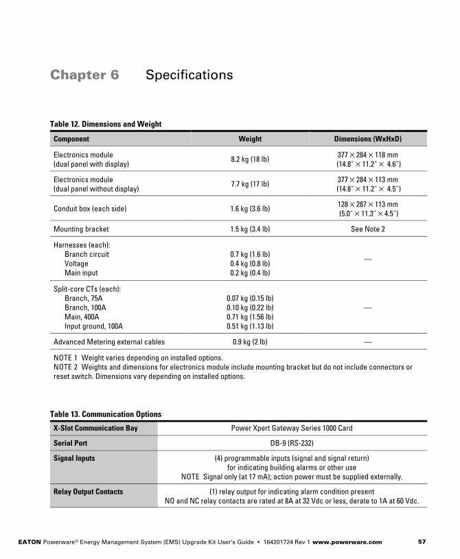
EATON Powerware® Energy Management System (EMS) Upgrade Kit User’s Guide � 164201724 Rev 1 www.powerware.com 57
Chapter 6 Specifications
Table 12. Dimensions and Weight
Component Weight Dimensions (WxHxD)
Electronics module
(dual panel with display)8.2 kg (18 lb)
377�284�118 mm
(14.8"�11.2"� 4.6")
Electronics module
(dual panel without display)7.7 kg (17 lb)
377�284�113 mm
(14.8"�11.2"� 4.5")
Conduit box (each side) 1.6 kg (3.6 lb)128�287�113 mm
(5.0"�11.3"�4.5")
Mounting bracket 1.5 kg (3.4 lb) See Note 2
Harnesses (each):
Branch circuit
Voltage
Main input
0.7 kg (1.6 lb)
0.4 kg (0.8 lb)
0.2 kg (0.4 lb)
�
Split−core CTs (each):
Branch, 75A
Branch, 100A
Main, 400A
Input ground, 100A
0.07 kg (0.15 lb)
0.10 kg (0.22 lb)
0.71 kg (1.56 lb)
0.51 kg (1.13 lb)
�
Advanced Metering external cables 0.9 kg (2 lb) �
NOTE 1 Weight varies depending on installed options.
NOTE 2 Weights and dimensions for electronics module include mounting bracket but do not include connectors or
reset switch. Dimensions vary depending on installed options.
Table 13. Communication Options
X−Slot Communication Bay Power Xpert Gateway Series 1000 Card
Serial Port DB−9 (RS−232)
Signal Inputs (4) programmable inputs (signal and signal return)
for indicating building alarms or other use
NOTE Signal only (at 17 mA); action power must be supplied externally.
Relay Output Contacts (1) relay output for indicating alarm condition present
NO and NC relay contacts are rated at 8A at 32 Vdc or less, derate to 1A at 60 Vdc.
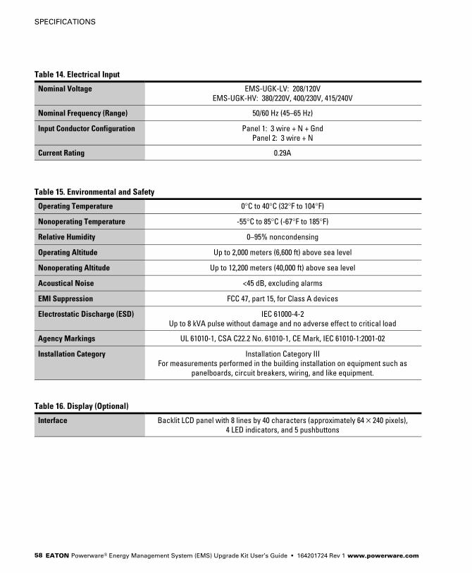
SPECIFICATIONS
EATON Powerware® Energy Management System (EMS) Upgrade Kit User’s Guide � 164201724 Rev 1 www.powerware.com58
Table 14. Electrical Input
Nominal Voltage EMS−UGK−LV: 208/120V
EMS−UGK−HV: 380/220V, 400/230V, 415/240V
Nominal Frequency (Range) 50/60 Hz (45–65 Hz)
Input Conductor Configuration Panel 1: 3 wire + N + Gnd
Panel 2: 3 wire + N
Current Rating 0.29A
Table 15. Environmental and Safety
Operating Temperature 0°C to 40°C (32°F to 104°F)
Nonoperating Temperature −55°C to 85°C (−67°F to 185°F)
Relative Humidity 0–95% noncondensing
Operating Altitude Up to 2,000 meters (6,600 ft) above sea level
Nonoperating Altitude Up to 12,200 meters (40,000 ft) above sea level
Acoustical Noise <45 dB, excluding alarms
EMI Suppression FCC 47, part 15, for Class A devices
Electrostatic Discharge (ESD) IEC 61000−4−2
Up to 8 kVA pulse without damage and no adverse effect to critical load
Agency Markings UL 61010−1, CSA C22.2 No. 61010−1, CE Mark, IEC 61010−1:2001−02
Installation Category Installation Category III
For measurements performed in the building installation on equipment such as
panelboards, circuit breakers, wiring, and like equipment.
Table 16. Display (Optional)
Interface Backlit LCD panel with 8 lines by 40 characters (approximately 64�240 pixels),
4 LED indicators, and 5 pushbuttons
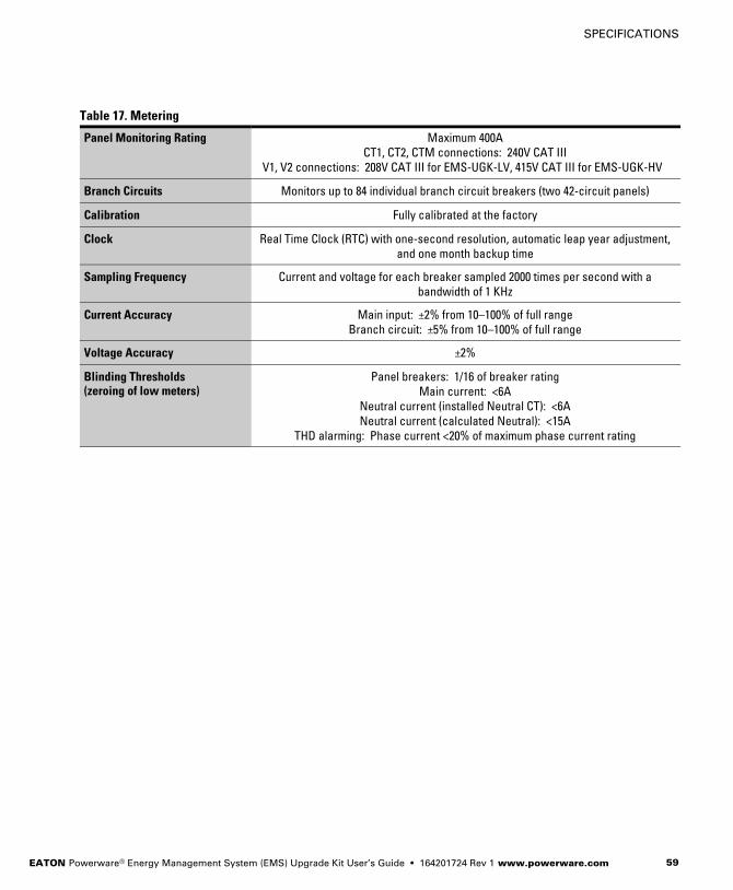
SPECIFICATIONS
EATON Powerware® Energy Management System (EMS) Upgrade Kit User’s Guide � 164201724 Rev 1 www.powerware.com 59
Table 17. Metering
Panel Monitoring Rating Maximum 400A
CT1, CT2, CTM connections: 240V CAT III
V1, V2 connections: 208V CAT III for EMS−UGK−LV, 415V CAT III for EMS−UGK−HV
Branch Circuits Monitors up to 84 individual branch circuit breakers (two 42−circuit panels)
Calibration Fully calibrated at the factory
Clock Real Time Clock (RTC) with one−second resolution, automatic leap year adjustment,
and one month backup time
Sampling Frequency Current and voltage for each breaker sampled 2000 times per second with a
bandwidth of 1 KHz
Current Accuracy Main input: ±2% from 10–100% of full range
Branch circuit: ±5% from 10–100% of full range
Voltage Accuracy ±2%
Blinding Thresholds(zeroing of low meters)
Panel breakers: 1/16 of breaker rating
Main current: <6A
Neutral current (installed Neutral CT): <6A
Neutral current (calculated Neutral): <15A
THD alarming: Phase current <20% of maximum phase current rating

SPECIFICATIONS
EATON Powerware® Energy Management System (EMS) Upgrade Kit User’s Guide � 164201724 Rev 1 www.powerware.com60
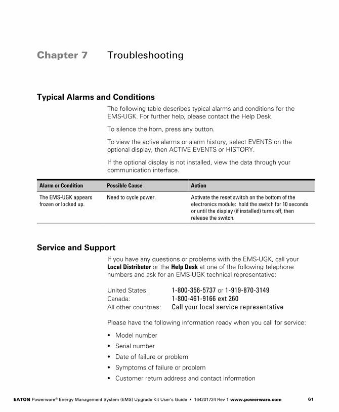
EATON Powerware® Energy Management System (EMS) Upgrade Kit User’s Guide � 164201724 Rev 1 www.powerware.com 61
Chapter 7 Troubleshooting
Typical Alarms and Conditions
The following table describes typical alarms and conditions for the
EMS−UGK. For further help, please contact the Help Desk.
To silence the horn, press any button.
To view the active alarms or alarm history, select EVENTS on the
optional display, then ACTIVE EVENTS or HISTORY.
If the optional display is not installed, view the data through your
communication interface.
Alarm or Condition Possible Cause Action
The EMS−UGK appears
frozen or locked up.
Need to cycle power. Activate the reset switch on the bottom of the
electronics module: hold the switch for 10 seconds
or until the display (if installed) turns off, then
release the switch.
Service and Support
If you have any questions or problems with the EMS−UGK, call your
Local Distributor or the Help Desk at one of the following telephone
numbers and ask for an EMS−UGK technical representative:
United States: 1−800−356−5737 or 1−919−870−3149
Canada: 1−800−461−9166 ext 260
All other countries: Call your local service representative
Please have the following information ready when you call for service:
� Model number
� Serial number
� Date of failure or problem
� Symptoms of failure or problem
� Customer return address and contact information

TROUBLESHOOTING
EATON Powerware® Energy Management System (EMS) Upgrade Kit User’s Guide � 164201724 Rev 1 www.powerware.com62

EATON Powerware® Energy Management System (EMS) Upgrade Kit User’s Guide � 164201724 Rev 1 www.powerware.com 63
Chapter 8 Warranty
Limited Factory Warranty
Powerware Energy Management System (EMS) Upgrade Kit
WARRANTOR: The warrantor for the limited warranties set forth herein is Eaton Electrical Inc., a Delaware
Corporation (�Eaton").
LIMITED WARRANTY: This limited warranty (�Warranty") applies only to the original end−user (�End−User") of the
Powerware EMS Upgrade Kit (�Product") and cannot be transferred. This Warranty applies even in the event that
the Product is initially sold by Eaton for resale to an End−User.
LIMITED WARRANTY PERIOD: The period covered by this Warranty for Product installed [and currently located] in
the fifty (50) United States and the District of Columbia is twelve (12) months from the date of Product shipment for
parts replacement. The period covered by this Warranty for Product installed [and currently located] outside of the
fifty (50) United States and the District of Columbia is twelve (12) months from the date of Product shipment for
parts replacement.
WHAT THIS LIMITED WARRANTY COVERS: The warrantor warrants that the Powerware EMS Upgrade Kit and
Eaton−provided accessories (individually and collectively, "Warranted Items") are free from defects in material and
workmanship. If, in the opinion of Eaton, a Warranted Item is defective and the defect is within the terms of this
Warranty, Eaton’s sole obligation will be to repair or replace such defective item (including by providing service,
parts, and labor, as applicable), at the option of Eaton. Any parts that are replaced may be new or reconditioned. All
parts replaced by Eaton shall become the property of Eaton. The End−User shall return the defective part or parts to
a location specified by Eaton.
WHAT THIS LIMITED WARRANTY DOES NOT COVER: This Warranty does not cover any defects or damages
caused by: (a) failure to properly store the Product before installation; (b) shipping and delivery of the Product if
shipping is FOB Factory; (c) neglect, accident, fire, flood, lightning, vandalism, acts of God, End−User’s neglect,
abuse, misuse, misapplication, incorrect installation; (d) repair or alteration not authorized in writing by Eaton
personnel or performed by an authorized Eaton Customer Service Engineer or Agent; or (e) improper testing,
operation, maintenance, adjustment, or any modification of any kind not authorized in writing by Eaton personnel or
performed by an authorized Eaton Customer Service Engineer or Agent.
This Warranty is not valid: (a) if the Product is moved to a new location by someone other than an authorized Eaton
Customer Service Engineer (in the USA) or Agent (outside of the USA); or (b) if the Product’s serial numbers have
been removed or are illegible. Any Warranted Items repaired or replaced pursuant to this Warranty will be warranted
for the remaining portion of the original Warranty subject to all the terms thereof. Labor warranty is not provided.
Any equipment, parts, or materials included in the Product and not manufactured by Eaton are warranted solelyby the manufacturer of such equipment, parts, or materials and are not included as part of this Warranty.
THIS WARRANTY IS THE END−USER’S SOLE REMEDY AND IS EXPRESSLY IN LIEU OF, AND THERE ARE NO OTHEREXPRESSED OR IMPLIED GUARANTEES OR WARRANTIES (INCLUDING ANY IMPLIED WARRANTY OFMERCHANTABILITY OR FITNESS FOR ANY PURPOSE, WHICH ARE EXPRESSLY DISCLAIMED).
LIMITATION OF LIABILITY: In no event shall Eaton be liable for any indirect, incidental, special, or consequential
damages of any kind or type whatsoever, or based on any claim or cause of action, however denominated. Eaton
shall not be responsible for failure to provide service or parts due to causes beyond Eaton’s reasonable control. In
no case will Eaton’s liability under this Warranty exceed the replacement value of the Warranted Items.

WARRANTY
EATON Powerware® Energy Management System (EMS) Upgrade Kit User’s Guide � 164201724 Rev 1 www.powerware.com64
END−USER’S OBLIGATIONS: In order to receive the benefits of this Warranty, the End−User must use the Product
in a normal way, follow the Product’s user’s guide, and protect against further damage to the Product if there is a
covered defect.
OTHER LIMITATIONS: Eaton’s obligations under this Warranty are expressly conditioned upon receipt by Eaton of
all payments due to it (including interest charges, if any). During such time as Eaton has not received payment of
any amount due to it for the Product, in accordance with the contract terms under which the Product is sold, Eaton
shall have no obligation under this Warranty. Also during such time, the period of this Warranty shall continue to run
and the expiration of this Warranty shall not be extended upon payment of any overdue or unpaid amounts.
COSTS NOT RELATED TO WARRANTY: The End−User shall be invoiced for, and shall pay for, all services not
expressly provided for by the terms of this Warranty. Any costs for replacement equipment, installation, materials,
freight charges, travel expenses, or labor of Eaton representatives outside the terms of this Warranty will be borne
by the End−User.
OBTAINING WARRANTY SERVICE: In the USA, call the Eaton Customer Reliability Center 7x24 at 800−843−9433.
Outside of the USA, call your local Eaton sales or service representative, or call the Eaton Customer Reliability
Center in the USA at 919−870−3028. For comments or questions about this Limited Factory Warranty, write to the
Customer Quality Representative, 3301 Spring Forest Road, Raleigh, North Carolina 27616 USA.


*1642017241*164201724 1