
Powertronic Generation III
33
Powertronic Generation III
Transcript of Powertronic Generation III

1
Powertronic Generation III
2
Contents
Datalink system ............................................................................................................... 3Control units ................................................................................................................... 4
TECU ......................................................................................................................... 4Powertronic, general ........................................................................................................ 5
The main components ................................................................................................ 5Power transmission .......................................................................................................... 6
Torque converter ........................................................................................................ 6Control system ................................................................................................................ 7
Valve positioning in the control system ....................................................................... 7Solenoid and relay valves ............................................................................................. 8
Lock-up clutch ................................................................................................................. 9PWM valve S14 governs Lock-up ............................................................................... 9
Power take-off ................................................................................................................ 10Function ................................................................................................................... 10
Retarder......................................................................................................................... 11Emergency power steering pump ................................................................................... 13Hydraulic circuit ............................................................................................................. 14
Main pressure P1 ...................................................................................................... 14Torque converter pressure PC................................................................................... 15Lubrication ............................................................................................................... 15Check-measurement of the gearbox’s oil pressure .................................................... 15
1st gear (6-speed variant) .............................................................................................. 162nd gear (1st gear in 5-speed variant) ............................................................................ 173rd gear (2nd gear in 5-speed variant) ........................................................................... 184th gear (3rd gear in 5-speed variant) ............................................................................ 195th gear (4th gear in 5-speed variant) ............................................................................ 206th gear (5th gear in 5-speed variant) ............................................................................ 21Reverse gear R1 ............................................................................................................. 22Reverse gear R2 (reverse gear R on 5-speed variant) ..................................................... 23Changing gear without power loss (Powershift) ............................................................ 24Gear selector and display ............................................................................................... 25
Automatic mode (A) ................................................................................................ 26Manual mode (M) ..................................................................................................... 26Display ...................................................................................................................... 26
Component location ...................................................................................................... 27Power transmission ........................................................................................................ 28Clutches and brakes in the transmission ........................................................................ 28Sensors and solenoid valves in the transmission system ................................................. 28Hydraulic diagram.......................................................................................................... 29Components .................................................................................................................. 30Pressure sockets/pressure ............................................................................................. 31Solenoid valves .............................................................................................................. 32

3
Datalink system
The principle behind the new in-vehicle electronic systems developed by Volvo Trucks is that all communica-tion between the control units goes via two datalinks.
The vehicle’s main components are equipped with their own control units, which are connected to thedatalinks for communication with each other.
General
Communication between the various control units and feedback from the control units to the diagnosticsocket and instruments take place via datalinks SAE J1939 and SAE J1708. Note that the illustration showsthe principle for how the control units, diagnostic socket and instrument are connected to the links.
The instruments, vehicle control unit, engine control unit and diagnostic socket are always included in thesystem. Other control units vary with the individual market, vehicle variant and vehicle specification.
SAE J1939 (control link)
The system’s control signals are sent via this link, which is extremely fast.
SAE J1708 (information link)
The information link is connected to the control units, diagnostic socket and instrument. It is used to sendinformation and diagnostic signals. The information link is also used to keep the system’s status continuouslyupdated and accessible for reading.

4
Control units
The task of the gearbox control unit (TECU) is to govern gear-changes by ensuring that the correct gear isalways engaged. The control unit is therefore coupled to the control link since the gearbox status affectsother vehicle functions. The important information which the driver can see in the display is obtained fromthe instrument (Cluster) which receives its signals from the control unit via the information link. Theinstrument display is used by the Powertronic system to show the gear selector status, the selected gear,possible ratio changes, button status and the system’s status via fault codes.
The vehicle control unit provides the Powertronic system with information about the status of the parkingbrake and vehicle speed and required retarder torque.
The engine control unit is used primarily for changing engine revs and engine torque.
The brake control unit is used mainly to disengage the retarder function when the wheels lock.
The gearbox/retarder control units are used to regulate the gearbox and retarder.
TECU
The gearbox control unit (TECU) collects a variety of information from the gearbox’s various sensors. Thesensors provide information about the input and output revs in the torque converter, oil pressure, oil leveland oil temperature. When the gearbox control unit has to open a solenoid valve, it applies a regulatingvoltage of about 24 volts (U bat) across the valve, which then opens.
The following sensors are attached to the gearbox:
• Output shaft rev sensor (758), for control unit TECU
• Oil pressure sensor, gearbox (761)
• Oil temperature sensor, gearbox (762)
• Oil level sensor, gearbox (763)
• Oil temperature sensor, retarder (767)
• Sensor, tachograph/speedometer (7052)
• Engine rev sensor (7070)
• Turbine speed sensor (7076)
• Gear selector control unit GECU (9080)
• Gearbox control unit TECU (9057)

5
Powertronic, general
The gearbox is divided into five sections (A-E). In the front section (A) there is a torque converter with alock-up function. The oil pump and power take-off are found in section (B). Behind the pump in section (C)is the retarder, while section (D) contains the clutches, designated K1 and K2, as well as brake B1. Section(E) contains 4 or 5 planetary gears and 3 or 4 brakes B2 to B5, depending on whether this is a 5-speed or 6-speed variant.
The main components
The gearbox consists of the following main components:
• Torque converter (section A). Transfers the power from the engine to the gearbox. The torque converter isequipped with a direct coupling known as Lock-Up, which mechanically links the engine’s flywheel to thegearbox.
• Oil pump (section B). The oil pump supplies the regulating system with oil pressure. In this section it isalso a gear wheel for the Power take-off.
• Retarder (section C). Hydraulically brakes the gearbox’s input shaft. It thus gives the vehicle extra brakingpower. This type of retarder is known as a primary retarder.
• Forward/reverse clutches (section D). Join together the turbine shaft with the mainshaft or tubular shaft orboth at the same time, depending on which gear is selected.
• Brakes (sections D-E). Lock parts of the planetary gears to the gearbox housing.
• Planetary gears (section E). Provide various ratios in various combinations with each other.
• Control system. With valves that regulate oil flow and oil pressure to the gearbox’s clutches and brakes,and pressure for the torque converter and lubricating oil.
• Control system. With the gearbox control unit (TECU) and gear selector control unit (GECU) and othercontrols and sensors.

6
Power transmission
The following parts transfer power through the gearbox:
A. Pump wheelB. Turbine wheelC. StatorD. Turbine shaftE. Forward clutch (K1)
Torque converter
The torque converter consists of a pump wheel (A), a turbine wheel (B) that is linked with the turbine shaft(D) and a stator (C). The space between the pump wheel and turbine wheel is filled with oil. The pumpwheel is attached to the engine’s flywheel. When the flywheel begins to rotate, the impellers on the pumpwheel force the oil to flow in the direction of the arrow. Oil from the pump wheel flows to the turbine wheeland forces this to rotate in the same direction as the pump wheel.
The stator, which is located between the pump wheel and turbine wheel, is equipped with a free wheel sothat it can rotate freely in one direction. The impellers on the stator direct the oil flow from the turbinewheel back to the pump wheel’s impellers.
The torque converter provides smooth transmission of drive power from the engine to the gearbox. Thispower is transferred to the turbine shaft (C) hydraulically or via the lock-up clutch (M). Part of the engine’sdrive power is transmitted directly via the pump wheel (A) and the inter mediater gear (J) to the powertake-off and to the gearbox’s oil pumps (L) via the drive sleeve (K), which is fitted to the torque converter.
Low gear
At the rear of the gearbox in the 6-speed variant is a low-gear unit. The 5-speed variant has one planetarygear and one brake less than the 6-speed variant. The rear cover and output shaft differ from those in the 6-speed variant.
F. Reverse clutch (K2)G. MainshaftH. Tubular axleI. Output shaftJ. Inter mediater gear
B A
C D
EG
I
F H
6
L
J
K
M
D
C
AB
5
K. Drive SleeveL. Oil pumpM. Lock-up clutch

7
Control system
Valve positioning in the control system
Most of the valves are gathered together in the control system in the oil sump. (The non-return valves arenot shown in the illustration.) Retarder valve RRV and the PTO² valve if fitted, as well as oil filters F1 andF2 are found on the outside of the gearbox.
CHV Safety valve
CRV Control valve, torque converter pressure
LRV Valve, lubrication pressure
MPV Main pressure valve
RV Relay valve, reserve
RV1-RV5 Relay valves, brakes (engagement of faster gears)
RV7 Relay valve, forward clutch
RV8 Relay valve, reverse clutch
RV9 Control valve, Lock-up
S1-S5 Solenoid valves, brakes (engagement of faster gears)
S7 Solenoid valve, forward clutch
S8 Solenoid valve, reverse clutch
S11 PWM valve, main pressure
S13 PWM valve, brake pressure
S14 PWM valve, Lock-up
TV1 Control valve, brake pressure

8
Solenoid and relay valves
When the control system carries out a gear-change, a solenoid valve (S2) is first activated by a signal fromthe control unit.
The solenoid valve opens and releases a control pressure to a relay valve which, with its control pressure,carries out the actual gear-change. Since the solenoid valve cannot operate with the necessary oil flow, theflow is amplified to the proper control flow in a relay valve (RV2).

9
Lock-up clutch
In order to prevent losses in the torque converter when it is not required, for example when driving at aconstant speed, the pump wheel and turbine wheel are locked together with a direct-coupling known as aLock-Up coupling. Lock-Up is activated when the control unit registers the correct revs from the sensors.
The Lock-up function is adaptive, which means that the engagement time is automatically tailored in re-sponse to wear and production tolerances.
Sensor 7070 for engine revs is attached to the converter.
Sensor 7076 for turbine speed is attached to the K1 drum.
Sensor 758 registers the output shaft’s speed for the gearbox’s control unit.
Sensor 7052 registers the output shaft’s revs for the tachograph.
PWM valve S14 governs Lock-up
PWM valve S14 is regulated when the control unit sends a signal for engagement of the lock-up function.When the speed difference between the output and input shafts drops, the control unit sends a PWM signalfrom pin 43 to S14, which acts on relay valve RV9 by applying pressure on the lock-up coupling.
The engine’s flywheel is thus mechanically joined to the converter. The speed difference between the engineand turbine shaft must be less than 30% for lock-up activation.
LU Lock-up coupling
RV9 Relay valve for lock-up
S14 PWM valve for lock-up
The lock-up coupling can be engaged on all gears, depending on the current driving conditions.

10
Power take-off
There are two types of clutch-independent power take-off for the Powertronic gearboxes.Power take-off PTPT 1:1 is used for propeller shaft drive, and PTPTHD is used for a direct-mounted hydrau-lic pump.
Function
From the torque converter (1), drive is transferred via the gear (2) to the intermediate gear (3). The interme-diate gear then transfers power to a gear (4) in the power take-off which, via disc clutch (5), drives theoutput shaft (6) and the flange/hydraulic pump (7).
The power take-off is lubricated and cooled efficiently with oil from the gearbox.
The oil is pressed up by the gearbox’s main pressure PC, through ducts in the gearbox housing to the powertake-off. There, the oil presses together the plates so that drive is transmitted from the input shaft (4) in thepower take-off via the disc clutch to the output shaft (6).
Engagement and disengagement of the power take-off takes place via a switch in the instrument panel.The switch is linked to GECU, which sends information on PTO activation via the control link. If revs arebetween 500 and 1000 r/min, TECU supplies voltage to pin 24, which in turn activates the PTO solenoid.

11
Retarder
The Powertronic retarder is integrated into the gearbox behind the power take-off and is regulated by handcontrol 1122, which acts on the retarder valve (RRV) hydraulically. The hand control has five differentsettings for governing braking force. The control is linked to the vehicle control unit which sends signals tothe retarder control unit via the control link.The retarder control unit sends a control signal to a PWM which in its turn acts on the retarder valve withoil pressure (PRS).
Activation and regulation now takes place via the vehicle control unit (VECU).
The retarder consists of the following parts:
1. Retarder stator2. Piston3. Retarder rotor4. Counterhold
The stator is attached to the gearbox housing while the retarder rotor rotates with forward clutch K1. Thecounterhold acts a support for the rotor. When the piston is activated, the space between the rotor and statoris filled with oil and oil pressure rises. Since the stator cannot rotate, the oil flow created by the rotor isbraked. This leads to braking of the rotor and thus of the entire vehicle.
With increased oil pressure between the rotor and stator, braking moment too increases.
The PWM valve (6018) opens the retarder valve RRV which hydraulically controls the retarder. Retardervalve RRV is placed on the outside of the gearbox.
When the auxiliary brake control in the cab is activated, the PWM valve receives a signal and opens theretarder valve with the help of low oil pressure.

12
By controlling oil pressure with the control in the cab, it is possible to vary the retarder’s braking moment.
The heat which is generated when the oil retards the rotor is dissipated via a heat exchanger that is coupledto the engine’s cooling system.
A temperature sensor (767) warns if oil temperature rises too high (130-150°C).
Gearboxes without a retarder do not have this valve, but do instead have a cover that contains ducts fortorque converter fluid circulation to the heat exchanger.
13
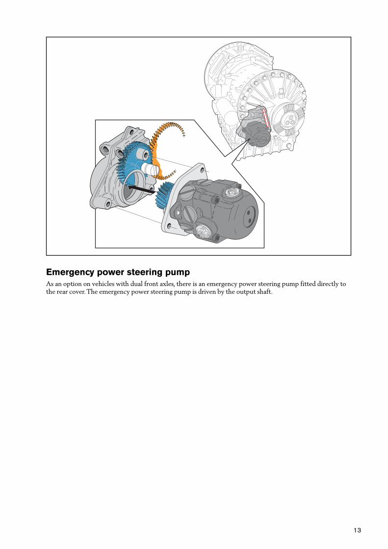
Emergency power steering pump
As an option on vehicles with dual front axles, there is an emergency power steering pump fitted directly tothe rear cover. The emergency power steering pump is driven by the output shaft.
14
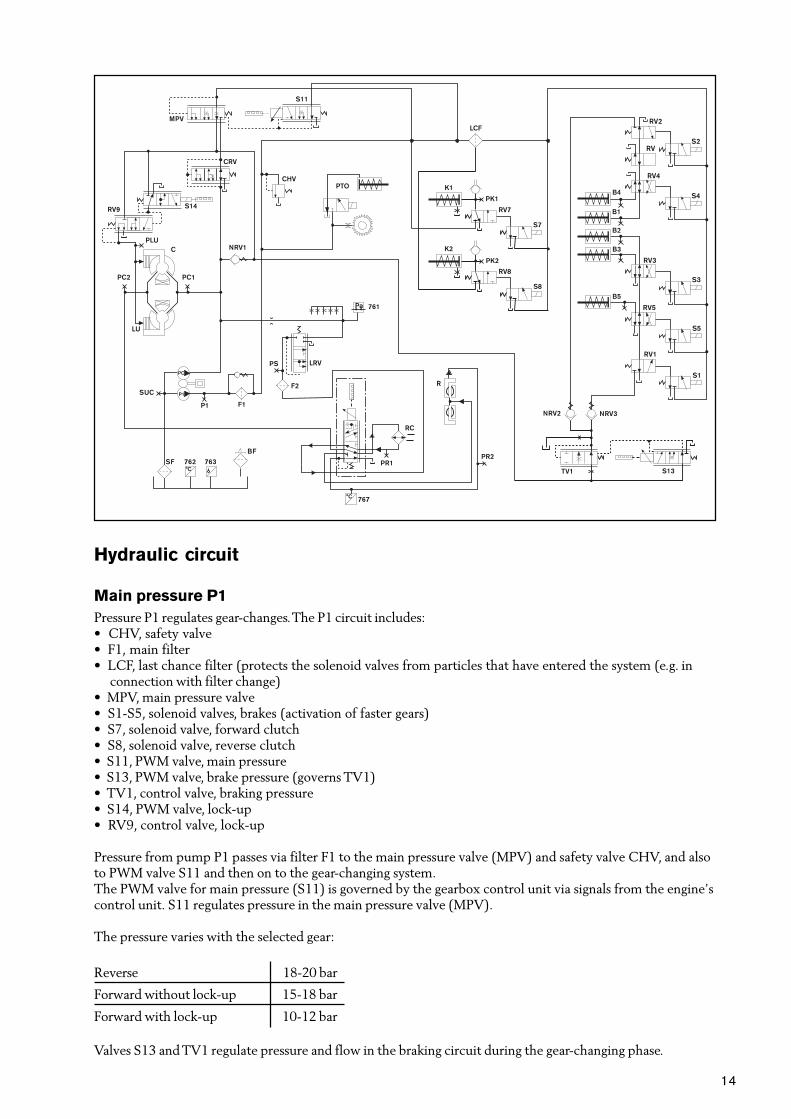
Hydraulic circuit
Main pressure P1
Pressure P1 regulates gear-changes. The P1 circuit includes:• CHV, safety valve• F1, main filter• LCF, last chance filter (protects the solenoid valves from particles that have entered the system (e.g. in
connection with filter change)• MPV, main pressure valve• S1-S5, solenoid valves, brakes (activation of faster gears)• S7, solenoid valve, forward clutch• S8, solenoid valve, reverse clutch• S11, PWM valve, main pressure• S13, PWM valve, brake pressure (governs TV1)• TV1, control valve, braking pressure• S14, PWM valve, lock-up• RV9, control valve, lock-up
Pressure from pump P1 passes via filter F1 to the main pressure valve (MPV) and safety valve CHV, and alsoto PWM valve S11 and then on to the gear-changing system.The PWM valve for main pressure (S11) is governed by the gearbox control unit via signals from the engine’scontrol unit. S11 regulates pressure in the main pressure valve (MPV).
The pressure varies with the selected gear:
Reverse 18-20 bar
Forward without lock-up 15-18 bar
Forward with lock-up 10-12 bar
Valves S13 and TV1 regulate pressure and flow in the braking circuit during the gear-changing phase.

15
Torque converter pressure PC
PC is the pressure for the torque converter, retarder and gearbox lubrication. The PC circuit includes:
• 761, lubricating oil sensor
• C, torque converter
• CRV, torque converter relay
• F2, lubricating oil filter
• LRV, lubricating oil valve
• MPV, main pressure valve
• PC, torque converter pump
• R, retarder
• RC, retarder oil cooler
• RRV, retarder engagement valve
The pump (PC) supplies the torque converter (C) and retarder (R) via the retarder valve (RRV) the gear-box’s lubrication points via RRV and the lubrication pressure valve (LRV).
An oil cooler (RC) is fitted to the RRV and there is a filter (F2) ahead of the LRV.
Pressure to the torque converter (PC1) is controlled by the valve (CRV) which also allows movement ofsurplus oil from the main pressure circuit once the required main pressure (P1) has been achieved.
There is a bypass hole which releases oil directly from the pump to the gearbox’s lubrication points. Thisensures an adequate supply of lubricating oil from the moment the engine starts. The oil-pressure sensor(761) is connected to lubricating oil pressure.
Lubrication
Oil pressure is used to lubricate all the bearings in the gearbox and this is monitored by the oil pressuresensor (761) and the temperature and level sensors (762/763), which are attached to the control system.Temperature sensor (767) for the retarder. Lubricating oil is also responsible for cooling the clutch plates.
Check-measurement of the gearbox’s oil pressure
Factory-fitted pressure sockets are available for:
P1 Main pressure
PC1 Torque converter pressure
PS Lubricating oil pressure
However, it is possible to check-measure all pressure in the gearbox by supplementing the pressure sockets.

16
1st gear (6-speed variant)
When the gear selector is in mode A or M and the vehicle is started in 1st gear, the following takes place:
TECU supplies voltage to pins 7, 22 and 25, which are linked to solenoid valves S7, S1 and S5. The solenoidvalves now activate forward clutch K1 and brake B5 via relay valves and hydraulic pistons.
K1 locks the turbine shaft in the mainshaft. B5 locks the planetary gear carrier in planetary gear 5 to thegearbox housing. 1st gear is thus engaged.
Solenoid valves – relay valves
S1Connects relay valve RV1 to increase oil pressure in the circuit for B5, B3 and B2 by filling with oil.
S5Connects RV5 to increase oil pressure in brake B5.
S7Engages RV7 to increase the oil pressure in forward clutch K1.
7 22 25
S7 S1 S5
TECU
GECU
K1
K2
RV7
RV8
S7
S8
NRV3
PK1
PK2
S1
RV1
S5
RV5RV5
B5

17
2nd gear (1st gear in 5-speed variant)
When 2nd gear is engaged, TECU supplies voltage to pins 23, 39 and 7. Solenoid valves S2, S4 and S7 are liveand activate forward clutch K1 and brake B4 via relay valves and hydraulic pistons. K1 locks turbine shaft (4)in the mainshaft (7). B4 locks the ring gear to planetary gear 4 in the gearbox housing.
K1 and B4 thus engage 2nd gear, or 1st gear if this is a 5-speed variant.
Solenoid valves – relay valves
S2Connects relay valve RV2 to increase oil pressure in the circuit for B4 and B1 by filling with oil.
S5Connects RV4 to increase oil pressure in brake B4.
S7Engages RV7 to increase the oil pressure in forward clutch K1.
K1
K2
RV7
RV8
S7
S8
B4
RV4
S4
RV
RV2
S2
PK1
PK2
23 39 7
S2 S4 S7
TECU
GECU
NRV2

18
3rd gear (2nd gear in 5-speed variant)
TECU supplies voltage to pins 22, 38 and 7. Solenoid valves S1, S3 and S7 are live and activate forwardclutch K1 and brake B3 via relay valves and hydraulic pistons. K1 locks turbine shaft (4) in the mainshaft (7).B3 locks the planetary gear carrier in planetary gear 2 in the gearbox housing. K1 and B3 thus engage 3rd gear,or 2nd gear if this is a 5-speed variant. The illustration shows how solenoid valves S1, S3 and S7 togetheractivate K1 and B3.
Solenoid valves – relay valves
S1Connects relay valve RV1 to increase oil pressure in the circuit for B5, B3 and B2 by filling with oil.
S3Connects RV3 to increase oil pressure in brake B3.
S7Engages RV7 to increase the oil pressure in forward clutch K1.
K1
K2
RV7
RV8
S7
S8NRV3
RV3
S3
B3
PK1
PK2
B5
RV5
S5
S1
RV1
22 38 7
S1 S3 S7
TECU
GECU

19
4th gear (3rd gear in 5-speed variant)
TECU supplies voltage to pins 23 and 7.Solenoid valves S2 and S7 are live and activate forward clutch K1 and brake B1 via relay valves and hydrau-lic pistons. K1 and brake B1 lock turbine shaft (4) in the mainshaft (7). B1 locks the planetary gear carrier inplanetary gear 1 in the gearbox housing. K1 and B1 thus engage 4th gear.
Solenoid valves – relay valves
S2Connects relay valve RV2 to increase oil pressure in the circuit for B1 by filling with oil. Since S4 is notactivated, pressure passes to B1.
S7Engages RV7 to increase the oil pressure in forward clutch K1.
K1
K2
RV7
RV8
S7
S8
B4
B1
RV4
S4
RV
RV2
S2
PK1
PK2
23 7
S2 S7
TECU
GECU
NRV2

20
5th gear (4th gear in 5-speed variant)
TECU supplies voltage to pins 22 and 7.Solenoid valves S1 and S7 are live and activate forward clutch K1 and brake B2 via relay valves and hydrau-lic pistons. K1 locks turbine shaft (4) in the mainshaft (7). B2 locks the sunwheel in planetary gear 1 in thegearbox housing. K1 and B2 thus engage 5th gear.
Solenoid valves – relay valves
S1Connects relay valve RV1 to increase oil pressure in the circuit for B5, B3 and B2 by filling with oil. Since S5and S3 are not activated, pressure passes to B2.
S7Engages RV7 to increase the oil pressure in forward clutch K1.
22 7
S1 S7
TECU
GECU
K1
K2
RV7
RV8
S7
S8
RV3
S3
B2
B3PK1
PK2
B5
S5
S1
RV1
RV5
NRV3

21
6th gear (5th gear in 5-speed variant)
TECU supplies voltage to pins 4 and 7.Solenoid valves S8 and S7 are live and activate forward clutch K1 and reverse clutch K2 via relay valves andhydraulic pistons. K1 locks turbine shaft (4) in the mainshaft (7). K2 locks the turbine shaft (4) to thetubular shaft (8). K1 and K2 lock the planetary gears so that all the planetary gears rotate as a single unit,giving a ratio of 1:1 in 6th gear.
Solenoid valves – relay valves
S7Engages RV7 to increase the oil pressure in forward clutch K1.
S8Engages relay valve RV8 to increase the oil pressure in reverse clutch K2.
K1
K2
RV7
S7
S8
PK1
PK2
RV8
4 7
S8 S7
TECU
GECU

22
Reverse gear R1
TECU supplies voltage to pins 22, 25 and 4.Solenoid valves S1, S5 and S8 are live and activate reverse clutch K2 and brake B5 via relay valves andhydraulic pistons.
The low reverse ratio is obtained when the turbine shaft’s moment is transferred via K2 and tubular shaft (8)to the sunwheel in planetary gear 2.
The planetary gear carrier in planetary gear 2 transfers the torque to the ring gear in planetary gear 3.
The planetary gears in planetary gear 3 function as idler wheels and reverse the direction of rotation on themainshaft (7).
The planetary gear carrier in planetary gear 5 is locked in the gearbox housing by B5.
This reverse gear is not found on the 5-speed variant.
Solenoid valves – relay valves
S1Connects relay valve RV1 to increase oil pressure in the circuit for B2, B3 and B5 by filling with oil.
S5Engages RV5 to increase the oil pressure in brake B4.
S8Engages relay valve RV8 to increase the oil pressure in forward clutch K1.
K1
K2
RV7
RV8
S7
S8
NRV3
PK1
PK2S1
RV1
S5
RV5RV5
B5
22 25 4
S1 S5 S8
TECU
GECU

23
Reverse gear R2 (reverse gear R on 5-speed variant)
TECU supplies voltage to pins 23, 39 and 4.Solenoid valves S2, S4 and S8 are live and activate reverse clutch K2 and brake B4 via relay valves andhydraulic pistons.
The high reverse ratio is obtained when the reverse clutch (K2) locks the turbine shaft (4) to the tubularshaft (8) and brake B4 locks the planetary gear carrier for planetary gear 3 to the gearbox housing.
Solenoid valves – relay valves
S2Engages relay valve RV2 to increase oil pressure in the circuit for B4 and B1 by filling with oil.
S4Engages RV4 to increase the oil pressure in brake B4.
S8Engages relay valve RV8 to increase the oil pressure in forward clutch K1.
23 39 4
S2 S4 S8
TECU
GECU
B4
RV4
S4
RV
RV2
S2
K1
K2
RV7
RV8
S7
S8
PK1
PK2
NRV2

24
Changing gear without power loss (Powershift)
The upper curve shows engine revs when changing gear. The lower curve shows hydraulic pressure in brakeB4 and brake B5.
When shifting between 1st and 2nd gear, pressure in B5 drops at the same time as it rises in B4. The gear-changing sequence in this example takes about 0.4 seconds.
In 0.4 seconds, B4 brakes the ring gear in planetary gear 4 to standstill.
Gear-change takes place without any loss of power, and this process is called Powershift.

25
M
EP
K B
������� ���
E 4A
�
�
�
���� ��
Gear selector and display
Using the gear selector, the driver can choose between two programmes for driving forwards, as well asneutral and reverse.
R Reverse gear
N Neutral
A Automatic mode
M Manual mode
On the gear selector housing there are two push-buttons marked E/P and 2/1 (2/1 is only found on the 6-speed variant). Button 2/1 is used to choose between 1st and 2nd gear as the starting gear.
E Economy programme for lower fuel consumption.
P Power programme, useful in operations requiring high engine output.
C Changes up take place at higher engine revs.
2 The truck starts off in 2nd gear when driving forwards, and R2 in reverse.
1 The truck starts off in 1st gear when driving forwards, and R1 in reverse.

26
Automatic mode (A)
Gear-changes take place entirely automatically using the information which the gearbox control unit (TECU)receives from the various control units and from the gearbox’s various sensors.
If the accelerator pedal is pressed down completely, this produces a kick-down effect.
Kick-down is used to obtain maximum engine power, for instance when overtaking.
If the selector is moved to (M) while driving in the automatic mode (A), further gear-changes will be pre-vented and the currently selected gear will be held throughout the engine’s operating range.
The E/P button is used only in automatic mode.
The E/P button switches between Economy and Power modes.
Manual mode (M)
On the gear selector handle, there is a spring-loaded three-way switch marked and , with a neutralposition in between.
Gear-changes take place manually by pressing (up) or (down) in a sequence of 5 or 6 stages, dependingon the type of gearbox fitted.
Display
The display unit in the instrument panel informs the driver about how the gearbox is working, and alerts himif there are any faults in the system.
Gear selector position/control function A B C
Reverse R 1-2
Neutral N
Automatic mode A 1-6
Manual mode M 1-6
(up) Possible no. of changes up
(down) Possible no. of changes down
E/ Economy program E
/P Power program P
2 / 1st gear blocked, start in 2nd and R2 reverse 2
/1 Start in 1st forwards and R1 reverse 1
Torque converter engaged C
Kick-down activated K
Engine revs too high to leave neutral Z
Indicates that increased aux. brake power is chosen B
Limp Home L

27
”Limp Home”
The Powertronic system is equipped with a ”limp home” function, that makes it possible to drive the vehicleeven if there is a fault in the control link (SAE J1939).
If the transmission control unit (TECU) or the engine (EECU) is disconnected from the control link, thenthe ”Limp home” function is engaged automatically. When the “Limp home” mode is activated it is shownwithin the display as an “ L “
When the system is running in “Limp home” mode the system uses the information link (SAE J1708) to sendnecessary signals.
Gear shifting in “Limp home” mode can only be done manually and under particular conditions.Up and down shift can only take place if the engine torque is less then 500 Nm, and during down shift it isalso a condition that the engine retarder torque is less then 500 Nm.That means that the accelerator pedal has to be released, so that the engine torque goes down, before gearchanging can take place.
Using the up/down switch, with the gear selector in manual position does gear changing.
Automatic gear shifting only takes place as a protection for the engine or the turbine. The brake programdoes not work in limp home mode.
If the system receive correct signals from the control link (J1939) for more then 2 seconds, the systemreturns back to normal mode.
������� ���
L 4M
���� ��

28
Component location

29
Power transmission
1 Pump wheel
2 Turbine wheel
2 Guide wheel
3 Turbine shaft
4 Forward clutch (K1)
5 Reverse clutch (K2)
6 Mainshaft
7 Tubular shaft
8 Output shaft
9 Lock-up clutch
A Control system
B Oil pump
C Torque converter
D Retarder
E Power take-off (6024)
Clutches and brakes in the transmission
B1 4th gear (3rd in 5-speed box)
B2 5th gear (4th in 5-speed box)
B3 3rd gear (2nd in 5-speed box)
B4 2nd gear (1st in 5-speed box)
B5 1st gear
K1 Forward clutch, direct ratio
K2 Reverse clutch, direct ratio
Sensors and solenoid valves in the transmission system
758 Rev sensor, output shaft, for control unit
761 Sensor, gearbox oil pressure
762 Sensor, gearbox oil temperature
763 Sensor, gearbox oil level
767 Sensor, retarder oil temperature
6018 PWM valve, retarder
7052 Sensor, tachograph/speedometer
7070 Sensor, engine speed
7076 Sensor, turbine speed, torque converter
S1-S5 Solenoid valves, brakes (engagement of faster gears)
S7 Solenoid valve, forward clutch
S8 Solenoid valve, reverse clutch, 6th speed forwards
S14 PWM valve, Lock-up
S11 PWM valve, main clutch pressure
S13 PWM valve, brake pressure

30
Solenoid valves

31
Hydraulic diagram

32
Components
761 Sensor, gearbox oil pressure
762 Sensor, gearbox oil temperature
763 Sensor, gearbox oil level
767 Sensor, retarder oil temperature
B1-B5 Brakes
BF Ventilation filter
C Torque converter
CHV Safety valve
CRV Torque converter pressure valve
F1 Main oil filter
F2 Lubrication oil filter
K1 Forward clutch, direct ratio
K2 Reverse clutch, direct ratio
LCF Last Chance Filter
LRV Lubricating oil pressure valve
LU Lock-Up
MPV Main pressure valve
NRV1 Non-return valve
NRV2 Non-return valve
NRV3 Non-return valve
P1 Pump, control system
PC Pump, torque converter (see also pressure socket/pressure)
PTO Power take-off
R Retarder
RC Oil cooler, retarder
RRV Activation valve, retarder
RV Relay valve, reserve
RV1-RV5 Relay valves, gear engagement
RV7 Relay valve, forward clutch
RV8 Relay valve, reverse clutch
RV9 Relay valve, Lock-up
S1-S5 Solenoid valves, brakes (activation of faster gears)
S7 Solenoid valve, forward clutch
S8 Solenoid valve, reverse clutch
S11 PWM valve, main clutch pressure
S13 PWM valve, braking pressure
S14 PWM valve, direct coupling (Lock-Up)
SF Suction filter
TV1 Control valve, braking pressure

33
Pressure sockets/pressure
B1-B5 Engagement pressure, brakes
PK1 Engagement pressure, forward ratio
PK2 Engagement pressure, reverse gear, top gear forwards
P1 Main pressure
PC1 Torque converter pressure IN
PC2 Torque converter pressure OUT


![PowerTRONIC Installation Manual Royal Enfield Classic 500 ... · PowerTRONIC Installation Manual Royal Enfield Classic 500 [Twin Spark] EFI (2009-2019) D o c u m e n t V e r s i o](https://static.fdocuments.in/doc/165x107/5e72c4638370205112736b21/powertronic-installation-manual-royal-enfield-classic-500-powertronic-installation.jpg)


