Powertrain System of Honda FCX Clarity Fuel Cell … Stavanger, Norway, May 13-16, 2009 Powertrain...
10
EVS24 Stavanger, Norway, May 13-16, 2009 Powertrain System of Honda FCX Clarity Fuel Cell Vehicle Minoru MATSUNAGA 1 , Tatsuya FUKUSHIMA 1 , Kuniaki OJIMA 1 1 Honda R&D Co., Ltd., 4630 Shimotakanezawa, Haga-machi, Haga-gun, Tochigi, Japan, [email protected] , [email protected] , [email protected] Abstract To assist in combating global warming and to respond to energy issues, Honda has developed the FCX Clarity, a new fuel cell vehicle that displays significant improvements in driving performance and fuel efficiency against previous FCX Models, and which achieves a level of appeal unrivalled by reciprocating engine vehicles. The key to the development of the new vehicle was the reduction of the size and weight of the fuel cell powertrain. Honda’s unique V Flow FC stack technology is the core of the FCX Clarity’s fuel cell powertrain. A considerable reduction in size and weight and increased power have been achieved, with the powertrain as a whole displaying a weight output density that is 2X higher and volume output density 2.2X higher than that of the previous FCX. The maximum power of the V Flow FC stack employed in the Clarity has been increased to 100 kW. The new FC stack also achieves a 50% increase in volume output density and 67% increase in weight output density against the previous stack. Low-temperature start performance has also been significantly improved, with the vehicle able to be started at -30 °C. A new design has increased the maximum power of the drive motor to 100 kW and resulted in the achievement of a smooth, powerful and continuously extendable acceleration feel. Increased efficiency in the powertrain and superior energy management have enabled the realization of an energy efficiency of 60%, resulting in a level of fuel efficiency 2.1X higher than that of a small gasoline vehicle and 1.4X higher than that of a small hybrid vehicle. Keywords: Fuel cell electric vehicle, Powertrain, Performance 1 Introduction Honda first introduced the environmentally- friendlier FCX fuel cell vehicle to the Japanese and U.S. markets in 2002 [1]. In 2004, the company developed an FCX vehicle fitted with a fuel cell (FC) stack able to be started at –20 °C, enabling the vehicle to be used in cold climates [2], [3]. The enhancements in driving performance and environmental performance, which have been sought in the development of the FCX, mean that the vehicle is now able to compete with a EVS24 International Battery, Hybrid and Fuel Cell Electric Vehicle Symposium 1 World Electric Vehicle Journal Vol. 3 - ISSN 2032-6653 - © 2009 AVERE Page 0820
Transcript of Powertrain System of Honda FCX Clarity Fuel Cell … Stavanger, Norway, May 13-16, 2009 Powertrain...

EVS24 Stavanger, Norway, May 13-16, 2009
Powertrain System of Honda FCX Clarity Fuel Cell Vehicle
Minoru MATSUNAGA 1, Tatsuya FUKUSHIMA 1, Kuniaki OJIMA 1
1 Honda R&D Co., Ltd., 4630 Shimotakanezawa, Haga-machi, Haga-gun, Tochigi, Japan, [email protected], [email protected], [email protected]
Abstract To assist in combating global warming and to respond to energy issues, Honda has developed the FCX
Clarity, a new fuel cell vehicle that displays significant improvements in driving performance and fuel
efficiency against previous FCX Models, and which achieves a level of appeal unrivalled by reciprocating
engine vehicles. The key to the development of the new vehicle was the reduction of the size and weight of
the fuel cell powertrain.
Honda’s unique V Flow FC stack technology is the core of the FCX Clarity’s fuel cell powertrain. A
considerable reduction in size and weight and increased power have been achieved, with the powertrain as
a whole displaying a weight output density that is 2X higher and volume output density 2.2X higher than
that of the previous FCX.
The maximum power of the V Flow FC stack employed in the Clarity has been increased to 100 kW. The
new FC stack also achieves a 50% increase in volume output density and 67% increase in weight output
density against the previous stack. Low-temperature start performance has also been significantly improved,
with the vehicle able to be started at -30 °C.
A new design has increased the maximum power of the drive motor to 100 kW and resulted in the
achievement of a smooth, powerful and continuously extendable acceleration feel.
Increased efficiency in the powertrain and superior energy management have enabled the realization of an
energy efficiency of 60%, resulting in a level of fuel efficiency 2.1X higher than that of a small gasoline
vehicle and 1.4X higher than that of a small hybrid vehicle.
Keywords: Fuel cell electric vehicle, Powertrain, Performance
1 Introduction Honda first introduced the environmentally-friendlier FCX fuel cell vehicle to the Japanese and U.S. markets in 2002 [1]. In 2004, the company developed an FCX vehicle fitted with a
fuel cell (FC) stack able to be started at –20 °C, enabling the vehicle to be used in cold climates [2], [3]. The enhancements in driving performance and environmental performance, which have been sought in the development of the FCX, mean that the vehicle is now able to compete with a
EVS24 International Battery, Hybrid and Fuel Cell Electric Vehicle Symposium 1
World Electric Vehicle Journal Vol. 3 - ISSN 2032-6653 - © 2009 AVERE
Page 0820

reciprocating engine vehicle in terms of performance. The FCX fuel cell powertrain was subject to a thoroughgoing re-examination in order to achieve a further evolution of the vehicle’s performance and to increase its commercial appeal. This re-examination indicated that the reduction of the size of the powertrain would be the key to enabling maximal exploitation of the high degree of freedom in layout, which is one of the major characteristics of the fuel cell system. The result of the development of an all-new powertrain for the FCX has been the debut of the FCX Clarity, the new model fuel cell vehicle that is introduced in this paper. The Clarity’s unique design gives it an interior and controls with a futuristic feel, and it features a roomy cabin for a compact vehicle. Boasting a driving range equalling that of a reciprocating engine vehicle, the Clarity offers a drive feel unavailable from a reciprocating engine. Driving distance and refuel time are issues that fuel cell vehicles share with vehicles using electric drives, and this paper will also compare the Clarity’s performance in these areas with that of an electric vehicle, based on the latest battery technology.
2 Development Objectives The following development objectives were established in order to manifest the new commercial appeal and new value that is able to be realized by the FCX Clarity, because it employs a fuel cell powertrain: (1) Realization of an appealing vehicle design
An all-new exterior and interior design making use of the degree of freedom in layout afforded by the use of a fuel cell powertrain
A cockpit offering a new sensory experience – like driving a vehicle of the future
(2) Realization of the full cabin space available only in a fuel cell vehicle
Short and slanted nose Spacious cabin Low floor, low overall cabin height Functional trunk space
(3) Enhanced basic vehicle performance Smooth, powerful, continuously extendable acceleration feel
Vehicle range equal to that of a reciprocating engine vehicle
Enhanced low-temperature start-up performance
3 Vehicle Design and Interior Equipments
3.1 Vehicle Design Figure 1 shows the exterior of the FCX Clarity. Fuel cell vehicles up to the present have mainly employed an SUV platform, with the electric generating system positioned under the floor. The design of the FCX Clarity sought to take advantage of the freedom in layout that is a major feature of fuel cell vehicle packages, and to realize the type of layout that is only possible in fuel cell vehicle. The result is a revolutionary low-floor sedan platform incorporating unique interior and exterior designs. A high deck design has been employed for the rear of the vehicle. The world-first extra window for vehicles has a visibility control function enabling the achievement of good rear visibility for the driver to be reconciled with the restriction of visibility from outside the vehicle into the trunk space. This has enabled the realization of both good rear visibility and a roomy trunk. The color of the vehicle exterior is a special tint based on the semiprecious gemstone star garnet. Table 1 shows the major specifications of the FCX
Table 1: Major specifications
Model FCX Clarity 2005 FCX Length/Width/
Height 4845x1845 x1470mm
4165x1760 x1645mm
Wheel base 2800 mm 2530 mm Vehicle weight 1625 kg 1670 kg
Number of passengers 4 4
Maximum speed 160 km/h 150 km/h Range (EPA
combined label) 280 mile 210 mile
Maximum motorpower 100 kW 80 kW
Maximum motortorque 256 Nm 272 Nm
Fuel cell stack PEMFC PEMFC
Power assist Li-ion battery Ultra-capacitor
Hydrogen supplysystem
High-pressure hydrogen tank
High-pressure hydrogen tank
Hydrogen pressure 35 MPa 34.4 MPa
Hydrogen storagevolume 171 L 156.6 L
EVS24 International Battery, Hybrid and Fuel Cell Electric Vehicle Symposium 2
World Electric Vehicle Journal Vol. 3 - ISSN 2032-6653 - © 2009 AVERE
Page 0821
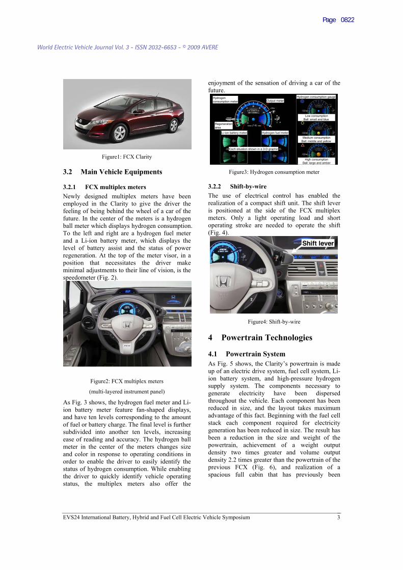
Figure1: FCX Clarity
3.2 Main Vehicle Equipments
3.2.1 FCX multiplex meters Newly designed multiplex meters have been employed in the Clarity to give the driver the feeling of being behind the wheel of a car of the future. In the center of the meters is a hydrogen ball meter which displays hydrogen consumption. To the left and right are a hydrogen fuel meter and a Li-ion battery meter, which displays the level of battery assist and the status of power regeneration. At the top of the meter visor, in a position that necessitates the driver make minimal adjustments to their line of vision, is the speedometer (Fig. 2).
Figure2: FCX multiplex meters
(multi-layered instrument panel)
As Fig. 3 shows, the hydrogen fuel meter and Li-ion battery meter feature fan-shaped displays, and have ten levels corresponding to the amount of fuel or battery charge. The final level is further subdivided into another ten levels, increasing ease of reading and accuracy. The hydrogen ball meter in the center of the meters changes size and color in response to operating conditions in order to enable the driver to easily identify the status of hydrogen consumption. While enabling the driver to quickly identify vehicle operating status, the multiplex meters also offer the
enjoyment of the sensation of driving a car of the future.
Hydrogenconsumption meter Output meter
Regenerationarea
Li-ion battery meter Hydrogen fuel meter
Hydrogen consumption gauge
High consumptionBall: large and amber
Low consumptionBall: small and blue
Medium consumptionBall: middle and yellow
Each situation shown in a 3-D graphic
Hydrogenconsumption meter Output meter
Regenerationarea
Li-ion battery meter Hydrogen fuel meter
Hydrogen consumption gauge
High consumptionBall: large and amber
Low consumptionBall: small and blue
Medium consumptionBall: middle and yellow
Each situation shown in a 3-D graphic
Figure3: Hydrogen consumption meter
3.2.2 Shift-by-wire The use of electrical control has enabled the realization of a compact shift unit. The shift lever is positioned at the side of the FCX multiplex meters. Only a light operating load and short operating stroke are needed to operate the shift (Fig. 4).
Shift leverShift lever
Figure4: Shift-by-wire
4 Powertrain Technologies
4.1 Powertrain System As Fig. 5 shows, the Clarity’s powertrain is made up of an electric drive system, fuel cell system, Li-ion battery system, and high-pressure hydrogen supply system. The components necessary to generate electricity have been dispersed throughout the vehicle. Each component has been reduced in size, and the layout takes maximum advantage of this fact. Beginning with the fuel cell stack each component required for electricity generation has been reduced in size. The result has been a reduction in the size and weight of the powertrain, achievement of a weight output density two times greater and volume output density 2.2 times greater than the powertrain of the previous FCX (Fig. 6), and realization of a spacious full cabin that has previously been
EVS24 International Battery, Hybrid and Fuel Cell Electric Vehicle Symposium 3
World Electric Vehicle Journal Vol. 3 - ISSN 2032-6653 - © 2009 AVERE
Page 0822
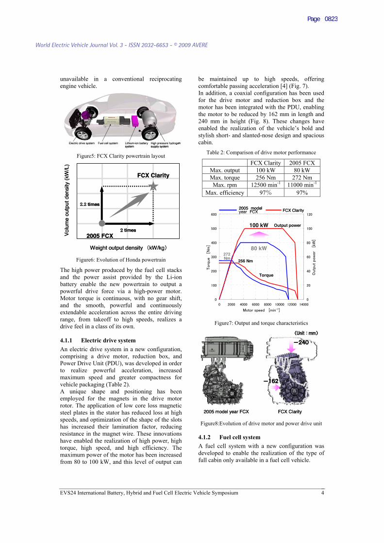
unavailable in a conventional reciprocating engine vehicle.
Lithium-ion batterysystem
High pressure hydrogensupply system
Fuel cell systemElectric drive system Lithium-ion batterysystem
High pressure hydrogensupply system
Fuel cell systemElectric drive system
Figure5: FCX Clarity powertrain layout
times
Weight output density kW/kg
Vol
ume
outp
ut d
ensi
ty (
kW/L
)
2005 FCX
FCX Clarity
times
times
Weight output density kW/kg
Vol
ume
outp
ut d
ensi
ty (
kW/L
)
2005 FCX
FCX Clarity
times
Figure6: Evolution of Honda powertrain
The high power produced by the fuel cell stacks and the power assist provided by the Li-ion battery enable the new powertrain to output a powerful drive force via a high-power motor. Motor torque is continuous, with no gear shift, and the smooth, powerful and continuously extendable acceleration across the entire driving range, from takeoff to high speeds, realizes a drive feel in a class of its own.
4.1.1 Electric drive system An electric drive system in a new configuration, comprising a drive motor, reduction box, and Power Drive Unit (PDU), was developed in order to realize powerful acceleration, increased maximum speed and greater compactness for vehicle packaging (Table 2). A unique shape and positioning has been employed for the magnets in the drive motor rotor. The application of low core loss magnetic steel plates in the stator has reduced loss at high speeds, and optimization of the shape of the slots has increased their lamination factor, reducing resistance in the magnet wire. These innovations have enabled the realization of high power, high torque, high speed, and high efficiency. The maximum power of the motor has been increased from 80 to 100 kW, and this level of output can
be maintained up to high speeds, offering comfortable passing acceleration [4] (Fig. 7). In addition, a coaxial configuration has been used for the drive motor and reduction box and the motor has been integrated with the PDU, enabling the motor to be reduced by 162 mm in length and 240 mm in height (Fig. 8). These changes have enabled the realization of the vehicle’s bold and stylish short- and slanted-nose design and spacious cabin.
Table 2: Comparison of drive motor performance
FCX Clarity 2005 FCXMax. output 100 kW 80 kW Max. torque 256 Nm 272 Nm Max. rpm 12500 min-1 11000 min-1
Max. efficiency 97 97%
100 kW Output power
80 kW
Torque
272Nm
256 Nm
FCX Clarityyear FCX2005 model
100 kW100 kW Output powerOutput power
80 kW80 kW
TorqueTorque
272Nm272Nm
256 Nm256 Nm
FCX Clarityyear FCX2005 model
Figure7: Output and torque characteristics
2005 model year FCX FCX Clarity2005 model year FCX FCX Clarity
Figure8:Evolution of drive motor and power drive unit
4.1.2 Fuel cell system A fuel cell system with a new configuration was developed to enable the realization of the type of full cabin only available in a fuel cell vehicle.
EVS24 International Battery, Hybrid and Fuel Cell Electric Vehicle Symposium 4
World Electric Vehicle Journal Vol. 3 - ISSN 2032-6653 - © 2009 AVERE
Page 0823
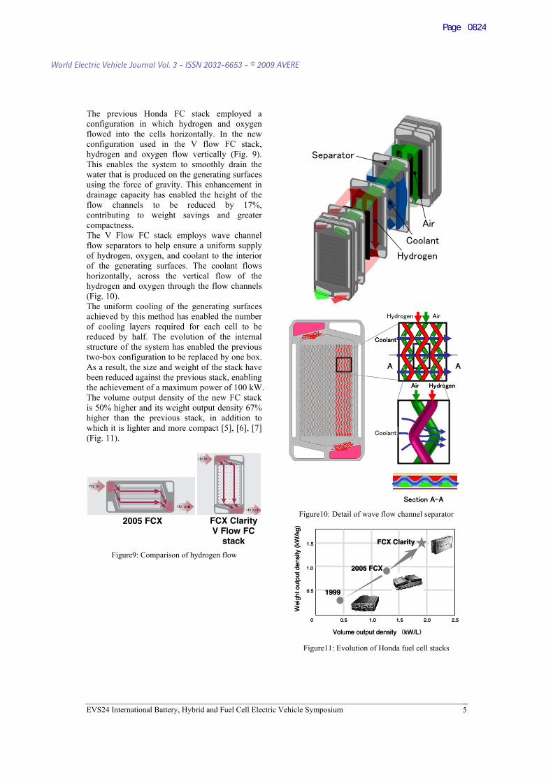
The previous Honda FC stack employed a configuration in which hydrogen and oxygen flowed into the cells horizontally. In the new configuration used in the V flow FC stack, hydrogen and oxygen flow vertically (Fig. 9). This enables the system to smoothly drain the water that is produced on the generating surfaces using the force of gravity. This enhancement in drainage capacity has enabled the height of the flow channels to be reduced by 17%, contributing to weight savings and greater compactness.
The V Flow FC stack employs wave channel flow separators to help ensure a uniform supply of hydrogen, oxygen, and coolant to the interior of the generating surfaces. The coolant flows horizontally, across the vertical flow of the hydrogen and oxygen through the flow channels (Fig. 10). The uniform cooling of the generating surfaces achieved by this method has enabled the number of cooling layers required for each cell to be reduced by half. The evolution of the internal structure of the system has enabled the previous two-box configuration to be replaced by one box. As a result, the size and weight of the stack have been reduced against the previous stack, enabling the achievement of a maximum power of 100 kW. The volume output density of the new FC stack is 50% higher and its weight output density 67% higher than the previous stack, in addition to which it is lighter and more compact [5], [6], [7] (Fig. 11).
Figure9: Comparison of hydrogen flow
Figure10: Detail of wave flow channel separator FCX Clarity 2005 FCX V Flow FC
stack
Volume output density kW/L
Wei
ght o
utpu
t den
sity
(kW
/kg)
1999
FCX Clarity
0 0.5 1.0 1.5 2.0 2.5
0.5
1.0
1.5
2005 FCX
Volume output density kW/L
Wei
ght o
utpu
t den
sity
(kW
/kg)
1999
FCX Clarity
0 0.5 1.0 1.5 2.0 2.5
0.5
1.0
1.5
2005 FCX
Figure11: Evolution of Honda fuel cell stacks
EVS24 International Battery, Hybrid and Fuel Cell Electric Vehicle Symposium 5
World Electric Vehicle Journal Vol. 3 - ISSN 2032-6653 - © 2009 AVERE
Page 0824
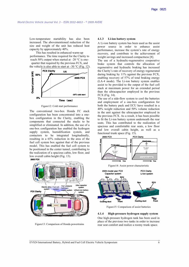
Low-temperature startability has also been increased. The abovementioned reduction of the size and weight of the unit has reduced heat capacity by approximately 40%.
This has resulted in enhanced warm-up performance. The time required for the Clarity to reach 50% output when started at –20 °C is one-quarter that required by the previous FCX, and
the vehicle is also able to start at –30 °C (Fig. 12).
Time sec
Ou
tpu
t p
ow
er (
kW)
0%
50%
-20 cold start
1/4FCX Clarity
2005 FCX
Time sec
Ou
tpu
t p
ow
er (
kW)
0%
50%
-20 cold start
1/4FCX Clarity
2005 FCX
Figure12: Cold start performance
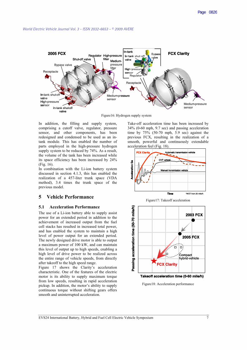
The conventional two-box Honda FC stack configuration has been concentrated into a one-box configuration in the Clarity, enabling the components that connected the stacks to be simplified or eliminated. In addition, the use of a one-box configuration has enabled the hydrogen supply system, humidification system, and contactors to be integrated longitudinally, resulting in a 65% reduction in the area of the fuel cell system box against that of the previous model. This has enabled the fuel cell system to be positioned in the center tunnel, contributing to the realization of a spacious cabin, low floor, and low overall cabin height (Fig. 13). 2005 FCX
FCX ClarityLithium-ion battery
system
High pressure hydrogensupply system
Fuel cell system
Electric drivesystem
Ultra capacitorsystem
2005 FCX
FCX ClarityLithium-ion battery
system
High pressure hydrogensupply system
Fuel cell system
Electric drivesystem
Ultra capacitorsystem
Figure13: Comparison of Honda powertrains
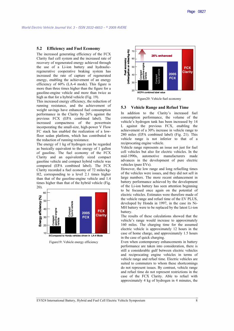
4.1.3 Li-ion battery system A Li-ion battery system has been used as the assist power source in order to enhance assist performance, increase the system’s rate of energy recovery, and contribute to the achievement of weight savings and increased compactness [8]. The use of a hydraulic-regenerative cooperative brake system that controls the allocation of regenerative and hydraulic braking has increased the Clarity’s rate of recovery of energy regenerated during braking by 11% against the previous FCX, enabling recovery of 57% of total braking energy (LA-4 mode). The Li-ion battery system enables assist to be provided to the output of the fuel cell stack at maximum power for an extended period than the ultracapacitor employed in the previous FCX (Fig. 14). The use of a side-flow system to cool the batteries and employment of a one-box configuration for both the battery pack and ECU have resulted in a 40% weight reduction and 50% volume reduction in the unit against the ultracapacitor employed in the previous FCX. As a result, it has been possible to fit the Li-ion battery system underneath the rear seats. This has contributed to the realization of spacious and comfortable rear seats, a low floor and low overall cabin height, as well as a functional trunk space (Fig. 15).
Overall output
Overall output
power power
Overall output
Overall output
power power
FCX Clarity2005 FCX
Overall output
Overall output
power power
Overall output
Overall output
power power
FCX Clarity2005 FCX
Figure14: Assist power characteristic
ECUBox
Cooling duct FrontFront
FCX Clarity2005 model year FCX
ECUBox
Cooling duct
Li-ion systemCapacitor system
ECUBox
Cooling duct FrontFront
FCX Clarity2005 model year FCX
ECUBox
Cooling duct
Li-ion systemCapacitor system
Figure15: Comparison of assist batteries
4.1.4 High-pressure hydrogen supply system One high-pressure hydrogen tank has been used in place of the previous two tanks in order to increase rear seat comfort and realize a roomy trunk space.
EVS24 International Battery, Hybrid and Fuel Cell Electric Vehicle Symposium 6
World Electric Vehicle Journal Vol. 3 - ISSN 2032-6653 - © 2009 AVERE
Page 0825
EVS24 International Battery, Hybrid and Fuel Cell Electric Vehicle Symposium 7
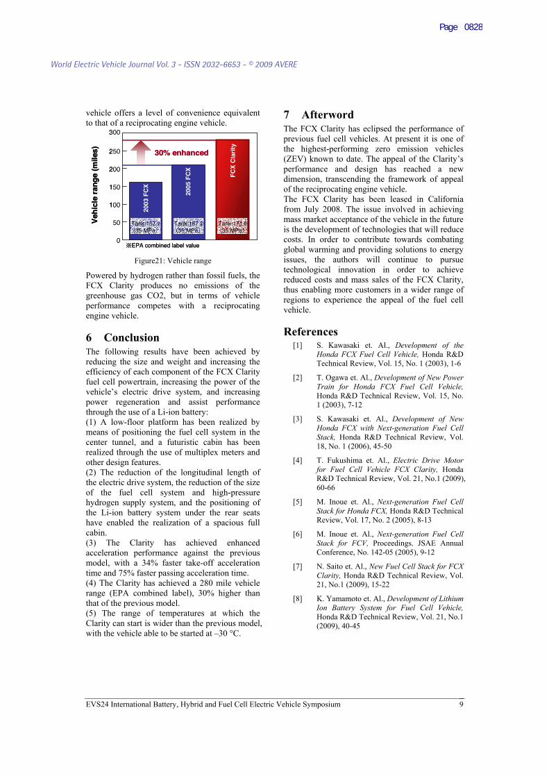
In addition, the filling and supply system, comprising a cutoff valve, regulator, pressure sensor, and other components, has been redesigned and condensed to be used as an in-tank module. This has enabled the number of parts employed in the high-pressure hydrogen supply system to be reduced by 74%. As a result, the volume of the tank has been increased while its space efficiency has been increased by 24% (Fig. 16). In combination with the Li-ion battery system discussed in section 4.1.3, this has enabled the realization of a 457-liter trunk space (VDA method), 3.4 times the trunk space of the previous model.
5 Vehicle Performance
5.1 Acceleration Performance The use of a Li-ion battery able to supply assist power for an extended period in addition to the achievement of increased output from the fuel cell stacks has resulted in increased total power, and has enabled the system to maintain a high level of power output for an extended period. The newly designed drive motor is able to output a maximum power of 100 kW, and can maintain this level of output up to high speeds, enabling a high level of drive power to be realized across the entire range of vehicle speeds, from directly after takeoff to the high speed range. Figure 17 shows the Clarity’s acceleration characteristic. One of the features of the electric motor is its ability to supply maximum torque from low speeds, resulting in rapid acceleration pickup. In addition, the motor’s ability to supply continuous torque without shifting gears offers smooth and uninterrupted acceleration.
Take-off acceleration time has been increased by 34% (0-60 mph, 9.7 sec) and passing acceleration time by 75% (50-70 mph, 5.9 sec) against the previous FCX, resulting in the realization of a smooth, powerful and continuously extendable acceleration feel (Fig. 18).
Manual transmission vehicle
CVT vehicle
Automatic transmission vehicleFCX Clarity
Time
Acc
eler
atio
n G
s
*WOT from 25 mile/h
Manual transmission vehicle
CVT vehicle
Automatic transmission vehicleFCX Clarity
Time
Acc
eler
atio
n G
s
Manual transmission vehicle
CVT vehicle
Automatic transmission vehicleFCX Clarity
Time
Acc
eler
atio
n G
s
*WOT from 25 mile/h Figure17: Takeoff acceleration
Takeoff acceleration time (0-60 mile/h)
Pas
sin
g a
ccel
erat
ion
tim
e (5
0-70
mile
/h)
2005 FCX
FCX Clarity
2003 FCX
Compact hybrid-vehicle
Takeoff acceleration time (0-60 mile/h)
Pas
sin
g a
ccel
erat
ion
tim
e (5
0-70
mile
/h)
2005 FCX
FCX Clarity
2003 FCX
Compact hybrid-vehicle
Figure18: Acceleration performance
Receptacle
Medium - pressuresensor
In - tank shut off -valve
In - tank shut - off valve
Regulator High-pressurefilterShut-off valve
Medium-pressurefilter
Medium-pressuresensor
High - pressure sensor
Receptacle
Bypass valve
In-tank module2005 FCX FCX Clarity
Receptacle
Medium - pressuresensor
In - tank shut off -valve
In - tank shut - off valve
Regulator High-pressurefilterShut-off valve
Medium-pressurefilter
Medium-pressuresensor
High - pressure sensor
Receptacle
Bypass valve
In-tank module2005 FCX FCX Clarity
Figure16: Hydrogen supply system
World Electric Vehicle Journal Vol. 3 - ISSN 2032-6653 - © 2009 AVERE
Page 0826
5.2 Efficiency and Fuel Economy
20
Fu
el e
con
om
y(m
iles/
gal
lon
or
mile
s/kg
-H2)
30
40
50
60
70
EPA combined label value
26% enhanced
FCXClarityv
Com
pact
gaso
line-
engi
neve
hicl
e
Com
pact
hve
hicl
e
2005FCX
20
Fu
el e
con
om
y(m
iles/
gal
lon
or
mile
s/kg
-H2)
30
40
50
60
70
EPA combined label value
26% enhanced
FCXClarityv
Com
pact
gaso
line-
engi
neve
hicl
e
Com
pact
hve
hicl
e
2005FCX
The increased generating efficiency of the FCX Clarity fuel cell system and the increased rate of recovery of regenerated energy achieved through the use of a Li-ion battery and hydraulic-regenerative cooperative braking system has increased the rate of capture of regenerated energy, enabling the achievement of an energy efficiency of 60% (LA-4 mode). This figure is more than three times higher than the figure for a gasoline-engine vehicle and more than twice as high as that for a hybrid vehicle (Fig. 19). This increased energy efficiency, the reduction of running resistance, and the achievement of weight savings have enhanced fuel consumption performance in the Clarity by 26% against the previous FCX (EPA combined label). The increased compactness of the powertrain incorporating the small-size, high-power V Flow FC stack has enabled the realization of a low-floor sedan platform, which has contributed to the reduction of running resistance. The energy of 1 kg of hydrogen can be regarded as basically equivalent to the energy of 1 gallon of gasoline. The fuel economy of the FCX Clarity and an equivalently sized compact gasoline vehicle and compact hybrid vehicle was compared (EPA combined label). The FCX Clarity recorded a fuel economy of 72 miles/kg-H2, corresponding to a level 2.1 times higher than that of the gasoline-engine vehicle and 1.4 times higher than that of the hybrid vehicle (Fig. 20).
60
10
FCXClarity
En
erg
y ef
fici
ency
(%
)
2005FCX
Compared to Honda vehicles driven in LA-4 Mode
Com
pact
gaso
line-
engi
neve
hicl
e
Com
pact
hve
hicl
e
20
30
40
50
60
10
FCXClarity
En
erg
y ef
fici
ency
(%
)
2005FCX
Compared to Honda vehicles driven in LA-4 Mode
Com
pact
gaso
line-
engi
neve
hicl
e
Com
pact
hve
hicl
e
20
30
40
50
Figure19: Vehicle energy efficiency
Figure20: Vehicle fuel economy
5.3 Vehicle Range and Refuel Time In addition to the Clarity’s increased fuel consumption performance, the volume of the vehicle’s hydrogen tank has been increased by 14 L against the previous FCX, enabling the achievement of a 30% increase in vehicle range to 280 miles (EPA combined label) (Fig. 21). This vehicle range is not inferior to that of a reciprocating engine vehicle. Vehicle range represents an issue not just for fuel cell vehicles but also for electric vehicles. In the mid-1990s, automotive manufacturers made advances in the development of pure electric vehicles (pure EVs). However, the low range and long refuelling times of the vehicles were issues, and they did not sell in large numbers. The more recent enhancement in battery performance achieved by the development of the Li-ion battery has seen attention beginning to be focused once again on the potential of electric vehicles. Estimates were therefore made of the vehicle range and refuel time of the EV PLUS, developed by Honda in 1997, in the case its Ni-MH battery were to be replaced by the latest Li-ion battery. The results of these calculations showed that the vehicle’s range would increase to approximately 160 miles. The charging time for the assumed electric vehicle is approximately 12 hours in the case of home charge, and approximately 1.5 hours in the case of quick charging. Even when contemporary enhancements in battery performance are taken into consideration, there is still a considerable gulf between electric vehicles and reciprocating engine vehicles in terms of vehicle range and refuel time. Electric vehicles are suited to commuters to whom these shortcomings do not represent issues. By contrast, vehicle range and refuel time do not represent restrictions in the case of the FCX Clarity. Able to refuel with approximately 4 kg of hydrogen in 4 minutes, the
EVS24 International Battery, Hybrid and Fuel Cell Electric Vehicle Symposium 8
World Electric Vehicle Journal Vol. 3 - ISSN 2032-6653 - © 2009 AVERE
Page 0827
vehicle offers a level of convenience equivalent to that of a reciprocating engine vehicle.
250
0
Veh
icle
ran
ge
(mile
s)
50
100
150
200
EPA combined label value
300
2005
FC
X
FC
X C
lari
ty
2003
FC
X
Tank:157 (35 MPa
Tank:157 (35 MPa
Tank:171 (35 MPa
30% enhanced250
0
Veh
icle
ran
ge
(mile
s)
50
100
150
200
EPA combined label value
300
2005
FC
X
FC
X C
lari
ty
2003
FC
X
Tank:157 (35 MPa
Tank:157 (35 MPa
Tank:171 (35 MPa
30% enhanced
Figure21: Vehicle range
Powered by hydrogen rather than fossil fuels, the FCX Clarity produces no emissions of the greenhouse gas CO2, but in terms of vehicle performance competes with a reciprocating engine vehicle.
6 Conclusion
7 Afterword The FCX Clarity has eclipsed the performance of previous fuel cell vehicles. At present it is one of the highest-performing zero emission vehicles (ZEV) known to date. The appeal of the Clarity’s performance and design has reached a new dimension, transcending the framework of appeal of the reciprocating engine vehicle. The FCX Clarity has been leased in California from July 2008. The issue involved in achieving mass market acceptance of the vehicle in the future is the development of technologies that will reduce costs. In order to contribute towards combating global warming and providing solutions to energy issues, the authors will continue to pursue technological innovation in order to achieve reduced costs and mass sales of the FCX Clarity, thus enabling more customers in a wider range of regions to experience the appeal of the fuel cell vehicle.
References [1] S. Kawasaki et. Al., Development of the
Honda FCX Fuel Cell Vehicle, Honda R&D Technical Review, Vol. 15, No. 1 (2003), 1-6
The following results have been achieved by reducing the size and weight and increasing the efficiency of each component of the FCX Clarity fuel cell powertrain, increasing the power of the vehicle’s electric drive system, and increasing power regeneration and assist performance through the use of a Li-ion battery:
[2] T. Ogawa et. Al., Development of New Power Train for Honda FCX Fuel Cell Vehicle, Honda R&D Technical Review, Vol. 15, No. 1 (2003), 7-12
[3] S. Kawasaki et. Al., Development of New Honda FCX with Next-generation Fuel Cell Stack, Honda R&D Technical Review, Vol. 18, No. 1 (2006), 45-50
(1) A low-floor platform has been realized by means of positioning the fuel cell system in the center tunnel, and a futuristic cabin has been realized through the use of multiplex meters and other design features. [4] T. Fukushima et. Al., Electric Drive Motor
for Fuel Cell Vehicle FCX Clarity, Honda R&D Technical Review, Vol. 21, No.1 (2009), 60-66
(2) The reduction of the longitudinal length of the electric drive system, the reduction of the size of the fuel cell system and high-pressure hydrogen supply system, and the positioning of the Li-ion battery system under the rear seats have enabled the realization of a spacious full cabin.
[5] M. Inoue et. Al., Next-generation Fuel Cell Stack for Honda FCX, Honda R&D Technical Review, Vol. 17, No. 2 (2005), 8-13
[6] M. Inoue et. Al., Next-generation Fuel Cell Stack for FCV, Proceedings. JSAE Annual Conference, No. 142-05 (2005), 9-12
(3) The Clarity has achieved enhanced acceleration performance against the previous model, with a 34% faster take-off acceleration time and 75% faster passing acceleration time.
[7] N. Saito et. Al., New Fuel Cell Stack for FCX Clarity, Honda R&D Technical Review, Vol. 21, No.1 (2009), 15-22 (4) The Clarity has achieved a 280 mile vehicle
range (EPA combined label), 30% higher than that of the previous model. [8] K. Yamamoto et. Al., Development of Lithium
Ion Battery System for Fuel Cell Vehicle, Honda R&D Technical Review, Vol. 21, No.1 (2009), 40-45
(5) The range of temperatures at which the Clarity can start is wider than the previous model, with the vehicle able to be started at –30 °C.
EVS24 International Battery, Hybrid and Fuel Cell Electric Vehicle Symposium 9
World Electric Vehicle Journal Vol. 3 - ISSN 2032-6653 - © 2009 AVERE
Page 0828
Authors
Minoru MATSUNAGA is a chief engineer with broad experience in new power plant R&D for nearly 20 years. Currently, he is in charge of total powertrain layout design for FCX Clarity. He received a Bachelor's degree in mechanical engineering from the University of Tokyo, Japan.
Tatsuya FUKUSHIMA is an assistant chief engineer with an experience especially in electric drive system for a hybrid electric vehicle. He is in charge of drive motor design for FCX Clarity. He received a Bachelor’s degree in mechanical engineering from the Tokyo Denki University, Japan.
Kuniaki OJIMA is a senior engineer with progressive work experience in FCX model development, and now he is in charge of powertrain systems control design for FCX Clarity. He received a Master's degree in condensed matter physics from the Graduate School of Tokyo Institute of Technology, Japan.
EVS24 International Battery, Hybrid and Fuel Cell Electric Vehicle Symposium 10
World Electric Vehicle Journal Vol. 3 - ISSN 2032-6653 - © 2009 AVERE
Page 0829